EP3835557A1 - Hybridantriebssystem für flugzeuge - Google Patents
Hybridantriebssystem für flugzeuge Download PDFInfo
- Publication number
- EP3835557A1 EP3835557A1 EP20207060.3A EP20207060A EP3835557A1 EP 3835557 A1 EP3835557 A1 EP 3835557A1 EP 20207060 A EP20207060 A EP 20207060A EP 3835557 A1 EP3835557 A1 EP 3835557A1
- Authority
- EP
- European Patent Office
- Prior art keywords
- propulsor
- shaft
- drive shaft
- propulsion system
- electric machine
- Prior art date
- Legal status (The legal status is an assumption and is not a legal conclusion. Google has not performed a legal analysis and makes no representation as to the accuracy of the status listed.)
- Granted
Links
Images


Classifications
-
- B—PERFORMING OPERATIONS; TRANSPORTING
- B64—AIRCRAFT; AVIATION; COSMONAUTICS
- B64D—EQUIPMENT FOR FITTING IN OR TO AIRCRAFT; FLIGHT SUITS; PARACHUTES; ARRANGEMENT OR MOUNTING OF POWER PLANTS OR PROPULSION TRANSMISSIONS IN AIRCRAFT
- B64D27/00—Arrangement or mounting of power plants in aircraft; Aircraft characterised by the type or position of power plants
- B64D27/02—Aircraft characterised by the type or position of power plants
-
- F—MECHANICAL ENGINEERING; LIGHTING; HEATING; WEAPONS; BLASTING
- F02—COMBUSTION ENGINES; HOT-GAS OR COMBUSTION-PRODUCT ENGINE PLANTS
- F02C—GAS-TURBINE PLANTS; AIR INTAKES FOR JET-PROPULSION PLANTS; CONTROLLING FUEL SUPPLY IN AIR-BREATHING JET-PROPULSION PLANTS
- F02C3/00—Gas-turbine plants characterised by the use of combustion products as the working fluid
- F02C3/04—Gas-turbine plants characterised by the use of combustion products as the working fluid having a turbine driving a compressor
- F02C3/107—Gas-turbine plants characterised by the use of combustion products as the working fluid having a turbine driving a compressor with two or more rotors connected by power transmission
- F02C3/113—Gas-turbine plants characterised by the use of combustion products as the working fluid having a turbine driving a compressor with two or more rotors connected by power transmission with variable power transmission between rotors
-
- B—PERFORMING OPERATIONS; TRANSPORTING
- B64—AIRCRAFT; AVIATION; COSMONAUTICS
- B64D—EQUIPMENT FOR FITTING IN OR TO AIRCRAFT; FLIGHT SUITS; PARACHUTES; ARRANGEMENT OR MOUNTING OF POWER PLANTS OR PROPULSION TRANSMISSIONS IN AIRCRAFT
- B64D27/00—Arrangement or mounting of power plants in aircraft; Aircraft characterised by the type or position of power plants
- B64D27/02—Aircraft characterised by the type or position of power plants
- B64D27/026—Aircraft characterised by the type or position of power plants comprising different types of power plants, e.g. combination of a piston engine and a gas-turbine
-
- B—PERFORMING OPERATIONS; TRANSPORTING
- B64—AIRCRAFT; AVIATION; COSMONAUTICS
- B64D—EQUIPMENT FOR FITTING IN OR TO AIRCRAFT; FLIGHT SUITS; PARACHUTES; ARRANGEMENT OR MOUNTING OF POWER PLANTS OR PROPULSION TRANSMISSIONS IN AIRCRAFT
- B64D27/00—Arrangement or mounting of power plants in aircraft; Aircraft characterised by the type or position of power plants
- B64D27/02—Aircraft characterised by the type or position of power plants
- B64D27/10—Aircraft characterised by the type or position of power plants of gas-turbine type
-
- B—PERFORMING OPERATIONS; TRANSPORTING
- B64—AIRCRAFT; AVIATION; COSMONAUTICS
- B64D—EQUIPMENT FOR FITTING IN OR TO AIRCRAFT; FLIGHT SUITS; PARACHUTES; ARRANGEMENT OR MOUNTING OF POWER PLANTS OR PROPULSION TRANSMISSIONS IN AIRCRAFT
- B64D27/00—Arrangement or mounting of power plants in aircraft; Aircraft characterised by the type or position of power plants
- B64D27/02—Aircraft characterised by the type or position of power plants
- B64D27/30—Aircraft characterised by electric power plants
- B64D27/33—Hybrid electric aircraft
-
- B—PERFORMING OPERATIONS; TRANSPORTING
- B64—AIRCRAFT; AVIATION; COSMONAUTICS
- B64D—EQUIPMENT FOR FITTING IN OR TO AIRCRAFT; FLIGHT SUITS; PARACHUTES; ARRANGEMENT OR MOUNTING OF POWER PLANTS OR PROPULSION TRANSMISSIONS IN AIRCRAFT
- B64D35/00—Transmitting power from power plants to propellers or rotors; Arrangements of transmissions
-
- B—PERFORMING OPERATIONS; TRANSPORTING
- B64—AIRCRAFT; AVIATION; COSMONAUTICS
- B64D—EQUIPMENT FOR FITTING IN OR TO AIRCRAFT; FLIGHT SUITS; PARACHUTES; ARRANGEMENT OR MOUNTING OF POWER PLANTS OR PROPULSION TRANSMISSIONS IN AIRCRAFT
- B64D35/00—Transmitting power from power plants to propellers or rotors; Arrangements of transmissions
- B64D35/02—Transmitting power from power plants to propellers or rotors; Arrangements of transmissions specially adapted for specific power plants
- B64D35/021—Transmitting power from power plants to propellers or rotors; Arrangements of transmissions specially adapted for specific power plants for electric power plants
- B64D35/022—Transmitting power from power plants to propellers or rotors; Arrangements of transmissions specially adapted for specific power plants for electric power plants of hybrid-electric type
- B64D35/023—Transmitting power from power plants to propellers or rotors; Arrangements of transmissions specially adapted for specific power plants for electric power plants of hybrid-electric type of series-parallel type
-
- B—PERFORMING OPERATIONS; TRANSPORTING
- B64—AIRCRAFT; AVIATION; COSMONAUTICS
- B64D—EQUIPMENT FOR FITTING IN OR TO AIRCRAFT; FLIGHT SUITS; PARACHUTES; ARRANGEMENT OR MOUNTING OF POWER PLANTS OR PROPULSION TRANSMISSIONS IN AIRCRAFT
- B64D35/00—Transmitting power from power plants to propellers or rotors; Arrangements of transmissions
- B64D35/02—Transmitting power from power plants to propellers or rotors; Arrangements of transmissions specially adapted for specific power plants
- B64D35/021—Transmitting power from power plants to propellers or rotors; Arrangements of transmissions specially adapted for specific power plants for electric power plants
- B64D35/022—Transmitting power from power plants to propellers or rotors; Arrangements of transmissions specially adapted for specific power plants for electric power plants of hybrid-electric type
- B64D35/024—Transmitting power from power plants to propellers or rotors; Arrangements of transmissions specially adapted for specific power plants for electric power plants of hybrid-electric type of series type
-
- F—MECHANICAL ENGINEERING; LIGHTING; HEATING; WEAPONS; BLASTING
- F01—MACHINES OR ENGINES IN GENERAL; ENGINE PLANTS IN GENERAL; STEAM ENGINES
- F01D—NON-POSITIVE DISPLACEMENT MACHINES OR ENGINES, e.g. STEAM TURBINES
- F01D15/00—Adaptations of machines or engines for special use; Combinations of engines with devices driven thereby
- F01D15/10—Adaptations for driving, or combinations with, electric generators
-
- F—MECHANICAL ENGINEERING; LIGHTING; HEATING; WEAPONS; BLASTING
- F02—COMBUSTION ENGINES; HOT-GAS OR COMBUSTION-PRODUCT ENGINE PLANTS
- F02C—GAS-TURBINE PLANTS; AIR INTAKES FOR JET-PROPULSION PLANTS; CONTROLLING FUEL SUPPLY IN AIR-BREATHING JET-PROPULSION PLANTS
- F02C6/00—Plural gas-turbine plants; Combinations of gas-turbine plants with other apparatus; Adaptations of gas-turbine plants for special use
- F02C6/20—Adaptations of gas-turbine plants for driving vehicles
-
- F—MECHANICAL ENGINEERING; LIGHTING; HEATING; WEAPONS; BLASTING
- F02—COMBUSTION ENGINES; HOT-GAS OR COMBUSTION-PRODUCT ENGINE PLANTS
- F02C—GAS-TURBINE PLANTS; AIR INTAKES FOR JET-PROPULSION PLANTS; CONTROLLING FUEL SUPPLY IN AIR-BREATHING JET-PROPULSION PLANTS
- F02C7/00—Features, components parts, details or accessories, not provided for in, or of interest apart form groups F02C1/00 - F02C6/00; Air intakes for jet-propulsion plants
- F02C7/36—Power transmission arrangements between the different shafts of the gas turbine plant, or between the gas-turbine plant and the power user
-
- F—MECHANICAL ENGINEERING; LIGHTING; HEATING; WEAPONS; BLASTING
- F02—COMBUSTION ENGINES; HOT-GAS OR COMBUSTION-PRODUCT ENGINE PLANTS
- F02K—JET-PROPULSION PLANTS
- F02K5/00—Plants including an engine, other than a gas turbine, driving a compressor or a ducted fan
-
- H—ELECTRICITY
- H02—GENERATION; CONVERSION OR DISTRIBUTION OF ELECTRIC POWER
- H02K—DYNAMO-ELECTRIC MACHINES
- H02K11/00—Structural association of dynamo-electric machines with electric components or with devices for shielding, monitoring or protection
- H02K11/0094—Structural association with other electrical or electronic devices
-
- H—ELECTRICITY
- H02—GENERATION; CONVERSION OR DISTRIBUTION OF ELECTRIC POWER
- H02K—DYNAMO-ELECTRIC MACHINES
- H02K7/00—Arrangements for handling mechanical energy structurally associated with dynamo-electric machines, e.g. structural association with mechanical driving motors or auxiliary dynamo-electric machines
- H02K7/10—Structural association with clutches, brakes, gears, pulleys or mechanical starters
- H02K7/108—Structural association with clutches, brakes, gears, pulleys or mechanical starters with friction clutches
-
- H—ELECTRICITY
- H02—GENERATION; CONVERSION OR DISTRIBUTION OF ELECTRIC POWER
- H02K—DYNAMO-ELECTRIC MACHINES
- H02K7/00—Arrangements for handling mechanical energy structurally associated with dynamo-electric machines, e.g. structural association with mechanical driving motors or auxiliary dynamo-electric machines
- H02K7/10—Structural association with clutches, brakes, gears, pulleys or mechanical starters
- H02K7/116—Structural association with clutches, brakes, gears, pulleys or mechanical starters with gears
-
- H—ELECTRICITY
- H02—GENERATION; CONVERSION OR DISTRIBUTION OF ELECTRIC POWER
- H02K—DYNAMO-ELECTRIC MACHINES
- H02K7/00—Arrangements for handling mechanical energy structurally associated with dynamo-electric machines, e.g. structural association with mechanical driving motors or auxiliary dynamo-electric machines
- H02K7/18—Structural association of electric generators with mechanical driving motors, e.g. with turbines
- H02K7/1807—Rotary generators
- H02K7/1823—Rotary generators structurally associated with turbines or similar engines
-
- H—ELECTRICITY
- H02—GENERATION; CONVERSION OR DISTRIBUTION OF ELECTRIC POWER
- H02K—DYNAMO-ELECTRIC MACHINES
- H02K7/00—Arrangements for handling mechanical energy structurally associated with dynamo-electric machines, e.g. structural association with mechanical driving motors or auxiliary dynamo-electric machines
- H02K7/20—Structural association with auxiliary dynamo-electric machines, e.g. with electric starter motors or exciters
-
- B—PERFORMING OPERATIONS; TRANSPORTING
- B64—AIRCRAFT; AVIATION; COSMONAUTICS
- B64D—EQUIPMENT FOR FITTING IN OR TO AIRCRAFT; FLIGHT SUITS; PARACHUTES; ARRANGEMENT OR MOUNTING OF POWER PLANTS OR PROPULSION TRANSMISSIONS IN AIRCRAFT
- B64D27/00—Arrangement or mounting of power plants in aircraft; Aircraft characterised by the type or position of power plants
- B64D27/02—Aircraft characterised by the type or position of power plants
- B64D27/30—Aircraft characterised by electric power plants
- B64D27/31—Aircraft characterised by electric power plants within, or attached to, wings
-
- F—MECHANICAL ENGINEERING; LIGHTING; HEATING; WEAPONS; BLASTING
- F05—INDEXING SCHEMES RELATING TO ENGINES OR PUMPS IN VARIOUS SUBCLASSES OF CLASSES F01-F04
- F05D—INDEXING SCHEME FOR ASPECTS RELATING TO NON-POSITIVE-DISPLACEMENT MACHINES OR ENGINES, GAS-TURBINES OR JET-PROPULSION PLANTS
- F05D2220/00—Application
- F05D2220/30—Application in turbines
- F05D2220/32—Application in turbines in gas turbines
- F05D2220/323—Application in turbines in gas turbines for aircraft propulsion, e.g. jet engines
-
- F—MECHANICAL ENGINEERING; LIGHTING; HEATING; WEAPONS; BLASTING
- F05—INDEXING SCHEMES RELATING TO ENGINES OR PUMPS IN VARIOUS SUBCLASSES OF CLASSES F01-F04
- F05D—INDEXING SCHEME FOR ASPECTS RELATING TO NON-POSITIVE-DISPLACEMENT MACHINES OR ENGINES, GAS-TURBINES OR JET-PROPULSION PLANTS
- F05D2220/00—Application
- F05D2220/70—Application in combination with
- F05D2220/76—Application in combination with an electrical generator
-
- F—MECHANICAL ENGINEERING; LIGHTING; HEATING; WEAPONS; BLASTING
- F05—INDEXING SCHEMES RELATING TO ENGINES OR PUMPS IN VARIOUS SUBCLASSES OF CLASSES F01-F04
- F05D—INDEXING SCHEME FOR ASPECTS RELATING TO NON-POSITIVE-DISPLACEMENT MACHINES OR ENGINES, GAS-TURBINES OR JET-PROPULSION PLANTS
- F05D2260/00—Function
- F05D2260/40—Transmission of power
-
- F—MECHANICAL ENGINEERING; LIGHTING; HEATING; WEAPONS; BLASTING
- F16—ENGINEERING ELEMENTS AND UNITS; GENERAL MEASURES FOR PRODUCING AND MAINTAINING EFFECTIVE FUNCTIONING OF MACHINES OR INSTALLATIONS; THERMAL INSULATION IN GENERAL
- F16D—COUPLINGS FOR TRANSMITTING ROTATION; CLUTCHES; BRAKES
- F16D7/00—Slip couplings, e.g. slipping on overload, for absorbing shock
- F16D7/007—Slip couplings, e.g. slipping on overload, for absorbing shock the torque being transmitted and limited by rolling surfaces skidding, e.g. skew needle rollers
-
- F—MECHANICAL ENGINEERING; LIGHTING; HEATING; WEAPONS; BLASTING
- F16—ENGINEERING ELEMENTS AND UNITS; GENERAL MEASURES FOR PRODUCING AND MAINTAINING EFFECTIVE FUNCTIONING OF MACHINES OR INSTALLATIONS; THERMAL INSULATION IN GENERAL
- F16H—GEARING
- F16H57/00—General details of gearing
- F16H57/02—Gearboxes; Mounting gearing therein
- F16H2057/02039—Gearboxes for particular applications
- F16H2057/02043—Gearboxes for particular applications for vehicle transmissions
-
- F—MECHANICAL ENGINEERING; LIGHTING; HEATING; WEAPONS; BLASTING
- F16—ENGINEERING ELEMENTS AND UNITS; GENERAL MEASURES FOR PRODUCING AND MAINTAINING EFFECTIVE FUNCTIONING OF MACHINES OR INSTALLATIONS; THERMAL INSULATION IN GENERAL
- F16H—GEARING
- F16H57/00—General details of gearing
- F16H57/02—Gearboxes; Mounting gearing therein
-
- Y—GENERAL TAGGING OF NEW TECHNOLOGICAL DEVELOPMENTS; GENERAL TAGGING OF CROSS-SECTIONAL TECHNOLOGIES SPANNING OVER SEVERAL SECTIONS OF THE IPC; TECHNICAL SUBJECTS COVERED BY FORMER USPC CROSS-REFERENCE ART COLLECTIONS [XRACs] AND DIGESTS
- Y02—TECHNOLOGIES OR APPLICATIONS FOR MITIGATION OR ADAPTATION AGAINST CLIMATE CHANGE
- Y02T—CLIMATE CHANGE MITIGATION TECHNOLOGIES RELATED TO TRANSPORTATION
- Y02T50/00—Aeronautics or air transport
- Y02T50/40—Weight reduction
-
- Y—GENERAL TAGGING OF NEW TECHNOLOGICAL DEVELOPMENTS; GENERAL TAGGING OF CROSS-SECTIONAL TECHNOLOGIES SPANNING OVER SEVERAL SECTIONS OF THE IPC; TECHNICAL SUBJECTS COVERED BY FORMER USPC CROSS-REFERENCE ART COLLECTIONS [XRACs] AND DIGESTS
- Y02—TECHNOLOGIES OR APPLICATIONS FOR MITIGATION OR ADAPTATION AGAINST CLIMATE CHANGE
- Y02T—CLIMATE CHANGE MITIGATION TECHNOLOGIES RELATED TO TRANSPORTATION
- Y02T50/00—Aeronautics or air transport
- Y02T50/60—Efficient propulsion technologies, e.g. for aircraft
Definitions
- the present disclosure concerns a parallel hybrid propulsion system for an aircraft and an aircraft comprising the propulsion system.
- Parallel hybrid aircraft have been proposed, in which an internal combustion engine is combined with one or more electric motors to drive one or more propulsors.
- Parallel hybrid systems can be distinguished from so-called “serial hybrid” systems, in that in a parallel hybrid system, a mechanical connection is provided between the internal combustion engine and at least one propulsor, with at least one electric motor driving either the same propulsor as that driven by the internal combustion engine, or a further propulsor.
- an aircraft hybrid propulsion system comprising; an internal combustion engine comprising a main drive shaft; an electric machine comprising an electric machine rotor; a propulsor mounted to a propulsor shaft; and a clutch arrangement configured to selectively couple each of the gas turbine engine main drive shaft and electric machine rotor to the propulsor drive shaft; wherein the electric machine rotor is mounted coaxially with the main drive shaft; and the clutch arrangement comprises a first overrunning clutch configured to couple the main drive shaft to the propulsor drive shaft, and a second overrunning clutch configured to couple the electric machine rotor to the propulsor drive shaft.
- a single propulsor can be driven by either or both of the internal combustion engine and the electric motor. Furthermore, in the event of a failure of either the electric motor or internal combustion engine, the propulsor can continue to be driven by the other input, in view of the clutch arrangement.
- Each of the main shaft, propulsor shaft and machine rotor shaft may be coaxial with one another.
- the main shaft may be provided radially inward of the electric machine rotor.
- the main shaft may be provided radially outward of the electric machine rotor.
- the propeller drive shaft may be located between the electric machine rotor and main shaft.
- the propulsor shaft may be coupled to a radially outer race of the first overrunning clutch, and may be coupled to a radially inner race of the second overrunning clutch.
- the propulsor shaft may be coupled to a radially inner race of the first overrunning clutch, and may be coupled to a radially outer race of the second overrunning clutch.
- the electric motor may comprise one of a permanent magnet motor and an induction motor.
- the inventors have found that the present invention is suitable for a wide variety of motor types, but it particularly suitable for permanent magnet motors. In the event of a permanent magnet motor failure, it is important that the electric motor does not continue to turn. By providing an overrunning clutch, the propulsor can continue to turn, while preventing the motor from turning.
- the first overrunning clutch may be configured to couple the main engine shaft to the propulsor drive shaft when torque is applied by the main engine shaft to the propulsor drive shaft in a first direction relative to the propulsor drive shaft, and decouple the main engine shaft from the propulsor drive shaft when torque is applied in a second direction.
- the second overrunning clutch may be configured to couple the electric machine rotor to the propulsor drive shaft when torque is applied by the electric machine to the propulsor drive shaft in the first direction relative to the propulsor drive shaft, and decouple the electric machine from the propulsor drive shaft when torque is applied in the second direction.
- the propulsor drive shaft may be coupled to the propulsor via a reduction gearbox.
- a relatively fast turning internal combustion engine and / or electric motor can be used in combination with a relatively slow turning propulsor.
- Such an arrangement provides for relatively efficient, compact electric motors and internal combustion engines, as well as an efficient propulsor.
- the reduction gearbox may comprise an epicyclic gearbox.
- the aircraft hybrid propulsion system may comprise one or more of an electric energy storage device and a generator configured to provide electrical power to the electric motor.
- the generator may be coupled to the internal combustion engine.
- the internal combustion engine may comprise a gas turbine engine.
- the gas turbine engine may comprise a compressor coupled to a first turbine, and may comprise a second turbine.
- the second turbine may be de-coupled from an engine compressor.
- the first and / or second turbine may be coupled to one or both of the generator and the combining gearbox.
- an aircraft comprising the propulsion system of the first aspect.
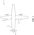
- an aircraft 1 is shown.
- the aircraft 1 is of conventional configuration, having a fuselage 2, wings 3, tail 4 and a pair of propulsion systems 5.
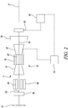
- One of the propulsion systems 5 is shown in detail in figure 2 .
- FIG. 2 shows the propulsion system 5 schematically.
- the propulsion system 5 includes an internal combustion engine in the form of a gas turbine engine 10.
- the gas turbine engine 10 comprises, in axial flow series, a compressor 14, combustion equipment 16 and high and low-pressure turbines 18, 20.
- the gas turbine engine 10 works in the conventional manner so that air flows through the compressor 14 where it is compressed, before delivering that air to the combustion equipment 16, where it is mixed with fuel and the mixture combusted. The resultant hot combustion products then expand through, and thereby drive the turbines 18, 20 before being exhausted through a nozzle.
- the high 18 and low-pressure turbines 20 drive respectively the compressor 14 and a propulsor 12 in the form of a propeller or fan, each by suitable interconnecting main engine shaft 22, 24, which rotate about an axis of rotation X.
- the low-pressure shaft 24 is coupled to the propulsor 12 via a clutch arrangement 50 and an optional reduction gearbox 36.
- the gearbox 36 could be of any suitable type, such as an epicyclic gearbox.
- gas turbine engines to which the present disclosure may be applied may have alternative configurations.
- such engines may have an alternative number of interconnecting shafts (e.g. three) and/or an alternative number of compressors and/or turbines.
- the engine may comprise a gearbox provided in the drive train from a turbine to a compressor and/or fan.
- the propulsion system 5 further comprises one or more electrical machines driving the propulsor 12.
- the system 5 comprises an electric motor 28.
- the motor 28 is of a conventional type, such as an induction or permanent magnet electric machine, and is configured to drive a propulsor such as the fan 12.
- the motor 28 comprises a permanent magnet AC motor, and is coupled to the fan 12 via a motor shaft 56, clutch arrangement 50, and reduction gearbox 36, which will be described in further detail later.
- the electric motor 28 is shown in further detail in figure 4 .
- the motor 28 is of conventional construction, comprising a stator 70 comprising a plurality of stator coils (not shown), which are energised in use to produce a rotating magnetic field.
- This rotating magnetic field crosses an air gap to link with a magnetic field produced by permanent magnets of a rotor 78. Consequently, the motor 28 acts as a motor when the stators 72 are energised.
- the rotor permanent magnets produce a rotating magnetic field, which links with the stator windings 72 to produce an electric current, and so may act as a generator under some circumstances.
- the electric motor 28 is positioned such that the stator 70 and rotor 78 surround a main engine shaft, which in this case comprises the low-pressure shaft 24.
- the motor 28 is of an "in-runner" type, in which the rotor 78 is provided radially inward of the stator 70.
- the rotor 78 is coupled to the low-pressure shaft 24 via the clutch arrangement 50, and is configured with an axis of rotation which is co-axial with the axis of rotation X of the low-pressure turbine 24.
- the electric motor 28 is coupled to an energy storage device 30 in the form of one or more of a chemical battery, fuel cell, and capacitor, which provides the electric motor 28 with electrical power during operation.
- an energy storage device 30 in the form of one or more of a chemical battery, fuel cell, and capacitor, which provides the electric motor 28 with electrical power during operation.
- multiple energy storages systems which may be of different types (chemical battery, fuel cell etc) may be provided for each propulsion system 5.
- a common energy storage device 30 may be provided for multiple propulsion systems.
- the propulsion system further comprises a generator 32, which is electrically coupled to one or both of the motor 28 and the energy storage device 30, such that additional electrical energy can be provided in operation.
- the generator 32 is typically driven by the low-pressure shaft 24 of the gas turbine engine 10.
- a controller 34 is provided, which is configured to control at least the motor 28 and energy storage device 30, to control the torque provided by the motor 28, and the charging / discharging of the energy storage device 30.
- the controller 34 may also be configured to control operation of the generator 32, to control electrical power produced by the generator 32.
- the gas turbine engine 10 and electric motor 28 are each coupled to the propulsor 12 via a clutch arrangement 50 comprising respective first and second overrunning clutches 52, 54 (also known as “freewheel” clutches).
- the clutch arrangement 50 comprises a first clutch in the form of a first overrunning clutch 52.
- the first clutch 52 comprises an inner race 58, which is coupled to the low-pressure shaft 24.
- An outer race 60 is provided, which is coupled to a fan shaft 62, which is in turn coupled to the fan 12 via the reduction gearbox 36.
- the outer race 60 of the first overrunning clutch 52 also forms an inner race of the second overrunning clutch 54.
- the second overrunning clutch 54 further comprises an outer race 64, which is coupled to the motor shaft 56 and is provided radially outward of the outer race 60 of the first clutch 52.
- the propulsor 12 is coupled to both the main engine shaft 24 and electric machine 28 via the first and second overrunning clutches 52, 54 respectively.
- Each of the shafts 24, 56, 62 is co-axial, and the arrangement is radially nested, with the main engine shaft 24 being coupled to a radially innermost race 58, the outer race 60 of the first clutch 54 being provided radially outward and coupled to the propulsor shaft 62, and the outer race 64 of the second clutch 54 being provided at the radially outermost position, and coupled to the motor shaft 56.
- the shafts 24, 56 could instead be reversed, with the shaft 56 being nested inside the shaft 24.
- the overrunning clutches 50, 52 are typically in the form of freewheel clutches, although other overrunning clutch types are known.
- the freewheel clutches 52, 54 comprises an input comprising the low-pressure shaft 24 of the gas turbine engine 10 and the motor shaft 56 respectively.
- An output shaft in the form of the propulsor shaft 62 is provided, which is coupled to the radially outer race of the first clutch 52, which forms the radially inner race of the second clutch 54.
- the first clutch 52 is arranged such that the races 58, 60, and so the shafts 24, 62 are locked together to transfer torque when torque is applied by the shaft 24 to the inner race 58 in a first direction, and when the speed of the input shaft 24 is equal to the speed of the output shaft 62.
- shafts 62, 24 rotate freely relative to one another, such that no torque is transmitted back to the input shaft 24, when the shaft 62 rotates at a higher speed in the first direction than the input shaft 24, or where the input shaft 24 rotates in a direction opposite to the first direction. Consequently, torque is transferred from the input shaft 24 to the shaft 62 only, and not the other way around.
- the second clutch 54 is arranged such that the shafts 56, 62 are locked together to transfer torque when torque is applied by the shaft 56 to the outer race 60 in the first direction, and when the speed of the input shaft 56 is equal to the speed of the output shaft 62.
- shafts 56, 62 rotate freely relative to one another, such that no torque is transmitted back to the input shaft 56, when the shaft 62 rotates at a higher speed in the first direction than the input shaft 24, or where the input shaft 24 rotates in a direction opposite to the first direction. Consequently, the fan 12 may be powered by either or both of the gas turbine engine 10 via the low-pressure shaft, and the motor 28.
- the freewheel clutches 52, 54 are arranged "backwards" relative to one another. Consequently, rotation of the shaft 24 at a higher speed than the shaft 56 will causes the shafts 24, 62 to lock and rotate together, and also cause the shafts 56, 62 to unlock, to rotate independently of one another. Conversely, rotation of the shaft 56 at a higher speed than the shaft 24 will causes the shafts 56, 62 to lock and rotate together, and also cause the shafts 24, 62 to unlock, to rotate independently of one another
- the shaft 62 will be driven by the shaft 24, 56 having the highest rotational speed relative to the other shaft 56, 24. Consequently, one shaft 56, 24 can be driven to provide for rotation of the output shaft 62, without causing rotation of the other shaft 24, 56.
- the gas turbine engine 10 is used to drive the propulsor 12 alone.
- the windings 72 of the motor 28 are not energised with electrical power from either the generator 32 or the batteries 30.
- the first freewheel clutch 52 engages in view of the torque input from the low-pressure shaft 24. Consequently, rotation of the low pressure shaft 24 drives the propulsor 12 via the reduction gearbox 36.
- the second clutch 54 disengages, in view of the rotation of the inner race relative to the shaft 56, and the non-rotation of the motor shaft 62. Consequently, the electric machine 28 is not driven.
- the electric motor 28 comprises a permanent magnet motor, since rotation of the rotor 78 would normally generate electrical current. This may not be desirable, as this will reduce the amount of power available to drive the propulsor 12, and will also generate additional heat. This mode of operation is also useful where the motor 28 has suffered a fault. Consequently, the motor 28 does not have to be of a "fault tolerant" type, which may reduce cost and weight.
- a second operational mode the motor 28 is used to drive the propulsor 12 alone.
- the gas turbine engine 10 is shut-down.
- the second freewheel clutch 54 engages in view of the torque input from the motor 28, and the load imposed by the propulsor 12. Consequently, rotation of the motor 28 drives the propulsor 12 via the reduction gearbox 36.
- the first clutch 52 disengages, in view of the rotation of the shaft 62, and the non-rotation of the low pressure shaft 24. Consequently, the gas turbine engine 10 is not driven.
- This mode of operation allows the gas turbine engine 10 to be shut-down in flight. Since gas turbine engines are only efficient when operated at high power, this may reduce overall fuel usage.
- the propulsor 12 can continue to be driven by the electric motor 28 in the event of a failure of the gas turbine engine 10, even where the gas turbine engine is not able to rotate due to the failure. Again, this increases safety, and improves operational flexibility.
- a third operational mode the gas turbine engine 10 and the motor are used to drive the propulsor 12 together.
- the windings 72 of the motor 28 are energised with electrical power from either the generator 32 or the batteries 30, and the gas turbine engine 10 is also operated to generate torque.
- both clutches 52, 54 engage in view of the torque input from the low pressure shaft 24 and the motor 28, which causes shafts 24, 56 to rotate at the same speed. Consequently, rotation of the low pressure shaft 24 and the motor 28 drive the propulsor 12 via the reduction gearbox 36.
- load is shared between the gas turbine engine 10 and motor 28. This mode is particularly advantageous for operation at high power levels, such as take-off, where increased power is required.
- the present arrangement describes a lightweight, reliable aircraft propulsion system, which is flexible, efficient, and tolerant of failures.
- the system allows for provision of an electric machine that is co-axial with the main gas turbine engine shaft, while providing for automatic connection and disconnection of the gas turbine engine and electric machine under various circumstances.
- Such a system is compact. No additional actuation is required, which makes the system lightweight and reliable.
- the gas turbine engine could take a different form.
- the gas turbine engine could comprise additional compressors, which may be driven by one or more of the shafts, or by additional, independently rotatable shafts.
- Different forms of overrunning clutches could be used.
- the reduction gearbox could be omitted, as could the generator, with the electric machine being supplied with electric power from an energy storage device alone.
- the electric machine could take a different physical form, being an "out runner", in which the electric machine rotor is provided radially outward of the stator, or the electric machine could comprise an axial flux machine.
Landscapes
- Engineering & Computer Science (AREA)
- Mechanical Engineering (AREA)
- Aviation & Aerospace Engineering (AREA)
- Chemical & Material Sciences (AREA)
- Combustion & Propulsion (AREA)
- General Engineering & Computer Science (AREA)
- Power Engineering (AREA)
- Connection Of Motors, Electrical Generators, Mechanical Devices, And The Like (AREA)
Applications Claiming Priority (1)
| Application Number | Priority Date | Filing Date | Title |
|---|---|---|---|
| GBGB1918282.3A GB201918282D0 (en) | 2019-12-12 | 2019-12-12 | Aircraft hybrid propulsion system |
Publications (2)
| Publication Number | Publication Date |
|---|---|
| EP3835557A1 true EP3835557A1 (de) | 2021-06-16 |
| EP3835557B1 EP3835557B1 (de) | 2023-06-21 |
Family
ID=69173077
Family Applications (1)
| Application Number | Title | Priority Date | Filing Date |
|---|---|---|---|
| EP20207060.3A Active EP3835557B1 (de) | 2019-12-12 | 2020-11-12 | Hybridantriebssystem für flugzeuge |
Country Status (4)
| Country | Link |
|---|---|
| US (1) | US11891184B2 (de) |
| EP (1) | EP3835557B1 (de) |
| CN (1) | CN112977846A (de) |
| GB (1) | GB201918282D0 (de) |
Cited By (1)
| Publication number | Priority date | Publication date | Assignee | Title |
|---|---|---|---|---|
| FR3148579A1 (fr) * | 2023-05-09 | 2024-11-15 | Safran | Ensemble propulsif pour aéronef comprenant une turbomachine à gaz, une pile à combustible, deux machines électriques et un système de transmission |
Families Citing this family (6)
| Publication number | Priority date | Publication date | Assignee | Title |
|---|---|---|---|---|
| US11629651B2 (en) * | 2020-11-17 | 2023-04-18 | General Electric Company | Gas turbine engine having a turbomachine and an electric motor coupled to a propeller |
| US11787550B1 (en) | 2022-05-04 | 2023-10-17 | Beta Air, Llc | Propulsor assembly powered by a dual motor system |
| US12145738B2 (en) * | 2022-08-22 | 2024-11-19 | Pratt & Whitney Canada Corp. | Multi-drive unit propulsion system for an aircraft |
| FR3141208A1 (fr) * | 2022-10-20 | 2024-04-26 | Safran Aircraft Engines | Procédé et module de détection de l’état d’un dispositif d’accouplement, turbomachine et aéronef associés |
| US12583608B2 (en) | 2023-05-12 | 2026-03-24 | Pratt & Whitney Canada Corp. | Electric motor propulsion system for an aircraft |
| CN119532058B (zh) * | 2023-08-28 | 2025-09-16 | 西北工业大学 | 一种与燃料电池集成的双驱动式旋转爆震发动机 |
Citations (3)
| Publication number | Priority date | Publication date | Assignee | Title |
|---|---|---|---|---|
| US20120076674A1 (en) * | 2010-09-24 | 2012-03-29 | Aisin Aw Co., Ltd. | Liquid pressure generating apparatus and driving apparatus |
| EP3530928A1 (de) * | 2018-02-26 | 2019-08-28 | The Boeing Company | Hybridturbinenstrahltriebwerk und verfahren zum betrieb davon |
| EP3556659A1 (de) * | 2018-04-19 | 2019-10-23 | The Boeing Company | Hybridantriebsmotoren für flugzeuge |
Family Cites Families (5)
| Publication number | Priority date | Publication date | Assignee | Title |
|---|---|---|---|---|
| US4139780A (en) * | 1977-11-17 | 1979-02-13 | Sundstrand Corporation | Multi-channel generator drive system |
| GB0809336D0 (en) * | 2008-05-23 | 2008-07-02 | Rolls Royce Plc | A gas turbine engine arrangement |
| US9527375B2 (en) * | 2014-08-20 | 2016-12-27 | Gm Global Technoogy Operations Llc | Powertrain with transmission-based motor/generator for engine starting and regenerative braking modes |
| US9933024B2 (en) * | 2014-09-05 | 2018-04-03 | Avl Powertrain Engineering, Inc. | Variable two-way over-running clutch |
| US10968825B2 (en) * | 2018-04-19 | 2021-04-06 | The Boeing Company | Flow multiplier systems for aircraft |
-
2019
- 2019-12-12 GB GBGB1918282.3A patent/GB201918282D0/en not_active Ceased
-
2020
- 2020-11-12 EP EP20207060.3A patent/EP3835557B1/de active Active
- 2020-11-16 US US17/098,758 patent/US11891184B2/en active Active
- 2020-12-11 CN CN202011449863.9A patent/CN112977846A/zh active Pending
Patent Citations (3)
| Publication number | Priority date | Publication date | Assignee | Title |
|---|---|---|---|---|
| US20120076674A1 (en) * | 2010-09-24 | 2012-03-29 | Aisin Aw Co., Ltd. | Liquid pressure generating apparatus and driving apparatus |
| EP3530928A1 (de) * | 2018-02-26 | 2019-08-28 | The Boeing Company | Hybridturbinenstrahltriebwerk und verfahren zum betrieb davon |
| EP3556659A1 (de) * | 2018-04-19 | 2019-10-23 | The Boeing Company | Hybridantriebsmotoren für flugzeuge |
Cited By (1)
| Publication number | Priority date | Publication date | Assignee | Title |
|---|---|---|---|---|
| FR3148579A1 (fr) * | 2023-05-09 | 2024-11-15 | Safran | Ensemble propulsif pour aéronef comprenant une turbomachine à gaz, une pile à combustible, deux machines électriques et un système de transmission |
Also Published As
| Publication number | Publication date |
|---|---|
| EP3835557B1 (de) | 2023-06-21 |
| US11891184B2 (en) | 2024-02-06 |
| GB201918282D0 (en) | 2020-01-29 |
| CN112977846A (zh) | 2021-06-18 |
| US20210179282A1 (en) | 2021-06-17 |
Similar Documents
| Publication | Publication Date | Title |
|---|---|---|
| US11891184B2 (en) | Aircraft hybrid propulsion system | |
| US11745888B2 (en) | Aircraft hybrid propulsion system | |
| CN112805218B (zh) | 包括混合动力系的机器和相应的控制方法 | |
| US11485503B2 (en) | Hybrid aircraft propulsion power plants | |
| RU2767577C2 (ru) | Гибридная пропульсивная конструкция для летательного аппарата, содержащего двигатель с реверсивной электрической машиной, установленной на двух валах | |
| AU2012300727B2 (en) | Aircraft comprising a distributed electric power unit with free wheels | |
| JP7026989B2 (ja) | ハイブリッド電気駆動システム | |
| US20230366344A1 (en) | Mechanical disconnects for parallel power lanes in hybrid electric propulsion systems | |
| EP3941830A2 (de) | Architekturen für hybrid-elektro-antrieb | |
| ES2929412T3 (es) | Sistemas eléctricos | |
| CN103814507A (zh) | 用于旋转翼航空器或固定翼航空器的电磁功率传输装置 | |
| US20240239509A1 (en) | Improved transmission device for hybrid aircraft | |
| JP7522768B2 (ja) | ハイブリッド動力伝達機構を備えるマシンと対応する制御方法 | |
| GB2594072A (en) | Hybrid aircraft propulsion system | |
| CN119032046A (zh) | 用于多引擎混合动力飞行器的改进型推进组件 | |
| US12467378B2 (en) | Free turbine turbogenerator comprising a reversible electrical machine coupled to the free turbine | |
| CN114174173B (zh) | 包括辅助机械驱动系统的飞行器混合动力推进链 | |
| CN121399357A (zh) | 用于多发动机混合动力飞行器的改进的推进组件 | |
| CN119173685A (zh) | 用于混合动力航空器的改进的涡轮机 | |
| US20250242928A1 (en) | Hybrid aircraft power plant and gearbox therefor | |
| CN120344756A (zh) | 用于飞行器的改进的混合动力涡轮螺旋桨发动机 | |
| CA3262672A1 (en) | Hybrid aircraft power plant and gearbox therefor |
Legal Events
| Date | Code | Title | Description |
|---|---|---|---|
| PUAI | Public reference made under article 153(3) epc to a published international application that has entered the european phase |
Free format text: ORIGINAL CODE: 0009012 |
|
| STAA | Information on the status of an ep patent application or granted ep patent |
Free format text: STATUS: THE APPLICATION HAS BEEN PUBLISHED |
|
| AK | Designated contracting states |
Kind code of ref document: A1 Designated state(s): AL AT BE BG CH CY CZ DE DK EE ES FI FR GB GR HR HU IE IS IT LI LT LU LV MC MK MT NL NO PL PT RO RS SE SI SK SM TR |
|
| STAA | Information on the status of an ep patent application or granted ep patent |
Free format text: STATUS: REQUEST FOR EXAMINATION WAS MADE |
|
| 17P | Request for examination filed |
Effective date: 20210621 |
|
| RBV | Designated contracting states (corrected) |
Designated state(s): AL AT BE BG CH CY CZ DE DK EE ES FI FR GB GR HR HU IE IS IT LI LT LU LV MC MK MT NL NO PL PT RO RS SE SI SK SM TR |
|
| STAA | Information on the status of an ep patent application or granted ep patent |
Free format text: STATUS: EXAMINATION IS IN PROGRESS |
|
| 17Q | First examination report despatched |
Effective date: 20211116 |
|
| GRAP | Despatch of communication of intention to grant a patent |
Free format text: ORIGINAL CODE: EPIDOSNIGR1 |
|
| STAA | Information on the status of an ep patent application or granted ep patent |
Free format text: STATUS: GRANT OF PATENT IS INTENDED |
|
| GRAS | Grant fee paid |
Free format text: ORIGINAL CODE: EPIDOSNIGR3 |
|
| INTG | Intention to grant announced |
Effective date: 20230420 |
|
| GRAA | (expected) grant |
Free format text: ORIGINAL CODE: 0009210 |
|
| STAA | Information on the status of an ep patent application or granted ep patent |
Free format text: STATUS: THE PATENT HAS BEEN GRANTED |
|
| AK | Designated contracting states |
Kind code of ref document: B1 Designated state(s): AL AT BE BG CH CY CZ DE DK EE ES FI FR GB GR HR HU IE IS IT LI LT LU LV MC MK MT NL NO PL PT RO RS SE SI SK SM TR |
|
| REG | Reference to a national code |
Ref country code: CH Ref legal event code: EP |
|
| REG | Reference to a national code |
Ref country code: DE Ref legal event code: R096 Ref document number: 602020012729 Country of ref document: DE |
|
| P01 | Opt-out of the competence of the unified patent court (upc) registered |
Effective date: 20230528 |
|
| REG | Reference to a national code |
Ref country code: AT Ref legal event code: REF Ref document number: 1581048 Country of ref document: AT Kind code of ref document: T Effective date: 20230715 |
|
| REG | Reference to a national code |
Ref country code: IE Ref legal event code: FG4D |
|
| REG | Reference to a national code |
Ref country code: LT Ref legal event code: MG9D |
|
| REG | Reference to a national code |
Ref country code: NL Ref legal event code: MP Effective date: 20230621 |
|
| PG25 | Lapsed in a contracting state [announced via postgrant information from national office to epo] |
Ref country code: SE Free format text: LAPSE BECAUSE OF FAILURE TO SUBMIT A TRANSLATION OF THE DESCRIPTION OR TO PAY THE FEE WITHIN THE PRESCRIBED TIME-LIMIT Effective date: 20230621 Ref country code: NO Free format text: LAPSE BECAUSE OF FAILURE TO SUBMIT A TRANSLATION OF THE DESCRIPTION OR TO PAY THE FEE WITHIN THE PRESCRIBED TIME-LIMIT Effective date: 20230921 |
|
| REG | Reference to a national code |
Ref country code: AT Ref legal event code: MK05 Ref document number: 1581048 Country of ref document: AT Kind code of ref document: T Effective date: 20230621 |
|
| PG25 | Lapsed in a contracting state [announced via postgrant information from national office to epo] |
Ref country code: RS Free format text: LAPSE BECAUSE OF FAILURE TO SUBMIT A TRANSLATION OF THE DESCRIPTION OR TO PAY THE FEE WITHIN THE PRESCRIBED TIME-LIMIT Effective date: 20230621 Ref country code: NL Free format text: LAPSE BECAUSE OF FAILURE TO SUBMIT A TRANSLATION OF THE DESCRIPTION OR TO PAY THE FEE WITHIN THE PRESCRIBED TIME-LIMIT Effective date: 20230621 Ref country code: LV Free format text: LAPSE BECAUSE OF FAILURE TO SUBMIT A TRANSLATION OF THE DESCRIPTION OR TO PAY THE FEE WITHIN THE PRESCRIBED TIME-LIMIT Effective date: 20230621 Ref country code: LT Free format text: LAPSE BECAUSE OF FAILURE TO SUBMIT A TRANSLATION OF THE DESCRIPTION OR TO PAY THE FEE WITHIN THE PRESCRIBED TIME-LIMIT Effective date: 20230621 Ref country code: HR Free format text: LAPSE BECAUSE OF FAILURE TO SUBMIT A TRANSLATION OF THE DESCRIPTION OR TO PAY THE FEE WITHIN THE PRESCRIBED TIME-LIMIT Effective date: 20230621 Ref country code: GR Free format text: LAPSE BECAUSE OF FAILURE TO SUBMIT A TRANSLATION OF THE DESCRIPTION OR TO PAY THE FEE WITHIN THE PRESCRIBED TIME-LIMIT Effective date: 20230922 |
|
| PG25 | Lapsed in a contracting state [announced via postgrant information from national office to epo] |
Ref country code: FI Free format text: LAPSE BECAUSE OF FAILURE TO SUBMIT A TRANSLATION OF THE DESCRIPTION OR TO PAY THE FEE WITHIN THE PRESCRIBED TIME-LIMIT Effective date: 20230621 |
|
| PG25 | Lapsed in a contracting state [announced via postgrant information from national office to epo] |
Ref country code: SK Free format text: LAPSE BECAUSE OF FAILURE TO SUBMIT A TRANSLATION OF THE DESCRIPTION OR TO PAY THE FEE WITHIN THE PRESCRIBED TIME-LIMIT Effective date: 20230621 |
|
| PG25 | Lapsed in a contracting state [announced via postgrant information from national office to epo] |
Ref country code: ES Free format text: LAPSE BECAUSE OF FAILURE TO SUBMIT A TRANSLATION OF THE DESCRIPTION OR TO PAY THE FEE WITHIN THE PRESCRIBED TIME-LIMIT Effective date: 20230621 |
|
| PG25 | Lapsed in a contracting state [announced via postgrant information from national office to epo] |
Ref country code: IS Free format text: LAPSE BECAUSE OF FAILURE TO SUBMIT A TRANSLATION OF THE DESCRIPTION OR TO PAY THE FEE WITHIN THE PRESCRIBED TIME-LIMIT Effective date: 20231021 |
|
| PG25 | Lapsed in a contracting state [announced via postgrant information from national office to epo] |
Ref country code: SM Free format text: LAPSE BECAUSE OF FAILURE TO SUBMIT A TRANSLATION OF THE DESCRIPTION OR TO PAY THE FEE WITHIN THE PRESCRIBED TIME-LIMIT Effective date: 20230621 Ref country code: SK Free format text: LAPSE BECAUSE OF FAILURE TO SUBMIT A TRANSLATION OF THE DESCRIPTION OR TO PAY THE FEE WITHIN THE PRESCRIBED TIME-LIMIT Effective date: 20230621 Ref country code: RO Free format text: LAPSE BECAUSE OF FAILURE TO SUBMIT A TRANSLATION OF THE DESCRIPTION OR TO PAY THE FEE WITHIN THE PRESCRIBED TIME-LIMIT Effective date: 20230621 Ref country code: PT Free format text: LAPSE BECAUSE OF FAILURE TO SUBMIT A TRANSLATION OF THE DESCRIPTION OR TO PAY THE FEE WITHIN THE PRESCRIBED TIME-LIMIT Effective date: 20231023 Ref country code: IS Free format text: LAPSE BECAUSE OF FAILURE TO SUBMIT A TRANSLATION OF THE DESCRIPTION OR TO PAY THE FEE WITHIN THE PRESCRIBED TIME-LIMIT Effective date: 20231021 Ref country code: ES Free format text: LAPSE BECAUSE OF FAILURE TO SUBMIT A TRANSLATION OF THE DESCRIPTION OR TO PAY THE FEE WITHIN THE PRESCRIBED TIME-LIMIT Effective date: 20230621 Ref country code: EE Free format text: LAPSE BECAUSE OF FAILURE TO SUBMIT A TRANSLATION OF THE DESCRIPTION OR TO PAY THE FEE WITHIN THE PRESCRIBED TIME-LIMIT Effective date: 20230621 Ref country code: CZ Free format text: LAPSE BECAUSE OF FAILURE TO SUBMIT A TRANSLATION OF THE DESCRIPTION OR TO PAY THE FEE WITHIN THE PRESCRIBED TIME-LIMIT Effective date: 20230621 Ref country code: AT Free format text: LAPSE BECAUSE OF FAILURE TO SUBMIT A TRANSLATION OF THE DESCRIPTION OR TO PAY THE FEE WITHIN THE PRESCRIBED TIME-LIMIT Effective date: 20230621 |
|
| PG25 | Lapsed in a contracting state [announced via postgrant information from national office to epo] |
Ref country code: PL Free format text: LAPSE BECAUSE OF FAILURE TO SUBMIT A TRANSLATION OF THE DESCRIPTION OR TO PAY THE FEE WITHIN THE PRESCRIBED TIME-LIMIT Effective date: 20230621 |
|
| REG | Reference to a national code |
Ref country code: DE Ref legal event code: R097 Ref document number: 602020012729 Country of ref document: DE |
|
| PLBE | No opposition filed within time limit |
Free format text: ORIGINAL CODE: 0009261 |
|
| STAA | Information on the status of an ep patent application or granted ep patent |
Free format text: STATUS: NO OPPOSITION FILED WITHIN TIME LIMIT |
|
| PG25 | Lapsed in a contracting state [announced via postgrant information from national office to epo] |
Ref country code: DK Free format text: LAPSE BECAUSE OF FAILURE TO SUBMIT A TRANSLATION OF THE DESCRIPTION OR TO PAY THE FEE WITHIN THE PRESCRIBED TIME-LIMIT Effective date: 20230621 |
|
| PG25 | Lapsed in a contracting state [announced via postgrant information from national office to epo] |
Ref country code: SI Free format text: LAPSE BECAUSE OF FAILURE TO SUBMIT A TRANSLATION OF THE DESCRIPTION OR TO PAY THE FEE WITHIN THE PRESCRIBED TIME-LIMIT Effective date: 20230621 |
|
| 26N | No opposition filed |
Effective date: 20240322 |
|
| PG25 | Lapsed in a contracting state [announced via postgrant information from national office to epo] |
Ref country code: SI Free format text: LAPSE BECAUSE OF FAILURE TO SUBMIT A TRANSLATION OF THE DESCRIPTION OR TO PAY THE FEE WITHIN THE PRESCRIBED TIME-LIMIT Effective date: 20230621 Ref country code: IT Free format text: LAPSE BECAUSE OF FAILURE TO SUBMIT A TRANSLATION OF THE DESCRIPTION OR TO PAY THE FEE WITHIN THE PRESCRIBED TIME-LIMIT Effective date: 20230621 |
|
| REG | Reference to a national code |
Ref country code: CH Ref legal event code: PL |
|
| PG25 | Lapsed in a contracting state [announced via postgrant information from national office to epo] |
Ref country code: MC Free format text: LAPSE BECAUSE OF FAILURE TO SUBMIT A TRANSLATION OF THE DESCRIPTION OR TO PAY THE FEE WITHIN THE PRESCRIBED TIME-LIMIT Effective date: 20230621 |
|
| PG25 | Lapsed in a contracting state [announced via postgrant information from national office to epo] |
Ref country code: LU Free format text: LAPSE BECAUSE OF NON-PAYMENT OF DUE FEES Effective date: 20231112 |
|
| PG25 | Lapsed in a contracting state [announced via postgrant information from national office to epo] |
Ref country code: CH Free format text: LAPSE BECAUSE OF NON-PAYMENT OF DUE FEES Effective date: 20231130 |
|
| PG25 | Lapsed in a contracting state [announced via postgrant information from national office to epo] |
Ref country code: MC Free format text: LAPSE BECAUSE OF FAILURE TO SUBMIT A TRANSLATION OF THE DESCRIPTION OR TO PAY THE FEE WITHIN THE PRESCRIBED TIME-LIMIT Effective date: 20230621 Ref country code: LU Free format text: LAPSE BECAUSE OF NON-PAYMENT OF DUE FEES Effective date: 20231112 Ref country code: CH Free format text: LAPSE BECAUSE OF NON-PAYMENT OF DUE FEES Effective date: 20231130 |
|
| REG | Reference to a national code |
Ref country code: BE Ref legal event code: MM Effective date: 20231130 |
|
| REG | Reference to a national code |
Ref country code: IE Ref legal event code: MM4A |
|
| PG25 | Lapsed in a contracting state [announced via postgrant information from national office to epo] |
Ref country code: IE Free format text: LAPSE BECAUSE OF NON-PAYMENT OF DUE FEES Effective date: 20231112 |
|
| PG25 | Lapsed in a contracting state [announced via postgrant information from national office to epo] |
Ref country code: BE Free format text: LAPSE BECAUSE OF NON-PAYMENT OF DUE FEES Effective date: 20231130 |
|
| PG25 | Lapsed in a contracting state [announced via postgrant information from national office to epo] |
Ref country code: IE Free format text: LAPSE BECAUSE OF NON-PAYMENT OF DUE FEES Effective date: 20231112 Ref country code: BE Free format text: LAPSE BECAUSE OF NON-PAYMENT OF DUE FEES Effective date: 20231130 |
|
| PG25 | Lapsed in a contracting state [announced via postgrant information from national office to epo] |
Ref country code: BG Free format text: LAPSE BECAUSE OF FAILURE TO SUBMIT A TRANSLATION OF THE DESCRIPTION OR TO PAY THE FEE WITHIN THE PRESCRIBED TIME-LIMIT Effective date: 20230621 |
|
| PG25 | Lapsed in a contracting state [announced via postgrant information from national office to epo] |
Ref country code: BG Free format text: LAPSE BECAUSE OF FAILURE TO SUBMIT A TRANSLATION OF THE DESCRIPTION OR TO PAY THE FEE WITHIN THE PRESCRIBED TIME-LIMIT Effective date: 20230621 |
|
| PG25 | Lapsed in a contracting state [announced via postgrant information from national office to epo] |
Ref country code: CY Free format text: LAPSE BECAUSE OF FAILURE TO SUBMIT A TRANSLATION OF THE DESCRIPTION OR TO PAY THE FEE WITHIN THE PRESCRIBED TIME-LIMIT; INVALID AB INITIO Effective date: 20201112 |
|
| PG25 | Lapsed in a contracting state [announced via postgrant information from national office to epo] |
Ref country code: HU Free format text: LAPSE BECAUSE OF FAILURE TO SUBMIT A TRANSLATION OF THE DESCRIPTION OR TO PAY THE FEE WITHIN THE PRESCRIBED TIME-LIMIT; INVALID AB INITIO Effective date: 20201112 |
|
| PG25 | Lapsed in a contracting state [announced via postgrant information from national office to epo] |
Ref country code: TR Free format text: LAPSE BECAUSE OF FAILURE TO SUBMIT A TRANSLATION OF THE DESCRIPTION OR TO PAY THE FEE WITHIN THE PRESCRIBED TIME-LIMIT Effective date: 20230621 |
|
| PGFP | Annual fee paid to national office [announced via postgrant information from national office to epo] |
Ref country code: DE Payment date: 20251126 Year of fee payment: 6 |
|
| PGFP | Annual fee paid to national office [announced via postgrant information from national office to epo] |
Ref country code: GB Payment date: 20251125 Year of fee payment: 6 |
|
| PGFP | Annual fee paid to national office [announced via postgrant information from national office to epo] |
Ref country code: FR Payment date: 20251124 Year of fee payment: 6 |