EP3835558A1 - Umweltkontrollsystem - Google Patents
Umweltkontrollsystem Download PDFInfo
- Publication number
- EP3835558A1 EP3835558A1 EP20208164.2A EP20208164A EP3835558A1 EP 3835558 A1 EP3835558 A1 EP 3835558A1 EP 20208164 A EP20208164 A EP 20208164A EP 3835558 A1 EP3835558 A1 EP 3835558A1
- Authority
- EP
- European Patent Office
- Prior art keywords
- blower
- pack
- signal
- controller
- airflow
- Prior art date
- Legal status (The legal status is an assumption and is not a legal conclusion. Google has not performed a legal analysis and makes no representation as to the accuracy of the status listed.)
- Granted
Links
Images


Classifications
-
- F—MECHANICAL ENGINEERING; LIGHTING; HEATING; WEAPONS; BLASTING
- F02—COMBUSTION ENGINES; HOT-GAS OR COMBUSTION-PRODUCT ENGINE PLANTS
- F02C—GAS-TURBINE PLANTS; AIR INTAKES FOR JET-PROPULSION PLANTS; CONTROLLING FUEL SUPPLY IN AIR-BREATHING JET-PROPULSION PLANTS
- F02C6/00—Plural gas-turbine plants; Combinations of gas-turbine plants with other apparatus; Adaptations of gas-turbine plants for special use
- F02C6/04—Gas-turbine plants providing heated or pressurised working fluid for other apparatus, e.g. without mechanical power output
- F02C6/06—Gas-turbine plants providing heated or pressurised working fluid for other apparatus, e.g. without mechanical power output providing compressed gas
- F02C6/08—Gas-turbine plants providing heated or pressurised working fluid for other apparatus, e.g. without mechanical power output providing compressed gas the gas being bled from the gas-turbine compressor
-
- B—PERFORMING OPERATIONS; TRANSPORTING
- B64—AIRCRAFT; AVIATION; COSMONAUTICS
- B64D—EQUIPMENT FOR FITTING IN OR TO AIRCRAFT; FLIGHT SUITS; PARACHUTES; ARRANGEMENT OR MOUNTING OF POWER PLANTS OR PROPULSION TRANSMISSIONS IN AIRCRAFT
- B64D13/00—Arrangements or adaptations of air-treatment apparatus for aircraft crew or passengers, or freight space
- B64D13/02—Arrangements or adaptations of air-treatment apparatus for aircraft crew or passengers, or freight space the air being pressurised
-
- B—PERFORMING OPERATIONS; TRANSPORTING
- B64—AIRCRAFT; AVIATION; COSMONAUTICS
- B64D—EQUIPMENT FOR FITTING IN OR TO AIRCRAFT; FLIGHT SUITS; PARACHUTES; ARRANGEMENT OR MOUNTING OF POWER PLANTS OR PROPULSION TRANSMISSIONS IN AIRCRAFT
- B64D13/00—Arrangements or adaptations of air-treatment apparatus for aircraft crew or passengers, or freight space
- B64D13/06—Arrangements or adaptations of air-treatment apparatus for aircraft crew or passengers, or freight space the air being conditioned
-
- B—PERFORMING OPERATIONS; TRANSPORTING
- B64—AIRCRAFT; AVIATION; COSMONAUTICS
- B64D—EQUIPMENT FOR FITTING IN OR TO AIRCRAFT; FLIGHT SUITS; PARACHUTES; ARRANGEMENT OR MOUNTING OF POWER PLANTS OR PROPULSION TRANSMISSIONS IN AIRCRAFT
- B64D15/00—De-icing or preventing icing on exterior surfaces of aircraft
- B64D15/02—De-icing or preventing icing on exterior surfaces of aircraft by ducted hot gas or liquid
- B64D15/04—Hot gas application
-
- B—PERFORMING OPERATIONS; TRANSPORTING
- B64—AIRCRAFT; AVIATION; COSMONAUTICS
- B64D—EQUIPMENT FOR FITTING IN OR TO AIRCRAFT; FLIGHT SUITS; PARACHUTES; ARRANGEMENT OR MOUNTING OF POWER PLANTS OR PROPULSION TRANSMISSIONS IN AIRCRAFT
- B64D15/00—De-icing or preventing icing on exterior surfaces of aircraft
- B64D15/20—Means for detecting icing or initiating de-icing
-
- B—PERFORMING OPERATIONS; TRANSPORTING
- B64—AIRCRAFT; AVIATION; COSMONAUTICS
- B64D—EQUIPMENT FOR FITTING IN OR TO AIRCRAFT; FLIGHT SUITS; PARACHUTES; ARRANGEMENT OR MOUNTING OF POWER PLANTS OR PROPULSION TRANSMISSIONS IN AIRCRAFT
- B64D41/00—Power installations for auxiliary purposes
-
- F—MECHANICAL ENGINEERING; LIGHTING; HEATING; WEAPONS; BLASTING
- F04—POSITIVE - DISPLACEMENT MACHINES FOR LIQUIDS; PUMPS FOR LIQUIDS OR ELASTIC FLUIDS
- F04D—NON-POSITIVE-DISPLACEMENT PUMPS
- F04D25/00—Pumping installations or systems
- F04D25/02—Units comprising pumps and their driving means
- F04D25/06—Units comprising pumps and their driving means the pump being electrically driven
-
- F—MECHANICAL ENGINEERING; LIGHTING; HEATING; WEAPONS; BLASTING
- F04—POSITIVE - DISPLACEMENT MACHINES FOR LIQUIDS; PUMPS FOR LIQUIDS OR ELASTIC FLUIDS
- F04D—NON-POSITIVE-DISPLACEMENT PUMPS
- F04D27/00—Control, e.g. regulation, of pumps, pumping installations or pumping systems specially adapted for elastic fluids
- F04D27/002—Control, e.g. regulation, of pumps, pumping installations or pumping systems specially adapted for elastic fluids by varying geometry within the pumps, e.g. by adjusting vanes
-
- F—MECHANICAL ENGINEERING; LIGHTING; HEATING; WEAPONS; BLASTING
- F04—POSITIVE - DISPLACEMENT MACHINES FOR LIQUIDS; PUMPS FOR LIQUIDS OR ELASTIC FLUIDS
- F04D—NON-POSITIVE-DISPLACEMENT PUMPS
- F04D27/00—Control, e.g. regulation, of pumps, pumping installations or pumping systems specially adapted for elastic fluids
- F04D27/004—Control, e.g. regulation, of pumps, pumping installations or pumping systems specially adapted for elastic fluids by varying driving speed
-
- B—PERFORMING OPERATIONS; TRANSPORTING
- B64—AIRCRAFT; AVIATION; COSMONAUTICS
- B64D—EQUIPMENT FOR FITTING IN OR TO AIRCRAFT; FLIGHT SUITS; PARACHUTES; ARRANGEMENT OR MOUNTING OF POWER PLANTS OR PROPULSION TRANSMISSIONS IN AIRCRAFT
- B64D13/00—Arrangements or adaptations of air-treatment apparatus for aircraft crew or passengers, or freight space
- B64D13/06—Arrangements or adaptations of air-treatment apparatus for aircraft crew or passengers, or freight space the air being conditioned
- B64D2013/0603—Environmental Control Systems
- B64D2013/0607—Environmental Control Systems providing hot air or liquid for deicing aircraft parts, e.g. aerodynamic surfaces or windows
-
- B—PERFORMING OPERATIONS; TRANSPORTING
- B64—AIRCRAFT; AVIATION; COSMONAUTICS
- B64D—EQUIPMENT FOR FITTING IN OR TO AIRCRAFT; FLIGHT SUITS; PARACHUTES; ARRANGEMENT OR MOUNTING OF POWER PLANTS OR PROPULSION TRANSMISSIONS IN AIRCRAFT
- B64D13/00—Arrangements or adaptations of air-treatment apparatus for aircraft crew or passengers, or freight space
- B64D13/06—Arrangements or adaptations of air-treatment apparatus for aircraft crew or passengers, or freight space the air being conditioned
- B64D2013/0603—Environmental Control Systems
- B64D2013/0618—Environmental Control Systems with arrangements for reducing or managing bleed air, using another air source, e.g. ram air
-
- B—PERFORMING OPERATIONS; TRANSPORTING
- B64—AIRCRAFT; AVIATION; COSMONAUTICS
- B64D—EQUIPMENT FOR FITTING IN OR TO AIRCRAFT; FLIGHT SUITS; PARACHUTES; ARRANGEMENT OR MOUNTING OF POWER PLANTS OR PROPULSION TRANSMISSIONS IN AIRCRAFT
- B64D13/00—Arrangements or adaptations of air-treatment apparatus for aircraft crew or passengers, or freight space
- B64D13/06—Arrangements or adaptations of air-treatment apparatus for aircraft crew or passengers, or freight space the air being conditioned
- B64D2013/0603—Environmental Control Systems
- B64D2013/0644—Environmental Control Systems including electric motors or generators
-
- F—MECHANICAL ENGINEERING; LIGHTING; HEATING; WEAPONS; BLASTING
- F05—INDEXING SCHEMES RELATING TO ENGINES OR PUMPS IN VARIOUS SUBCLASSES OF CLASSES F01-F04
- F05D—INDEXING SCHEME FOR ASPECTS RELATING TO NON-POSITIVE-DISPLACEMENT MACHINES OR ENGINES, GAS-TURBINES OR JET-PROPULSION PLANTS
- F05D2270/00—Control
- F05D2270/30—Control parameters, e.g. input parameters
- F05D2270/306—Mass flow
-
- Y—GENERAL TAGGING OF NEW TECHNOLOGICAL DEVELOPMENTS; GENERAL TAGGING OF CROSS-SECTIONAL TECHNOLOGIES SPANNING OVER SEVERAL SECTIONS OF THE IPC; TECHNICAL SUBJECTS COVERED BY FORMER USPC CROSS-REFERENCE ART COLLECTIONS [XRACs] AND DIGESTS
- Y02—TECHNOLOGIES OR APPLICATIONS FOR MITIGATION OR ADAPTATION AGAINST CLIMATE CHANGE
- Y02T—CLIMATE CHANGE MITIGATION TECHNOLOGIES RELATED TO TRANSPORTATION
- Y02T50/00—Aeronautics or air transport
- Y02T50/50—On board measures aiming to increase energy efficiency
Definitions
- the present disclosure relates to an environmental control system for an aircraft and a controller for the environmental control system.
- ECS environmental control system
- the source of pressurised air for the ECS is represented by bleeds from the engine core compressors of the gas turbine engines of the aircraft.
- High pressure and high temperature bleed airflow is extracted from a low pressure port of each engine when the engine is operated at high power settings, such as during cruise.
- a high pressure port is also provided to supply air during low power settings operations, when the pressure at the low pressure port would not meet the ECS demand.
- a pressure regulating valve is provided to maintain the bleed pressure under acceptable limits.
- a portion of this bleed is sometimes used for engine or wing anti-icing purposes, or conveyed to other aircraft systems requiring pneumatic actuation.
- the remaining flow enters an air conditioning pack, where the air is cooled down to meet the cabin conditioning demand.
- air conditioning packs may be provided that may, for example, each be served by a particular turbine engine of the aircraft.
- the conditioned airflow is delivered to a mixing manifold where it is mixed with a portion of the cabin air prior to being discharged into the aircraft cabin.
- the airflow through the air conditioning pack is commonly controlled by a flow control valve assembly (e.g. a butterfly valve).
- This flow control valve may be controlled so as to provide a target (i.e. desired) flow rate through the air conditioning pack (and into the cabin).
- the bleed flow management of the ECS represents an inefficiency that ultimately increases the engine power offtake required to meet ECS demand (so as to in increase aircraft fuel consumption).
- a blower controller for controlling a blower that supplies a pressurised airflow to an air conditioning pack of an aircraft, the blower controller comprising:
- the disclosed controller may facilitate the provision of an aircraft environmental control system that does not require a number of pressure regulating and flow control valves present in the known systems discussed above. Such pressure regulating and flow control valves are associated with pressure losses and thus represent inefficiencies in those systems. By providing a controller that facilitates environmental control without these valves, such environmental control may be performed more efficiently. This may lead to reduced power offtake from the engines of the aircraft and thus reduced fuel consumption.
- the blower condition signal may be indicative of the pressure of the intake airflow.
- the blower condition signal may be indicative of the temperature of the intake airflow.
- the blower condition signal may be indicative of both pressure and temperature of the intake airflow.
- the pack flow demand signal may be representative of a desired mass flow rate. In other embodiments the pack flow demand signal may be representative of a desired volumetric flow rate.
- the first control signal generator may be configured to generate the first control signal according to a control schedule that determines the first control signal given the corrected pack flow demand.
- the control schedule may comprise a transfer function that receives the corrected pack flow demand as an input and provides the first control signal as an output.
- the transfer function may be a linear transfer function.
- the transfer function may be optimised so as to provide maximum blower efficiency during a particular aircraft flight condition, such as when the aircraft is operating according to a cruise condition.
- the control schedule may only comprise a single transfer function.
- the control schedule may comprise a plurality of transfer functions.
- the transfer function (for determining the control signal) may be selected by the first control signal generator from the plurality of transfer functions.
- Each transfer function of the plurality of transfer functions may be representative of an operating state of a system of the aircraft.
- the first control signal generator may be configured to receive a signal indicative of the operating state of the system and select a transfer function that is representative of the indicated operating state.
- each transfer function of the plurality of transfer functions may be representative of an operating state of an anti-icing system of the aircraft.
- the first control signal generator may be configured to receive a signal indicative of the operating state of the anti-icing system and select a transfer function of the plurality of transfer functions that is representative of the indicated operating state.
- the operating state of the anti-icing system may, for example, comprise whether one or more sub-systems of the anti-icing system are in an active state or a deactivated state.
- Such sub-systems may, for example, comprise a wing anti-icing sub-system or an engine anti-icing sub-system.
- a portion of the air supplied by the blower (controlled by the blower controller) may be diverted to the anti-icing system.
- a first transfer function of the plurality of transfer functions of the control schedule may be selected by the first control signal generator when neither the wing anti-icing or engine anti-icing sub-systems are activated (as indicated by the anti-icing sensor).
- the first transfer function may be referred to as the baseline transfer function.
- the baseline transfer function may be configured so as to provide maximum blower efficiency during a particular flight condition, such as when the aircraft is operating according to a cruise condition.
- a second transfer function may be selected when only the engine anti-icing sub system is activated.
- a third transfer function may be selected when only the wing anti-icing sub-system is activated.
- a fourth transfer function may be selected when both the wing anti-icing and engine anti-icing sub-systems are activated.
- each transfer function is a linear transfer function
- the transfer functions may differ in gradient.
- each transfer function may comprise an offset constant that differs between the transfer functions.
- the offset constant may be reflective of the extra capacity required to supply airflow to the anti-icing system.
- each transfer function of the plurality of transfer functions may be representative of an operating state of one or more blowers of the aircraft (i.e. further blowers of the aircraft in addition to the abovementioned blower).
- the first control signal generator may be configured to receive a signal indicative of an operating state of a blower of the aircraft and select a transfer function that is representative of the indicated operating state of the blower.
- the first control signal generator may comprise two control schedules. Both control schedules may comprise a single transfer function.
- a first control schedule of the two control schedules may be configured to determine a preliminary first control signal given the corrected pack flow demand.
- a second control schedule may be configured to determine a correction signal given an operating state of a system of the aircraft (e.g. anti-icing system and/or blower/engine system).
- the second control schedule may thus receive a signal indicative of an operating state of a system of the aircraft.
- the operating state may be a continuous (rather than discrete) state.
- the state may be the opening size of a valve of the anti-icing system (i.e. so as to be indicative of the proportion of airflow diverted to the anti-icing system).
- the first control signal generator may be configured to adjust or correct the preliminary first control signal according to the correction signal so as to generate the first control signal (i.e. for controlling the blower).
- the controller may comprise a second control signal generator configured to receive the pack flow demand signal and a measured pack flow signal indicative of a measured mass (or volumetric) flow rate of an airflow supplied by the air conditioning pack.
- the second signal generator may further be configured to compare the pack flow demand signal with the measured pack flow signal.
- the second control signal generator may be configured to generate a second control signal, in response to the comparison of the pack flow demand and measured pack flow signal, to control a second operating parameter of the blower.
- the second control signal generator may be configured so as to operate as a proportional-integral (PI) or proportional-integral-derivative (PID) controller.
- PI proportional-integral
- PID proportional-integral-derivative
- the first and second operating parameters may be such that they relate to (i.e. affect) a mass flow rate (or volumetric flow rate) of the blower.
- the first operating parameter may be a variable geometry position of the blower.
- the second operating parameter may be a blower speed of the blower (i.e. a rotational speed of an impeller of the blower).
- the first operating parameter may be a blower speed of the blower.
- the second operating parameter may be a variable geometry position of the blower.
- an aircraft environmental control system comprising:
- blower that pressurises airflow for the environmental control system, and an associated controller that controls the blower to meet pack flow demand, may result in a more efficient system.
- Managing airflow through the pack flow via control of the blower may eliminate the need for a flow control valve at the air conditioning pack or pressure regulating valves, which may in turn avoid the inefficiencies presented by such valves.
- the blower may be e.g. a centrifugal compressor.
- the blower may comprise variable geometry and in this respect, may be referred to as a variable geometry compressor.
- the blower may comprise variable (i.e. movable) outlet guide vanes that, when moved, alter the flow of air discharged from the blower.
- the blower may be configured for operative connection to a driver for driving (i.e. rotating) the blower.
- the blower may be driven (i.e. mechanically) by a gas turbine engine of the aircraft (or may be configured to be driven by a gas turbine engine).
- the blower may be operatively (mechanically) connected to the gas turbine engine (e.g. one or more shafts of the gas turbine engine) by way of a transmission assembly, which may include an ancillary gearbox of the turbine engine.
- the transmission assembly may be configured to receive a rotational input and provide a rotational output that is different (e.g. in rotational speed) to the rotational input.
- the transmission assembly may comprise a continuously variable transmission.
- the continuously variable transmission may allow the blower speed (i.e. speed of rotation of an impeller of the blower) to be independent of the engine shaft speed.
- the driver may alternatively be an electric motor (i.e. the blower may be driven by an electrical motor).
- the blower may be connected to the electric motor directly or via a transmission assembly (e.g. including a continuously variable transmission) as discussed above.
- the blower may receive an intake airflow from the turbine engine.
- the turbine engine may comprise a fan and an engine core including one or more compressors, one or more turbines and one or more shafts connecting the compressor(s) and turbine(s).
- a portion of the air discharged by the turbine engine fan i.e. downstream of the fan
- the intake airflow may be received by the blower from the bypass duct of the turbine engine.
- the bypass duct may comprise one or more scoops (i.e. outlets) for diverting airflow to the blower.
- the system may comprise a pre-cooler in between the blower and the air conditioning pack.
- the pre-cooler may receive a cooling airflow from the bypass duct of the turbine engine.
- the cooling airflow may bypass the blower and may exchange heat with the pressurised airflow from the blower in the pre-cooler, so as to cool the pressurised air.
- the pre-cooler may cool the pressurised air to maintain the temperature of the pressurised air below 200 °C.
- the cooled (and pressurised) airflow may then flow to the air conditioning pack for conditioning.
- the system may further comprise a blower sensor for measuring a condition of the airflow received by the blower (i.e. the intake airflow).
- the blower sensor may be a temperature sensor for measuring the temperature of the pressurised airflow supplied by the blower.
- the blower sensor may alternatively be a pressure sensor for measuring the pressure of the pressurised airflow.
- the system may comprise both a pressure sensor and a temperature sensor for respectively measuring the pressure and temperature of the pressurised airflow received by the blower.
- the blower sensor(s) may generate the condition signal indicative of the measured condition of the intake airflow (e.g. indicative of temperature and/or pressure of the intake airflow).
- the condition signal(s) may be received by the blower controller and, as discussed above with respect to the first aspect, the blower controller may, in response to the condition signal(s), control the blower so as to alter an operating parameter of the blower.
- the system may further comprise a (e.g. mass) flow rate sensor for measuring the (e.g. mass) flow rate of an airflow through the air conditioning pack.
- a flow rate sensor may measure the flow rate of the pressurised airflow received at the air conditioning pack, the conditioned air supplied by the air conditioning pack, or an intermediate airflow within the air conditioning pack (i.e. intermediate the received and supplied airflows).
- the flow rate sensor may generate a pack flow rate signal indicative of the mass (or volumetric) flow rate of the airflow at the air conditioning pack.
- the pack flow rate signal may be received by the blower controller and, as is discussed above with respect to the first aspect, the blower controller may, in response to the pack flow rate signal, control the blower so as to alter an operating parameter of the blower (e.g. to alter a mass flow rate of the airflow supplied by the blower).
- the blower controller may control a position of the variable geometry (e.g. outlet vanes) of the blower.
- the first or second control signal generated by the blower controller may control the position of the variable geometry of the blower (e.g. by way of an actuator).
- the blower controller may control the position of the variable geometry between an open position and a closed position.
- the variable geometry In the open position the variable geometry may have a maximum airflow capacity (i.e. permitting the maximum airflow rate for a given blower speed).
- the variable geometry In the closed position the variable geometry may have an airflow capacity that is less than the airflow capacity when the variable geometry is in the open position (e.g. less than the maximum airflow capacity).
- the variable geometry In the closed position, the variable geometry may not necessarily be fully closed (i.e. airflow may still be permitted through the variable geometry).
- the blower controller may control a rotational speed of the blower (i.e. rotational speed of an impeller of the blower/compressor).
- the first or second control signal may control the blower speed.
- the blower controller may control a (mass) flow rate of the air supplied by (i.e. discharged from) the blower.
- the blower controller may control the speed of the blower via control of the transmission assembly.
- the blower controller may control the continuously variable transmission of the transmission assembly so as to alter the blower speed.
- the environmental control system may comprise an anti-icing system.
- the environmental control system may comprise an anti-icing sensor to detect an operating state of the anti-icing system.
- the environmental control system may comprise a wing anti-icing sensor and an engine anti-icing sensor to respectively detect an operating state of wing anti-icing and engine anti-icing sub-systems of the anti-icing system.
- the sensors may detect whether the respective sub-system is in an activated state or a deactivated state.
- the sensor may alternatively detect a parameter of the anti-icing system or sub-system, such as a valve opening size for a valve controlling airflow to the anti-icing system.
- the or each anti-icing sensor may generate a signal indicative of the operating state of the anti-icing system and transmit the signal to the blower controller (for use by the controller in a manner described in the first aspect).
- Such an arrangement may allow the system to accommodate changes in airflow demand from the anti-icing system without the need for additional mass flow sensors for the aircraft anti-icing system. This may reduce the number of failure modes for the system and improve robustness of the system.
- the environmental control system may comprise one or more further blowers.
- Each blower may supply a pressurised airflow to the air conditioning pack, or a further air conditioning pack, for subsequent supply of a conditioned airflow to the internal space of the aircraft.
- each of the plurality of transfer functions of the control schedule may additionally or alternatively be associated with an operating condition of one or more of the further blowers.
- the environmental control system may be required to compensate for the loss of airflow by increasing the airflow provided by the remaining blower(s). This may occur, for example, as a result of a failure of a gas turbine engine of the aircraft (when power to the blower is supplied by the gas turbine engine).
- an aircraft comprising an environmental control system as described above with respect to the second aspect.
- Figure 1 illustrates an aircraft environmental control system 10 comprising a blower 11 for supplying a pressurised airflow 12 and an air conditioning pack 13 that receives the pressurised airflow 12 from the blower 11 and supplies a conditioned airflow 14 to an internal space (cabin) 15 of the aircraft.
- a pre-cooler 65 is disposed between the blower 11 and the air conditioning pack 13 to cool the pressurised airflow 12 prior to entering the air conditioning pack 13.
- the blower 11 is in the form of a variable geometry centrifugal compressor that pressurises the airflow and that is driven by a turbine gas engine 17 of the aircraft.
- the gas turbine engine 17 comprises a fan 18, a compressor 19 and a turbine, 20, which are all operatively connected by a shaft 21.
- An airflow 22 is supplied to the blower 11 by the fan 18.
- the airflow 22 may be supplied from a bypass duct of the turbine engine 17 (e.g. via a scoop in the bypass duct).
- the blower 11 is operatively connected to the shaft 21 by a transmission assembly 23, such that rotation of the shaft 21 causes rotation of the impellers of the blower 11.
- the transmission assembly 23 comprises a continuously variable transmission (CVT) 24, which alters the rotational speed of the impeller of the blower 11 (the "blower speed") relative to the rotational speed of the shaft 21 of the turbine engine 17. In this way, the blower speed is independent of the shaft 21 rotational speed.
- CVT continuously variable transmission
- the blower 11 is controlled by a blower controller 25.
- the blower controller 25 controls both the blower speed (e.g. via control of the CVT 23) and the position of the variable geometry (i.e. position of guide vanes of the variable geometry) of the blower 11 so as to alter the mass flow rate of the pressurised airflow 12 supplied by the blower 11.
- the blower controller 25 controller generates a variable geometry control signal 26 and a blower speed control signal 27 that are respectively communicated to the blower 11 and the CVT 24.
- blower speed 27 and variable geometry 26 control signals are both generated in response to a pack flow demand signal 28 received by the blower controller 25 from a pack flow demand sub-system of a zonal controller 29 (which, in other embodiments, may form part of the blower controller 25).
- the zonal controller 29 generates the pack flow demand signal 28 partly based on a plurality of temperature signals received from temperatures sensors 30 measuring the temperature of the air in the cabin 15 and the temperature of the air delivered to the cabin.
- the zonal controller 29 also receives a temperature selector input 31 and a ventilation flow selector input 32.
- the pack flow demand signal 28 is generated based on the ventilation flow selector input 32. In some cases the pack flow demand signal may be adjusted by the zonal controller 29 based on additional input signals, such as cabin temperature or bleed source.
- the zonal controller 29 In addition to the pack flow demand signal 28, the zonal controller 29 generates a trim air valve control signal 33.
- This signal 33 controls three trim air valves 34, which adjust a supply of hot trim air that is combined with the conditioned air 14 from the air conditioning pack 13.
- the conditioned air 14 enters a manifold 35, where it is split into three separate air streams that are each supplied to different locations (or zones) of the aircraft cabin 15.
- the aircraft may comprise more zones or less zones (than three zones) and may comprise more than three air streams or less than three air streams.
- this manifold 35 may also receive conditioned airflow from further blowers 16 that are driven by further gas turbine engines of the aircraft.
- the three trim air valves 34 control three trim air streams that each merge with a corresponding conditioned air stream prior to entering the cabin 15. In other embodiments, more or less trim air valves may be provided.
- the trim air streams are hotter than the conditioned air streams, such that by altering the flow rate of a particular trim air stream (i.e. by a corresponding valve 34), the system 10 is able to alter the temperature of the air supplied to a particular zone of the cabin 15.
- the zonal controller 29 also generates a cooling demand signal 36, which is transmitted to a pack controller 37 for controlling the air conditioning pack 13.
- the pack controller 37 controls the air conditioning pack 13 based on the cooling demand signal 36 and a pack temperature signal received from a temperature sensor 38 and which is indicative of a temperature of the pack 13.
- the blower controller 25 receives a pack flow rate signal 40 from a sensor 39 that measures the airflow mass flow rate through the pack 13.
- the blower controller 25 additionally receives blower intake condition signals 41 in the form of pressure and temperature signals respectively generated by a pressure sensor 42 and a temperature sensor 43 located at the blower 11 inlet/intake.
- the blower controller 25 generates the variable geometry control signal 26 and the blower speed control signal 27 based on the condition signals 41, the pack flow demand signal 28 and the pack flow rate signal 40, so as to alter the mass flow rate of the pressurised airflow 12 supplied by the blower 11.
- the blower controller 25 may compensate for additional factors.
- One such factor may be the operating state of an anti-icing system 45 of the aircraft.
- the environmental control system 10 may divert some of the pressurised air 12 supplied by the blower 11 to the anti-icing system for use by the anti-icing system in de-icing components of the aircraft (e.g. wings and engine). This diversion of the pressurised air 12 means that less air is supplied to the cabin 15 and in some cases this must be compensated for.
- blower controller 25 The operation of the blower controller 25 is apparent from Figures 2, 3 and 4 which schematically depict variations in how the blower controller 25 may be configured. Similar components of these variations have been assigned the same reference numerals.
- the blower controller 25 receives a blower temperature signal 41a, a blower pressure signal 41b, a pack flow demand signal 28 and a pack flow rate signal 40.
- the blower controller 25 generates and transmits a variable geometry control signal 26 and a blower speed control signal 27.
- the blower controller 25 comprises a variable geometry module 46 and a blower speed module 47 that are generally defined by two branches in the schematic.
- the variable geometry module 46 receives the temperature signal 41a, pressure signal 41b and pack demand signal 28 and processes those signals in a pack flow demand adjustment module 48.
- the pack flow demand adjustment module 48 adjusts the pack demand signal 28 based on the temperature 41a and pressure 41b signals in order to generate a corrected pack demand 49.
- the corrected pack demand 49 is received by a first control signal generator 50 that generates the variable geometry control signal 26 based on the corrected pack demand 49.
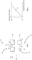
- Figure 3 illustrates an exemplary control schedule that may be used by the first control signal generator 50 to provide a variable geometry control signal.
- the schedule includes a single linear transfer function 54.
- the "max" configuration is representative of the variable geometry (i.e. outlet guide vanes) of the compressor 16 being in a position that exhibits the maximum flow capacity (i.e. a fully open position).
- the transfer function provides a gradual opening of the variable geometry in response to an increase in the corrected pack flow demand received from the pack demand adjustment module 48.
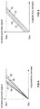
- Figure 4 depicts a further exemplary control schedule for the first control signal generator 50, which accommodates the diversion of air to the anti-icing system 45.
- This schedule comprises four transfer functions: a first (baseline) transfer function 55 that is selected when no air is diverted to the anti-icing system, a second transfer function 56 that is selected when air is diverted for engine anti-icing only, a third transfer function 57 that is selected when air is diverted for wing anti-icing only, and a fourth transfer function 58 that is selected when air is diverted for both wing and engine anti-icing.
- each transfer function 55, 56, 57, 58 provides a different relationship between the variable geometry control signal and the received corrected flow demand.
- the transfer functions 55, 56, 57, 58 differ in their gradient. All of the transfer functions 55, 56, 57, 58 provide a minimum variable geometry at the same corrected flow demand, but differ in the rate at which the variable geometry is opened with respect to corrected flow demand.
- the fourth transfer function 58 (representing both wing and engine anti-icing) reaches the maximum variable geometry at a lower corrected flow demand than the first (baseline) transfer function 55). In this way, the system 10 can ensure that air diverted to the anti-icing system 45 is compensated for by an increase in the airflow rate from the blower 11.
- the first control signal generator 50 may receive information regarding the operating state of the anti-icing system 45.
- the engine and wing anti-icing sub-systems may each comprise a sensor that detects the state of the sub-system and transmits this to the first control signal generator 50.
- a sensor may, for example, detect the opening of a valve for controlling air supply to the sub-system.
- control schedule of the first control signal generator 50 may include transfer functions that represent an operating condition one or more blowers of the system. This may be in combination with the anti-icing system state, or as an alternative. In this way, if one blower becomes inactive (e.g. due to an engine failure), the remaining blowers may compensate for the loss of airflow from the inactive blower.
- Figure 5 illustrates an alternative schedule to that shown in Figure 4 and described above and, accordingly, the transfer functions 55, 56, 57, 58 have been provided with the same reference numerals. Rather than differing in gradient, the transfer functions 55, 56, 57, 58 of Figure 5 differ by way of an offset constant. In this way, the rate of opening of the variable geometry in response to corrected flow demand is the same for each of the transfer functions 55, 56, 57, 58, but the offset constant means that, for example, the fourth transfer function 58 provides a greater variable geometry value than the other transfer functions 55, 56, 57 for a given corrected flow demand.
- Figure 6 illustrates an embodiment of the blower controller 25 that is similar to the embodiment shown in Figure 2 , except that the blower speed module 47' of Figure 3 takes the form of the variable geometry module 46 of Figure 2 , and the variable geometry module 46' of Figure 3 takes the form of the blower speed module 47 of Figure 2 .
- the blower speed module 47' of Figure 3 comprises a pack demand adjustment module 48 and the first control signal generator 50
- the variable geometry module 46' comprises a pack flow error module 51 and conversion module 53 of the second control signal generator (which, in this case, generates the variable geometry control signal 26).
- first control signal generator 50' of the embodiment of Figure 6 may be similar to those shown in figures 3 , 4 and 5 except that the output provided by the first control signal generator 50' is a blower speed rather than a variable geometry position.
- Figure 7 differs from the embodiment of Figure 2 in that the first control signal generator comprises first 63 and second 59 control schedules.
- the first control schedule 63 comprises a single transfer function (such as that shown in Figure 3 ).
- the first transfer function module 63 does not compensate for e.g. the diversion of airflow to the anti-icing system 45.
- the second schedule 59 also comprises a single transfer function that, as will be described below, compensates for external factors (such as the activation of the anti-icing system 45).
- the second control schedule 59 receives a valve opening signal 60 that is indicative of the state of a valve of the anti-icing system 45 (i.e. indicative of an opening size of the valve).
- the valve opening signal 60 may be indicative of the opening size of a wing and/or engine anti-icing valve.
- the second control schedule 59 may be similar to that show in figures 4 and 5 , except that the input of those transfer functions is the state of the valve and the output is a correction value (transmitted as a correction signal 61).
- the first signal generator 50" of the embodiment of Figure 7 further comprises a correction module 62 that determines the variable geometry control signal 26 based on the correction signal 61 and a preliminary control signal 64 received from the first control schedule 63.
- the correction signal "corrects" the preliminary variable geometry controls signal 64 so as to compensate for the provision of airflow to the anti-icing system 45.
Landscapes
- Engineering & Computer Science (AREA)
- Aviation & Aerospace Engineering (AREA)
- Mechanical Engineering (AREA)
- General Engineering & Computer Science (AREA)
- Health & Medical Sciences (AREA)
- General Health & Medical Sciences (AREA)
- Pulmonology (AREA)
- Chemical & Material Sciences (AREA)
- Combustion & Propulsion (AREA)
- Physics & Mathematics (AREA)
- Geometry (AREA)
- Control Of Positive-Displacement Air Blowers (AREA)
Applications Claiming Priority (1)
| Application Number | Priority Date | Filing Date | Title |
|---|---|---|---|
| GBGB1917966.2A GB201917966D0 (en) | 2019-12-09 | 2019-12-09 | Environmental control system |
Publications (2)
| Publication Number | Publication Date |
|---|---|
| EP3835558A1 true EP3835558A1 (de) | 2021-06-16 |
| EP3835558B1 EP3835558B1 (de) | 2023-01-04 |
Family
ID=69172101
Family Applications (1)
| Application Number | Title | Priority Date | Filing Date |
|---|---|---|---|
| EP20208164.2A Active EP3835558B1 (de) | 2019-12-09 | 2020-11-17 | Umweltkontrollsystem |
Country Status (3)
| Country | Link |
|---|---|
| US (1) | US20210171205A1 (de) |
| EP (1) | EP3835558B1 (de) |
| GB (1) | GB201917966D0 (de) |
Families Citing this family (2)
| Publication number | Priority date | Publication date | Assignee | Title |
|---|---|---|---|---|
| CN113309728B (zh) * | 2021-06-21 | 2023-02-28 | 中车大连机车研究所有限公司 | 磁悬浮鼓风机综合试验台 |
| GB202405968D0 (en) * | 2024-04-29 | 2024-06-12 | Rolls Royce Plc | Cabin blower control system and method |
Citations (4)
| Publication number | Priority date | Publication date | Assignee | Title |
|---|---|---|---|---|
| US4523517A (en) * | 1980-09-02 | 1985-06-18 | Lockhead Corporation | All electric environmental control system for advanced transport aircraft |
| EP1640673A2 (de) * | 2004-09-22 | 2006-03-29 | Hamilton Sundstrand Corporation | Klimaanlage mit einem elektrischangetriebenen Turbolader |
| US20160369705A1 (en) * | 2015-06-19 | 2016-12-22 | The Boeing Company | Aircraft bleed air and engine starter systems and related methods |
| EP3219620A1 (de) * | 2016-03-15 | 2017-09-20 | Hamilton Sundstrand Corporation | Zapfluftsystem eines triebwerks mit motorisch angetriebenem verdichter |
Family Cites Families (6)
| Publication number | Priority date | Publication date | Assignee | Title |
|---|---|---|---|---|
| US4546939A (en) * | 1982-05-27 | 1985-10-15 | Lockheed Corporation | Energy efficient ECS powered by a variable voltage/variable frequency power system |
| EP3297917B1 (de) * | 2015-05-22 | 2023-10-04 | Bombardier Inc. | Luftströmungsregelung in der kabine eines flugzeuges |
| US10144521B2 (en) * | 2015-08-04 | 2018-12-04 | Hamilton Sundstrand Corporation | Electric compressor for use with a wing anti-ice system |
| JP6654483B2 (ja) * | 2016-03-24 | 2020-02-26 | 三菱航空機株式会社 | 航空機の防氷システム、それを備えた航空機、防氷システム制御プログラム、および防氷システムの制御方法 |
| US10239626B2 (en) * | 2016-03-29 | 2019-03-26 | Gulfstream Aerospace Corporation | Arrangements and methods for supplying heated air to a wing anti-icing system |
| GB201908379D0 (en) * | 2019-05-03 | 2019-07-24 | Rolls Royce Plc | A system for an aircraft |
-
2019
- 2019-12-09 GB GBGB1917966.2A patent/GB201917966D0/en not_active Ceased
-
2020
- 2020-11-17 EP EP20208164.2A patent/EP3835558B1/de active Active
- 2020-12-04 US US17/112,249 patent/US20210171205A1/en not_active Abandoned
Patent Citations (4)
| Publication number | Priority date | Publication date | Assignee | Title |
|---|---|---|---|---|
| US4523517A (en) * | 1980-09-02 | 1985-06-18 | Lockhead Corporation | All electric environmental control system for advanced transport aircraft |
| EP1640673A2 (de) * | 2004-09-22 | 2006-03-29 | Hamilton Sundstrand Corporation | Klimaanlage mit einem elektrischangetriebenen Turbolader |
| US20160369705A1 (en) * | 2015-06-19 | 2016-12-22 | The Boeing Company | Aircraft bleed air and engine starter systems and related methods |
| EP3219620A1 (de) * | 2016-03-15 | 2017-09-20 | Hamilton Sundstrand Corporation | Zapfluftsystem eines triebwerks mit motorisch angetriebenem verdichter |
Also Published As
| Publication number | Publication date |
|---|---|
| US20210171205A1 (en) | 2021-06-10 |
| EP3835558B1 (de) | 2023-01-04 |
| GB201917966D0 (en) | 2020-01-22 |
Similar Documents
| Publication | Publication Date | Title |
|---|---|---|
| EP2862803B1 (de) | Pneumatisches System für ein Flugzeug | |
| US10752365B2 (en) | Method and device for thermal control of a plurality of cabins of a vehicle | |
| EP2955334B1 (de) | Verfahren und vorrichtung zur steuerung eines verdichters eines gasturbinenmotors | |
| EP1640673B1 (de) | Klimaanlage mit einem elektrischangetriebenen Turbolader | |
| US9879610B2 (en) | Pnuematic system for an aircraft | |
| CA2768929C (en) | Environmental control system supply precooler bypass | |
| CN104912835B (zh) | 涡轮压缩机系统、航空器及从航空器发动机提取能量的方法 | |
| EP2597036B1 (de) | Luftkreislaufsystem mit gemischtem Strom für Flugzeugklimaanlage | |
| US9841038B2 (en) | Controlling method and system for compressed air supply to a pneumatic network, in particular in an aircraft | |
| CN110844089A (zh) | 用于混合电动系统的前馈负载感测 | |
| EP3667044B1 (de) | System und verfahren zur selektiven modulation der strömung von zapfluft, die zur hochdruckturbinenstufenkühlung in einem nutzturbinentriebwerk verwendet wird | |
| CN116464554B (zh) | 用于燃气涡轮发动机的排放流组件 | |
| JP2012246928A (ja) | 適応出力熱管理システム | |
| EP3862553B1 (de) | Dosierpumpensystem | |
| EP3608228B1 (de) | Angetriebene vorkühlergebläseanordnung | |
| CN116464555B (zh) | 用于燃气涡轮发动机的排放流组件 | |
| US20160053721A1 (en) | Gas turbine engine and method of operation | |
| EP3712414B1 (de) | Druckluftsystem | |
| EP3835558B1 (de) | Umweltkontrollsystem | |
| CN116464553A (zh) | 用于燃气涡轮发动机的排放流组件 | |
| US11078838B2 (en) | Gas turbine engine compressor control method | |
| EP3901440B1 (de) | System und verfahren zur motordrehzahlregelung | |
| CN112937885A (zh) | 一种利用辅助动力装置进行引气的引气系统以及引气控制方法 | |
| CN116464552B (zh) | 用于燃气涡轮发动机的排放流组件 | |
| US12264631B2 (en) | System and method for synchrophasing a propulsion system using electric machines |
Legal Events
| Date | Code | Title | Description |
|---|---|---|---|
| PUAI | Public reference made under article 153(3) epc to a published international application that has entered the european phase |
Free format text: ORIGINAL CODE: 0009012 |
|
| STAA | Information on the status of an ep patent application or granted ep patent |
Free format text: STATUS: THE APPLICATION HAS BEEN PUBLISHED |
|
| AK | Designated contracting states |
Kind code of ref document: A1 Designated state(s): AL AT BE BG CH CY CZ DE DK EE ES FI FR GB GR HR HU IE IS IT LI LT LU LV MC MK MT NL NO PL PT RO RS SE SI SK SM TR |
|
| STAA | Information on the status of an ep patent application or granted ep patent |
Free format text: STATUS: REQUEST FOR EXAMINATION WAS MADE |
|
| 17P | Request for examination filed |
Effective date: 20211210 |
|
| RBV | Designated contracting states (corrected) |
Designated state(s): AL AT BE BG CH CY CZ DE DK EE ES FI FR GB GR HR HU IE IS IT LI LT LU LV MC MK MT NL NO PL PT RO RS SE SI SK SM TR |
|
| GRAP | Despatch of communication of intention to grant a patent |
Free format text: ORIGINAL CODE: EPIDOSNIGR1 |
|
| STAA | Information on the status of an ep patent application or granted ep patent |
Free format text: STATUS: GRANT OF PATENT IS INTENDED |
|
| GRAS | Grant fee paid |
Free format text: ORIGINAL CODE: EPIDOSNIGR3 |
|
| INTG | Intention to grant announced |
Effective date: 20221013 |
|
| RIC1 | Information provided on ipc code assigned before grant |
Ipc: B64D 15/04 20060101ALI20220930BHEP Ipc: B64D 13/06 20060101ALI20220930BHEP Ipc: F02C 6/08 20060101AFI20220930BHEP |
|
| GRAA | (expected) grant |
Free format text: ORIGINAL CODE: 0009210 |
|
| STAA | Information on the status of an ep patent application or granted ep patent |
Free format text: STATUS: THE PATENT HAS BEEN GRANTED |
|
| AK | Designated contracting states |
Kind code of ref document: B1 Designated state(s): AL AT BE BG CH CY CZ DE DK EE ES FI FR GB GR HR HU IE IS IT LI LT LU LV MC MK MT NL NO PL PT RO RS SE SI SK SM TR |
|
| REG | Reference to a national code |
Ref country code: GB Ref legal event code: FG4D |
|
| REG | Reference to a national code |
Ref country code: DE Ref legal event code: R096 Ref document number: 602020007345 Country of ref document: DE |
|
| REG | Reference to a national code |
Ref country code: CH Ref legal event code: EP |
|
| REG | Reference to a national code |
Ref country code: AT Ref legal event code: REF Ref document number: 1542079 Country of ref document: AT Kind code of ref document: T Effective date: 20230115 |
|
| REG | Reference to a national code |
Ref country code: IE Ref legal event code: FG4D |
|
| REG | Reference to a national code |
Ref country code: LT Ref legal event code: MG9D |
|
| REG | Reference to a national code |
Ref country code: NL Ref legal event code: MP Effective date: 20230104 |
|
| REG | Reference to a national code |
Ref country code: AT Ref legal event code: MK05 Ref document number: 1542079 Country of ref document: AT Kind code of ref document: T Effective date: 20230104 |
|
| PG25 | Lapsed in a contracting state [announced via postgrant information from national office to epo] |
Ref country code: NL Free format text: LAPSE BECAUSE OF FAILURE TO SUBMIT A TRANSLATION OF THE DESCRIPTION OR TO PAY THE FEE WITHIN THE PRESCRIBED TIME-LIMIT Effective date: 20230104 |
|
| P01 | Opt-out of the competence of the unified patent court (upc) registered |
Effective date: 20230528 |
|
| PG25 | Lapsed in a contracting state [announced via postgrant information from national office to epo] |
Ref country code: RS Free format text: LAPSE BECAUSE OF FAILURE TO SUBMIT A TRANSLATION OF THE DESCRIPTION OR TO PAY THE FEE WITHIN THE PRESCRIBED TIME-LIMIT Effective date: 20230104 Ref country code: PT Free format text: LAPSE BECAUSE OF FAILURE TO SUBMIT A TRANSLATION OF THE DESCRIPTION OR TO PAY THE FEE WITHIN THE PRESCRIBED TIME-LIMIT Effective date: 20230504 Ref country code: NO Free format text: LAPSE BECAUSE OF FAILURE TO SUBMIT A TRANSLATION OF THE DESCRIPTION OR TO PAY THE FEE WITHIN THE PRESCRIBED TIME-LIMIT Effective date: 20230404 Ref country code: LV Free format text: LAPSE BECAUSE OF FAILURE TO SUBMIT A TRANSLATION OF THE DESCRIPTION OR TO PAY THE FEE WITHIN THE PRESCRIBED TIME-LIMIT Effective date: 20230104 Ref country code: LT Free format text: LAPSE BECAUSE OF FAILURE TO SUBMIT A TRANSLATION OF THE DESCRIPTION OR TO PAY THE FEE WITHIN THE PRESCRIBED TIME-LIMIT Effective date: 20230104 Ref country code: HR Free format text: LAPSE BECAUSE OF FAILURE TO SUBMIT A TRANSLATION OF THE DESCRIPTION OR TO PAY THE FEE WITHIN THE PRESCRIBED TIME-LIMIT Effective date: 20230104 Ref country code: ES Free format text: LAPSE BECAUSE OF FAILURE TO SUBMIT A TRANSLATION OF THE DESCRIPTION OR TO PAY THE FEE WITHIN THE PRESCRIBED TIME-LIMIT Effective date: 20230104 Ref country code: AT Free format text: LAPSE BECAUSE OF FAILURE TO SUBMIT A TRANSLATION OF THE DESCRIPTION OR TO PAY THE FEE WITHIN THE PRESCRIBED TIME-LIMIT Effective date: 20230104 |
|
| PG25 | Lapsed in a contracting state [announced via postgrant information from national office to epo] |
Ref country code: SE Free format text: LAPSE BECAUSE OF FAILURE TO SUBMIT A TRANSLATION OF THE DESCRIPTION OR TO PAY THE FEE WITHIN THE PRESCRIBED TIME-LIMIT Effective date: 20230104 Ref country code: PL Free format text: LAPSE BECAUSE OF FAILURE TO SUBMIT A TRANSLATION OF THE DESCRIPTION OR TO PAY THE FEE WITHIN THE PRESCRIBED TIME-LIMIT Effective date: 20230104 Ref country code: IS Free format text: LAPSE BECAUSE OF FAILURE TO SUBMIT A TRANSLATION OF THE DESCRIPTION OR TO PAY THE FEE WITHIN THE PRESCRIBED TIME-LIMIT Effective date: 20230504 Ref country code: GR Free format text: LAPSE BECAUSE OF FAILURE TO SUBMIT A TRANSLATION OF THE DESCRIPTION OR TO PAY THE FEE WITHIN THE PRESCRIBED TIME-LIMIT Effective date: 20230405 Ref country code: FI Free format text: LAPSE BECAUSE OF FAILURE TO SUBMIT A TRANSLATION OF THE DESCRIPTION OR TO PAY THE FEE WITHIN THE PRESCRIBED TIME-LIMIT Effective date: 20230104 |
|
| REG | Reference to a national code |
Ref country code: DE Ref legal event code: R097 Ref document number: 602020007345 Country of ref document: DE |
|
| PG25 | Lapsed in a contracting state [announced via postgrant information from national office to epo] |
Ref country code: SM Free format text: LAPSE BECAUSE OF FAILURE TO SUBMIT A TRANSLATION OF THE DESCRIPTION OR TO PAY THE FEE WITHIN THE PRESCRIBED TIME-LIMIT Effective date: 20230104 Ref country code: RO Free format text: LAPSE BECAUSE OF FAILURE TO SUBMIT A TRANSLATION OF THE DESCRIPTION OR TO PAY THE FEE WITHIN THE PRESCRIBED TIME-LIMIT Effective date: 20230104 Ref country code: EE Free format text: LAPSE BECAUSE OF FAILURE TO SUBMIT A TRANSLATION OF THE DESCRIPTION OR TO PAY THE FEE WITHIN THE PRESCRIBED TIME-LIMIT Effective date: 20230104 Ref country code: DK Free format text: LAPSE BECAUSE OF FAILURE TO SUBMIT A TRANSLATION OF THE DESCRIPTION OR TO PAY THE FEE WITHIN THE PRESCRIBED TIME-LIMIT Effective date: 20230104 Ref country code: CZ Free format text: LAPSE BECAUSE OF FAILURE TO SUBMIT A TRANSLATION OF THE DESCRIPTION OR TO PAY THE FEE WITHIN THE PRESCRIBED TIME-LIMIT Effective date: 20230104 |
|
| PLBE | No opposition filed within time limit |
Free format text: ORIGINAL CODE: 0009261 |
|
| STAA | Information on the status of an ep patent application or granted ep patent |
Free format text: STATUS: NO OPPOSITION FILED WITHIN TIME LIMIT |
|
| PG25 | Lapsed in a contracting state [announced via postgrant information from national office to epo] |
Ref country code: SK Free format text: LAPSE BECAUSE OF FAILURE TO SUBMIT A TRANSLATION OF THE DESCRIPTION OR TO PAY THE FEE WITHIN THE PRESCRIBED TIME-LIMIT Effective date: 20230104 |
|
| 26N | No opposition filed |
Effective date: 20231005 |
|
| PG25 | Lapsed in a contracting state [announced via postgrant information from national office to epo] |
Ref country code: SI Free format text: LAPSE BECAUSE OF FAILURE TO SUBMIT A TRANSLATION OF THE DESCRIPTION OR TO PAY THE FEE WITHIN THE PRESCRIBED TIME-LIMIT Effective date: 20230104 |
|
| PG25 | Lapsed in a contracting state [announced via postgrant information from national office to epo] |
Ref country code: IT Free format text: LAPSE BECAUSE OF FAILURE TO SUBMIT A TRANSLATION OF THE DESCRIPTION OR TO PAY THE FEE WITHIN THE PRESCRIBED TIME-LIMIT Effective date: 20230104 |
|
| REG | Reference to a national code |
Ref country code: CH Ref legal event code: PL |
|
| PG25 | Lapsed in a contracting state [announced via postgrant information from national office to epo] |
Ref country code: MC Free format text: LAPSE BECAUSE OF FAILURE TO SUBMIT A TRANSLATION OF THE DESCRIPTION OR TO PAY THE FEE WITHIN THE PRESCRIBED TIME-LIMIT Effective date: 20230104 |
|
| PG25 | Lapsed in a contracting state [announced via postgrant information from national office to epo] |
Ref country code: LU Free format text: LAPSE BECAUSE OF NON-PAYMENT OF DUE FEES Effective date: 20231117 |
|
| PG25 | Lapsed in a contracting state [announced via postgrant information from national office to epo] |
Ref country code: CH Free format text: LAPSE BECAUSE OF NON-PAYMENT OF DUE FEES Effective date: 20231130 |
|
| PG25 | Lapsed in a contracting state [announced via postgrant information from national office to epo] |
Ref country code: MC Free format text: LAPSE BECAUSE OF FAILURE TO SUBMIT A TRANSLATION OF THE DESCRIPTION OR TO PAY THE FEE WITHIN THE PRESCRIBED TIME-LIMIT Effective date: 20230104 Ref country code: LU Free format text: LAPSE BECAUSE OF NON-PAYMENT OF DUE FEES Effective date: 20231117 Ref country code: CH Free format text: LAPSE BECAUSE OF NON-PAYMENT OF DUE FEES Effective date: 20231130 |
|
| REG | Reference to a national code |
Ref country code: BE Ref legal event code: MM Effective date: 20231130 |
|
| REG | Reference to a national code |
Ref country code: IE Ref legal event code: MM4A |
|
| PG25 | Lapsed in a contracting state [announced via postgrant information from national office to epo] |
Ref country code: IE Free format text: LAPSE BECAUSE OF NON-PAYMENT OF DUE FEES Effective date: 20231117 |
|
| PG25 | Lapsed in a contracting state [announced via postgrant information from national office to epo] |
Ref country code: BE Free format text: LAPSE BECAUSE OF NON-PAYMENT OF DUE FEES Effective date: 20231130 |
|
| PG25 | Lapsed in a contracting state [announced via postgrant information from national office to epo] |
Ref country code: IE Free format text: LAPSE BECAUSE OF NON-PAYMENT OF DUE FEES Effective date: 20231117 Ref country code: BE Free format text: LAPSE BECAUSE OF NON-PAYMENT OF DUE FEES Effective date: 20231130 |
|
| PG25 | Lapsed in a contracting state [announced via postgrant information from national office to epo] |
Ref country code: BG Free format text: LAPSE BECAUSE OF FAILURE TO SUBMIT A TRANSLATION OF THE DESCRIPTION OR TO PAY THE FEE WITHIN THE PRESCRIBED TIME-LIMIT Effective date: 20230104 |
|
| PG25 | Lapsed in a contracting state [announced via postgrant information from national office to epo] |
Ref country code: BG Free format text: LAPSE BECAUSE OF FAILURE TO SUBMIT A TRANSLATION OF THE DESCRIPTION OR TO PAY THE FEE WITHIN THE PRESCRIBED TIME-LIMIT Effective date: 20230104 |
|
| PG25 | Lapsed in a contracting state [announced via postgrant information from national office to epo] |
Ref country code: CY Free format text: LAPSE BECAUSE OF FAILURE TO SUBMIT A TRANSLATION OF THE DESCRIPTION OR TO PAY THE FEE WITHIN THE PRESCRIBED TIME-LIMIT; INVALID AB INITIO Effective date: 20201117 |
|
| PG25 | Lapsed in a contracting state [announced via postgrant information from national office to epo] |
Ref country code: HU Free format text: LAPSE BECAUSE OF FAILURE TO SUBMIT A TRANSLATION OF THE DESCRIPTION OR TO PAY THE FEE WITHIN THE PRESCRIBED TIME-LIMIT; INVALID AB INITIO Effective date: 20201117 |
|
| PG25 | Lapsed in a contracting state [announced via postgrant information from national office to epo] |
Ref country code: TR Free format text: LAPSE BECAUSE OF FAILURE TO SUBMIT A TRANSLATION OF THE DESCRIPTION OR TO PAY THE FEE WITHIN THE PRESCRIBED TIME-LIMIT Effective date: 20230104 |
|
| PGFP | Annual fee paid to national office [announced via postgrant information from national office to epo] |
Ref country code: DE Payment date: 20251126 Year of fee payment: 6 |
|
| PGFP | Annual fee paid to national office [announced via postgrant information from national office to epo] |
Ref country code: GB Payment date: 20251125 Year of fee payment: 6 |
|
| PGFP | Annual fee paid to national office [announced via postgrant information from national office to epo] |
Ref country code: FR Payment date: 20251124 Year of fee payment: 6 |