EP3835560A1 - Détection de débris d'objets étrangers (fod) basée sur lidar pour moteurs à turbine à gaz - Google Patents
Détection de débris d'objets étrangers (fod) basée sur lidar pour moteurs à turbine à gaz Download PDFInfo
- Publication number
- EP3835560A1 EP3835560A1 EP20212584.5A EP20212584A EP3835560A1 EP 3835560 A1 EP3835560 A1 EP 3835560A1 EP 20212584 A EP20212584 A EP 20212584A EP 3835560 A1 EP3835560 A1 EP 3835560A1
- Authority
- EP
- European Patent Office
- Prior art keywords
- fod
- transmitters
- gas turbine
- sensor assembly
- transceivers
- Prior art date
- Legal status (The legal status is an assumption and is not a legal conclusion. Google has not performed a legal analysis and makes no representation as to the accuracy of the status listed.)
- Granted
Links
Images


Classifications
-
- F—MECHANICAL ENGINEERING; LIGHTING; HEATING; WEAPONS; BLASTING
- F02—COMBUSTION ENGINES; HOT-GAS OR COMBUSTION-PRODUCT ENGINE PLANTS
- F02C—GAS-TURBINE PLANTS; AIR INTAKES FOR JET-PROPULSION PLANTS; CONTROLLING FUEL SUPPLY IN AIR-BREATHING JET-PROPULSION PLANTS
- F02C7/00—Features, components parts, details or accessories, not provided for in, or of interest apart form groups F02C1/00 - F02C6/00; Air intakes for jet-propulsion plants
- F02C7/04—Air intakes for gas-turbine plants or jet-propulsion plants
- F02C7/05—Air intakes for gas-turbine plants or jet-propulsion plants having provisions for obviating the penetration of damaging objects or particles
-
- F—MECHANICAL ENGINEERING; LIGHTING; HEATING; WEAPONS; BLASTING
- F01—MACHINES OR ENGINES IN GENERAL; ENGINE PLANTS IN GENERAL; STEAM ENGINES
- F01D—NON-POSITIVE DISPLACEMENT MACHINES OR ENGINES, e.g. STEAM TURBINES
- F01D17/00—Regulating or controlling by varying flow
- F01D17/20—Devices dealing with sensing elements or final actuators or transmitting means between them, e.g. power-assisted
-
- F—MECHANICAL ENGINEERING; LIGHTING; HEATING; WEAPONS; BLASTING
- F01—MACHINES OR ENGINES IN GENERAL; ENGINE PLANTS IN GENERAL; STEAM ENGINES
- F01D—NON-POSITIVE DISPLACEMENT MACHINES OR ENGINES, e.g. STEAM TURBINES
- F01D21/00—Shutting-down of machines or engines, e.g. in emergency; Regulating, controlling, or safety means not otherwise provided for
- F01D21/10—Shutting-down of machines or engines, e.g. in emergency; Regulating, controlling, or safety means not otherwise provided for responsive to unwanted deposits on blades, in working-fluid conduits or the like
-
- F—MECHANICAL ENGINEERING; LIGHTING; HEATING; WEAPONS; BLASTING
- F02—COMBUSTION ENGINES; HOT-GAS OR COMBUSTION-PRODUCT ENGINE PLANTS
- F02C—GAS-TURBINE PLANTS; AIR INTAKES FOR JET-PROPULSION PLANTS; CONTROLLING FUEL SUPPLY IN AIR-BREATHING JET-PROPULSION PLANTS
- F02C7/00—Features, components parts, details or accessories, not provided for in, or of interest apart form groups F02C1/00 - F02C6/00; Air intakes for jet-propulsion plants
- F02C7/04—Air intakes for gas-turbine plants or jet-propulsion plants
- F02C7/057—Control or regulation
-
- G—PHYSICS
- G01—MEASURING; TESTING
- G01S—RADIO DIRECTION-FINDING; RADIO NAVIGATION; DETERMINING DISTANCE OR VELOCITY BY USE OF RADIO WAVES; LOCATING OR PRESENCE-DETECTING BY USE OF THE REFLECTION OR RERADIATION OF RADIO WAVES; ANALOGOUS ARRANGEMENTS USING OTHER WAVES
- G01S17/00—Systems using the reflection or reradiation of electromagnetic waves other than radio waves, e.g. lidar systems
- G01S17/02—Systems using the reflection of electromagnetic waves other than radio waves
- G01S17/04—Systems determining the presence of a target
-
- G—PHYSICS
- G01—MEASURING; TESTING
- G01S—RADIO DIRECTION-FINDING; RADIO NAVIGATION; DETERMINING DISTANCE OR VELOCITY BY USE OF RADIO WAVES; LOCATING OR PRESENCE-DETECTING BY USE OF THE REFLECTION OR RERADIATION OF RADIO WAVES; ANALOGOUS ARRANGEMENTS USING OTHER WAVES
- G01S17/00—Systems using the reflection or reradiation of electromagnetic waves other than radio waves, e.g. lidar systems
- G01S17/88—Lidar systems specially adapted for specific applications
-
- G—PHYSICS
- G01—MEASURING; TESTING
- G01S—RADIO DIRECTION-FINDING; RADIO NAVIGATION; DETERMINING DISTANCE OR VELOCITY BY USE OF RADIO WAVES; LOCATING OR PRESENCE-DETECTING BY USE OF THE REFLECTION OR RERADIATION OF RADIO WAVES; ANALOGOUS ARRANGEMENTS USING OTHER WAVES
- G01S7/00—Details of systems according to groups G01S13/00, G01S15/00, G01S17/00
- G01S7/48—Details of systems according to groups G01S13/00, G01S15/00, G01S17/00 of systems according to group G01S17/00
- G01S7/481—Constructional features, e.g. arrangements of optical elements
- G01S7/4814—Constructional features, e.g. arrangements of optical elements of transmitters alone
- G01S7/4815—Constructional features, e.g. arrangements of optical elements of transmitters alone using multiple transmitters
-
- G—PHYSICS
- G01—MEASURING; TESTING
- G01V—GEOPHYSICS; GRAVITATIONAL MEASUREMENTS; DETECTING MASSES OR OBJECTS; TAGS
- G01V8/00—Prospecting or detecting by optical means
- G01V8/10—Detecting, e.g. by using light barriers
- G01V8/12—Detecting, e.g. by using light barriers using one transmitter and one receiver
-
- F—MECHANICAL ENGINEERING; LIGHTING; HEATING; WEAPONS; BLASTING
- F05—INDEXING SCHEMES RELATING TO ENGINES OR PUMPS IN VARIOUS SUBCLASSES OF CLASSES F01-F04
- F05D—INDEXING SCHEME FOR ASPECTS RELATING TO NON-POSITIVE-DISPLACEMENT MACHINES OR ENGINES, GAS-TURBINES OR JET-PROPULSION PLANTS
- F05D2260/00—Function
- F05D2260/60—Fluid transfer
- F05D2260/607—Preventing clogging or obstruction of flow paths by dirt, dust, or foreign particles
-
- F—MECHANICAL ENGINEERING; LIGHTING; HEATING; WEAPONS; BLASTING
- F05—INDEXING SCHEMES RELATING TO ENGINES OR PUMPS IN VARIOUS SUBCLASSES OF CLASSES F01-F04
- F05D—INDEXING SCHEME FOR ASPECTS RELATING TO NON-POSITIVE-DISPLACEMENT MACHINES OR ENGINES, GAS-TURBINES OR JET-PROPULSION PLANTS
- F05D2270/00—Control
- F05D2270/80—Devices generating input signals, e.g. transducers, sensors, cameras or strain gauges
- F05D2270/804—Optical devices
-
- Y—GENERAL TAGGING OF NEW TECHNOLOGICAL DEVELOPMENTS; GENERAL TAGGING OF CROSS-SECTIONAL TECHNOLOGIES SPANNING OVER SEVERAL SECTIONS OF THE IPC; TECHNICAL SUBJECTS COVERED BY FORMER USPC CROSS-REFERENCE ART COLLECTIONS [XRACs] AND DIGESTS
- Y02—TECHNOLOGIES OR APPLICATIONS FOR MITIGATION OR ADAPTATION AGAINST CLIMATE CHANGE
- Y02T—CLIMATE CHANGE MITIGATION TECHNOLOGIES RELATED TO TRANSPORTATION
- Y02T50/00—Aeronautics or air transport
- Y02T50/60—Efficient propulsion technologies, e.g. for aircraft
Definitions
- This disclosure relates generally to gas turbine engines, and more particularly to a foreign object debris (FOD) detection system for gas-turbine engines.
- FOD foreign object debris
- Gas turbine engines typically include a fan section to drive inflowing air, a compressor section to pressurize inflowing air, a combustor section to burn a fuel in the presence of the pressurized air, and a turbine section to extract energy from the resulting combustion gases.
- the fan section may include a plurality of fan blades coupled to a fan hub. Forward of the fan section typically includes an inlet. During operation of a gas turbine engine, foreign object debris (FOD) may enter the inlet and/or enter a gas turbine engine.
- FOD foreign object debris
- the gas turbine engine may comprise a nacelle at least partially defining a boundary of an inlet of the gas turbine engine; a fan section disposed aft of the inlet; and a foreign object debris (FOD) detection system mounted to a radially inner surface of the nacelle; the FOD detection system comprising a light detection and ranging (LiDAR) sensor assembly configured to scan a pre-determined volume within the inlet.
- a nacelle at least partially defining a boundary of an inlet of the gas turbine engine
- a fan section disposed aft of the inlet
- a foreign object debris (FOD) detection system mounted to a radially inner surface of the nacelle
- the FOD detection system comprising a light detection and ranging (LiDAR) sensor assembly configured to scan a pre-determined volume within the inlet.
- LiDAR light detection and ranging
- the gas turbine engine may further comprise an FOD detection processor electrically coupled to the LiDAR sensor assembly, the FOD detection processor configured to transfer a control signal to increase a resolution in a local area of a tracking zone in response to detecting FOD in the local area.
- the LiDAR sensor assembly may comprise a single transceiver configured to scan the pre-determined volume within the inlet.
- the LiDAR sensor assembly may comprise a plurality of transceivers, wherein each transceiver in the plurality of transceivers is fixed, the plurality of transceivers configured to scan the pre-determined volume.
- the plurality of transceivers may be disposed in an array.
- the LiDAR sensor assembly may further comprise a plurality of transmitters and a receiver, each transmitter in the plurality of transmitters configured to emit a pulsed beam sequentially following an adjacent transmitter in the plurality of transmitters.
- the plurality of transmitters may be disposed in an array.
- the LiDAR sensor assembly may further comprise a plurality of receivers and a transmitter, wherein each receiver is configured to detect a reflection from a pre-determined direction.
- the plurality of receivers may be disposed in an array.
- a gas turbine engine is disclosed herein.
- the gas turbine engine may comprise: an engine core; an inlet disposed forward of the engine core, the inlet comprising a centerbody; and a foreign object debris (FOD) detection system mounted to the centerbody; the FOD detection system comprising a first light detection and ranging (LiDAR) sensor assembly configured to scan a first pre-determined volume within the inlet, the first pre-determined volume defining at least one of a first volume forward of the centerbody and a second volume radially outward of the centerbody.
- LiDAR light detection and ranging
- the gas turbine engine may further comprise a second LiDAR sensor assembly coupled to the centerbody.
- the first pre-determined volume may be the first volume.
- the second LiDAR sensor assembly may be configured to scan a second pre-determined volume, and the second pre-determined volume may be the second volume.
- the first LiDAR sensor assembly may be configured to detect and track FOD during operation of the gas turbine engine.
- the gas turbine engine may further comprise an FOD detection processor electrically coupled to the first LiDAR sensor assembly, and the first LiDAR sensor assembly may comprise a plurality of transceivers.
- the FOD detection processor may be configured to increase a first resolution of a first portion of transceivers in the plurality of transceivers in response to a transceiver in the plurality of transceivers detecting the FOD.
- the FOD detection processor may be configured to decrease a second resolution of a second portion of transceivers in the plurality of transceivers in response to the transceiver in the plurality of transceivers detecting the FOD.
- the second portion of transceivers may be different than the first portion of transceivers.
- the gas turbine engine may further comprise an FOD detection processor electrically coupled to the first LiDAR sensor assembly.
- the first LiDAR sensor assembly may comprise a plurality of transmitters and a receiver.
- the FOD detection processor may be configured to increase a first resolution of a first portion of transmitters in the plurality of transmitters in response to a transmitter in the plurality of transmitters detecting the FOD.
- the FOD detection processor may be configured to decrease a second resolution of a second portion of transmitters in the plurality of transmitters in response to the transmitter in the plurality of transmitters detecting the FOD.
- the second portion of transmitters may be different than the first portion of transmitters.
- a method of using a foreign object debris (FOD) detection system for a gas turbine engine is disclosed herein.
- the method may comprise: detecting FOD in an inlet of the gas turbine engine; increasing a first resolution of a first portion of transmitters or receivers in a plurality of transmitters or transceivers; and tracking the FOD through a pre-determined volume defined by the plurality of transmitters or transceivers.
- FOD foreign object debris
- the method may further comprise decreasing a second resolution of a second portion of transmitters or transceivers in the plurality of transmitters or transceivers.
- the second portion of transmitters or transceivers being different than the first portion of transmitters or transceivers.
- any of the method or process descriptions may be executed in any order and are not necessarily limited to the order presented.
- any reference to singular includes plural embodiments, and any reference to more than one component or step may include a singular embodiment or step.
- any reference to attached, fixed, coupled, connected or the like may include permanent, removable, temporary, partial, full and/or any other possible attachment option.
- any reference to without contact (or similar phrases) may also include reduced contact or minimal contact. Surface shading lines may be used throughout the figures to denote different parts but not necessarily to denote the same or different materials.
- electrosenor communication means communication of electronic signals with physical coupling (e.g., “electrical communication” or “electrically coupled”) or without physical coupling and via an electromagnetic field (e.g., “inductive communication” or “inductively coupled” or “inductive coupling”).
- transmit may include sending electronic data from one system component to another via electronic communication between the components.
- electronic data may include encompassing information such as commands, queries, files, data for storage, and the like in digital or any other form.
- tail refers to the direction associated with the tail (e.g., the back end) of an aircraft, or generally, to the direction of exhaust of the gas turbine.
- forward refers to the direction associated with the nose (e.g., the front end) of an aircraft, or generally, to the direction of flight or motion.
- a gas turbine engine 120 is disclosed.
- “aft” refers to the direction associated with a tail (e.g., the back end) of an aircraft, or generally, to the direction of exhaust of gas turbine engine 120.
- “forward” refers to the direction associated with a nose (e.g., the front end) of the aircraft, or generally, to the direction of flight or motion.
- An A-R-C axis has been included throughout the figures to illustrate the axial (A), radial (R) and circumferential (C) directions.
- axial axis A spans parallel to engine central longitudinal axis A-A'.
- radially inward refers to the negative R direction towards engine central longitudinal axis A-A'
- radially outward refers to the R direction away from engine central longitudinal axis A-A'.
- Gas turbine engine 120 may comprise a two-spool turbofan that generally incorporates a fan section 122, a compressor section 124, a combustor section 126, and a turbine section 128.
- fan section 122 may drive air along a bypass flow-path B
- compressor section 124 may further drive air along a core flow-path C for compression and communication into combustor section 126, before expansion through turbine section 128.
- FIG. 1A provides a general understanding of the sections in a gas turbine engine, and is not intended to limit the disclosure.
- an intermediate spool includes an intermediate pressure compressor ("IPC") between a low pressure compressor (“LPC”) and a high pressure compressor (“HPC”), and an intermediate pressure turbine (“IPT”) between the high pressure turbine (“HPT”) and the low pressure turbine (“LPT”).
- IPC intermediate pressure compressor
- HPC low pressure compressor
- HPC high pressure compressor
- IPT intermediate pressure turbine
- gas turbine engine 120 may comprise a low speed spool 130 and a high speed spool 132 mounted for rotation about an engine central longitudinal axis A-A' relative to an engine static structure 136 via one or more bearing systems 138 (shown as, for example, bearing system 138-1 and bearing system 138-2 in FIG. 1A ). It should be understood that various bearing systems 138 at various locations may alternatively or additionally be provided, including, for example, bearing system 138, bearing system 138-1, and/or bearing system 138-2.
- low speed spool 130 may comprise an inner shaft 140 that interconnects a fan 142, a low pressure (or a first) compressor section 144, and a low pressure (or a second) turbine section 146.
- Inner shaft 140 may be connected to fan 142 through a geared architecture 148 that can drive fan 142 at a lower speed than low speed spool 130.
- Geared architecture 148 may comprise a gear assembly 160 enclosed within a gear housing 162.
- Gear assembly 160 may couple inner shaft 140 to a rotating fan structure.
- High speed spool 132 may comprise an outer shaft 150 that interconnects a high pressure compressor (“HPC") 152 (e.g., a second compressor section) and high pressure (or a first) turbine section 154.
- HPC high pressure compressor
- a combustor 156 may be located between HPC 152 and high pressure turbine 154.
- a mid-turbine frame 157 of engine static structure 136 may be located generally between high pressure turbine 154 and low pressure turbine 146.
- Mid-turbine frame 157 may support one or more bearing systems 138 in turbine section 128.
- Inner shaft 140 and outer shaft 150 may be concentric and may rotate via bearing systems 138 about engine central longitudinal axis A-A'.
- a "high pressure" compressor and/or turbine may experience a higher pressure than a corresponding "low pressure” compressor and/or turbine.
- the air along core airflow C may be compressed by low pressure compressor 144 and HPC 152, mixed and burned with fuel in combustor 156, and expanded over high pressure turbine 154 and low pressure turbine 146.
- Mid-turbine frame 157 may comprise airfoils 159 located in core airflow path C.
- Low pressure turbine 146 and high pressure turbine 154 may rotationally drive low speed spool 130 and high speed spool 132, respectively, in response to the expansion.
- gas turbine engine 120 may comprise a high-bypass ratio geared aircraft engine.
- the bypass ratio of gas turbine engine 120 may also be greater than ten (10:1).
- Geared architecture 148 may be an epicyclic gear train, such as a star gear system (sun gear in meshing engagement with a plurality of star gears supported by a carrier and in meshing engagement with a ring gear) or other gear system.
- Geared architecture 148 may have a gear reduction ratio of greater than about 2.3 and low pressure turbine 146 may have a pressure ratio that is greater than about five (5).
- the diameter of fan 142 may be significantly larger than that of the low pressure compressor section 144, and the low pressure turbine 146 may have a pressure ratio that is greater than about five (5:1).
- the pressure ratio of low pressure turbine 146 is measured prior to inlet of low pressure turbine 146 as related to the pressure at the outlet of low pressure turbine 146. It should be understood, however, that the above parameters are exemplary of various embodiments of a suitable geared architecture engine and that the present disclosure contemplates other turbine engines including direct drive turbofans.
- next generation turbofan engines are designed for higher efficiency and use higher pressure ratios and higher temperatures in high pressure compressor 152 than are conventionally experienced. These higher operating temperatures and pressure ratios create operating environments that cause thermal loads that are higher than the thermal loads conventionally experienced, which may shorten the operational life of current components.
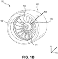
- Gas turbine engine 120 may comprise a nacelle 101, fan section 122, and nose cone 102.
- Fan section 122 may comprise a plurality of circumferentially arranged fan blades 121.
- Fan platforms 123, or spacers, may be arranged between adjacent fan blades 121.
- Fan blades 121 may be mounted to a fan hub 103 located radially inward of fan platforms 123.
- Nose cone 102 may be arranged forward of fan blades 121 to provide an aerodynamic flow path through fan section 122 along with fan platforms 123.
- a foreign object debris (FOD) detection system 265 may be configured to track FOD that has entered the inlet of a gas turbine engine.
- FOD detection system 265 may be used to detect an elevation, azimuth and duration of FOD that has entered the inlet by scanning a pre-determined volume forward of fan blades 121.
- the present disclosure may improve FOD detection, and accuracy of FOD size and trajectory during operation of gas turbine engine 120, allowing for more accurate maintenance and/or inspection schedules of engine blades.
- the present disclosure may make reference to FOD detection systems forward of fan blades 121, it should be understood by one skilled in the art that the present disclosure extends to any potential FOD detection systems within gas turbine engine 120, and/or any other suitable engine.
- FOD detection system 265 may comprise various components to aid in FOD detection and/or tracking.
- FOD detection system 265 may comprise a light detection and ranging (LiDAR) sensor assembly 270 and/or a FOD detection processor 290.
- FOD detection system 265 may be installed within nacelle 101 of gas turbine engine 120, as discussed further herein. In that respect, FOD detection system 265 may be coupled to nacelle 101 and may allow for FOD detection and/or tracking during operation of gas turbine engine 120. In various embodiments, FOD detection system 265 may also be removably inserted within nacelle 101.
- LiDAR light detection and ranging
- FOD detection system 265 may comprise FOD detection processor 290.
- FOD detection processor 290 may be in electronic communication with LiDAR sensor assembly 270.
- FOD detection processor 290 may be integrated into computer systems onboard an aircraft, such as, for example, a full authority digital engine control (FADEC), an engine-indicating and crew-alerting system (EICAS), and/or the like.
- FOD detection processor 290 may include one or more processors and/or one or more tangible, non-transitory memories and be capable of implementing logic.
- Each processor can be a general purpose processor, a digital signal processor (DSP), an application specific integrated circuit (ASIC), a field programmable gate array (FPGA) or other programmable logic device, discrete gate or transistor logic, discrete hardware components, or any combination thereof.
- DSP digital signal processor
- ASIC application specific integrated circuit
- FPGA field programmable gate array
- FOD detection processor 290 may comprise a processor configured to implement various logical operations in response to execution of instructions, for example, instructions stored on a non-transitory, tangible, computer-readable medium.
- non-transitory is to be understood to remove only propagating transitory signals per se from the claim scope and does not relinquish rights to all standard computer-readable media that are not only propagating transitory signals per se.
- non-transitory computer-readable medium and “non-transitory computer-readable storage medium” should be construed to exclude only those types of transitory computer-readable media which were found in In Re Nuijten to fall outside the scope of patentable subject matter under 35 U.S.C. ⁇ 101.
- FOD detection processor 290 may be configured to control FOD detection system 265.
- FOD detection processor 290 may be configured to transfer a control signal to increase a resolution in a local area of a tracking zone in response to detecting FOD in the local area.
- FOD detection processor 290 may generate and transmit the control signal based on an input received from the LiDAR sensor assembly 270.
- the excitation control signal may comprise electronic instructions configured to cause the LiDAR sensor assembly 270 to pulse and/or scan a pre-determined volume in an inlet of the gas-turbine engine, as discussed further herein.
- the scan may be configured to concentrate on a local volume in response to detection of FOD.
- the LiDAR sensor assembly 270 may be configured to sear a beam to various azimuths and elevations, send and receive a returned pulse at each azimuth and elevation (i.e., each grid point).
- the scan may be achieved via mechanical means, solid state means, or the like.
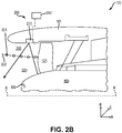
- LiDAR sensor assembly 270 is configured to scan a pre-determined volume 320 within an inlet 310 of a gas turbine engine 120.
- the inlet 310 may be at least partially defined by nacelle 101, nose cone 102 and fan blades 121.
- the LiDAR sensor assembly 270 may comprise a transceiver, a transmitter and receiver, or the like.
- the LiDAR sensor assembly 270 may be configured to rapidly transmit light. The light may be transmitted in various directions and define a pre-determined volume 320 in inlet 310.
- the light transmitted from the LiDAR sensor assembly 270 may reflect off a component in the inlet (e.g., the nose cone 102) and return to the LiDAR sensor assembly 270.
- the LiDAR sensor assembly 270 may be configured to receive the returned light via a transceiver, a receiver, or the like.
- the LiDAR sensor assembly 270 may be configured to measure the time it takes for the emitted light to travel to the component in the inlet 310 and back. The time may be used to calculate a distance via LiDAR sensor assembly 270.
- the LiDAR sensor may define a spatial relation of components in the inlet 310 during normal operation of gas turbine engine 120. In doing so, LiDAR sensor may be configured to identify, detect, and/or track FOD 301 that enters inlet 310 along an FOD path 302.
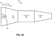
- FOD detection system 465 may comprise the LiDAR sensor assembly 270 and FOD detection processor 290.
- Gas turbine engine 400 comprises an inlet 410, an engine core 420, and an exhaust 430.
- the inlet comprises a centerbody 412 disposed at a forward end of inlet 410.
- LiDAR sensor assembly 270 may be coupled to the centerbody 412 of inlet 410 (e.g., a bifurcated inlet) and directed in the aft direction towards engine core 420.
- the LiDAR sensor assembly 270 may be configured to scan a volume aft of centerbody 412. By mounting the LiDAR sensor assembly 270 to centerbody 412, the LiDAR sensor assembly 270 may scan an entire volume of or substantially an entire volume of inlet 410 prior to entering engine core 420.
- LiDAR sensor assembly 270 is configured to scan a pre-determined volume 415 within an inlet 410 of a gas turbine engine 400.
- the LiDAR sensor assembly 270 may comprise a transceiver, a transmitter and receiver, or the like.
- the LiDAR sensor assembly 270 may be configured to rapidly transmit light. The light may be transmitted in various directions and define a pre-determined volume 415 in inlet 410.
- the light transmitted from the LiDAR sensor assembly 270 may reflect off an inner surface of inlet 410 and/or fan section 422 of engine core 420 and return to the LiDAR sensor assembly 270.
- the LiDAR sensor assembly 270 may be configured to receive the returned light via a transceiver, a receiver, or the like.
- the LiDAR sensor assembly 270 may be configured to measure the time it takes for the emitted light to travel to the inner surface of inlet 410 and/or the fan section 422 and back. The time may be used to calculate a distance via LiDAR sensor assembly 270.
- the LiDAR sensor assembly 270 may define a spatial relation of inlet 410 in the pre-determined volume 415 during normal operation of gas turbine engine 400. In doing so, LiDAR sensor assembly 270 may be configured to identify, detect, and/or track FOD 401 that enters inlet 410 along a FOD path 402 and travels through the pre-determined volume 415. The LiDAR sensor assembly 270 may be configured to target a local area within pre-determined volume 415 of inlet 410 when LiDAR sensor detects FOD 401. In doing so, LiDAR sensor may more accurately map and/or track FOD 401 as it travels along FOD path 402 and enters engine core 420.
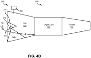
- FOD detection system 565 may comprise LiDAR sensor assembly 270 and FOD detection processor 290.
- Gas turbine engine 500 comprises an inlet 510, an engine core 520, and an exhaust 530.
- the inlet comprises a centerbody 512 disposed at a forward end of inlet 510.
- LiDAR sensor assembly 270 may be coupled to the centerbody 512 of inlet 510 and directed RADIALLY outward towards an inner surface of inlet 510.
- the LiDAR sensor assembly 270 may be configured to scan a volume radially outward of centerbody 412.
- LiDAR sensor may be configured to rotate about centerbody 512. By mounting the LiDAR sensor assembly 270 to centerbody 412, LiDAR sensor may scan an entire pre-determined volume 515 in inlet 510 prior to entering engine core 420 and/or ensure any FOD traveling through the inlet 510 is detected.
- LiDAR sensor assembly 270 is configured to scan a pre-determined volume 515 within an inlet 310 of a gas turbine engine 500.
- the LiDAR sensor assembly 270 may comprise a transceiver, a transmitter and receiver, or the like.
- the LiDAR sensor assembly 270 may be configured to rapidly transmit light. The light may be transmitted in various directions and define a pre-determined volume 515 in inlet 510. The light transmitted from the LiDAR sensor assembly 270 may reflect off an inner surface of inlet 510 and return to the LiDAR sensor assembly 270.
- the LiDAR sensor assembly 270 may be configured to receive the returned light via a transceiver, a receiver, or the like.
- the LiDAR sensor assembly 270 may be configured to measure the time it takes for the emitted light to travel to the inner surface of inlet 410 and/or the fan section 422 and back. The time may be used to calculate a distance via LiDAR sensor assembly 270.
- the LiDAR sensor may define a spatial relation of inlet 510 in the pre-determined volume 515 during normal operation of gas turbine engine 400.
- LiDAR sensor assembly 270 may be configured to identify, detect, and/or track FOD 501 that enters inlet 510 along a FOD path 502 and travels through the pre-determined volume 515.
- the LiDAR sensor assembly 270 may be configured to target a local area within pre-determined volume 515 of inlet 510 when LiDAR sensor detects FOD 501. In doing so, LiDAR sensor may more accurately map and/or track FOD 501 as it travels along FOD path 502 and enters engine core 520.
- a gas turbine engine may comprise a plurality of LiDAR assemblies.
- the LiDAR sensor assemblies from FIGs. 2A-4B may be used in any combination and be within the scope of this disclosure. As such, using a plurality of LiDAR sensor assemblies may allow tracking of FOD from entering the inlet until the FOD reaches the engine core.
- a LiDAR sensor assembly 270 may be disposed anywhere in inlet 410 and be within the scope of this disclosure. The LiDAR sensor assembly 270 may be configured to track any FOD that enters an inlet of a gas turbine engine as disclosed herein.
- LiDAR sensor assembly 670 comprises a plurality of transceivers 672.
- the plurality of transceivers 672 may be arranged in an array. Each transceiver in the plurality of transceivers 672 may be aimed in a different direction.
- the plurality of transceivers 672 may be arranged to define a pre-determined volume to be scanned.
- Each transceiver may be configured to output a pulsed beam.
- the angle and/or width of each pulsed beam in the plurality of pulsed beams 674 may be defined by a resolution of the respective pulsed beam.
- each pulsed beam in the plurality of pulsed beams 674 may have the same resolution.
- a corresponding FOD detection processor in a respective FOD detection system may increase a resolution of a first portion of beams in the plurality of pulsed beams 674 and decrease a resolution of a second portion of beams in the plurality of pulsed beams 674 in response to detecting FOD proximate the first portion of beams.
- the enhanced resolution of the pulsed beams directed proximate the FOD may more accurately track the FOD as it travels towards an engine core.
- each transceiver in the plurality of transceivers 672 are fixed. Each transceiver may scan its respective direction at the same time as an adjacent transceiver, or each transceiver may scan its respective direction sequentially following an adjacent transceiver.
- LiDAR sensor assembly 270 in FIGs. 2A-4B may be in accordance with LiDAR sensor assembly 670.
- LiDAR sensor assembly 770 comprises a plurality of transmitters 772 and a receiver 780.
- the plurality of transmitters 772 may be arranged in an array. Each transmitter in the plurality of transmitters 772 may be aimed in a different direction.
- the plurality of transmitters 772 may be arranged to define a pre-determined volume to be scanned.
- Each transmitter may be configured to output a pulsed beam.
- the angle and/or width of each pulsed beam in the plurality of pulsed beams 774 may be defined by a resolution of the respective pulsed beam.
- each pulsed beam in the plurality of pulsed beams 774 may have the same resolution.
- a corresponding FOD detection processor in a respective FOD detection system may increase a resolution of a first portion of beams in the plurality of pulsed beams 774 and decrease a resolution of a second portion of beams in the plurality of pulsed beams 774 in response to detecting FOD proximate the first portion of beams.
- the enhanced resolution of the pulsed beams directed proximate the FOD may more accurately track the FOD as it travels towards an engine core.
- each transmitter in the plurality of transmitters 772 are fixed. Each transmitter may scan its respective direction sequentially following an adjacent transceiver. By scanning each transmitter in the plurality of transmitters 772 sequentially, the receiver can correlate the return beam to a respective transmitter in the plurality of transmitters 772.
- LiDAR sensor assembly 270 in FIGs. 2A-4B may be in accordance with LiDAR sensor assembly 770.
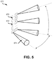
- LiDAR sensor assembly 870 comprises a plurality of receivers 880 and a transmitter 872.
- the plurality of receivers 880 may be arranged in an array. Each receiver in the plurality of receivers 880 may be aimed in a different direction.
- the plurality of receivers 880 may be arranged to cover and/or define a pre-determined volume to be scanned.
- the transmitter 872 may be configured to output a non-directional pulsed beam 874.
- the angle and/or width of the pulsed beam may be defined by a resolution of the respective pulsed beam and configured to provide a return to each receiver in the plurality of receivers 880.
- each receiver in the plurality of receivers 880 and the transmitter 872 are fixed.
- the transmitter 872 may scan the volume illuminated by the non-directional pulsed beam.
- Each receiver in the plurality of receivers 880 may be aligned in a pre-defined direction.
- a scan of the volume of non-directional pulsed beam 874 may be achieved after each pulse.
- LiDAR sensor assembly 270 in FIGs. 2A-4B may be in accordance with LiDAR sensor assembly 870.
- LiDAR sensor assembly 270 in FIGS. 2A-4B may comprise a single transceiver configured to scan a respective predefined volume by scanning in various directions.
- the various directions of the transceiver may create a grid in the respective predefined volume and detect FOD by determining any changes to the spatial relationships in the predefined volume.
- the method comprises detecting foreign object debris (FOD) (step 902).
- the FOD may be detected by a plurality of transmitters or a plurality of transceivers from a LiDAR sensor assembly.
- the FOD may first be detected by a respective transmitter or transceiver in the plurality of transmitters or the plurality of transceivers.
- a resolution of a first portion of transmitters or transceivers that are adjacent to the respective transmitter or receiver may be increased (step 904).
- the method 900 may further comprise decreasing a resolution of a second portion of transmitters or transceivers (step 906).
- the second portion of transmitters or transceivers are mutually exclusive from the first portion of transmitters or receivers.
- the method 900 may further comprise tracking the FOD via the first portion of transmitters or transceivers (step 908). By increasing the resolution of the transmitters or transceivers that reflect off the FOD, the path of the FOD may more accurately be detected, while maintaining the amount of power consumption of the FOD detection system.
Landscapes
- Engineering & Computer Science (AREA)
- Physics & Mathematics (AREA)
- Chemical & Material Sciences (AREA)
- Combustion & Propulsion (AREA)
- Mechanical Engineering (AREA)
- General Engineering & Computer Science (AREA)
- General Physics & Mathematics (AREA)
- Electromagnetism (AREA)
- Computer Networks & Wireless Communication (AREA)
- Radar, Positioning & Navigation (AREA)
- Remote Sensing (AREA)
- Life Sciences & Earth Sciences (AREA)
- General Life Sciences & Earth Sciences (AREA)
- Geophysics (AREA)
- Optical Radar Systems And Details Thereof (AREA)
- Testing Of Engines (AREA)
Applications Claiming Priority (1)
| Application Number | Priority Date | Filing Date | Title |
|---|---|---|---|
| US16/714,262 US11840933B2 (en) | 2019-12-13 | 2019-12-13 | LiDAR based FOD detection for gas-turbine engines |
Publications (2)
| Publication Number | Publication Date |
|---|---|
| EP3835560A1 true EP3835560A1 (fr) | 2021-06-16 |
| EP3835560B1 EP3835560B1 (fr) | 2023-05-10 |
Family
ID=73789817
Family Applications (1)
| Application Number | Title | Priority Date | Filing Date |
|---|---|---|---|
| EP20212584.5A Active EP3835560B1 (fr) | 2019-12-13 | 2020-12-08 | Détection de débris d'objets étrangers (fod) basée sur lidar pour moteurs à turbine à gaz |
Country Status (2)
| Country | Link |
|---|---|
| US (1) | US11840933B2 (fr) |
| EP (1) | EP3835560B1 (fr) |
Families Citing this family (1)
| Publication number | Priority date | Publication date | Assignee | Title |
|---|---|---|---|---|
| US12146416B2 (en) * | 2023-04-18 | 2024-11-19 | Rtx Corporation | Propulsor blade imaging assembly for an aircraft propulsion system |
Citations (4)
| Publication number | Priority date | Publication date | Assignee | Title |
|---|---|---|---|---|
| US20100003121A1 (en) * | 2006-10-12 | 2010-01-07 | Berryann Andrew P | Variable area fan nozzle for accommodating a foreign object strike event |
| US20160216142A1 (en) * | 2014-05-13 | 2016-07-28 | The Boeing Company | Methods and apparatus to determine airflow conditions at an inlet of an engine |
| US9909971B2 (en) * | 2013-09-06 | 2018-03-06 | Ge Aviation Systems Llc | Aircraft and particulate detection method |
| US20180298778A1 (en) * | 2017-04-18 | 2018-10-18 | Honeywell International Inc. | Gas turbine engine particulate ingestion and accumulation sensor system and method |
Family Cites Families (6)
| Publication number | Priority date | Publication date | Assignee | Title |
|---|---|---|---|---|
| GB2532585B (en) | 2013-06-30 | 2018-04-25 | Wind Farm Analytics Ltd | Turbine fluid velocity field measurement |
| GB201407313D0 (en) * | 2014-04-25 | 2014-06-11 | Rolls Royce Plc | Intake liner |
| US9776731B1 (en) | 2016-09-29 | 2017-10-03 | The Boeing Company | Methods and apparatus for detecting aircraft surface deformations |
| US11513198B2 (en) * | 2019-01-04 | 2022-11-29 | Waymo Llc | LIDAR pulse elongation |
| US10759543B1 (en) * | 2019-04-17 | 2020-09-01 | Raytheon Technologies Corporation | Detection system for gas turbine engine |
| US20210163141A1 (en) * | 2019-11-28 | 2021-06-03 | Pratt & Whitney Canada Corp. | Gas turbine engine, nacelle thereof, and associated method of operating a gas turbine engine |
-
2019
- 2019-12-13 US US16/714,262 patent/US11840933B2/en active Active
-
2020
- 2020-12-08 EP EP20212584.5A patent/EP3835560B1/fr active Active
Patent Citations (4)
| Publication number | Priority date | Publication date | Assignee | Title |
|---|---|---|---|---|
| US20100003121A1 (en) * | 2006-10-12 | 2010-01-07 | Berryann Andrew P | Variable area fan nozzle for accommodating a foreign object strike event |
| US9909971B2 (en) * | 2013-09-06 | 2018-03-06 | Ge Aviation Systems Llc | Aircraft and particulate detection method |
| US20160216142A1 (en) * | 2014-05-13 | 2016-07-28 | The Boeing Company | Methods and apparatus to determine airflow conditions at an inlet of an engine |
| US20180298778A1 (en) * | 2017-04-18 | 2018-10-18 | Honeywell International Inc. | Gas turbine engine particulate ingestion and accumulation sensor system and method |
Also Published As
| Publication number | Publication date |
|---|---|
| EP3835560B1 (fr) | 2023-05-10 |
| US11840933B2 (en) | 2023-12-12 |
| US20210180466A1 (en) | 2021-06-17 |
Similar Documents
| Publication | Publication Date | Title |
|---|---|---|
| EP3361229B1 (fr) | Système et procédé de surveillance de la santé de la pale de rotor | |
| US10196927B2 (en) | System and method for locating a probe within a gas turbine engine | |
| US11287353B2 (en) | Gearbox sensor arrangement | |
| US10822997B2 (en) | Inspection tool and method | |
| EP2870346B1 (fr) | Identification de mode de pale à mesure de synchronisation de pointe avancée | |
| US11346239B2 (en) | Heat flux measurement system | |
| AU751226B2 (en) | Device and method for actively reducing the noise emissions of jet engines and for diagnosing the same | |
| US9869249B2 (en) | Speed sensor probe location in gas turbine engine | |
| US20210017870A1 (en) | Curvic Seal for Gas Turbine Engine | |
| EP3071940B1 (fr) | Surveillance d'un paramètre dynamique tel qu'un couple dans un système rotatif | |
| US11732599B2 (en) | Methods and apparatus for real-time clearance assessment using a pressure measurement | |
| EP3835560B1 (fr) | Détection de débris d'objets étrangers (fod) basée sur lidar pour moteurs à turbine à gaz | |
| US10196922B2 (en) | System and method for locating a probe within a gas turbine engine | |
| US10690475B2 (en) | Encapsulated fan cap probe | |
| EP3726026A1 (fr) | Système de détection pour moteur à turbine à gaz | |
| US12487124B2 (en) | Systems and methods for measuring temperature | |
| US9228448B2 (en) | Background radiation measurement system | |
| US20160003093A1 (en) | Fan Axial Containment System | |
| US20140093362A1 (en) | Gas turbine engine components and method of assembly | |
| US20140147263A1 (en) | Turbine vane with mistake reduction feature | |
| EP2971675B1 (fr) | Positionnement d'une sonde de capteur de vitesse dans un moteur à turbine à gaz | |
| US20250020557A1 (en) | In situ engine airfoil process compensated resonance testing | |
| US20140219793A1 (en) | Health monitoring for hollow blades | |
| CN120322609A (zh) | 具有用于检测风扇的轴向位移的装置的飞行器涡轮发动机 |
Legal Events
| Date | Code | Title | Description |
|---|---|---|---|
| PUAI | Public reference made under article 153(3) epc to a published international application that has entered the european phase |
Free format text: ORIGINAL CODE: 0009012 |
|
| STAA | Information on the status of an ep patent application or granted ep patent |
Free format text: STATUS: THE APPLICATION HAS BEEN PUBLISHED |
|
| AK | Designated contracting states |
Kind code of ref document: A1 Designated state(s): AL AT BE BG CH CY CZ DE DK EE ES FI FR GB GR HR HU IE IS IT LI LT LU LV MC MK MT NL NO PL PT RO RS SE SI SK SM TR |
|
| STAA | Information on the status of an ep patent application or granted ep patent |
Free format text: STATUS: REQUEST FOR EXAMINATION WAS MADE |
|
| 17P | Request for examination filed |
Effective date: 20210816 |
|
| RBV | Designated contracting states (corrected) |
Designated state(s): AL AT BE BG CH CY CZ DE DK EE ES FI FR GB GR HR HU IE IS IT LI LT LU LV MC MK MT NL NO PL PT RO RS SE SI SK SM TR |
|
| GRAP | Despatch of communication of intention to grant a patent |
Free format text: ORIGINAL CODE: EPIDOSNIGR1 |
|
| STAA | Information on the status of an ep patent application or granted ep patent |
Free format text: STATUS: GRANT OF PATENT IS INTENDED |
|
| INTG | Intention to grant announced |
Effective date: 20221223 |
|
| GRAS | Grant fee paid |
Free format text: ORIGINAL CODE: EPIDOSNIGR3 |
|
| GRAA | (expected) grant |
Free format text: ORIGINAL CODE: 0009210 |
|
| STAA | Information on the status of an ep patent application or granted ep patent |
Free format text: STATUS: THE PATENT HAS BEEN GRANTED |
|
| AK | Designated contracting states |
Kind code of ref document: B1 Designated state(s): AL AT BE BG CH CY CZ DE DK EE ES FI FR GB GR HR HU IE IS IT LI LT LU LV MC MK MT NL NO PL PT RO RS SE SI SK SM TR |
|
| REG | Reference to a national code |
Ref country code: GB Ref legal event code: FG4D |
|
| REG | Reference to a national code |
Ref country code: AT Ref legal event code: REF Ref document number: 1566883 Country of ref document: AT Kind code of ref document: T Effective date: 20230515 Ref country code: CH Ref legal event code: EP |
|
| REG | Reference to a national code |
Ref country code: DE Ref legal event code: R096 Ref document number: 602020010709 Country of ref document: DE |
|
| REG | Reference to a national code |
Ref country code: IE Ref legal event code: FG4D |
|
| P01 | Opt-out of the competence of the unified patent court (upc) registered |
Effective date: 20230603 |
|
| REG | Reference to a national code |
Ref country code: LT Ref legal event code: MG9D |
|
| REG | Reference to a national code |
Ref country code: NL Ref legal event code: MP Effective date: 20230510 |
|
| REG | Reference to a national code |
Ref country code: AT Ref legal event code: MK05 Ref document number: 1566883 Country of ref document: AT Kind code of ref document: T Effective date: 20230510 |
|
| PG25 | Lapsed in a contracting state [announced via postgrant information from national office to epo] |
Ref country code: SE Free format text: LAPSE BECAUSE OF FAILURE TO SUBMIT A TRANSLATION OF THE DESCRIPTION OR TO PAY THE FEE WITHIN THE PRESCRIBED TIME-LIMIT Effective date: 20230510 Ref country code: PT Free format text: LAPSE BECAUSE OF FAILURE TO SUBMIT A TRANSLATION OF THE DESCRIPTION OR TO PAY THE FEE WITHIN THE PRESCRIBED TIME-LIMIT Effective date: 20230911 Ref country code: NO Free format text: LAPSE BECAUSE OF FAILURE TO SUBMIT A TRANSLATION OF THE DESCRIPTION OR TO PAY THE FEE WITHIN THE PRESCRIBED TIME-LIMIT Effective date: 20230810 Ref country code: NL Free format text: LAPSE BECAUSE OF FAILURE TO SUBMIT A TRANSLATION OF THE DESCRIPTION OR TO PAY THE FEE WITHIN THE PRESCRIBED TIME-LIMIT Effective date: 20230510 Ref country code: ES Free format text: LAPSE BECAUSE OF FAILURE TO SUBMIT A TRANSLATION OF THE DESCRIPTION OR TO PAY THE FEE WITHIN THE PRESCRIBED TIME-LIMIT Effective date: 20230510 Ref country code: AT Free format text: LAPSE BECAUSE OF FAILURE TO SUBMIT A TRANSLATION OF THE DESCRIPTION OR TO PAY THE FEE WITHIN THE PRESCRIBED TIME-LIMIT Effective date: 20230510 |
|
| RAP4 | Party data changed (patent owner data changed or rights of a patent transferred) |
Owner name: RTX CORPORATION |
|
| PG25 | Lapsed in a contracting state [announced via postgrant information from national office to epo] |
Ref country code: RS Free format text: LAPSE BECAUSE OF FAILURE TO SUBMIT A TRANSLATION OF THE DESCRIPTION OR TO PAY THE FEE WITHIN THE PRESCRIBED TIME-LIMIT Effective date: 20230510 Ref country code: PL Free format text: LAPSE BECAUSE OF FAILURE TO SUBMIT A TRANSLATION OF THE DESCRIPTION OR TO PAY THE FEE WITHIN THE PRESCRIBED TIME-LIMIT Effective date: 20230510 Ref country code: LV Free format text: LAPSE BECAUSE OF FAILURE TO SUBMIT A TRANSLATION OF THE DESCRIPTION OR TO PAY THE FEE WITHIN THE PRESCRIBED TIME-LIMIT Effective date: 20230510 Ref country code: LT Free format text: LAPSE BECAUSE OF FAILURE TO SUBMIT A TRANSLATION OF THE DESCRIPTION OR TO PAY THE FEE WITHIN THE PRESCRIBED TIME-LIMIT Effective date: 20230510 Ref country code: IS Free format text: LAPSE BECAUSE OF FAILURE TO SUBMIT A TRANSLATION OF THE DESCRIPTION OR TO PAY THE FEE WITHIN THE PRESCRIBED TIME-LIMIT Effective date: 20230910 Ref country code: HR Free format text: LAPSE BECAUSE OF FAILURE TO SUBMIT A TRANSLATION OF THE DESCRIPTION OR TO PAY THE FEE WITHIN THE PRESCRIBED TIME-LIMIT Effective date: 20230510 Ref country code: GR Free format text: LAPSE BECAUSE OF FAILURE TO SUBMIT A TRANSLATION OF THE DESCRIPTION OR TO PAY THE FEE WITHIN THE PRESCRIBED TIME-LIMIT Effective date: 20230811 |
|
| PG25 | Lapsed in a contracting state [announced via postgrant information from national office to epo] |
Ref country code: FI Free format text: LAPSE BECAUSE OF FAILURE TO SUBMIT A TRANSLATION OF THE DESCRIPTION OR TO PAY THE FEE WITHIN THE PRESCRIBED TIME-LIMIT Effective date: 20230510 |
|
| PG25 | Lapsed in a contracting state [announced via postgrant information from national office to epo] |
Ref country code: SK Free format text: LAPSE BECAUSE OF FAILURE TO SUBMIT A TRANSLATION OF THE DESCRIPTION OR TO PAY THE FEE WITHIN THE PRESCRIBED TIME-LIMIT Effective date: 20230510 |
|
| PG25 | Lapsed in a contracting state [announced via postgrant information from national office to epo] |
Ref country code: SM Free format text: LAPSE BECAUSE OF FAILURE TO SUBMIT A TRANSLATION OF THE DESCRIPTION OR TO PAY THE FEE WITHIN THE PRESCRIBED TIME-LIMIT Effective date: 20230510 Ref country code: SK Free format text: LAPSE BECAUSE OF FAILURE TO SUBMIT A TRANSLATION OF THE DESCRIPTION OR TO PAY THE FEE WITHIN THE PRESCRIBED TIME-LIMIT Effective date: 20230510 Ref country code: RO Free format text: LAPSE BECAUSE OF FAILURE TO SUBMIT A TRANSLATION OF THE DESCRIPTION OR TO PAY THE FEE WITHIN THE PRESCRIBED TIME-LIMIT Effective date: 20230510 Ref country code: EE Free format text: LAPSE BECAUSE OF FAILURE TO SUBMIT A TRANSLATION OF THE DESCRIPTION OR TO PAY THE FEE WITHIN THE PRESCRIBED TIME-LIMIT Effective date: 20230510 Ref country code: DK Free format text: LAPSE BECAUSE OF FAILURE TO SUBMIT A TRANSLATION OF THE DESCRIPTION OR TO PAY THE FEE WITHIN THE PRESCRIBED TIME-LIMIT Effective date: 20230510 Ref country code: CZ Free format text: LAPSE BECAUSE OF FAILURE TO SUBMIT A TRANSLATION OF THE DESCRIPTION OR TO PAY THE FEE WITHIN THE PRESCRIBED TIME-LIMIT Effective date: 20230510 |
|
| REG | Reference to a national code |
Ref country code: DE Ref legal event code: R097 Ref document number: 602020010709 Country of ref document: DE |
|
| PLBE | No opposition filed within time limit |
Free format text: ORIGINAL CODE: 0009261 |
|
| STAA | Information on the status of an ep patent application or granted ep patent |
Free format text: STATUS: NO OPPOSITION FILED WITHIN TIME LIMIT |
|
| 26N | No opposition filed |
Effective date: 20240213 |
|
| PG25 | Lapsed in a contracting state [announced via postgrant information from national office to epo] |
Ref country code: SI Free format text: LAPSE BECAUSE OF FAILURE TO SUBMIT A TRANSLATION OF THE DESCRIPTION OR TO PAY THE FEE WITHIN THE PRESCRIBED TIME-LIMIT Effective date: 20230510 |
|
| PG25 | Lapsed in a contracting state [announced via postgrant information from national office to epo] |
Ref country code: SI Free format text: LAPSE BECAUSE OF FAILURE TO SUBMIT A TRANSLATION OF THE DESCRIPTION OR TO PAY THE FEE WITHIN THE PRESCRIBED TIME-LIMIT Effective date: 20230510 Ref country code: IT Free format text: LAPSE BECAUSE OF FAILURE TO SUBMIT A TRANSLATION OF THE DESCRIPTION OR TO PAY THE FEE WITHIN THE PRESCRIBED TIME-LIMIT Effective date: 20230510 |
|
| REG | Reference to a national code |
Ref country code: CH Ref legal event code: PL |
|
| PG25 | Lapsed in a contracting state [announced via postgrant information from national office to epo] |
Ref country code: LU Free format text: LAPSE BECAUSE OF NON-PAYMENT OF DUE FEES Effective date: 20231208 |
|
| PG25 | Lapsed in a contracting state [announced via postgrant information from national office to epo] |
Ref country code: MC Free format text: LAPSE BECAUSE OF FAILURE TO SUBMIT A TRANSLATION OF THE DESCRIPTION OR TO PAY THE FEE WITHIN THE PRESCRIBED TIME-LIMIT Effective date: 20230510 |
|
| REG | Reference to a national code |
Ref country code: BE Ref legal event code: MM Effective date: 20231231 |
|
| PG25 | Lapsed in a contracting state [announced via postgrant information from national office to epo] |
Ref country code: MC Free format text: LAPSE BECAUSE OF FAILURE TO SUBMIT A TRANSLATION OF THE DESCRIPTION OR TO PAY THE FEE WITHIN THE PRESCRIBED TIME-LIMIT Effective date: 20230510 Ref country code: LU Free format text: LAPSE BECAUSE OF NON-PAYMENT OF DUE FEES Effective date: 20231208 |
|
| REG | Reference to a national code |
Ref country code: IE Ref legal event code: MM4A |
|
| PG25 | Lapsed in a contracting state [announced via postgrant information from national office to epo] |
Ref country code: IE Free format text: LAPSE BECAUSE OF NON-PAYMENT OF DUE FEES Effective date: 20231208 |
|
| PG25 | Lapsed in a contracting state [announced via postgrant information from national office to epo] |
Ref country code: BE Free format text: LAPSE BECAUSE OF NON-PAYMENT OF DUE FEES Effective date: 20231231 |
|
| PG25 | Lapsed in a contracting state [announced via postgrant information from national office to epo] |
Ref country code: CH Free format text: LAPSE BECAUSE OF NON-PAYMENT OF DUE FEES Effective date: 20231231 |
|
| PG25 | Lapsed in a contracting state [announced via postgrant information from national office to epo] |
Ref country code: IE Free format text: LAPSE BECAUSE OF NON-PAYMENT OF DUE FEES Effective date: 20231208 Ref country code: CH Free format text: LAPSE BECAUSE OF NON-PAYMENT OF DUE FEES Effective date: 20231231 Ref country code: BE Free format text: LAPSE BECAUSE OF NON-PAYMENT OF DUE FEES Effective date: 20231231 |
|
| PG25 | Lapsed in a contracting state [announced via postgrant information from national office to epo] |
Ref country code: BG Free format text: LAPSE BECAUSE OF FAILURE TO SUBMIT A TRANSLATION OF THE DESCRIPTION OR TO PAY THE FEE WITHIN THE PRESCRIBED TIME-LIMIT Effective date: 20230510 |
|
| PG25 | Lapsed in a contracting state [announced via postgrant information from national office to epo] |
Ref country code: BG Free format text: LAPSE BECAUSE OF FAILURE TO SUBMIT A TRANSLATION OF THE DESCRIPTION OR TO PAY THE FEE WITHIN THE PRESCRIBED TIME-LIMIT Effective date: 20230510 |
|
| PG25 | Lapsed in a contracting state [announced via postgrant information from national office to epo] |
Ref country code: CY Free format text: LAPSE BECAUSE OF FAILURE TO SUBMIT A TRANSLATION OF THE DESCRIPTION OR TO PAY THE FEE WITHIN THE PRESCRIBED TIME-LIMIT; INVALID AB INITIO Effective date: 20201208 |
|
| PG25 | Lapsed in a contracting state [announced via postgrant information from national office to epo] |
Ref country code: HU Free format text: LAPSE BECAUSE OF FAILURE TO SUBMIT A TRANSLATION OF THE DESCRIPTION OR TO PAY THE FEE WITHIN THE PRESCRIBED TIME-LIMIT; INVALID AB INITIO Effective date: 20201208 |
|
| REG | Reference to a national code |
Ref country code: DE Ref legal event code: R081 Ref document number: 602020010709 Country of ref document: DE Owner name: RTX CORPORATION (N.D.GES.D. STAATES DELAWARE),, US Free format text: FORMER OWNER: RAYTHEON TECHNOLOGIES CORPORATION, FARMINGTON, CT, US |
|
| PG25 | Lapsed in a contracting state [announced via postgrant information from national office to epo] |
Ref country code: TR Free format text: LAPSE BECAUSE OF FAILURE TO SUBMIT A TRANSLATION OF THE DESCRIPTION OR TO PAY THE FEE WITHIN THE PRESCRIBED TIME-LIMIT Effective date: 20230510 |
|
| PGFP | Annual fee paid to national office [announced via postgrant information from national office to epo] |
Ref country code: DE Payment date: 20251126 Year of fee payment: 6 |
|
| PGFP | Annual fee paid to national office [announced via postgrant information from national office to epo] |
Ref country code: GB Payment date: 20251120 Year of fee payment: 6 |
|
| PGFP | Annual fee paid to national office [announced via postgrant information from national office to epo] |
Ref country code: FR Payment date: 20251120 Year of fee payment: 6 |