EP3835568B1 - Système de torche - Google Patents
Système de torche Download PDFInfo
- Publication number
- EP3835568B1 EP3835568B1 EP19214662.9A EP19214662A EP3835568B1 EP 3835568 B1 EP3835568 B1 EP 3835568B1 EP 19214662 A EP19214662 A EP 19214662A EP 3835568 B1 EP3835568 B1 EP 3835568B1
- Authority
- EP
- European Patent Office
- Prior art keywords
- flare
- air
- gas
- unit
- energy
- Prior art date
- Legal status (The legal status is an assumption and is not a legal conclusion. Google has not performed a legal analysis and makes no representation as to the accuracy of the status listed.)
- Active
Links
Images



Classifications
-
- F—MECHANICAL ENGINEERING; LIGHTING; HEATING; WEAPONS; BLASTING
- F02—COMBUSTION ENGINES; HOT-GAS OR COMBUSTION-PRODUCT ENGINE PLANTS
- F02G—HOT GAS OR COMBUSTION-PRODUCT POSITIVE-DISPLACEMENT ENGINE PLANTS; USE OF WASTE HEAT OF COMBUSTION ENGINES; NOT OTHERWISE PROVIDED FOR
- F02G1/00—Hot gas positive-displacement engine plants
- F02G1/04—Hot gas positive-displacement engine plants of closed-cycle type
- F02G1/043—Hot gas positive-displacement engine plants of closed-cycle type the engine being operated by expansion and contraction of a mass of working gas which is heated and cooled in one of a plurality of constantly communicating expansible chambers, e.g. Stirling cycle type engines
- F02G1/053—Component parts or details
-
- F—MECHANICAL ENGINEERING; LIGHTING; HEATING; WEAPONS; BLASTING
- F02—COMBUSTION ENGINES; HOT-GAS OR COMBUSTION-PRODUCT ENGINE PLANTS
- F02G—HOT GAS OR COMBUSTION-PRODUCT POSITIVE-DISPLACEMENT ENGINE PLANTS; USE OF WASTE HEAT OF COMBUSTION ENGINES; NOT OTHERWISE PROVIDED FOR
- F02G1/00—Hot gas positive-displacement engine plants
- F02G1/04—Hot gas positive-displacement engine plants of closed-cycle type
- F02G1/043—Hot gas positive-displacement engine plants of closed-cycle type the engine being operated by expansion and contraction of a mass of working gas which is heated and cooled in one of a plurality of constantly communicating expansible chambers, e.g. Stirling cycle type engines
- F02G1/053—Component parts or details
- F02G1/055—Heaters or coolers
-
- F—MECHANICAL ENGINEERING; LIGHTING; HEATING; WEAPONS; BLASTING
- F23—COMBUSTION APPARATUS; COMBUSTION PROCESSES
- F23G—CREMATION FURNACES; CONSUMING WASTE PRODUCTS BY COMBUSTION
- F23G5/00—Incineration of waste; Incinerator constructions; Details, accessories or control therefor
- F23G5/44—Details; Accessories
- F23G5/46—Recuperation of heat
-
- F—MECHANICAL ENGINEERING; LIGHTING; HEATING; WEAPONS; BLASTING
- F23—COMBUSTION APPARATUS; COMBUSTION PROCESSES
- F23G—CREMATION FURNACES; CONSUMING WASTE PRODUCTS BY COMBUSTION
- F23G7/00—Incinerators or other apparatus for consuming industrial waste, e.g. chemicals
- F23G7/06—Incinerators or other apparatus for consuming industrial waste, e.g. chemicals of waste gases or noxious gases, e.g. exhaust gases
- F23G7/08—Incinerators or other apparatus for consuming industrial waste, e.g. chemicals of waste gases or noxious gases, e.g. exhaust gases using flares, e.g. in stacks
- F23G7/085—Incinerators or other apparatus for consuming industrial waste, e.g. chemicals of waste gases or noxious gases, e.g. exhaust gases using flares, e.g. in stacks in stacks
-
- F—MECHANICAL ENGINEERING; LIGHTING; HEATING; WEAPONS; BLASTING
- F02—COMBUSTION ENGINES; HOT-GAS OR COMBUSTION-PRODUCT ENGINE PLANTS
- F02G—HOT GAS OR COMBUSTION-PRODUCT POSITIVE-DISPLACEMENT ENGINE PLANTS; USE OF WASTE HEAT OF COMBUSTION ENGINES; NOT OTHERWISE PROVIDED FOR
- F02G2254/00—Heat inputs
- F02G2254/10—Heat inputs by burners
-
- F—MECHANICAL ENGINEERING; LIGHTING; HEATING; WEAPONS; BLASTING
- F23—COMBUSTION APPARATUS; COMBUSTION PROCESSES
- F23G—CREMATION FURNACES; CONSUMING WASTE PRODUCTS BY COMBUSTION
- F23G2206/00—Waste heat recuperation
- F23G2206/20—Waste heat recuperation using the heat in association with another installation
- F23G2206/203—Waste heat recuperation using the heat in association with another installation with a power/heat generating installation
-
- Y—GENERAL TAGGING OF NEW TECHNOLOGICAL DEVELOPMENTS; GENERAL TAGGING OF CROSS-SECTIONAL TECHNOLOGIES SPANNING OVER SEVERAL SECTIONS OF THE IPC; TECHNICAL SUBJECTS COVERED BY FORMER USPC CROSS-REFERENCE ART COLLECTIONS [XRACs] AND DIGESTS
- Y02—TECHNOLOGIES OR APPLICATIONS FOR MITIGATION OR ADAPTATION AGAINST CLIMATE CHANGE
- Y02E—REDUCTION OF GREENHOUSE GAS [GHG] EMISSIONS, RELATED TO ENERGY GENERATION, TRANSMISSION OR DISTRIBUTION
- Y02E20/00—Combustion technologies with mitigation potential
- Y02E20/12—Heat utilisation in combustion or incineration of waste
Definitions
- the present invention relates to a flare system capable of recovering energy in residue gases generated in an industrial process, such as a smelting plant.
- residue gases are used to some extent in various heating applications in the smelting plant.
- typically a large portion (e.g. 40% or more) of the residue gas cannot be recovered and is then typically burned in a flare stack in order to get rid of the toxic CO.
- JP2009 156233 A1 , US 2006/213196 A1 and US 2019/101079 A1 disclose various systems for recovery of energy in a flow of residual gas generated in an industrial process.
- a flare stack is a cheap and robust way to combust residual gas with varying content, and to eliminate any explosive or poisonous gases included therein.
- a flare stack typically includes a relatively tall vertical pipe, to ensure that the flare is located at an elevated position to avoid high concentrated poisonous gases and heat radiation on ground also providing a small facility footprint.
- the combustion in a flare is performed at low (atmospheric) pressure, and is sufficiently safe to operate in areas of high safety regulations.
- the flare also has a highly dynamic burn rate, which may be easily controlled from zero to a large burn rate.
- a flare does have a few significant drawbacks. To begin with, it has no useful energy conversion, i.e. all energy content in the residue gas is consumed and evaporated into the surroundings. Further, the open flare causes noise and a potentially disturbing light. Finally, the flare may cause particle pollution in its near vicinity, as sufficient particle filtering is typically not provided before flaring or possible to implement at flare tip. Also CO2 capture is hard to implement at flare tip.
- FIG. 1 shows schematically an industrial site 1 where a turbine power station 4 is connected to a smelting plant 1.
- the permanent crew of personnel is housed in a building 5. Construction and installation of the turbine power station and building 5 would not be possible inside the perimeter of the site 1 without interrupting the smelting process for a considerable time, and the turbine station 4 and building 5 are therefore placed outside the site perimeter.
- the residue gas is led to the turbine in a long pipe 6.
- the whole turbine infrastructure requires detailed planning and advanced construction. It also requires highly trained personnel for both operation and maintenance.
- each plant producing residue gas has a unique characteristic of the gas flow in terms of content, median flow, minimum flow, maximum flow, flow variance over the production cycle.
- An energy conversion system with optimum profit must therefore be designed according to the local prerequisites which increase the cost and complexity of planning and construction. The increased cost and complexity lead to a negative return on investment, especially for smaller average residue gas power flows, e.g. 10 MW output power or less.
- a flare system for recovery of energy in a flow of residual gas generated in an industrial process, the system including a flare stack connected to the flow of residue gas and arranged to perform open combustion of the residue gas, and at least one modular flare unit connected to the flow of residue gas in parallel with the flare stack, the modular flare unit being arranged to recover energy in the residue gas.
- Each modular flare unit includes a frame, at least two energy conversion modules detachably supported by the frame, a fuel manifold connected to receive the flow of residue gas, an air manifold connected to receive air from the ambient, an exhaust manifold connected to receive exhaust from the energy conversion modules, and an electric generator.
- Each energy conversion module includes a combustion chamber having a fuel inlet selectively connectable to the fuel manifold via a fuel valve, an air inlet selectively connectable to the air manifold via an air valve, and an exhaust outlet connected to the exhaust manifold, the combustion chamber configured to receive a flow of residue gas through the fuel inlet for combustion in the chamber at near atmospheric pressure, and a Stirling engine configured to convert heat from the combustion chamber into mechanical energy, the Stirling engine having a heat engine heat exchanger including a set of tubes conducting a compressible working fluid, a portion of the heat engine heat exchanger extending into the combustion chamber, and one or several cylinders each having a piston connected to an output shaft.
- the electric generator is connected to the output shaft and is configured to generate electric power from the mechanical energy.
- the invention is based on the realization that combustion at, or close to, atmospheric pressure, avoids most drawbacks with an internal combustion engine, which conventionally have been used to recover energy from residue gas.
- a machine capable of converting heat energy from low pressure combustion is the Stirling engine.
- a Stirling engine is an external combustion engine, i.e. an engine which uses a heat carrying medium to convert heat from a low pressure combustion process into mechanical (rotational) energy.
- a heat exchanger of a Stirling engine including a set of tubes for carrying a working fluid, e.g. hydrogen gas, may therefore extend into a combustion chamber, where residue gas from an industrial plant is supplied and combusted.
- the combustion in such a Stirling engine is similar to that of a flare stack, i.e. combustion at (or close to) atmospheric pressure. As such, it may safely handle contaminated gas and varying levels of H2.
- a Stirling engine is a complex and expensive machine.
- Conventional Stirling engines are much too small to be relevant in the context of an industry process such as a smelting plant. And to design a significantly larger Stirling engine and arbitrary output power according to local prerequisites would be difficult and costly.
- a Stirling engine will inevitably require maintenance at some point which will be less efficient and more costly with many variants of engines.
- EP 18214336.2 discloses a system of several Stirling engines which may be used to recover energy in residue gases.
- a system of Stirling engines is used as a modular flare unit, arranged in parallel with a conventional flare stack.
- the result is a safe and efficient conversion of residue gas which may be installed quickly (i.e. during a scheduled interruption of production) and without substantial construction.
- it is simply a question of briefly interrupting the flow of gas to the flare stack in order to insert a flow valve which may direct a portion of the flow to one or several modular flare units.
- each module may be individually disconnected, removed from the system e.g. for repair or maintenance. During such repair or maintenance of a module, a replacement module may be connected. This is beneficial, as it does not require permanent presence of operating staff. Service and maintenance of each unit may be performed off-site, avoiding long process interruptions, as well as additional risks and cost of building a workshop in a hazardous environment. This in turn means that the flare unit may be placed on site, also in a hazardous environment, thus avoiding the need for long pipe transportation of residue gas.
- Each flare unit may have a preset number of energy conversion modules and thus a preset power.
- a flare unit may comprise 14 modules and have a total output power of around 400 kW.
- this threshold may for an example be at least 80% from an investment point of view alone besides environmental considerations.
- a modular flare unit comprising several Stirling engines (modules) may further be dynamically controlled to handle quickly varying flows of gas.
- one or several individual Stirling engines may be shut down instantaneously and without warning using the inlet valve.
- the capacity to absorb a gas flow will therefore be significant. A high degree of energy conversion from the fluctuating flow of residue gas may thus be achieved.
- a modular flare unit according to the invention may be used as the only power conversion system, but may alternatively be used in combination with a large scale power station like a turbine to extend the power conversion rate.
- an energy conversion system according to the invention is principally more similar to a flare process than to a turbine station. Not only does the combustion take place a low (atmospheric) pressure, but the capacity is also dynamically adjustable on short time frame under very safe conditions, similar to a flare and on long term by providing a flexible build system to according to local prerequisites in terms of gas flow as discussed above.
- a "standard built" modular flare unit according to the present invention is inexpensive, and may be motivated by a relatively small supply of residue gas. Consequently, it may be used to convert energy from the fluctuating flow of gas too small to power a turbine or equivalent power system.
- the flare stack may be an elevated flare (e.g. as shown in figure 1 ) or a ground flare (i.e. flaring closer to ground).
- An elevated stack has the advantage of emissions and radiation being located at a distance from personnel on the ground.
- a ground flare may on the other hand be less expensive to put in place.
- a ground flare may be enclosed by suitable walls.
- inventive concept is in fact not necessarily limited to include a flare stack at all.
- a flare system according to the present invention may only include the flare unit(s), and still provide the above mentioned advantages.
- each energy conversion module comprises an individual electrical generator. This further facilitates disconnection of one energy conversion module, as there all mechanical connections between the Stirling engine and the generator are contained in the module.
- Each energy conversion module is preferably a "standard" (one-size) module, i.e. all modules are manufactured to be identical in design and function. Such standardized modules will reduce manufacturing costs (economy of scale) and also reduce cost for installation, maintenance, spare parts, training, etc. Preferably, also each flare unit is standardized, to even further increase the economies of scale.
- the flare unit may be pre-built in a standardized intermodal container, thereby facilitating transport and installation.
- Embodiments of the present invention will now be described with reference to an industrial site 1 where a smelting plant 2 is operated.
- the smelting plant receives metal ore 3, and outputs different types of metal.
- As a bi-product of this process is a flow of residue gas, including a mix of gaseous compounds, including H2, CO, and also various particles. As it may contain toxic gases (such as CO), this gas must be handled carefully, and not be emitted into the ambient surroundings.
- the flare system according to the invention may be useful for residue gasses containing CO, H 2 and various C x H y gases. Residue gas of this kind are typically formed during production of Ferro-alloys.
- the flare system disclosed herein could be useful also for Combined Oxygen Gas (COG), Blast Furnace Gas (BFG) and Basic Oxygen Furnace Gas (BOFG).
- COG Combined Oxygen Gas
- BFG Blast Furnace Gas
- BOFG Basic Oxygen Furnace Gas
- Table 1 below (published in the article " Burners in the steel industry: utilization of by-product combustion gases in reheating furnaces and annealing lines", by Sebastian Caillat, Energy Procedia, Volume 120, August 2017, Pages 20-27 ) provides typical gas compositions for three different metal industry processes, Combined Oxygen Gas (COG), Blast Furnace Gas (BFG) and Basic Oxygen Furnace Gas (BOFG). Table 1. Typical gas composition and characteristics in steel mills [2], [5], [6], [8]. Element/Parameter Unit COG BFG BOFG H 2 % vol. 36.1-61.7 1- 8 2-10 CO % vol. 3.4-5.8 19- 27 55 -80 CH 4 % vol.
- COG Combined Oxygen Gas
- BFG Blast Furnace Gas
- BOFG Basic Oxygen Furnace Gas
- Some residual gasses may be reused to a high extent within the industrial process (e.g. smelting). Also BOFG and BFG is reused (drying) within the metal industry process, but there is significant a surplus that typically is burned in a flare stack.
- the site 1 in figure 1 therefore includes a flare stack 7, where the residue gas may be burned, thereby effectively getting rid of toxic gases like CO.
- the stack is provided with reside gas through pipe 8, channeling all gas which is not reused in the plant or otherwise recovered.
- an additional flare system 10 is connected in parallel with the flare stack 7, to a branch 9 of pipe 8.
- the additional flare system 10 is modular, and includes several standard built units 30 optimized to local gas supply (see figure 3 ), each unit including a several, preferably more than 10, energy conversion modules 40 with a Stirling engine (see figure 4 ).
- the number of modules 40 in each unit 30 may vary depending on design choice, but typically two rows of modules (an upper and a lower row) is suitable, leading to an even number of modules.
- a gas conditioning unit 11 is arranged along the pipe 9, and is configured to pre-condition the residue gas. The pre-conditioning may involve pre-heating the residue gas to a temperature suitable for combustion in the flare system 10. Further, the pre-conditioning unit 11 may include a filter, e.g. a "scrubber", to remove particles present in the residue gas.
- residue gas from the smelting plant may contain 50 mg/Nm 3 , which is preferably reduced to around 2.5 mg/Nm 3 by the scrubber. It may also be appropriate to dehumidify the residue gas, i.e. remove water vapor present in the gas. As an example, the humidity may be brought down to 80% or less.
- the conditioning unit may pressurize the gas to an extent that it is forced to the flare system 10.
- the flare system 10 may comprise one or several fans to create an under-pressure sucking the residue to the flare system 10.
- FIG. 3 shows one of the units 30 in more detail.
- each unit 11 includes fourteen energy conversion modules 40, each being releasably arranged in a frame 31, e.g. formed by a standard size intermodal cargo container.
- the frame 31 has a predefined number of bays 32, each which is configured to receive an energy conversion module 40.
- the bay is provided with a suitable mechanical fixation device, for securing the module 40 in the bay 32.
- each bay 32 may also be closed by a lid or hatch, to prevent access to the modules 40.
- Each energy conversion module 40 includes a Stirling engine 41 and one combustion chamber 42, as will be shown more clearly in figures 4a and 4b .
- each Stirling engine may have an output power of 30 kW, in which case the unit 30 (which here has 14 modules) has an output power of around 400 kW.
- the unit 30 (which here has 14 modules) has an output power of around 400 kW.
- FIG 1 there are six flare units 30, thus a total energy converting output power of around 2.4 MW.
- the modular flare system 10 has been adapted to the expected average flow of residual gas from this particular plant.
- the first three flare units (the lower three slices 21) will operate 24/7, as the energy content always exceeds 1.2 MW.
- the next two units will operate almost always, only briefly interrupted during periods 22 when the energy content of the residue gas is lower than average.
- the final unit (uppermost slice 21a) will operate at least 80% of the time (i.e. 80% utilization ratio), providing a maximum energy conversion capacity of 2.4 MW.
- the threshold for when an additional flare unit should be added to the system i.e.
- an intermediate gas storage 12 connected to the pipe 9, in order to allow for storage of surplus residue gas during periods when the gas energy content exceeds the capacity of the flare system 10.
- the intermediate storage 12 could be present within the industrial facility (as shown in figure 1 ) or could be built together with the flare system according to the local prerequisites. Intermediate storage may be specifically useful for quickly varying energy content, as illustrated in figure 2b .
- the gas flow has periodic energy peaks corresponding to the capacity of two flare units. Under such circumstances, it may not be possible to economically motivate an additional flare unit.
- by introducing an intermediate gas storage 12 it may be possible to operate an additional flare unit almost continuously (slice 21b in figure 2b ).
- Quickly variating gas flow requires smaller intermediate storage capacity compared to slow variations.
- the unit 30 is connected to the pipe 9 (see figure 1 ) and includes a manifold 33 which connects the flow of residue gas to each combustion chamber 42, where it can be combusted at near atmospheric pressure.
- the pressure in the combustion chamber 42 is slightly greater than atmospheric pressure, e.g. 0 - 500 mbar greater, preferably 50 -100 mbar greater.
- Each branch of the manifold 33 is provided with an ON/OFF valve 34, to enable disconnection of each module 40 from the flow of residue gas.
- a second manifold 35 is connected to provide air from the ambient to the modules 40.
- a fan 36 forces ambient air into the manifold 35.
- Each branch of this manifold 35 is also provided with some means to interrupt the flow, for example a valve 37.
- each module 40 may be provided with an individual fan for incoming air, in which case the flow of incoming air may be interrupted by turning off the fan.
- a third manifold 38 is connected to receive exhaust from the modules 40.
- a fan 39 is arranged to force the exhaust through the manifold 38.
- a filtering unit 50 may be arranged at the end of the exhaust manifold 38 to provide additional particle filtering and/or CO 2 capture of the exhaust gases. This may be especially advantageous if additional recovery of heat energy from the exhaust gases is intended. It is noted that the exhaust gases (even after cooling in the heat exchangers 44 and 45, see below) may contain significant amounts of heat energy, which may be recovered.
- manifolds 33, 35 and 38 are illustrated as arranged external to the frame 31, one or several of the manifolds may alternatively be arranged inside the frame.
- the fuel and air manifolds 33, 35 may be arranged inside the frame 31, while the exhaust manifold 38 is arranged outside the frame 31.
- the module 40 includes a Stirling engine 41, a low pressure combustion chamber 42, and a heat engine heat exchanger 43 extending into the chamber 42.
- the module further comprises an air heat exchanger 44 connected to the air supply valve 36.
- a fuel inlet 46 of the combustion chamber is connected to receive residual gas, while an air inlet 47 is connected to receive air from the air heat exchanger 44.
- An exhaust outlet 48 of the combustion chamber is connected to the air heat exchanger 44, where it pre-heats the incoming air.
- the residual gas may be conditioned and preheated in the conditioning unit 11.
- each module 40 may also include a fuel heat exchanger 45 configured to heat the incoming fuel (residual gas) using the exhausts. As shown in figure 4b , it may be connected downstream the air heat exchanger.
- the heat exchanger(s) the temperature of the combusted exhaust gases can be significantly reduced, and the energy conversion can be made even more efficient.
- air heat exchanger 44 and fuel heat exchanger 45 alternatively be shared by several (or all) energy conversion modules 40 in the unit 30.
- Each module 40 should, however, be provided with separate valves 34 and 36 in order to allow disconnection of the module 40.
- FIG 4b Also shown in figure 4b is an air filter 36a arranged before the valve 35 to remove particles from the incoming air.
- This filter 36a may be integrated in the fan 36, or may be individual for each module 40.
- the Stirling engine 41 is further connected to an output shaft (not shown in figure 4a and 4b ), and the module 40 is thus configured to convert chemical energy in the residue gas to mechanical (rotational) energy.
- the output shaft is in turn connected to an electrical generator 49 for generation of electrical energy.
- the generator may be connected to a local energy storage, to the local industry power grid, or be connected to supply power to the mains power grid.
- each module 40 includes a separate generator 49.
- two or more modules 40 are connected to a common generator.
- all modules 40 of a flare unit 30 may share one single generator.
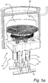
- Figure 5a shows some of the elements of the energy conversion module 40 in more detail.
- the combustion chamber 42 with the fuel inlet 46, and the heat engine heat exchanger 43 extending into the chamber 42.
- the Stirling engine 41 having one or several cylinders 51 each having a piston 52 connected to an output shaft 53 by means of a rod 54.
- a Stirling engine moves a working fluid (e.g. hydrogen gas) back and forth between a cold side and a warm side of a cylinder. On the warm side, the working fluid expands, thus operating the piston in the cylinder. On its path between the cold side and the warm side, the working fluid is heated.
- the working fluid pressure thus alternates between a high pressure (during the compression stage) and a low pressure (during the expansion stage).
- the pressure ratio may be 1 to 1.6.
- the heating of working fluid is accomplished by the heat engine heat exchanger 43, which comprises a set of tubes 43a extending into the combustion chamber. As fuel is burned in the combustion chamber, the working fluid in the heat exchanger is heated before reaching the warm side of the cylinder.
- the illustrated Stirling engine 41 comprises four cylinders 51, each associated with one section of the heat exchanger 43, as shown in figure 5b .
- each cylinder 51 and associated part of the heat exchanger 43 form a separate working fluid circuit 55.
- these fluid circuits are connected, such that each four-cylinder Stirling engine has only one single working fluid circuit 55.
- the valves 34 and 37 are closed, and the module is disconnected from all three manifolds 33, 35 and 38. Further, the generator 49 is disconnected from the power system to which it delivers electrical power. After that, the module 40 may be removed from the frame 31.
- the unit 30 may then be operated with one less module 40, or alternatively the module 40 is replaced by another module 40 before operation is resumed.
- the number of cylinders in each Stirling engine may be other than four.
- the number of energy conversion modules in each unit may be smaller than or greater than 14 (although it is preferably an even number for symmetry reasons). Most likely a unit (container) contains at least ten modules.
Landscapes
- Engineering & Computer Science (AREA)
- Mechanical Engineering (AREA)
- General Engineering & Computer Science (AREA)
- Environmental & Geological Engineering (AREA)
- Chemical & Material Sciences (AREA)
- Combustion & Propulsion (AREA)
- Engine Equipment That Uses Special Cycles (AREA)
Claims (15)
- Système de torche destiné à la récupération d'énergie dans un flux de gaz résiduel généré au cours d'un processus industriel, le système comprenant :une colonne de brûlage (7) reliée au flux de gaz résiduel et conçue pour réaliser une combustion ouverte dudit gaz résiduel, etau moins une unité de torche modulaire (10) reliée audit flux de gaz résiduel parallèlement à la colonne de brûlage, ladite unité de torche modulaire étant conçue pour la récupération d'énergie dans ledit gaz résiduel, chaque unité de torche modulaire (30) comprenant :un cadre (31) ;au moins deux modules de conversion d'énergie (40) supportés de façon détachable par le cadre ;un collecteur de combustible (33) raccordé de manière à recevoir le flux de gaz résiduel ;un collecteur d'air (35) raccordé de manière à recevoir de l'air à partir de l'environnement ;un collecteur d'échappement (38) raccordé de manière à recevoir l'échappement à partir des modules de conversion d'énergie (40) ; etun générateur électrique (49),chaque module de conversion d'énergie (40) comprenant :une chambre de combustion (42) comportant une entrée de combustible (46) apte à être reliée de façon sélective audit collecteur de combustible (33) par le biais d'une soupape à combustible (34), une entrée d'air (47) apte à être reliée de façon sélective audit collecteur d'air (35) par le biais d'une soupape à air (37), et une sortie d'échappement (48) reliée audit collecteur d'échappement (38), ladite chambre de combustion (42) étant configurée pour recevoir un flux de gaz résiduel à travers l'entrée de combustible (46) pour la combustion dans la chambre à un niveau de proche de la pression atmosphérique, etun moteur Stirling (41) configuré pour convertir de la chaleur provenant de la chambre de combustion (42) en énergie mécanique, ledit moteur Stirling (41) comportant un échangeur de chaleur de moteur thermique (43) comprenant un ensemble de tubes (43a) guidant un fluide de travail compressible, une partie dudit échangeur de chaleur de moteur thermique (43) s'étendant dans la chambre de combustion (42), et un ou plusieurs cylindres (51) comportant respectivement un piston (52) relié à un arbre de sortie (53),dans lequel ledit générateur électrique (49) est relié à l'arbre de sortie (53) et configuré pour générer une puissance électrique à partir de l'énergie mécanique.
- Système selon la revendication 1, dans lequel la colonne de brûlage est une colonne de brûlage élevée ou une colonne de brûlage au sol.
- Système selon la revendication 1 ou 2, dans lequel chaque module de conversion d'énergie (40) comprend un générateur électrique (49).
- Système selon l'une des revendications précédentes, dans lequel chaque module de conversion d'énergie (40) comprend en outre un échangeur de chaleur d'air (44) configuré pour préchauffer de l'air entrant à l'aide d'échappements provenant de ladite sortie d'échappement (48) et/ou un échangeur de chaleur de combustible (45) configuré pour préchauffer du combustible entrant à l'aide d'échappements provenant de ladite sortie d'échappement (48).
- Système selon l'une des revendications précédentes, comprenant en outre une unité de conditionnement de gaz (11) disposée en amont de l'unité de torche modulaire (30) .
- Système selon l'une des revendications précédentes, comprenant en outre une unité de stockage de gaz (12) disposée en amont de l'unité de torche modulaire (30).
- Système selon l'une des revendications précédentes, dans lequel l'unité de torche modulaire (30) comprend en outre au moins un filtre à air (36a) raccordé de manière à éliminer des particules dans l'air fourni à chaque entrée d'air (47).
- Système selon l'une des revendications précédentes, dans lequel chaque moteur Stirling (41) comporte une pluralité de cylindres (51), de préférence quatre.
- Système selon l'une quelconque des revendications précédentes, dans lequel chaque moteur Stirling (41) présente une capacité de puissance identique.
- Système selon l'une quelconque des revendications précédentes, dans lequel chaque module de conversion d'énergie (40) présente un design physique et fonctionnel substantiellement identique.
- Système selon l'une quelconque des revendications précédentes, comprenant en outre un ventilateur d'air (36) conçu pour forcer de l'air ambiant dans le collecteur d'air (35).
- Système selon l'une quelconque des revendications précédentes, comprenant en outre un ventilateur d'échappement (39) conçu pour forcer des échappements hors dudit collecteur d'échappement (38).
- Système selon l'une quelconque des revendications précédentes, comprenant en outre une unité de capture de CO2 (50) disposée sur le collecteur d'échappement (38) .
- Système selon l'une quelconque des revendications précédentes, dans lequel l'unité de torche modulaire (30) est logée dans un conteneur intermodal.
- Système selon l'une quelconque des revendications précédentes, dans lequel une pression dans chaque chambre de combustion est supérieure de 0 - 500 mbar à la pression atmosphérique, et de préférence supérieure de 50 - 100 mbar à la pression atmosphérique.
Priority Applications (7)
| Application Number | Priority Date | Filing Date | Title |
|---|---|---|---|
| PL19214662T PL3835568T3 (pl) | 2019-12-10 | 2019-12-10 | Układ pochodni |
| ES19214662T ES2909758T3 (es) | 2019-12-10 | 2019-12-10 | Sistema de antorcha |
| EP19214662.9A EP3835568B1 (fr) | 2019-12-10 | 2019-12-10 | Système de torche |
| CN202080086041.0A CN114930011B (zh) | 2019-12-10 | 2020-12-09 | 火炬系统 |
| US17/783,806 US11821386B2 (en) | 2019-12-10 | 2020-12-09 | Flare system |
| PCT/EP2020/085215 WO2021116151A1 (fr) | 2019-12-10 | 2020-12-09 | Système de torche |
| ZA2022/06313A ZA202206313B (en) | 2019-12-10 | 2022-06-07 | Flare system |
Applications Claiming Priority (1)
| Application Number | Priority Date | Filing Date | Title |
|---|---|---|---|
| EP19214662.9A EP3835568B1 (fr) | 2019-12-10 | 2019-12-10 | Système de torche |
Publications (2)
| Publication Number | Publication Date |
|---|---|
| EP3835568A1 EP3835568A1 (fr) | 2021-06-16 |
| EP3835568B1 true EP3835568B1 (fr) | 2021-12-29 |
Family
ID=68847950
Family Applications (1)
| Application Number | Title | Priority Date | Filing Date |
|---|---|---|---|
| EP19214662.9A Active EP3835568B1 (fr) | 2019-12-10 | 2019-12-10 | Système de torche |
Country Status (7)
| Country | Link |
|---|---|
| US (1) | US11821386B2 (fr) |
| EP (1) | EP3835568B1 (fr) |
| CN (1) | CN114930011B (fr) |
| ES (1) | ES2909758T3 (fr) |
| PL (1) | PL3835568T3 (fr) |
| WO (1) | WO2021116151A1 (fr) |
| ZA (1) | ZA202206313B (fr) |
Family Cites Families (12)
| Publication number | Priority date | Publication date | Assignee | Title |
|---|---|---|---|---|
| CN2457457Y (zh) * | 2000-12-19 | 2001-10-31 | 上海华力燃烧设备有限公司 | 地面火炬排放装置 |
| JP3513662B1 (ja) * | 2003-02-05 | 2004-03-31 | 鐵夫 杉岡 | コジェネレーションシステム |
| DK2079961T3 (da) * | 2006-11-08 | 2016-03-29 | Flare Ind Llc | Modulært afbrændingstårn og dets anvendelse til afbrænding af røggas |
| US8679291B2 (en) * | 2007-03-13 | 2014-03-25 | Heartland Technology Partners Llc | Compact wastewater concentrator using waste heat |
| JP4917011B2 (ja) * | 2007-12-27 | 2012-04-18 | 中部電力株式会社 | スターリングエンジン発電装置 |
| US9163564B2 (en) * | 2010-06-21 | 2015-10-20 | Chevron Phillips Chemical Company Lp | Method and system for energy generation in a chemical plant by utilizing flare gas |
| CN102434310A (zh) * | 2011-11-29 | 2012-05-02 | 南京航空航天大学 | 内燃机-斯特林机联合循环的混合动力系统 |
| US9337704B1 (en) * | 2015-11-20 | 2016-05-10 | Jerry Leslie | System for electricity generation by utilizing flared gas |
| IL248717B (en) | 2016-11-02 | 2021-05-31 | Sarine Tech Ltd | A system and method for detecting defects in a gemstone |
| WO2018119922A1 (fr) * | 2016-12-29 | 2018-07-05 | 深圳智慧能源技术有限公司 | Système de génération d'énergie à cycle combiné susceptible de récupérer l'énergie thermique de gaz résiduaire d'une turbine à gaz et d'une énergie froide de gnl |
| US10415501B2 (en) * | 2017-09-29 | 2019-09-17 | TriStar Technology, LLC | Method and apparatus for generating electricity utilizing heat from enclosed flares and other combustors |
| US11598284B2 (en) | 2018-12-20 | 2023-03-07 | Swedish Stirling Ab | Recovery of energy in residue gases |
-
2019
- 2019-12-10 EP EP19214662.9A patent/EP3835568B1/fr active Active
- 2019-12-10 ES ES19214662T patent/ES2909758T3/es active Active
- 2019-12-10 PL PL19214662T patent/PL3835568T3/pl unknown
-
2020
- 2020-12-09 CN CN202080086041.0A patent/CN114930011B/zh active Active
- 2020-12-09 WO PCT/EP2020/085215 patent/WO2021116151A1/fr not_active Ceased
- 2020-12-09 US US17/783,806 patent/US11821386B2/en active Active
-
2022
- 2022-06-07 ZA ZA2022/06313A patent/ZA202206313B/en unknown
Also Published As
| Publication number | Publication date |
|---|---|
| CN114930011B (zh) | 2023-12-22 |
| ZA202206313B (en) | 2023-03-29 |
| EP3835568A1 (fr) | 2021-06-16 |
| US20230036799A1 (en) | 2023-02-02 |
| PL3835568T3 (pl) | 2022-06-13 |
| WO2021116151A1 (fr) | 2021-06-17 |
| ES2909758T3 (es) | 2022-05-10 |
| CN114930011A (zh) | 2022-08-19 |
| US11821386B2 (en) | 2023-11-21 |
Similar Documents
| Publication | Publication Date | Title |
|---|---|---|
| TR201811281T4 (tr) | Plazma gazlaştırmayla hidrojen üretimine yönelik esnek modüler sistem. | |
| CN112195043A (zh) | 一种高炉煤气脱硫方法及装置 | |
| CN101099921B (zh) | 固废焚烧尾气处理方法及装置 | |
| EP3835568B1 (fr) | Système de torche | |
| CN110594755A (zh) | 一种基于纯氧燃烧的垃圾焚烧厂用飞灰熔融系统 | |
| CN110081445B (zh) | 一种液态危险废物焚烧系统及其焚烧工艺 | |
| CN201079730Y (zh) | 布袋除尘反应器 | |
| CN218763418U (zh) | 一种应急垃圾焚烧装置 | |
| CN217714876U (zh) | 一种蒸汽回收系统 | |
| CN214370242U (zh) | 一种含硫含盐废气废液洁净处理系统 | |
| CN216320864U (zh) | 废旧冰箱破碎分离过程的废气处理系统 | |
| CN217015752U (zh) | 煅烧烟气脱硫、脱硝、除尘一体化处理系统 | |
| CN213492933U (zh) | 一种再利用烧结球团废气中co的装置 | |
| CN210656798U (zh) | 固体有机危险废弃物低温热解处理系统 | |
| CN202303405U (zh) | 一种新型卧式焚烧炉 | |
| CN209926893U (zh) | 车底式焙烧炉节能减排系统 | |
| CN114395420A (zh) | 一种危险废物焚烧热解的等离子气化系统及方法 | |
| RU70962U1 (ru) | Установка для переработки твердых бытовых отходов | |
| CN219756384U (zh) | 一种尾气回收利用系统 | |
| CN223636182U (zh) | 一种化工制药废气收集协同减污降碳的净化处理系统 | |
| Komori et al. | CO2 emission reduction method through various gas turbine fuels applications | |
| CN224175147U (zh) | 一种冶金微粉制备的燃烧产物循环回收装置 | |
| CN216825626U (zh) | 一种燃原油锅炉设备的脱硫脱氮装置 | |
| CN220397566U (zh) | 一种工业硅余热深度回收利用及环保处理一体化系统 | |
| CN214345605U (zh) | 一种用于高浓度废气的安全处理装置 |
Legal Events
| Date | Code | Title | Description |
|---|---|---|---|
| PUAI | Public reference made under article 153(3) epc to a published international application that has entered the european phase |
Free format text: ORIGINAL CODE: 0009012 |
|
| STAA | Information on the status of an ep patent application or granted ep patent |
Free format text: STATUS: THE APPLICATION HAS BEEN PUBLISHED |
|
| AK | Designated contracting states |
Kind code of ref document: A1 Designated state(s): AL AT BE BG CH CY CZ DE DK EE ES FI FR GB GR HR HU IE IS IT LI LT LU LV MC MK MT NL NO PL PT RO RS SE SI SK SM TR |
|
| STAA | Information on the status of an ep patent application or granted ep patent |
Free format text: STATUS: REQUEST FOR EXAMINATION WAS MADE |
|
| 17P | Request for examination filed |
Effective date: 20210701 |
|
| RBV | Designated contracting states (corrected) |
Designated state(s): AL AT BE BG CH CY CZ DE DK EE ES FI FR GB GR HR HU IE IS IT LI LT LU LV MC MK MT NL NO PL PT RO RS SE SI SK SM TR |
|
| GRAP | Despatch of communication of intention to grant a patent |
Free format text: ORIGINAL CODE: EPIDOSNIGR1 |
|
| STAA | Information on the status of an ep patent application or granted ep patent |
Free format text: STATUS: GRANT OF PATENT IS INTENDED |
|
| INTG | Intention to grant announced |
Effective date: 20210917 |
|
| GRAS | Grant fee paid |
Free format text: ORIGINAL CODE: EPIDOSNIGR3 |
|
| GRAA | (expected) grant |
Free format text: ORIGINAL CODE: 0009210 |
|
| STAA | Information on the status of an ep patent application or granted ep patent |
Free format text: STATUS: THE PATENT HAS BEEN GRANTED |
|
| AK | Designated contracting states |
Kind code of ref document: B1 Designated state(s): AL AT BE BG CH CY CZ DE DK EE ES FI FR GB GR HR HU IE IS IT LI LT LU LV MC MK MT NL NO PL PT RO RS SE SI SK SM TR |
|
| REG | Reference to a national code |
Ref country code: GB Ref legal event code: FG4D |
|
| REG | Reference to a national code |
Ref country code: CH Ref legal event code: EP |
|
| REG | Reference to a national code |
Ref country code: AT Ref legal event code: REF Ref document number: 1458858 Country of ref document: AT Kind code of ref document: T Effective date: 20220115 |
|
| REG | Reference to a national code |
Ref country code: IE Ref legal event code: FG4D |
|
| REG | Reference to a national code |
Ref country code: DE Ref legal event code: R096 Ref document number: 602019010459 Country of ref document: DE |
|
| REG | Reference to a national code |
Ref country code: NO Ref legal event code: T2 Effective date: 20211229 |
|
| REG | Reference to a national code |
Ref country code: LT Ref legal event code: MG9D |
|
| REG | Reference to a national code |
Ref country code: SE Ref legal event code: TRGR |
|
| PG25 | Lapsed in a contracting state [announced via postgrant information from national office to epo] |
Ref country code: RS Free format text: LAPSE BECAUSE OF FAILURE TO SUBMIT A TRANSLATION OF THE DESCRIPTION OR TO PAY THE FEE WITHIN THE PRESCRIBED TIME-LIMIT Effective date: 20211229 Ref country code: LT Free format text: LAPSE BECAUSE OF FAILURE TO SUBMIT A TRANSLATION OF THE DESCRIPTION OR TO PAY THE FEE WITHIN THE PRESCRIBED TIME-LIMIT Effective date: 20211229 Ref country code: FI Free format text: LAPSE BECAUSE OF FAILURE TO SUBMIT A TRANSLATION OF THE DESCRIPTION OR TO PAY THE FEE WITHIN THE PRESCRIBED TIME-LIMIT Effective date: 20211229 Ref country code: BG Free format text: LAPSE BECAUSE OF FAILURE TO SUBMIT A TRANSLATION OF THE DESCRIPTION OR TO PAY THE FEE WITHIN THE PRESCRIBED TIME-LIMIT Effective date: 20220329 |
|
| REG | Reference to a national code |
Ref country code: NL Ref legal event code: MP Effective date: 20211229 |
|
| REG | Reference to a national code |
Ref country code: ES Ref legal event code: FG2A Ref document number: 2909758 Country of ref document: ES Kind code of ref document: T3 Effective date: 20220510 |
|
| REG | Reference to a national code |
Ref country code: AT Ref legal event code: MK05 Ref document number: 1458858 Country of ref document: AT Kind code of ref document: T Effective date: 20211229 |
|
| PG25 | Lapsed in a contracting state [announced via postgrant information from national office to epo] |
Ref country code: LV Free format text: LAPSE BECAUSE OF FAILURE TO SUBMIT A TRANSLATION OF THE DESCRIPTION OR TO PAY THE FEE WITHIN THE PRESCRIBED TIME-LIMIT Effective date: 20211229 Ref country code: HR Free format text: LAPSE BECAUSE OF FAILURE TO SUBMIT A TRANSLATION OF THE DESCRIPTION OR TO PAY THE FEE WITHIN THE PRESCRIBED TIME-LIMIT Effective date: 20211229 Ref country code: GR Free format text: LAPSE BECAUSE OF FAILURE TO SUBMIT A TRANSLATION OF THE DESCRIPTION OR TO PAY THE FEE WITHIN THE PRESCRIBED TIME-LIMIT Effective date: 20220330 |
|
| PG25 | Lapsed in a contracting state [announced via postgrant information from national office to epo] |
Ref country code: NL Free format text: LAPSE BECAUSE OF FAILURE TO SUBMIT A TRANSLATION OF THE DESCRIPTION OR TO PAY THE FEE WITHIN THE PRESCRIBED TIME-LIMIT Effective date: 20211229 |
|
| PG25 | Lapsed in a contracting state [announced via postgrant information from national office to epo] |
Ref country code: SM Free format text: LAPSE BECAUSE OF FAILURE TO SUBMIT A TRANSLATION OF THE DESCRIPTION OR TO PAY THE FEE WITHIN THE PRESCRIBED TIME-LIMIT Effective date: 20211229 Ref country code: SK Free format text: LAPSE BECAUSE OF FAILURE TO SUBMIT A TRANSLATION OF THE DESCRIPTION OR TO PAY THE FEE WITHIN THE PRESCRIBED TIME-LIMIT Effective date: 20211229 Ref country code: RO Free format text: LAPSE BECAUSE OF FAILURE TO SUBMIT A TRANSLATION OF THE DESCRIPTION OR TO PAY THE FEE WITHIN THE PRESCRIBED TIME-LIMIT Effective date: 20211229 Ref country code: PT Free format text: LAPSE BECAUSE OF FAILURE TO SUBMIT A TRANSLATION OF THE DESCRIPTION OR TO PAY THE FEE WITHIN THE PRESCRIBED TIME-LIMIT Effective date: 20220429 Ref country code: EE Free format text: LAPSE BECAUSE OF FAILURE TO SUBMIT A TRANSLATION OF THE DESCRIPTION OR TO PAY THE FEE WITHIN THE PRESCRIBED TIME-LIMIT Effective date: 20211229 Ref country code: CZ Free format text: LAPSE BECAUSE OF FAILURE TO SUBMIT A TRANSLATION OF THE DESCRIPTION OR TO PAY THE FEE WITHIN THE PRESCRIBED TIME-LIMIT Effective date: 20211229 |
|
| PG25 | Lapsed in a contracting state [announced via postgrant information from national office to epo] |
Ref country code: AT Free format text: LAPSE BECAUSE OF FAILURE TO SUBMIT A TRANSLATION OF THE DESCRIPTION OR TO PAY THE FEE WITHIN THE PRESCRIBED TIME-LIMIT Effective date: 20211229 |
|
| PG25 | Lapsed in a contracting state [announced via postgrant information from national office to epo] |
Ref country code: IS Free format text: LAPSE BECAUSE OF FAILURE TO SUBMIT A TRANSLATION OF THE DESCRIPTION OR TO PAY THE FEE WITHIN THE PRESCRIBED TIME-LIMIT Effective date: 20220429 |
|
| REG | Reference to a national code |
Ref country code: DE Ref legal event code: R097 Ref document number: 602019010459 Country of ref document: DE |
|
| PG25 | Lapsed in a contracting state [announced via postgrant information from national office to epo] |
Ref country code: DK Free format text: LAPSE BECAUSE OF FAILURE TO SUBMIT A TRANSLATION OF THE DESCRIPTION OR TO PAY THE FEE WITHIN THE PRESCRIBED TIME-LIMIT Effective date: 20211229 Ref country code: AL Free format text: LAPSE BECAUSE OF FAILURE TO SUBMIT A TRANSLATION OF THE DESCRIPTION OR TO PAY THE FEE WITHIN THE PRESCRIBED TIME-LIMIT Effective date: 20211229 |
|
| PLBE | No opposition filed within time limit |
Free format text: ORIGINAL CODE: 0009261 |
|
| STAA | Information on the status of an ep patent application or granted ep patent |
Free format text: STATUS: NO OPPOSITION FILED WITHIN TIME LIMIT |
|
| 26N | No opposition filed |
Effective date: 20220930 |
|
| P01 | Opt-out of the competence of the unified patent court (upc) registered |
Effective date: 20230421 |
|
| REG | Reference to a national code |
Ref country code: CH Ref legal event code: PL |
|
| REG | Reference to a national code |
Ref country code: BE Ref legal event code: MM Effective date: 20221231 |
|
| PG25 | Lapsed in a contracting state [announced via postgrant information from national office to epo] |
Ref country code: LU Free format text: LAPSE BECAUSE OF NON-PAYMENT OF DUE FEES Effective date: 20221210 |
|
| PG25 | Lapsed in a contracting state [announced via postgrant information from national office to epo] |
Ref country code: LI Free format text: LAPSE BECAUSE OF NON-PAYMENT OF DUE FEES Effective date: 20221231 Ref country code: IE Free format text: LAPSE BECAUSE OF NON-PAYMENT OF DUE FEES Effective date: 20221210 Ref country code: CH Free format text: LAPSE BECAUSE OF NON-PAYMENT OF DUE FEES Effective date: 20221231 |
|
| REG | Reference to a national code |
Ref country code: NO Ref legal event code: CREP Representative=s name: ZACCO NORWAY AS, POSTBOKS 488, 0213 OSLO, NORGE Ref country code: NO Ref legal event code: CHAD Owner name: TEXEL TECHNOLOGIES AB, SE |
|
| PG25 | Lapsed in a contracting state [announced via postgrant information from national office to epo] |
Ref country code: BE Free format text: LAPSE BECAUSE OF NON-PAYMENT OF DUE FEES Effective date: 20221231 |
|
| REG | Reference to a national code |
Ref country code: DE Ref legal event code: R081 Ref document number: 602019010459 Country of ref document: DE Owner name: TEXEL TECHNOLOGIES AB, SE Free format text: FORMER OWNER: SWEDISH STIRLING AB, VAESTRA FROELUNDA, SE |
|
| PG25 | Lapsed in a contracting state [announced via postgrant information from national office to epo] |
Ref country code: CY Free format text: LAPSE BECAUSE OF FAILURE TO SUBMIT A TRANSLATION OF THE DESCRIPTION OR TO PAY THE FEE WITHIN THE PRESCRIBED TIME-LIMIT Effective date: 20211229 |
|
| PG25 | Lapsed in a contracting state [announced via postgrant information from national office to epo] |
Ref country code: MK Free format text: LAPSE BECAUSE OF FAILURE TO SUBMIT A TRANSLATION OF THE DESCRIPTION OR TO PAY THE FEE WITHIN THE PRESCRIBED TIME-LIMIT Effective date: 20211229 Ref country code: HU Free format text: LAPSE BECAUSE OF FAILURE TO SUBMIT A TRANSLATION OF THE DESCRIPTION OR TO PAY THE FEE WITHIN THE PRESCRIBED TIME-LIMIT; INVALID AB INITIO Effective date: 20191210 |
|
| PG25 | Lapsed in a contracting state [announced via postgrant information from national office to epo] |
Ref country code: MC Free format text: LAPSE BECAUSE OF FAILURE TO SUBMIT A TRANSLATION OF THE DESCRIPTION OR TO PAY THE FEE WITHIN THE PRESCRIBED TIME-LIMIT Effective date: 20211229 |
|
| PG25 | Lapsed in a contracting state [announced via postgrant information from national office to epo] |
Ref country code: MC Free format text: LAPSE BECAUSE OF FAILURE TO SUBMIT A TRANSLATION OF THE DESCRIPTION OR TO PAY THE FEE WITHIN THE PRESCRIBED TIME-LIMIT Effective date: 20211229 |
|
| GBPC | Gb: european patent ceased through non-payment of renewal fee |
Effective date: 20231210 |
|
| PG25 | Lapsed in a contracting state [announced via postgrant information from national office to epo] |
Ref country code: MT Free format text: LAPSE BECAUSE OF FAILURE TO SUBMIT A TRANSLATION OF THE DESCRIPTION OR TO PAY THE FEE WITHIN THE PRESCRIBED TIME-LIMIT Effective date: 20211229 |
|
| PG25 | Lapsed in a contracting state [announced via postgrant information from national office to epo] |
Ref country code: GB Free format text: LAPSE BECAUSE OF NON-PAYMENT OF DUE FEES Effective date: 20231210 |
|
| PG25 | Lapsed in a contracting state [announced via postgrant information from national office to epo] |
Ref country code: GB Free format text: LAPSE BECAUSE OF NON-PAYMENT OF DUE FEES Effective date: 20231210 |
|
| REG | Reference to a national code |
Ref country code: ES Ref legal event code: PC2A Owner name: TEXEL TECHNOLOGIES AB Effective date: 20241204 |
|
| REG | Reference to a national code |
Ref country code: DE Ref legal event code: R082 Ref document number: 602019010459 Country of ref document: DE |
|
| PG25 | Lapsed in a contracting state [announced via postgrant information from national office to epo] |
Ref country code: TR Free format text: LAPSE BECAUSE OF FAILURE TO SUBMIT A TRANSLATION OF THE DESCRIPTION OR TO PAY THE FEE WITHIN THE PRESCRIBED TIME-LIMIT Effective date: 20211229 |
|
| PGFP | Annual fee paid to national office [announced via postgrant information from national office to epo] |
Ref country code: DE Payment date: 20251118 Year of fee payment: 7 |
|
| PGFP | Annual fee paid to national office [announced via postgrant information from national office to epo] |
Ref country code: NO Payment date: 20251118 Year of fee payment: 7 |
|
| PGFP | Annual fee paid to national office [announced via postgrant information from national office to epo] |
Ref country code: IT Payment date: 20251120 Year of fee payment: 7 |
|
| PGFP | Annual fee paid to national office [announced via postgrant information from national office to epo] |
Ref country code: FR Payment date: 20251017 Year of fee payment: 7 |
|
| PGFP | Annual fee paid to national office [announced via postgrant information from national office to epo] |
Ref country code: SE Payment date: 20251016 Year of fee payment: 7 |
|
| PGFP | Annual fee paid to national office [announced via postgrant information from national office to epo] |
Ref country code: PL Payment date: 20251021 Year of fee payment: 7 |
|
| PG25 | Lapsed in a contracting state [announced via postgrant information from national office to epo] |
Ref country code: SI Free format text: LAPSE BECAUSE OF FAILURE TO SUBMIT A TRANSLATION OF THE DESCRIPTION OR TO PAY THE FEE WITHIN THE PRESCRIBED TIME-LIMIT Effective date: 20211229 |
|
| PGFP | Annual fee paid to national office [announced via postgrant information from national office to epo] |
Ref country code: ES Payment date: 20260225 Year of fee payment: 7 |