EP3835569A1 - Zündvorrichtung für raketenmotor - Google Patents
Zündvorrichtung für raketenmotor Download PDFInfo
- Publication number
- EP3835569A1 EP3835569A1 EP20213227.0A EP20213227A EP3835569A1 EP 3835569 A1 EP3835569 A1 EP 3835569A1 EP 20213227 A EP20213227 A EP 20213227A EP 3835569 A1 EP3835569 A1 EP 3835569A1
- Authority
- EP
- European Patent Office
- Prior art keywords
- gas
- combustion chamber
- ignition device
- pressurized gas
- valve
- Prior art date
- Legal status (The legal status is an assumption and is not a legal conclusion. Google has not performed a legal analysis and makes no representation as to the accuracy of the status listed.)
- Granted
Links
Images
Classifications
-
- F—MECHANICAL ENGINEERING; LIGHTING; HEATING; WEAPONS; BLASTING
- F02—COMBUSTION ENGINES; HOT-GAS OR COMBUSTION-PRODUCT ENGINE PLANTS
- F02K—JET-PROPULSION PLANTS
- F02K9/00—Rocket-engine plants, i.e. plants carrying both fuel and oxidant therefor; Control thereof
- F02K9/95—Rocket-engine plants, i.e. plants carrying both fuel and oxidant therefor; Control thereof characterised by starting or ignition means or arrangements
-
- F—MECHANICAL ENGINEERING; LIGHTING; HEATING; WEAPONS; BLASTING
- F05—INDEXING SCHEMES RELATING TO ENGINES OR PUMPS IN VARIOUS SUBCLASSES OF CLASSES F01-F04
- F05D—INDEXING SCHEME FOR ASPECTS RELATING TO NON-POSITIVE-DISPLACEMENT MACHINES OR ENGINES, GAS-TURBINES OR JET-PROPULSION PLANTS
- F05D2260/00—Function
- F05D2260/99—Ignition, e.g. ignition by warming up of fuel or oxidizer in a resonant acoustic cavity
-
- F—MECHANICAL ENGINEERING; LIGHTING; HEATING; WEAPONS; BLASTING
- F05—INDEXING SCHEMES RELATING TO ENGINES OR PUMPS IN VARIOUS SUBCLASSES OF CLASSES F01-F04
- F05D—INDEXING SCHEME FOR ASPECTS RELATING TO NON-POSITIVE-DISPLACEMENT MACHINES OR ENGINES, GAS-TURBINES OR JET-PROPULSION PLANTS
- F05D2270/00—Control
- F05D2270/40—Type of control system
- F05D2270/42—Type of control system passive or reactive, e.g. using large wind vanes
Definitions
- the present invention relates to a passive ignition device suitable for an engine, in particular a rocket engine, and to a rocket propulsion assembly comprising a rocket engine and such an ignition device.
- a rocket is propelled by a propulsion unit generally comprising a motor called a rocket motor, intended to generate the exhaust gases necessary for the propulsion of the rocket and at least one propellant tank intended to supply the engine with oxidizer / fuel.
- Supply systems allow the propellants to be conveyed from the tanks to the rocket motor.
- a rocket engine generally includes a combustion chamber in which the exhaust gases are generated. These exhaust gases are then evacuated at very high speed out of the combustion chamber, most often via a divergent or a nozzle and produce a thrust making it possible to propel the rocket.
- the exhaust gases result from an encounter and combustion of propellants in the combustion chamber of the engine.
- space igniters are devices allowing to create energy at the origin of the start of combustion.
- the initiation of combustion by means of these space igniters consists, for example, in the creation of a spark produced by means of electric candles, in the creation of a hot surface produced by means of a glow plug, by the creation of a flame produced by a pyrotechnic explosion or by the creation of a plasma created locally by means of a laser beam.
- the object of the invention is in particular to alleviate at least one of these drawbacks and, according to a first aspect, relates to a passive ignition device suitable for an engine, in particular a rocket engine, the ignition device comprising a fuel tank. gas designed to contain a pressurized gas, a delivery circuit connected to the gas tank and configured to deliver the pressurized gas from the tank to a combustion chamber of the engine, and a rupture element arranged at the outlet of the tank and configured to rupture under the effect of pressure applied by the pressurized gas when the pressurized gas is supplied to the combustion chamber of the engine.
- the ignition device is configured to ignite an engine, in particular a rocket motor.
- passive a device devoid of initiators such as candles / lasers or other energy supply devices.
- the ignition device is thus simplified and additional recurring costs are eliminated.
- the device comprises a valve arranged between the reservoir and the rupture element, the valve being configured to be moved between a closed position in which the valve prevents circulation of the pressurized gas between the reservoir and the combustion chamber of so that no pressure is applied to the rupture element, and an open position in which the valve allows the circulation of pressurized gas to the combustion chamber when the igniter is connected to the combustion chamber so that the pressurized gas exerts pressure on the rupture element.
- the device comprises a non-return valve arranged between the reservoir and the rupture element, the valve being configured to prevent a return of the pressurized gas into the reservoir.
- the valve being configured to prevent a return of the pressurized gas into the reservoir.
- the device comprises an injector arranged at the outlet of the rupture element, the injector being configured to apply stresses to the pressurized gas before it enters the combustion chamber.
- the device comprises an inlet and filling valve connected to the reservoir and configured to regulate filling of the reservoir with pressurized gas.
- the rupture element is a calibrated membrane.
- the rupture element is a calibrated rupture disc.
- the reservoir contains gaseous hydrogen.
- the properties of hydrogen allow the ignition device to initiate the ignition of a combustion chamber by only means of gaseous hydrogen which propagates in the combustion chamber comprising the oxidant or the oxidant / reducing mixture. .
- the use of hydrogen allows the ignition device to dispense with the reagents used in the prior art such as hypergolic reagents which are generally toxic.
- this makes it possible to simplify the ignition device compared to devices of the art. that require additional reservoirs to hold reagents such as hypergolic reagents.
- this makes it easier to obtain the specific motor impulse, which is superior to hypergolic motors.
- the gaseous hydrogen is pressurized to at least 50 bar.
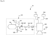
- FIG. 1 is a schematic representation of a passive ignition device according to one embodiment of the invention.
- the figure 1 illustrates a propulsion assembly 10 of a rocket (not shown) comprising a passive ignition device 100 according to one embodiment of the invention.
- the propulsion unit 10 is intended to propel the rocket.
- the propulsion unit 10 comprises a motor 200 called a rocket motor.
- the rocket engine 200 comprises a combustion chamber 205 in which exhaust gases are generated and a nozzle 210 through which the generated exhaust gases are discharged at high speed so as to produce a thrust allowing the propulsion of the rocket.
- the propulsion unit 10 comprises a first 310 and a second 320 propellant reservoir intended to supply the combustion chamber with propellant.
- the first tank 310 comprises a fuel (reducing agent) and the second tank 320 comprises an oxidizer (oxidant).
- the fuel and the oxidizer are conveyed to the combustion chamber 205 by means of circulation conduits 315, 325.
- the propellants (oxidizer and fuel) injected into the combustion chamber 205 are mixed and undergo combustion allowing the gases to be generated. exhaust.
- the combustion of the fuel and the oxidant in the combustion chamber 205 is initiated by means of the ignition device 100.
- the ignition device 100 is configured to ignite the rocket motor so as to initiate combustion of the oxidizer / mixture. fuel.
- the ignition device 100 includes a gas tank 105 configured to contain pressurized gas. It will be understood that the gas tank 105 of the ignition device is separate from the fuel and oxidizer tanks 310, 320 intended to supply the combustion chamber 205 with propellants to maintain combustion once the latter has been initiated in the combustion chamber. 105.
- pressurized gas is understood to mean that the pressure of the pressurized gas contained in the tank of the ignition device 100 is greater than the pressure of the fuel and of the oxidizer contained in the fuel and oxidizer tanks 310, 320.
- fuel and oxidizer are low pressure, that is to say of the order of 1 bar (10 5 Pa) for example, while the pressurized gas may have a pressure of the order of 50 bar (5 ⁇ 10 6 Pa).
- the ignition device 100 comprises a routing circuit 110 which connects the gas reservoir 105 to the combustion chamber 205 of the rocket engine.
- Circuit 110 is configured to deliver pressurized gas from gas reservoir 105 to combustion chamber 205 of the rocket engine.
- the routing circuit 110 comprises a circulation duct in which the pressurized gas can flow.
- the ignition device 100 comprises an inlet and filling valve 120 connected to the routing circuit 110 and making it possible to modulate the supply of the gas tank 105 with pressurized gas.
- the gas supply to the gas tank 105 can be achieved by a supply of the pressurized gas from a ground segment, if the ignition is carried out on the ground or by a pressurized cylinder filled with gas, integrated in the rocket for in-flight ignition operations, for example.
- the inlet and filling valve 120 can be controlled by means of an electric control, for example.
- the electric drive can be protected by a backup interception system.
- the inlet and filling valve 120 may be a manual valve.
- the ignition device may include a plug 122 connected to the intake and filling valve.
- the cap is intended to prevent gas leakage from the tank.
- the routing circuit 110 comprises a rupture element 130 arranged between the pressurized gas tank 105 and the combustion chamber 205.
- the rupture element 130 is arranged at the outlet of the gas tank.
- the rupture element is configured to rupture under the effect of pressure applied by the pressurized gas as the pressurized gas is supplied from the gas reservoir 105 to the combustion chamber 205.
- the rupture of the rupture element 130 allows the pressurized gas to suddenly enter the combustion chamber 205 and create self-ignition. with part of the oxidant or of an oxidizing / reducing mixture previously injected into the combustion chamber from the fuel and oxidizer tanks 310, 320.
- the operation of the ignition device will be described in more detail below.
- the rupture element 130 is a rupture disc 130 '.
- the bursting disc 130 ' is calibrated, at most, at the pressure of the pressurized gas in the gas reservoir 105.
- calibrated bursting disc is meant that the bursting disc is configured to rupture at a predetermined value.
- the rupture disc 130 ' is thus configured to rupture under the pressure of the pressurized gas.
- the rupture element may be a membrane calibrated at a pressure close to that of the pressurized gas in the gas reservoir 105.
- the rupture disc 130 ' can be associated with a valve 140 arranged upstream of the rupture disc 130'.
- the valve is disposed between the gas tank 105 and the rupture disc 130 '.
- the valve isolates the gas tank 105 from the combustion chamber 205.
- the valve 140 is configured to be moved between a closed position in which the valve prevents the flow of pressurized gas from the gas tank 105 to the gas tank. combustion chamber 205, and an open position in which valve 140 allows the circulation of pressurized gas to the combustion chamber.
- the opening of the valve allows the gas to circulate from the reservoir to the combustion chamber and its passage through the rupture disc 130 'on which it exerts pressure.
- valve 140 is a pyrovalve 140 '.
- the ignition device 100 comprises a non-return valve 150 arranged between the pyrovalve 140 'and the rupture disc 130'.
- the non-return valve 150 is configured to prevent a return of the pressurized gas circulating in the delivery circuit in the gas tank, once the rupture disc 130 'has ruptured.
- the ignition device 100 comprises an injector 160 arranged between the rupture disc 130 'and the combustion chamber 205.
- the injector 160 is arranged downstream of the rupture disc 130'. In other words, the injector is arranged at the outlet of the break 130 '.
- the injector 160 comprises a geometry of variable cross section so that the latter is configured to apply geometric constraints to the pressurized gas as it passes through the injector 160 and before being injected into the combustion chamber 250.
- Mechanical seals can be arranged between each component of the ignition device in order to ensure a link between these different components and an internal / external seal between these components.
- the inlet and filling valve 120 is opened, for example by means of the electric control, so as to supply the gas tank 105 of the ignition device with pressurized gas.
- the inlet and fill valve When the supply to the gas tank is terminated, the inlet and fill valve is closed.
- the intake and filling valve thus makes it possible to seal the ignition device by preventing gas from escaping outside the tank.
- the tightness of the valve can be controlled by preliminary sealing tests and / or improved by placing the plug 122 in place.
- the pyrovalve 140 of the ignition device 100 is opened so as to allow the pressurized gas contained in the gas tank 105 to circulate in the duct circulation towards the combustion chamber 205.
- the pyrovalve 140 ′ makes it possible to isolate the gas tank 105 from the rupture disc 130 when it is closed and to control the ignition moment of the engine.
- the pressurized gas contained in the gas reservoir 105 may have a pressure which is substantially greater than the rupture pressure of the rupture disc 130 ′. This pressure difference would cause an immediate rupture of the rupture disc and would not make it possible to choose the moment of ignition of the engine and therefore the initiation of combustion.
- the control of the opening of the pyrovalve thus makes it possible to choose the moment of ignition of the engine.
- the volume of the pressurized gas in the gas tank 105 is greater than the volume of the circulation pipe and of the pyrovalve 140 '. This difference in volume would induce an expansion of the pressurized gas in the circulation duct during its circulation.
- the presence of the pyrovalve 140 ′ and its opening allows the pressurized gas not to be subjected to a significant expansion in the duct but to cause a very rapid rupture of the rupture disc 130 ′. This makes it possible not to spend the energy, in the form of pressure of the pressurized gas, in the rupture of the disc during its circulation, but to keep this energy for ignition of the engine.
- the pressurized gas passes through the rupture disc 130 '.
- the pressurized gas contacts the bursting disc 130 'and applies pressure to the bursting disc 130'.
- the tared rupture disc 130 ′ ruptured.
- the rupture of the rupture disc 130 ' causes a sudden entry of the pressurized gas into the combustion chamber 205.
- Combustion is initiated by the sudden entry of pressurized gas into the combustion chamber comprising the oxidant or the oxidant / reducing mixture injected from the respective fuel and oxidizer tanks 310, 320.
- the sudden propagation of the pressurized gas in the oxidant or the oxidant / reducing mixture in the combustion chamber 205 causes a pressure equalization process.
- This equalization of the pressures induces the formation of a shock wave which propagates in the oxidant alone, or mixed, which compresses while the pressurized gas expands.
- the propagation of the shock wave causes a sudden rise in the pressure and temperature of the oxidant.
- the oxidant thus heated allows optimum diffusion of the pressurized gas in the oxidant. This diffusion will create an auto-ignition and allow the ignition of the rocket motor.
- the geometric constraints of the injector 160 through which the pressurized gas passes at the outlet of the rupture disc 130 ′ make it possible to accentuate the creation turbulence of the shock wave and thus accelerate the diffusion of the pressurized gas in the oxidant alone or mixed.
- the pressurized gas contained in the gas tank 105 is hydrogen.
- Hydrogen is a low molecular weight diatomic molecule which gives it a very high molecular diffusivity allowing it to diffuse very quickly in the oxidant.
- the enrichment of the heated oxidant in hydrogen makes it possible to optimize the provocation of self-ignition in the combustion chamber.
- Such combustion once started, is self-sustaining as long as the supply to the combustion chamber of oxidant and reducing agent injected from the fuel and oxidizer tanks 310, 320 is maintained.
- the hydrogen is pressurized to 50 bar.
- the rupture disc is calibrated at 50 bar so that it breaks under the pressure of hydrogen.
- the gas pressure can be evaluated by means of a pressure sensor 107 for example, connected to the circulation pipe at the outlet of the gas tank 105.
- the ignition device may include a temperature sensor 108 connected directly to the gas tank, for example.
- the pressurized gas has a temperature of 300 K.
- This device thus makes it possible to provide an ignition device which is of simple configuration and which makes it possible to dispense with the active components of the prior art which entail additional recurring costs.
- the device is more reliable due to its simplicity of operation.
- the invention is not limited to the example which has just been described and numerous modifications can be made to this example without departing from the scope of the invention.
- the different characteristics, shapes, variants and embodiments of the invention can be associated with each other in various combinations insofar as they are not incompatible or mutually exclusive.
- the ignition device can be used to ignite different torques propellants, the fuel of which can be chosen from hydrogen, methane or kerosene, for example.
Landscapes
- Engineering & Computer Science (AREA)
- Chemical & Material Sciences (AREA)
- Combustion & Propulsion (AREA)
- Mechanical Engineering (AREA)
- General Engineering & Computer Science (AREA)
- Filling Or Discharging Of Gas Storage Vessels (AREA)
- Testing Of Engines (AREA)
Applications Claiming Priority (1)
| Application Number | Priority Date | Filing Date | Title |
|---|---|---|---|
| FR1914309A FR3104647B1 (fr) | 2019-12-12 | 2019-12-12 | Dispositif d’allumage pour moteur-fusée |
Publications (2)
| Publication Number | Publication Date |
|---|---|
| EP3835569A1 true EP3835569A1 (de) | 2021-06-16 |
| EP3835569B1 EP3835569B1 (de) | 2023-08-16 |
Family
ID=70228144
Family Applications (1)
| Application Number | Title | Priority Date | Filing Date |
|---|---|---|---|
| EP20213227.0A Active EP3835569B1 (de) | 2019-12-12 | 2020-12-10 | Zündvorrichtung für raketenmotor |
Country Status (2)
| Country | Link |
|---|---|
| EP (1) | EP3835569B1 (de) |
| FR (1) | FR3104647B1 (de) |
Cited By (1)
| Publication number | Priority date | Publication date | Assignee | Title |
|---|---|---|---|---|
| CN116163860A (zh) * | 2022-12-29 | 2023-05-26 | 北京航天动力研究所 | 一种抑制氢氧火箭发动机推力室点火冲击的方法 |
Citations (5)
| Publication number | Priority date | Publication date | Assignee | Title |
|---|---|---|---|---|
| US2934897A (en) * | 1954-01-26 | 1960-05-03 | North American Aviation Inc | Rocket ignition system |
| US3098353A (en) * | 1961-03-31 | 1963-07-23 | United Aircraft Corp | Rocket engine propellant feeding and control system |
| US3120738A (en) * | 1962-03-03 | 1964-02-11 | James E Webb | Ignition system for monopropellant combustion devices |
| EP1022454A2 (de) * | 1999-01-21 | 2000-07-26 | Otkrytoe Aktsionernoe Obschestvo Nauchno-Proizvodstvennoe Obiedinenie "Energomash", Imeni Akademika V.P. Glushko, Russian Fed. | Flüssigtreibstoffrakete |
| US20070031303A1 (en) * | 2005-08-08 | 2007-02-08 | Honeywell International, Inc. | Thermal catalytic ignition system for airborne applications |
-
2019
- 2019-12-12 FR FR1914309A patent/FR3104647B1/fr active Active
-
2020
- 2020-12-10 EP EP20213227.0A patent/EP3835569B1/de active Active
Patent Citations (5)
| Publication number | Priority date | Publication date | Assignee | Title |
|---|---|---|---|---|
| US2934897A (en) * | 1954-01-26 | 1960-05-03 | North American Aviation Inc | Rocket ignition system |
| US3098353A (en) * | 1961-03-31 | 1963-07-23 | United Aircraft Corp | Rocket engine propellant feeding and control system |
| US3120738A (en) * | 1962-03-03 | 1964-02-11 | James E Webb | Ignition system for monopropellant combustion devices |
| EP1022454A2 (de) * | 1999-01-21 | 2000-07-26 | Otkrytoe Aktsionernoe Obschestvo Nauchno-Proizvodstvennoe Obiedinenie "Energomash", Imeni Akademika V.P. Glushko, Russian Fed. | Flüssigtreibstoffrakete |
| US20070031303A1 (en) * | 2005-08-08 | 2007-02-08 | Honeywell International, Inc. | Thermal catalytic ignition system for airborne applications |
Cited By (1)
| Publication number | Priority date | Publication date | Assignee | Title |
|---|---|---|---|---|
| CN116163860A (zh) * | 2022-12-29 | 2023-05-26 | 北京航天动力研究所 | 一种抑制氢氧火箭发动机推力室点火冲击的方法 |
Also Published As
| Publication number | Publication date |
|---|---|
| EP3835569B1 (de) | 2023-08-16 |
| FR3104647A1 (fr) | 2021-06-18 |
| FR3104647B1 (fr) | 2022-08-05 |
Similar Documents
| Publication | Publication Date | Title |
|---|---|---|
| CA2899508C (fr) | Ensemble de combustion de turbomachine comprenant un circuit d'alimentation de carburant ameliore | |
| FR2991391A1 (fr) | Dispositif et procede d'alimentation d'une chambre propulsive de moteur-fusee | |
| FR2632015A1 (fr) | Syste me d'injecteurs pour moteur a turbine a gaz | |
| CA2700786A1 (fr) | Dispositif et procede de motorisation de pompe pour moteur fusee par moteur a combustion interne | |
| EP3835569B1 (de) | Zündvorrichtung für raketenmotor | |
| EP2864620B1 (de) | Turbopumpe | |
| WO2014111485A1 (fr) | Dispositif de démarrage d'une turbopompe de moteur fusée | |
| EP2885525B1 (de) | Bimodaler zünder und einspritzverfahren für einen raketentriebwerkszünder | |
| EP3571385B1 (de) | Raketenmotor | |
| FR2991392A1 (fr) | Turbopompe | |
| EP0963515B1 (de) | Akustischer anzünder und verfahren zum zünden eines flüssigtreibstoffgetriebenen raketenmotors | |
| EP4455021A1 (de) | Flugzeug mit mindestens einer wasserstoffversorgungsvorrichtung mit mindestens einem gasabführungssystem im falle eines lecks | |
| CA2262059C (fr) | Moteur mixte susceptible de mettre en oeuvre au moins un mode statoreacteur et un mode superstatoreacteur | |
| EP3569858B1 (de) | Verbesserter feststoff-hybrid-raketenmotor | |
| FR2671138A1 (fr) | Systeme de conditionnement et d'allumage de moteur-fusee. | |
| FR3071550A1 (fr) | Chambre annulaire de combustion | |
| EP1117553B1 (de) | Begrenzungsventil zur befüllung eines tanks mit einem gas wie lpg | |
| EP2740635B1 (de) | Gasgenerator | |
| FR3142225A1 (fr) | Systeme d’alimentation en fluide combustible d’une chambre de combustion | |
| FR3142224A1 (fr) | Systeme d’alimentation en fluide combustible d’une chambre de combustion | |
| WO2025186224A1 (fr) | Agencement comprenant une culasse et une bougie d'allumage pour moteur à allumage commandé | |
| FR2699602A1 (fr) | Système de délestage de liquide, notamment pour ensembles propulsifs. | |
| EP1923659B1 (de) | Schutzsystem für eine Vorrichtung, die eine Substanz enthält, die heftig auf Erhitzung reagiert | |
| FR3033882A1 (fr) | Generateur de gaz | |
| CH334075A (fr) | Propulseur à réaction |
Legal Events
| Date | Code | Title | Description |
|---|---|---|---|
| PUAI | Public reference made under article 153(3) epc to a published international application that has entered the european phase |
Free format text: ORIGINAL CODE: 0009012 |
|
| STAA | Information on the status of an ep patent application or granted ep patent |
Free format text: STATUS: THE APPLICATION HAS BEEN PUBLISHED |
|
| AK | Designated contracting states |
Kind code of ref document: A1 Designated state(s): AL AT BE BG CH CY CZ DE DK EE ES FI FR GB GR HR HU IE IS IT LI LT LU LV MC MK MT NL NO PL PT RO RS SE SI SK SM TR |
|
| STAA | Information on the status of an ep patent application or granted ep patent |
Free format text: STATUS: REQUEST FOR EXAMINATION WAS MADE |
|
| 17P | Request for examination filed |
Effective date: 20211015 |
|
| RBV | Designated contracting states (corrected) |
Designated state(s): AL AT BE BG CH CY CZ DE DK EE ES FI FR GB GR HR HU IE IS IT LI LT LU LV MC MK MT NL NO PL PT RO RS SE SI SK SM TR |
|
| GRAP | Despatch of communication of intention to grant a patent |
Free format text: ORIGINAL CODE: EPIDOSNIGR1 |
|
| STAA | Information on the status of an ep patent application or granted ep patent |
Free format text: STATUS: GRANT OF PATENT IS INTENDED |
|
| INTG | Intention to grant announced |
Effective date: 20230324 |
|
| GRAS | Grant fee paid |
Free format text: ORIGINAL CODE: EPIDOSNIGR3 |
|
| GRAA | (expected) grant |
Free format text: ORIGINAL CODE: 0009210 |
|
| STAA | Information on the status of an ep patent application or granted ep patent |
Free format text: STATUS: THE PATENT HAS BEEN GRANTED |
|
| AK | Designated contracting states |
Kind code of ref document: B1 Designated state(s): AL AT BE BG CH CY CZ DE DK EE ES FI FR GB GR HR HU IE IS IT LI LT LU LV MC MK MT NL NO PL PT RO RS SE SI SK SM TR |
|
| REG | Reference to a national code |
Ref country code: CH Ref legal event code: EP |
|
| REG | Reference to a national code |
Ref country code: DE Ref legal event code: R096 Ref document number: 602020015782 Country of ref document: DE |
|
| REG | Reference to a national code |
Ref country code: IE Ref legal event code: FG4D Free format text: LANGUAGE OF EP DOCUMENT: FRENCH |
|
| REG | Reference to a national code |
Ref country code: LT Ref legal event code: MG9D |
|
| REG | Reference to a national code |
Ref country code: NL Ref legal event code: MP Effective date: 20230816 |
|
| REG | Reference to a national code |
Ref country code: AT Ref legal event code: MK05 Ref document number: 1600275 Country of ref document: AT Kind code of ref document: T Effective date: 20230816 |
|
| PG25 | Lapsed in a contracting state [announced via postgrant information from national office to epo] |
Ref country code: GR Free format text: LAPSE BECAUSE OF FAILURE TO SUBMIT A TRANSLATION OF THE DESCRIPTION OR TO PAY THE FEE WITHIN THE PRESCRIBED TIME-LIMIT Effective date: 20231117 |
|
| PG25 | Lapsed in a contracting state [announced via postgrant information from national office to epo] |
Ref country code: IS Free format text: LAPSE BECAUSE OF FAILURE TO SUBMIT A TRANSLATION OF THE DESCRIPTION OR TO PAY THE FEE WITHIN THE PRESCRIBED TIME-LIMIT Effective date: 20231216 |
|
| PG25 | Lapsed in a contracting state [announced via postgrant information from national office to epo] |
Ref country code: SE Free format text: LAPSE BECAUSE OF FAILURE TO SUBMIT A TRANSLATION OF THE DESCRIPTION OR TO PAY THE FEE WITHIN THE PRESCRIBED TIME-LIMIT Effective date: 20230816 Ref country code: RS Free format text: LAPSE BECAUSE OF FAILURE TO SUBMIT A TRANSLATION OF THE DESCRIPTION OR TO PAY THE FEE WITHIN THE PRESCRIBED TIME-LIMIT Effective date: 20230816 Ref country code: PT Free format text: LAPSE BECAUSE OF FAILURE TO SUBMIT A TRANSLATION OF THE DESCRIPTION OR TO PAY THE FEE WITHIN THE PRESCRIBED TIME-LIMIT Effective date: 20231218 Ref country code: NO Free format text: LAPSE BECAUSE OF FAILURE TO SUBMIT A TRANSLATION OF THE DESCRIPTION OR TO PAY THE FEE WITHIN THE PRESCRIBED TIME-LIMIT Effective date: 20231116 Ref country code: NL Free format text: LAPSE BECAUSE OF FAILURE TO SUBMIT A TRANSLATION OF THE DESCRIPTION OR TO PAY THE FEE WITHIN THE PRESCRIBED TIME-LIMIT Effective date: 20230816 Ref country code: LV Free format text: LAPSE BECAUSE OF FAILURE TO SUBMIT A TRANSLATION OF THE DESCRIPTION OR TO PAY THE FEE WITHIN THE PRESCRIBED TIME-LIMIT Effective date: 20230816 Ref country code: LT Free format text: LAPSE BECAUSE OF FAILURE TO SUBMIT A TRANSLATION OF THE DESCRIPTION OR TO PAY THE FEE WITHIN THE PRESCRIBED TIME-LIMIT Effective date: 20230816 Ref country code: IS Free format text: LAPSE BECAUSE OF FAILURE TO SUBMIT A TRANSLATION OF THE DESCRIPTION OR TO PAY THE FEE WITHIN THE PRESCRIBED TIME-LIMIT Effective date: 20231216 Ref country code: HR Free format text: LAPSE BECAUSE OF FAILURE TO SUBMIT A TRANSLATION OF THE DESCRIPTION OR TO PAY THE FEE WITHIN THE PRESCRIBED TIME-LIMIT Effective date: 20230816 Ref country code: GR Free format text: LAPSE BECAUSE OF FAILURE TO SUBMIT A TRANSLATION OF THE DESCRIPTION OR TO PAY THE FEE WITHIN THE PRESCRIBED TIME-LIMIT Effective date: 20231117 Ref country code: FI Free format text: LAPSE BECAUSE OF FAILURE TO SUBMIT A TRANSLATION OF THE DESCRIPTION OR TO PAY THE FEE WITHIN THE PRESCRIBED TIME-LIMIT Effective date: 20230816 Ref country code: AT Free format text: LAPSE BECAUSE OF FAILURE TO SUBMIT A TRANSLATION OF THE DESCRIPTION OR TO PAY THE FEE WITHIN THE PRESCRIBED TIME-LIMIT Effective date: 20230816 |
|
| PG25 | Lapsed in a contracting state [announced via postgrant information from national office to epo] |
Ref country code: PL Free format text: LAPSE BECAUSE OF FAILURE TO SUBMIT A TRANSLATION OF THE DESCRIPTION OR TO PAY THE FEE WITHIN THE PRESCRIBED TIME-LIMIT Effective date: 20230816 |
|
| PG25 | Lapsed in a contracting state [announced via postgrant information from national office to epo] |
Ref country code: ES Free format text: LAPSE BECAUSE OF FAILURE TO SUBMIT A TRANSLATION OF THE DESCRIPTION OR TO PAY THE FEE WITHIN THE PRESCRIBED TIME-LIMIT Effective date: 20230816 |
|
| PG25 | Lapsed in a contracting state [announced via postgrant information from national office to epo] |
Ref country code: SM Free format text: LAPSE BECAUSE OF FAILURE TO SUBMIT A TRANSLATION OF THE DESCRIPTION OR TO PAY THE FEE WITHIN THE PRESCRIBED TIME-LIMIT Effective date: 20230816 Ref country code: RO Free format text: LAPSE BECAUSE OF FAILURE TO SUBMIT A TRANSLATION OF THE DESCRIPTION OR TO PAY THE FEE WITHIN THE PRESCRIBED TIME-LIMIT Effective date: 20230816 Ref country code: ES Free format text: LAPSE BECAUSE OF FAILURE TO SUBMIT A TRANSLATION OF THE DESCRIPTION OR TO PAY THE FEE WITHIN THE PRESCRIBED TIME-LIMIT Effective date: 20230816 Ref country code: EE Free format text: LAPSE BECAUSE OF FAILURE TO SUBMIT A TRANSLATION OF THE DESCRIPTION OR TO PAY THE FEE WITHIN THE PRESCRIBED TIME-LIMIT Effective date: 20230816 Ref country code: DK Free format text: LAPSE BECAUSE OF FAILURE TO SUBMIT A TRANSLATION OF THE DESCRIPTION OR TO PAY THE FEE WITHIN THE PRESCRIBED TIME-LIMIT Effective date: 20230816 Ref country code: CZ Free format text: LAPSE BECAUSE OF FAILURE TO SUBMIT A TRANSLATION OF THE DESCRIPTION OR TO PAY THE FEE WITHIN THE PRESCRIBED TIME-LIMIT Effective date: 20230816 Ref country code: SK Free format text: LAPSE BECAUSE OF FAILURE TO SUBMIT A TRANSLATION OF THE DESCRIPTION OR TO PAY THE FEE WITHIN THE PRESCRIBED TIME-LIMIT Effective date: 20230816 |
|
| REG | Reference to a national code |
Ref country code: DE Ref legal event code: R097 Ref document number: 602020015782 Country of ref document: DE |
|
| PLBE | No opposition filed within time limit |
Free format text: ORIGINAL CODE: 0009261 |
|
| STAA | Information on the status of an ep patent application or granted ep patent |
Free format text: STATUS: NO OPPOSITION FILED WITHIN TIME LIMIT |
|
| REG | Reference to a national code |
Ref country code: DE Ref legal event code: R119 Ref document number: 602020015782 Country of ref document: DE |
|
| 26N | No opposition filed |
Effective date: 20240517 |
|
| PG25 | Lapsed in a contracting state [announced via postgrant information from national office to epo] |
Ref country code: IT Free format text: LAPSE BECAUSE OF FAILURE TO SUBMIT A TRANSLATION OF THE DESCRIPTION OR TO PAY THE FEE WITHIN THE PRESCRIBED TIME-LIMIT Effective date: 20230816 Ref country code: SI Free format text: LAPSE BECAUSE OF FAILURE TO SUBMIT A TRANSLATION OF THE DESCRIPTION OR TO PAY THE FEE WITHIN THE PRESCRIBED TIME-LIMIT Effective date: 20230816 |
|
| REG | Reference to a national code |
Ref country code: CH Ref legal event code: PL |
|
| PG25 | Lapsed in a contracting state [announced via postgrant information from national office to epo] |
Ref country code: LU Free format text: LAPSE BECAUSE OF NON-PAYMENT OF DUE FEES Effective date: 20231210 |
|
| PG25 | Lapsed in a contracting state [announced via postgrant information from national office to epo] |
Ref country code: MC Free format text: LAPSE BECAUSE OF FAILURE TO SUBMIT A TRANSLATION OF THE DESCRIPTION OR TO PAY THE FEE WITHIN THE PRESCRIBED TIME-LIMIT Effective date: 20230816 |
|
| REG | Reference to a national code |
Ref country code: BE Ref legal event code: MM Effective date: 20231231 |
|
| PG25 | Lapsed in a contracting state [announced via postgrant information from national office to epo] |
Ref country code: MC Free format text: LAPSE BECAUSE OF FAILURE TO SUBMIT A TRANSLATION OF THE DESCRIPTION OR TO PAY THE FEE WITHIN THE PRESCRIBED TIME-LIMIT Effective date: 20230816 Ref country code: LU Free format text: LAPSE BECAUSE OF NON-PAYMENT OF DUE FEES Effective date: 20231210 |
|
| REG | Reference to a national code |
Ref country code: IE Ref legal event code: MM4A |
|
| PG25 | Lapsed in a contracting state [announced via postgrant information from national office to epo] |
Ref country code: DE Free format text: LAPSE BECAUSE OF NON-PAYMENT OF DUE FEES Effective date: 20240702 Ref country code: IE Free format text: LAPSE BECAUSE OF NON-PAYMENT OF DUE FEES Effective date: 20231210 |
|
| PG25 | Lapsed in a contracting state [announced via postgrant information from national office to epo] |
Ref country code: BE Free format text: LAPSE BECAUSE OF NON-PAYMENT OF DUE FEES Effective date: 20231231 |
|
| PG25 | Lapsed in a contracting state [announced via postgrant information from national office to epo] |
Ref country code: CH Free format text: LAPSE BECAUSE OF NON-PAYMENT OF DUE FEES Effective date: 20231231 |
|
| PG25 | Lapsed in a contracting state [announced via postgrant information from national office to epo] |
Ref country code: IE Free format text: LAPSE BECAUSE OF NON-PAYMENT OF DUE FEES Effective date: 20231210 Ref country code: DE Free format text: LAPSE BECAUSE OF NON-PAYMENT OF DUE FEES Effective date: 20240702 Ref country code: CH Free format text: LAPSE BECAUSE OF NON-PAYMENT OF DUE FEES Effective date: 20231231 Ref country code: BE Free format text: LAPSE BECAUSE OF NON-PAYMENT OF DUE FEES Effective date: 20231231 |
|
| PG25 | Lapsed in a contracting state [announced via postgrant information from national office to epo] |
Ref country code: BG Free format text: LAPSE BECAUSE OF FAILURE TO SUBMIT A TRANSLATION OF THE DESCRIPTION OR TO PAY THE FEE WITHIN THE PRESCRIBED TIME-LIMIT Effective date: 20230816 |
|
| PG25 | Lapsed in a contracting state [announced via postgrant information from national office to epo] |
Ref country code: BG Free format text: LAPSE BECAUSE OF FAILURE TO SUBMIT A TRANSLATION OF THE DESCRIPTION OR TO PAY THE FEE WITHIN THE PRESCRIBED TIME-LIMIT Effective date: 20230816 |
|
| PG25 | Lapsed in a contracting state [announced via postgrant information from national office to epo] |
Ref country code: CY Free format text: LAPSE BECAUSE OF FAILURE TO SUBMIT A TRANSLATION OF THE DESCRIPTION OR TO PAY THE FEE WITHIN THE PRESCRIBED TIME-LIMIT; INVALID AB INITIO Effective date: 20201210 |
|
| PG25 | Lapsed in a contracting state [announced via postgrant information from national office to epo] |
Ref country code: HU Free format text: LAPSE BECAUSE OF FAILURE TO SUBMIT A TRANSLATION OF THE DESCRIPTION OR TO PAY THE FEE WITHIN THE PRESCRIBED TIME-LIMIT; INVALID AB INITIO Effective date: 20201210 |
|
| GBPC | Gb: european patent ceased through non-payment of renewal fee |
Effective date: 20241210 |
|
| PG25 | Lapsed in a contracting state [announced via postgrant information from national office to epo] |
Ref country code: GB Free format text: LAPSE BECAUSE OF NON-PAYMENT OF DUE FEES Effective date: 20241210 |
|
| PG25 | Lapsed in a contracting state [announced via postgrant information from national office to epo] |
Ref country code: TR Free format text: LAPSE BECAUSE OF FAILURE TO SUBMIT A TRANSLATION OF THE DESCRIPTION OR TO PAY THE FEE WITHIN THE PRESCRIBED TIME-LIMIT Effective date: 20230816 |
|
| PGFP | Annual fee paid to national office [announced via postgrant information from national office to epo] |
Ref country code: FR Payment date: 20251117 Year of fee payment: 6 |