EP3835904B1 - Maturation de modèles de diagnostic en boucle fermée pour systèmes complexes - Google Patents
Maturation de modèles de diagnostic en boucle fermée pour systèmes complexes Download PDFInfo
- Publication number
- EP3835904B1 EP3835904B1 EP20203701.6A EP20203701A EP3835904B1 EP 3835904 B1 EP3835904 B1 EP 3835904B1 EP 20203701 A EP20203701 A EP 20203701A EP 3835904 B1 EP3835904 B1 EP 3835904B1
- Authority
- EP
- European Patent Office
- Prior art keywords
- onboard
- computer
- aircraft
- diagnostic
- reasoner
- Prior art date
- Legal status (The legal status is an assumption and is not a legal conclusion. Google has not performed a legal analysis and makes no representation as to the accuracy of the status listed.)
- Active
Links
Images


Classifications
-
- G—PHYSICS
- G07—CHECKING-DEVICES
- G07C—TIME OR ATTENDANCE REGISTERS; REGISTERING OR INDICATING THE WORKING OF MACHINES; GENERATING RANDOM NUMBERS; VOTING OR LOTTERY APPARATUS; ARRANGEMENTS, SYSTEMS OR APPARATUS FOR CHECKING NOT PROVIDED FOR ELSEWHERE
- G07C5/00—Registering or indicating the working of vehicles
- G07C5/08—Registering or indicating performance data other than driving, working, idle, or waiting time, with or without registering driving, working, idle or waiting time
- G07C5/0808—Diagnosing performance data
-
- G—PHYSICS
- G05—CONTROLLING; REGULATING
- G05B—CONTROL OR REGULATING SYSTEMS IN GENERAL; FUNCTIONAL ELEMENTS OF SUCH SYSTEMS; MONITORING OR TESTING ARRANGEMENTS FOR SUCH SYSTEMS OR ELEMENTS
- G05B23/00—Testing or monitoring of control systems or parts thereof
- G05B23/02—Electric testing or monitoring
- G05B23/0205—Electric testing or monitoring by means of a monitoring system capable of detecting and responding to faults
- G05B23/0218—Electric testing or monitoring by means of a monitoring system capable of detecting and responding to faults characterised by the fault detection method dealing with either existing or incipient faults
- G05B23/0224—Process history based detection method, e.g. whereby history implies the availability of large amounts of data
- G05B23/024—Quantitative history assessment, e.g. mathematical relationships between available data; Functions therefor; Principal component analysis [PCA]; Partial least square [PLS]; Statistical classifiers, e.g. Bayesian networks, linear regression or correlation analysis; Neural networks
-
- G—PHYSICS
- G06—COMPUTING OR CALCULATING; COUNTING
- G06F—ELECTRIC DIGITAL DATA PROCESSING
- G06F30/00—Computer-aided design [CAD]
- G06F30/10—Geometric CAD
- G06F30/15—Vehicle, aircraft or watercraft design
-
- B—PERFORMING OPERATIONS; TRANSPORTING
- B64—AIRCRAFT; AVIATION; COSMONAUTICS
- B64D—EQUIPMENT FOR FITTING IN OR TO AIRCRAFT; FLIGHT SUITS; PARACHUTES; ARRANGEMENT OR MOUNTING OF POWER PLANTS OR PROPULSION TRANSMISSIONS IN AIRCRAFT
- B64D45/00—Aircraft indicators or protectors not otherwise provided for
-
- B—PERFORMING OPERATIONS; TRANSPORTING
- B64—AIRCRAFT; AVIATION; COSMONAUTICS
- B64F—GROUND OR AIRCRAFT-CARRIER-DECK INSTALLATIONS SPECIALLY ADAPTED FOR USE IN CONNECTION WITH AIRCRAFT; DESIGNING, MANUFACTURING, ASSEMBLING, CLEANING, MAINTAINING OR REPAIRING AIRCRAFT, NOT OTHERWISE PROVIDED FOR; HANDLING, TRANSPORTING, TESTING OR INSPECTING AIRCRAFT COMPONENTS, NOT OTHERWISE PROVIDED FOR
- B64F5/00—Designing, manufacturing, assembling, cleaning, maintaining or repairing aircraft, not otherwise provided for; Handling, transporting, testing or inspecting aircraft components, not otherwise provided for
- B64F5/60—Testing or inspecting aircraft components or systems
-
- G—PHYSICS
- G06—COMPUTING OR CALCULATING; COUNTING
- G06F—ELECTRIC DIGITAL DATA PROCESSING
- G06F30/00—Computer-aided design [CAD]
- G06F30/20—Design optimisation, verification or simulation
-
- G—PHYSICS
- G06—COMPUTING OR CALCULATING; COUNTING
- G06F—ELECTRIC DIGITAL DATA PROCESSING
- G06F30/00—Computer-aided design [CAD]
- G06F30/20—Design optimisation, verification or simulation
- G06F30/27—Design optimisation, verification or simulation using machine learning, e.g. artificial intelligence, neural networks, support vector machines [SVM] or training a model
-
- G—PHYSICS
- G07—CHECKING-DEVICES
- G07C—TIME OR ATTENDANCE REGISTERS; REGISTERING OR INDICATING THE WORKING OF MACHINES; GENERATING RANDOM NUMBERS; VOTING OR LOTTERY APPARATUS; ARRANGEMENTS, SYSTEMS OR APPARATUS FOR CHECKING NOT PROVIDED FOR ELSEWHERE
- G07C5/00—Registering or indicating the working of vehicles
- G07C5/008—Registering or indicating the working of vehicles communicating information to a remotely located station
-
- B—PERFORMING OPERATIONS; TRANSPORTING
- B64—AIRCRAFT; AVIATION; COSMONAUTICS
- B64D—EQUIPMENT FOR FITTING IN OR TO AIRCRAFT; FLIGHT SUITS; PARACHUTES; ARRANGEMENT OR MOUNTING OF POWER PLANTS OR PROPULSION TRANSMISSIONS IN AIRCRAFT
- B64D45/00—Aircraft indicators or protectors not otherwise provided for
- B64D2045/0085—Devices for aircraft health monitoring, e.g. monitoring flutter or vibration
-
- G—PHYSICS
- G05—CONTROLLING; REGULATING
- G05B—CONTROL OR REGULATING SYSTEMS IN GENERAL; FUNCTIONAL ELEMENTS OF SUCH SYSTEMS; MONITORING OR TESTING ARRANGEMENTS FOR SUCH SYSTEMS OR ELEMENTS
- G05B23/00—Testing or monitoring of control systems or parts thereof
- G05B23/02—Electric testing or monitoring
- G05B23/0205—Electric testing or monitoring by means of a monitoring system capable of detecting and responding to faults
- G05B23/0259—Electric testing or monitoring by means of a monitoring system capable of detecting and responding to faults characterized by the response to fault detection
- G05B23/0267—Fault communication, e.g. human machine interface [HMI]
-
- G—PHYSICS
- G05—CONTROLLING; REGULATING
- G05B—CONTROL OR REGULATING SYSTEMS IN GENERAL; FUNCTIONAL ELEMENTS OF SUCH SYSTEMS; MONITORING OR TESTING ARRANGEMENTS FOR SUCH SYSTEMS OR ELEMENTS
- G05B23/00—Testing or monitoring of control systems or parts thereof
- G05B23/02—Electric testing or monitoring
- G05B23/0205—Electric testing or monitoring by means of a monitoring system capable of detecting and responding to faults
- G05B23/0259—Electric testing or monitoring by means of a monitoring system capable of detecting and responding to faults characterized by the response to fault detection
- G05B23/0275—Fault isolation and identification, e.g. classify fault; estimate cause or root of failure
- G05B23/0281—Quantitative, e.g. mathematical distance; Clustering; Neural networks; Statistical analysis
-
- G—PHYSICS
- G05—CONTROLLING; REGULATING
- G05B—CONTROL OR REGULATING SYSTEMS IN GENERAL; FUNCTIONAL ELEMENTS OF SUCH SYSTEMS; MONITORING OR TESTING ARRANGEMENTS FOR SUCH SYSTEMS OR ELEMENTS
- G05B23/00—Testing or monitoring of control systems or parts thereof
- G05B23/02—Electric testing or monitoring
- G05B23/0205—Electric testing or monitoring by means of a monitoring system capable of detecting and responding to faults
- G05B23/0259—Electric testing or monitoring by means of a monitoring system capable of detecting and responding to faults characterized by the response to fault detection
- G05B23/0283—Predictive maintenance, e.g. involving the monitoring of a system and, based on the monitoring results, taking decisions on the maintenance schedule of the monitored system; Estimating remaining useful life [RUL]
-
- G—PHYSICS
- G06—COMPUTING OR CALCULATING; COUNTING
- G06F—ELECTRIC DIGITAL DATA PROCESSING
- G06F2119/00—Details relating to the type or aim of the analysis or the optimisation
- G06F2119/02—Reliability analysis or reliability optimisation; Failure analysis, e.g. worst case scenario performance, failure mode and effects analysis [FMEA]
Definitions
- the present disclosure relates generally to aircraft maintenance and, in particular, to onboard diagnosis of an aircraft system failure mode and related aircraft maintenance.
- Complex systems such as machines including vehicles such as aircraft, spacecraft, watercraft, motor vehicles, railed vehicles, typically include some type of performance monitoring system that records data regarding the machine performance, which includes the performance of the various systems (and subsystems) of the machine.
- the data include a record of certain performance events that occur during the operation of the machine.
- the performance monitoring system typically conducts data collection and reports all of the data collected to the user. The user then may utilize the data in determining the type of maintenance or repair, if any, that the machine may need. For example, if the data indicates that a particular mechanical or electromechanical system of the machine is malfunctioning or that the performance of one or more mechanical or electromechanical systems may contribute to a future machine failure, then the user can perform the appropriate repair on the machine at the next opportunity.
- EP23230005 states, in accordance with its abstract, methods and apparatus are provided for analyzing a complex system that includes a number of subsystems. Each subsystem comprises at least one sensor designed to generate sensor data. Sensor data from at least one of the sensors is processed to generate binary evidence of a sensed event, and complex evidence of a sensed event. The complex evidence has more sophisticated mathematical properties than the binary evidence.
- the complex evidence comprises one or more of: a condition indicator (CI), a health indicator (HI), and a prognostic indicator (PI).
- a system fault model (SFM) is provided that defines statistical relationships between binary evidence, complex evidence, and an underlying failure mode (FM) that is occurring in the complex system.
- the binary evidence and the complex evidence are processed to identify failure modes taking place within one or more of the subsystems. Based on the binary evidence and the complex evidence and the SFM, diagnostic conclusions can be generated regarding adverse events that are taking place within the complex system, and prognostic conclusions can be generated regarding adverse events that are predicted to take place within the complex system.
- a safety-analysis system for a complex system such as an aircraft includes a system modeler and model-analysis system.
- the system modeler is configured to receive component fault-based models of respective components of which a system is composed, such as from a library of component fault-based models in storage.
- the component fault-based models include transfer functions expressed as fault trees each of which describes behavior of a respective component in an event of a failure of the respective component or of an external input to the component.
- the system modeler is also configured to assemble the component fault-based models into a system fault-based model of the system, with the system fault-based model including a transfer function expressed as an assembly of the fault trees of the component fault-based models.
- the model-analysis system is configured to perform a safety analysis using the system fault-based model.
- US2018307219A1 states, in accordance with its abstract, a system is provided in which a causal relation model acquired according to a manufacturing process data is efficiently used and verification according to domain knowledge is easily performed.
- a causal relation model verification method in an information processing device which includes an input device, a display device, a processing device, and a storage device.
- a first step is performed in which quality data which is an evaluation result of a resulting product, monitor data which indicates a parameter in a case where the resulting product is generated, and domain knowledge which indicates a mutual relation between the quality data and the monitor data are acquired from the input device or the storage device.
- a second step is performed in which the processing device constructs the causal relation model which defines a relation between nodes by setting the quality data and the monitor data to the nodes, using a causal relation model construction condition, which is acquired from the input device or the storage device.
- a third step is performed in which at least one of a comparison processing performed by the processing device and a comparison display performed by the display device is performed on the causal relation model and the domain knowledge.
- Example implementations of the present disclosure are directed to improved techniques for onboard diagnosis and correlation of failure data to maintenance actions, and closed-loop diagnostic model maturation for complex systems. Examples provide an onboard reasoner on an aircraft and a process for diagnosing a failure on the aircraft. Other examples provide an off-board reasoner and a process for closed-loop diagnostic model maturation in order to maintain the onboard reasoner for diagnosing failures on the aircraft.
- Some examples provide a method of diagnosing a failure on an aircraft that includes aircraft systems configured to report faults to an onboard reasoner, the method comprising: receiving a fault report at an onboard computer of the aircraft that includes the onboard reasoner, from an aircraft system of the aircraft systems, the fault report indicating failed tests reported by the aircraft system; accessing, by the onboard reasoner, an onboard diagnostic causal model represented by a graph that describes known causal relationships between possible failed tests reported by the respective ones of the aircraft systems, and possible failure modes of the respective ones of the aircraft systems; diagnosing, by the onboard reasoner, a failure mode of the aircraft system or another of the aircraft systems, from the failed tests, and using a graph-theoretic algorithm and the onboard diagnostic causal model; determining a maintenance action for the failure mode; and generating, by the onboard computer, a maintenance message including at least the maintenance action.
- the onboard diagnostic causal model is represented by the graph that includes nodes connected by edges, the nodes representing the possible failed tests and the possible failure modes, and the edges indicating the known causal relationships between the possible failed tests and the possible failure modes.
- the onboard diagnostic causal model is represented by the graph that is an assembly of graphs for respective ones of the aircraft systems, the graphs reflecting fault propagation behavior within the respective ones of the aircraft systems, and the assembly reflecting fault propagation behavior across connected ones of the aircraft systems.
- Some examples provide an onboard computer for diagnosing a failure on an aircraft that includes aircraft systems configured to report faults to an onboard reasoner, the onboard computer comprising memory configured to store computer-readable program code including the onboard reasoner; and processing circuitry configured to access the memory and execute the computer-readable program code to cause the apparatus to at least perform the method of any preceding example implementation, or any combination of any preceding example implementations.
- Some examples provide a system for diagnosing a failure on an aircraft that includes aircraft systems configured to report faults to an onboard reasoner, the system comprising an onboard computer including the onboard reasoner configured to perform the method of any preceding example implementation, or any combination of any preceding example implementations.
- Some examples provide a method of maintaining an onboard reasoner for diagnosing failures on an aircraft that includes aircraft systems configured to report faults to the onboard reasoner, the method comprising: accessing diagnostic data received from an onboard computer of the aircraft that includes the onboard reasoner, the diagnostic data including a plurality of fault reports of failed tests reported by respective ones of the aircraft systems, and a plurality of diagnosed failure modes of at least some of the aircraft systems that caused the failed tests; building, using an off-board reasoner, an off-board diagnostic causal model that describes causal relationships between the failed tests and the plurality of diagnosed failure modes, the off-board diagnostic causal model built using a graph-theoretic machine learning algorithm trained using historical diagnostic data; comparing the diagnostic data to the off-board diagnostic causal model; and based thereon, determine a new causal relationship in the causal relationships described by the off-board diagnostic causal model that is new relative to the known causal relationships; and updating the onboard diagnostic causal model to further describe the new causal relationship, including producing an updated onboard diagnostic causal model, and uploading the updated onboard diagnostic causal model to
- the off-board diagnostic causal model is represented by a graph that includes nodes connected by edges, the nodes representing the failed tests and the plurality of diagnosed failure modes, and the edges indicating the known causal relationships between the failed tests and the plurality of diagnosed failure modes.
- Example implementations of the present disclosure are directed to improved techniques for onboard diagnosis and correlation of failure data to maintenance actions, and closed-loop diagnostic model maturation for complex system.
- Example implementations provide an onboard reasoner on an aircraft and a process for diagnosing a failure on the aircraft. Additionally or alternatively, some example implementations provide an off-board reasoner and a process for closed-loop diagnostic model maturation in order to maintain an onboard reasoner for diagnosing failures on the aircraft.
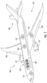
- FIG. 1 illustrates one type of aircraft 100 that may benefit from example implementations of the present disclosure.
- the aircraft includes an airframe 102 with a fuselage 104, wings 106 and tail 108.
- the aircraft also includes a plurality of high-level systems 110 such as a propulsion system.
- the propulsion system of FIG. 1 may include two wing-mounted engines 112. In other examples, the propulsion system can include other arrangements, for example, engines carried by other portions of the aircraft including the fuselage and/or the tail.
- the high-level systems may also include an electrical system 114, hydraulic system 116 and/or environmental system 118. Any number of other systems may be included.
- the high-level systems described above may include a plurality of sensors and subsystems providing fault and sensor data that is communicated via an aircraft data communications bus network and/or an onboard network system (ONS) to an aircraft condition monitoring system (ACMS).
- the ACMS may collect, monitor, record and report real-time aircraft system data, which may include error messages from a flight deck effects (FDE) system, system test reports, fault reports and other information.
- FDE flight deck effects
- the data collected by the ACMS is used, for example, to perform cabin pressure and temperature monitoring, hard landing detection, flight crew monitoring, and engine monitoring in addition to many other aircraft performance functions.
- the received data is then utilized to analyze aircraft performance, record significant flight events, report aircraft system test reports and fault reports, and troubleshoot faults.
- the ACMS may be in communication with an onboard component / computer 120 which may also be referred to as a central maintenance computer (CMC), on which may reside an aircraft health management or maintenance management system and a diagnostic maintenance computing function (DMCF).
- the onboard computer 120 including the DMCF may receive aircraft system test reports and fault reports, and may further include an onboard diagnostic model.
- the DMCF may provide data acquisition for the onboard diagnostic model, which receives the test reports and fault report data.
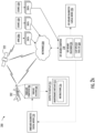
- FIG. 2A illustrates a system 200 for maintenance of an aircraft 202 that may correspond to aircraft 100, according to some example implementations.
- the system may include any of a number of different subsystems (each an individual system) for performing one or more functions or operations.
- the subsystems may be co-located or directly coupled to one another, or in some examples, various ones of the subsystems may communicate with one another across the one or more computer networks 204.
- any one or more of the subsystems may function or operate as a separate system without regard to any of the other subsystems.
- the system may include one or more additional or alternative subsystems than those shown in FIG. 2A .
- the system 200 includes an onboard computer 206 that may correspond to onboard component / computer 120.
- the onboard computer includes an onboard reasoner 208, and in some examples, the onboard computer is configured to diagnose a failure on the aircraft that includes aircraft systems configured to report faults to the onboard reasoner.
- suitable aircraft systems include propulsion system 110, electrical system 114, hydraulic system 116 and/or environmental system 118. Any number of other systems may be included.
- the onboard computer 206 is configured to receive a fault report from an aircraft system of the aircraft systems, the fault report indicating failed tests reported by the aircraft system.
- the onboard computer is configured to access, by the onboard reasoner 208, an onboard diagnostic causal model, which may be represented by a graph that describes known causal relationships between possible failed tests reported by the respective ones of the aircraft systems, and possible failure modes of the respective ones of the aircraft systems.
- the onboard diagnostic causal model is represented by the graph that includes nodes connected by edges, in which the nodes represent the possible failed tests and the possible failure modes, and the edges indicate the known causal relationships between the possible failed tests and the possible failure modes.
- the onboard diagnostic causal model is represented by the graph that is an assembly of graphs for respective ones of the aircraft systems, in which the graphs reflect fault propagation behavior within the respective ones of the aircraft systems, and the assembly reflects fault propagation behavior across connected ones of the aircraft systems.
- the onboard computer includes an onboard reasoner 208, with which the onboard computer is configured to diagnose a failure on the aircraft that includes aircraft systems configured to report faults to the onboard reasoner.
- the onboard computer 206 is configured to diagnose, by the onboard reasoner 208, a failure mode of the aircraft system or another of the aircraft systems, from the failed tests, and using the onboard diagnostic causal model 210 and a graph-theoretic algorithm such as an optimal solution set (OSS) algorithm.
- the onboard computer is also configured to generate a failure report associated with the diagnosed failure mode, based on which a maintenance message may be generated that indicates a maintenance action.
- an off-board computer 218 is configured to maintain the onboard reasoner 208.
- the off-board computer is configured to access diagnostic data received directly or indirectly from the onboard computer.
- This diagnostic data includes a plurality of fault reports of failed tests reported by respective ones of the aircraft systems, and a plurality of diagnosed failure modes of at least some of the aircraft systems that caused the failed tests.
- the off-board computer 218 includes an off-board reasoner 224, which is configured to determine causal relationships between the failed tests and the plurality of diagnosed failure modes.
- the off-board diagnostic causal model uses a machine learning algorithm trained using historical diagnostic data, which may be a machine learning algorithm such as a graph-theoretic algorithm for finding maximal cliques such as a Bron-Kerbosch algorithm.
- the machine learning algorithm for finding maximal cliques uses diagnostic data, including historical data that relates maintenance actions to maintenance messages or failure modes (obtained from a database of actual aircraft diagnostic data, which includes different failure modes; relationships between test reports, failure reports and components; maintenance action data, etc.), for determining known causal relationships between failure modes and failed tests.
- the off-board reasoner employing the machine learning algorithm is configured to use actual failure data, diagnostic data and/or maintenance action data received from an onboard aircraft system (from which to determine relationships between failure modes and failed tests), which is compared to the diagnostic data accessible from the aircraft onboard diagnostic system (onboard computer 206).
- the off-board reasoner may determine a discrepancy based on the comparison, which may then update and improve the onboard diagnostic causal model.
- the identification of a discrepancy may comprise identifying a new maintenance action, from historical diagnostic data and maintenance action data collected from an aircraft onboard system, wherein the discrepancy identification identifies a new maintenance action that is associated with the failure mode.
- FIG. 3 shows an example graph-based representation of an onboard diagnostic causal model 300 suitable as the onboard diagnostic casual model 210, according to some example implementations.
- a fault report 302 from an aircraft brake system antiskid wheelspeed transducer 304 may indicate failed gear retract braking tests 306A, 306B.
- the onboard diagnostic casual model may include nodes 308A-C connected by edges 310.
- the nodes may include nodes 308A, 308B that represent the failed gear retract braking tests, and a node 308C that represents a failure mode with a known causal relationship to the failed tests, as indicated by the edges connecting the nodes.
- the failed tests share a common failure mode of a spurious operation of the aircraft brake system antiskid wheel speed transducer.
- This failure mode may be diagnosed from the failed tests and using the onboard causal model.
- a maintenance action may be implemented for the failure mode, and a maintenance message 312 that references instructions 314 for performing the maintenance action may be generated.
- Such maintenance action data may be collected from the aircraft condition monitoring system or other system as historical maintenance action data and/or diagnostic data, where actual historic diagnostic data and maintenance action data may be used in determining actual causal relationships.
- the onboard computer 206 is configured to diagnose, by the onboard reasoner 208, a failure mode of the aircraft system or another of the aircraft systems, from the failed tests, and using a graph-theoretic algorithm and the onboard diagnostic causal model 210.
- a graph-theoretic algorithm is an optimal solution set (OSS) algorithm.
- the OSS algorithm may utilize submodular minimization of data to provide an efficient distributed optimization algorithm, where data on various failed test reports may be associated to an element or category of test reports or failure modes, and only data of subsets containing a specific failed test report or failure mode itself is considered while ignoring all other data.
- the optimization algorithm may further create graphs of nodes for graph-theoretic analysis, and may use neighboring node and/or edge probability analysis to determine a diagnosed failure mode, which would describe a diagnosis causal relationship between failed tests reported by the aircraft and possible failure modes for a reported aircraft system.
- the onboard computer is also configured to determine a maintenance action for the failure mode and generate a maintenance message 212 including at least the maintenance action.
- the onboard computer 206 is further configured to send the maintenance message 212 to a display device 214 onboard the aircraft, or to a display device on a maintenance component configured to establish a connection with the onboard computer to receive and display the maintenance message 212.
- display of the maintenance message references instructions 216 for performing the maintenance action to address the failure mode diagnosed by the onboard reasoner 208.
- the system 200 in some examples includes an off-board computer 218 configured to maintain the onboard reasoner 208.
- the off-board computer is configured to access diagnostic data received directly or indirectly from the onboard computer. This diagnostic data includes a plurality of fault reports of failed tests reported by respective ones of the aircraft systems, and a plurality of diagnosed failure modes of at least some of the aircraft systems that caused the failed tests.
- the system 200 includes at least one source 220 of data.
- the source includes a memory that may be located at a single source or distributed across multiple sources.
- the data may be stored in a number of different manners, such as in a database or flat files of any of a number of different types or formats.
- an aircraft condition monitoring system (ACMS) onboard the aircraft 202 may collect, monitor, record, and report diagnostic data.
- At least some of the diagnostic data may be accessible from reports generated by the ACMS and may be wirelessly transmitted to a particular source of data-shown and at times referred to as an airplane health management (AHM) system 220A-directly or via an artificial satellite 222 or network(s) 204.
- the diagnostic data may be transmitted via a wired connection or portable data storage device (e.g., flash memory, thumb drive).
- the off-board computer 218 includes an off-board reasoner 224.
- the off-board computer is configured to build, using the off-board reasoner, an off-board diagnostic causal model 226, which may be that describes causal relationships between the failed tests and the plurality of diagnosed failure modes.
- the off-board diagnostic causal model is here built using a graph-theoretic machine learning algorithm trained using historical diagnostic data.
- the off-board diagnostic causal model is represented by the graph that includes nodes connected by edges, in which the nodes representing the failed tests and the plurality of diagnosed failure modes, and the edges indicating the known causal relationships between the failed tests and the plurality of diagnosed failure modes.
- the offboard diagnostic causal model 226 employs a machine learning algorithm that uses failure data, historical diagnostic data and/or maintenance action data received from an onboard aircraft system, which is compared to diagnostic data accessible from the aircraft onboard diagnostic system (onboard computer 206).
- the off-board diagnostic causal model 226 may determine a discrepancy based its comparison to the diagnostic data.
- a graph-based representation of a fault report 302 from an aircraft brake system antiskid wheelspeed transducer 304 indicates failed gear retract braking tests 306A, 306B.
- the off-board diagnostic causal model 226 can identify a discrepancy based on collected maintenance action data such as a wheel speed transducer repair instruction (MM_32_30710), for defining a new relationship in the diagnostic causal model pertaining to the fault, to be incorporated into the aircraft's onboard diagnostic reasoner model.
- MM_32_30710 wheel speed transducer repair instruction
- a graph-theoretic machine learning algorithm for finding maximal cliques may use diagnostic data to determine known causal relationships between failure modes and failed tests.
- FIG. 4 shows diagnostic data and relationships may be transposed into a graph of a maximal clique 400 with nodes 402, 404, and edges 406 as described below, one of each being called out in the figure.
- the nodes 402 represent possible failed tests T1, T2, T3, and T4
- the nodes 404 represent possible failure modes F2, F4, F5, F8, and F10.
- the edges indicate known causal relationships between the possible failed tests and the possible failure modes.
- the maximal clique 400 can be determined from the graph, which in this example includes all of the nodes 402, 404 and edges 406 in the graph based on the diagnostic data. In other examples a maximal clique may include less than all of the nodes and edges. From the maximal clique, particular failure modes associated with failed tests may be isolated.
- the edges 406 may be examined to find the active failure mode(s) 404 associated with the reported failed tests at the nodes 402.
- the off-board reasoner 224 may determine that a clique is a maximal clique (e.g., maximal clique 400) if it has more than one node for a failed test.
- the maximal clique may be identified as a monochromatic clique if all of the nodes for the failed tests have one or more shared failure mode as determined from the edges connecting the nodes.
- a shared failure mode(s) becomes the failure mode of interest, and the monochromatic clique may then be used to identify the failed component associated with the failure mode of interest.
- maximal clique 400 is a monochromatic clique with a shared failure mode F8 as identified from edges 406 connecting the nodes 402 representing the failed tests with the nodes 404 representing the shared failure mode F8.
- the off-board diagnostic causal model 226 may be matured by discovering any new relationships between failure modes and failed tests that were not present in the onboard diagnostic causal model 210 or are the result of emergent behavior in any of the aircraft systems. This can be mined from historical data that relates maintenance actions to maintenance messages 212 or failure modes, which may then update and improve the off-board diagnostic causal model.
- the off-board diagnostic causal model 226 may have a certain signature that defines the expected propagation of the failure modes.
- the off-board reasoner 224 may record the portions of the signature that it encounters while performing diagnosis.
- the off-board diagnostic causal model can be improved from this historical data (using a historical signature), which can be compared to a previous off-board diagnostic causal model so that any new relationship can be considered for addition to an updated off-board diagnostic causal model.
- the off-board computer 218 is configured to compare the diagnostic data from the onboard computer 206 to the off-board diagnostic causal model 226 to diagnose failure modes of the aircraft systems.
- the diagnostic data may describe known causal relationships between possible failed tests reported by the respective ones of the aircraft systems, and possible failure modes of the respective ones of the aircraft systems.
- the off-board computer 218 is configured to determine a new causal relationship in the causal relationships described by the off-board diagnostic causal model 226 that is new relative to the known causal relationships.
- the off-board computer is also configured to update the onboard diagnostic causal model to further describe the new causal relationship.
- LSAP loadable software airplane part
- the plurality of fault reports include a fault report that indicates those of the failed tests caused by a diagnosed failure mode of the plurality of diagnosed failure modes.
- the off-board computer 218 is further configured to diagnose, by the off-board reasoner 224, a corresponding failure mode of the aircraft system, from those of the failed tests caused by the diagnosed failure mode, and using the graph-theoretic machine learning algorithm and the graph. The off-board computer, then, is also configured to report any discrepancy between the corresponding failure mode diagnosed by the off-board reasoner, and the diagnosed failure mode of the plurality of diagnosed failure modes from the diagnostic data received from the onboard computer 206.
- the diagnostic data accessed by the off-board computer 218 further includes maintenance messages 212 with maintenance actions determined by the onboard reasoner 208 for respective ones of the plurality of diagnosed failure modes.
- the onboard diagnostic causal model 210 further describes relationships between the possible failure modes and respective ones of the maintenance actions. For a particular maintenance message with a particular maintenance action for a respective diagnosed failure mode, then, the off-board computer 218 is further configured to access a maintenance record with a performed maintenance action and thereby a new maintenance action for the respective diagnosed failure mode.
- the off-board computer is also configured to identify a maintenance action discrepancy between the particular maintenance action and the performed maintenance action, to determine a new relationship between the respective diagnosed failure mode and the performed maintenance action.
- the new relationship may be a new maintenance action, which is identified from historical diagnostic data and maintenance action data collected from an aircraft, where the new maintenance action is associated with the failure mode.
- the off-board computer is configured to update the onboard diagnostic causal model to describe the new relationship between the respective diagnosed failure mode and the performed maintenance action.
- the updated onboard diagnostic causal model may further include the new maintenance action that is identified from collected historical maintenance action data, which is associated with the failure mode.
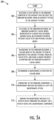
- FIGS. 5A , 5B , and 5C are flowcharts illustrating various steps in a method 500 of diagnosing a failure on an aircraft 202 that includes aircraft systems configured to report faults to an onboard reasoner 208, according to example implementations of the present disclosure.
- the method 500 includes receiving a fault report at an onboard computer 206 of the aircraft 202 that includes the onboard reasoner 208, from an aircraft system of the aircraft systems, the fault report indicating failed tests reported by the aircraft system.
- the method includes accessing, by the onboard reasoner, an onboard diagnostic causal model 210 represented by a graph that describes known causal relationships between possible failed tests reported by the respective ones of the aircraft systems, and possible failure modes of the respective ones of the aircraft systems.
- the method includes diagnosing, by the onboard reasoner 208, a failure mode of the aircraft system or another of the aircraft systems, from the failed tests, and using a graph-theoretic algorithm (e.g., an OSS algorithm) and the onboard diagnostic causal model 210.
- the method includes determining a maintenance action for the failure mode.
- the method includes generating, by the onboard computer 206, a maintenance message 212 including at least the maintenance action.
- the method 500 further includes sending the maintenance message 212 to a display device 214 onboard the aircraft 202, or a display device on a maintenance component configured to establish a connection with the onboard computer to receive the maintenance message, as shown at block 512.
- the fault report is one of a plurality of fault reports of failed tests reported by respective ones of the aircraft systems
- the failure mode is one of a plurality of diagnosed failure modes of at least some of the aircraft systems that caused the failed tests.
- the method 500 further includes accessing diagnostic data received from the onboard computer 206, and the diagnostic data includes the plurality of fault reports and the plurality of diagnosed failure modes.
- the method 500 further includes accessing, by the off-board reasoner 224, the off-board diagnostic causal model 226 describing causal relationships between the failed tests and the plurality of diagnosed failure modes.
- the off-board diagnostic causal model is built using a graph-theoretic machine learning algorithm trained using historical diagnostic data.
- the method further includes comparing the diagnostic data to the off-board diagnostic causal model, as shown at block 518.
- the method 500 further includes identifying a discrepancy between the diagnostic data and the off-board diagnostic causal model 226, to determine a new causal relationship in the causal relationships described by the off-board diagnostic causal model 226 that is new relative to the known causal relationships, as shown at block 520.
- the method further includes updating the onboard diagnostic causal model to further describe the new causal relationship, including producing an updated onboard diagnostic causal model, and uploading the updated onboard diagnostic causal model to the onboard component using the LSAP upload tool set 228.
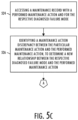
- the diagnostic data further includes maintenance messages 212 with maintenance actions determined by the onboard reasoner 208 for respective ones of the plurality of diagnosed failure modes, and the onboard diagnostic causal model 210 further describes relationships between the possible failure modes and respective ones of the maintenance actions.
- the method 500 further includes accessing a maintenance record with a performed maintenance action and thereby a new maintenance action for the respective diagnosed failure mode, as shown at block 524.
- the method further includes identifying a maintenance action discrepancy between the particular maintenance action and the performed maintenance action to determine a new relationship between the respective diagnosed failure mode and the performed maintenance action.
- the step of identifying a maintenance action discrepancy may also include identifying a new maintenance action from historical diagnostic data and maintenance action data collected from an aircraft condition monitoring system, wherein the discrepancy identification identifies a new maintenance action that is associated with the failure mode.
- updating the onboard diagnostic causal model further includes updating the onboard diagnostic causal model to describe the new relationship between the respective diagnosed failure mode and the performed maintenance action, as shown at block 522A.
- FIGS. 6A , 6B, and 6C are flowcharts illustrating various steps in a method 600 of maintaining the onboard reasoner 208 for diagnosing failures on the aircraft 202 that includes aircraft systems configured to report faults to the onboard reasoner.
- the method includes accessing diagnostic data received from the onboard computer 206 of the aircraft that includes the onboard reasoner, the diagnostic data including a plurality of fault reports of failed tests reported by respective ones of the aircraft systems, and a plurality of diagnosed failure modes of at least some of the aircraft systems that caused the failed tests.
- the method 600 includes building, using an off-board reasoner 224, an off-board diagnostic causal model 226 that describes causal relationships between the failed tests and the plurality of diagnosed failure modes.
- the off-board diagnostic causal model is built using a graph-theoretic machine learning algorithm trained using historical diagnostic data.
- the method 600 includes comparing the diagnostic data to the off-board diagnostic causal model 226. Based on the comparison at block 606, the method 600 includes determining a new causal relationship in the causal relationships described by the off-board diagnostic causal model 226 that is new relative to the known causal relationships, as shown at block 608. As shown at block 610, the method includes updating the onboard diagnostic causal model to further describe the new causal relationship, including producing an updated onboard diagnostic causal model, and uploading the updated onboard diagnostic causal model to the onboard computer using the LSAP upload tool set 228.
- the plurality of fault reports include a fault report that indicates those of the failed tests caused by a diagnosed failure mode of the plurality of diagnosed failure modes
- the method 600 further includes diagnosing, by the off-board reasoner 224, a corresponding failure mode of the aircraft system from those of the failed tests caused by the diagnosed failure mode, and using the graph-theoretic machine learning algorithm and the graph.
- the method further includes reporting any discrepancy between the corresponding failure mode diagnosed by the off-board reasoner and the diagnosed failure mode of the plurality of diagnosed failure modes from the diagnostic data received from the onboard computer 206.
- the diagnostic data further includes maintenance messages 212 with maintenance actions determined by the onboard reasoner 208 for respective ones of the plurality of diagnosed failure modes, and the onboard diagnostic causal model 210 further describes relationships between the possible failure modes and respective ones of the maintenance actions.
- the method 600 further includes accessing a maintenance record with a performed maintenance action and thereby a new maintenance action for the respective diagnosed failure mode, as shown at block 616.
- the method further includes identifying a maintenance action discrepancy between the particular maintenance action and the performed maintenance action, to determine a new relationship between the respective diagnosed failure mode and the performed maintenance action, as shown at block 618.
- updating the onboard diagnostic causal model further includes updating the onboard diagnostic causal model to describe the new relationship between the respective diagnosed failure mode and the performed maintenance action, as shown at block 610A.
- the method 600 may tie into method 500 in which the updated onboard diagnostic casual model may be used to diagnose a failure mode of an aircraft system. This may include receiving a fault report at the onboard computer 206 of the aircraft 202 that includes the onboard reasoner 208 (see block 502).
- the onboard reasoner may access the updated onboard diagnostic causal model 210, and diagnose a failure mode of the aircraft system or another of the aircraft systems, from the failed tests, and using a graph-theoretic algorithm and the updated onboard diagnostic causal model (see blocks 504 and 506).
- a maintenance action for the failure mode may be determined, a maintenance message 212 including at least the maintenance action may be generated (see blocks 508 and 510).
- the system 200 and its subsystems may be implemented by various means.
- Means for implementing the system and its subsystems may include hardware, alone or under direction of one or more computer programs from a computer-readable storage medium.
- one or more apparatuses may be configured to function as or otherwise implement the system and its subsystems shown and described herein.
- the respective apparatuses may be connected to or otherwise in communication with one another in a number of different manners, such as directly or indirectly via a wired or wireless network 514 or the like.
- FIG. 7 illustrates an apparatus 700 that in various example implementations may be configured to implement the onboard computer 206 and/or the off-board computer 218 shown in FIG. 2A .
- an apparatus of exemplary implementations of the present disclosure may comprise, include or be embodied in one or more fixed or portable electronic devices. Examples of suitable electronic devices include a smartphone, tablet computer, laptop computer, desktop computer, workstation computer, server computer or the like.
- the apparatus may include one or more of each of a number of components such as, for example, processing circuitry 702 (e.g., processor unit) connected to a memory 704 (e.g., storage device).
- processing circuitry 702 e.g., processor unit
- memory 704 e.g., storage device
- the processing circuitry 702 may be composed of one or more processors alone or in combination with one or more memories.
- the processing circuitry is generally any piece of computer hardware that is capable of processing information such as, for example, data, computer programs and/or other suitable electronic information.
- the processing circuitry is composed of a collection of electronic circuits some of which may be packaged as an integrated circuit or multiple interconnected integrated circuits (an integrated circuit at times more commonly referred to as a "chip").
- the processing circuitry may be configured to execute computer programs, which may be stored onboard the processing circuitry or otherwise stored in the memory 704 (of the same or another apparatus).
- the processing circuitry 702 may be a number of processors, a multi-core processor or some other type of processor, depending on the particular implementation. Further, the processing circuitry may be implemented using a number of heterogeneous processor systems in which a main processor is present with one or more secondary processors on a single chip. As another illustrative example, the processing circuitry may be a symmetric multi-processor system containing multiple processors of the same type. In yet other examples, the processing circuitry may be embodied as or otherwise include one or more ASICs, FPGAs or the like. Thus, although the processing circuitry may be capable of executing a computer program to perform one or more functions, the processing circuitry of various examples may be capable of performing one or more functions without the aid of a computer program. In either instance, the processing circuitry may be appropriately programmed to perform functions or operations according to example implementations of the present disclosure.
- the memory 704 is generally any piece of computer hardware that is capable of storing information such as, for example, data, computer programs (e.g., computer-readable program code 706) and/or other suitable information either on a temporary basis and/or a permanent basis.
- the memory may include volatile and/or non-volatile memory, and may be fixed or removable. Examples of suitable memory include random access memory (RAM), read-only memory (ROM), a hard drive, a flash memory, a thumb drive, a removable computer diskette, an optical disk, a magnetic tape or some combination of the above.
- Optical disks may include compact disk - read only memory (CD-ROM), compact disk - read/write (CD-R/W), DVD or the like.
- the memory may be referred to as a computer-readable storage medium.
- the computer-readable storage medium is a non-transitory device capable of storing information, and is distinguishable from computer-readable transmission media such as electronic transitory signals capable of carrying information from one location to another.
- Computer-readable medium as described herein may generally refer to a computer-readable storage medium or computer-readable transmission medium.
- the processing circuitry 702 may also be connected to one or more interfaces for displaying, transmitting and/or receiving information.
- the interfaces may include a communications interface 708 (e.g., communications unit) and/or one or more user interfaces.
- the communications interface may be configured to transmit and/or receive information, such as to and/or from other apparatus(es), network(s) or the like.
- the communications interface may be configured to transmit and/or receive information by physical (wired) and/or wireless communications links. Examples of suitable communication interfaces include a network interface controller (NIC), wireless NIC (WNIC) or the like.
- NIC network interface controller
- WNIC wireless NIC
- the user interfaces may include a display 710 and/or one or more user input interfaces 712 (e.g., input/output unit).
- the display may be configured to present or otherwise display information to a user, suitable examples of which include a liquid crystal display (LCD), light-emitting diode display (LED), plasma display panel (PDP) or the like.
- the user input interfaces may be wired or wireless, and may be configured to receive information from a user into the apparatus, such as for processing, storage and/or display. Suitable examples of user input interfaces include a microphone, image or video capture device, keyboard or keypad, joystick, touch-sensitive surface (separate from or integrated into a touchscreen), biometric sensor or the like.
- the user interfaces may further include one or more interfaces for communicating with peripherals such as printers, scanners or the like.
- program code instructions may be stored in memory, and executed by processing circuitry that is thereby programmed, to implement functions of the systems, subsystems, tools and their respective elements described herein.
- any suitable program code instructions may be loaded onto a computer or other programmable apparatus from a computer-readable storage medium to produce a particular machine, such that the particular machine becomes a means for implementing the functions specified herein.
- These program code instructions may also be stored in a computer-readable storage medium that can direct a computer, a processing circuitry or other programmable apparatus to function in a particular manner to thereby generate a particular machine or particular article of manufacture.
- the instructions stored in the computer-readable storage medium may produce an article of manufacture, where the article of manufacture becomes a means for implementing functions described herein.
- the program code instructions may be retrieved from a computer-readable storage medium and loaded into a computer, processing circuitry or other programmable apparatus to configure the computer, processing circuitry or other programmable apparatus to execute operations to be performed on or by the computer, processing circuitry or other programmable apparatus.
- Retrieval, loading and execution of the program code instructions may be performed sequentially such that one instruction is retrieved, loaded and executed at a time. In some example implementations, retrieval, loading and/or execution may be performed in parallel such that multiple instructions are retrieved, loaded, and/or executed together. Execution of the program code instructions may produce a computer-implemented process such that the instructions executed by the computer, processing circuitry or other programmable apparatus provide operations for implementing functions described herein.
- an apparatus 700 may include a processing circuitry 702 and a computer-readable storage medium or memory 704 coupled to the processing circuitry, where the processing circuitry is configured to execute computer-readable program code 706 stored in the memory. It will also be understood that one or more functions, and combinations of functions, may be implemented by special purpose hardware-based computer systems and/or processing circuitry which perform the specified functions, or combinations of special purpose hardware and program code instructions.
Landscapes
- Engineering & Computer Science (AREA)
- Physics & Mathematics (AREA)
- General Physics & Mathematics (AREA)
- Theoretical Computer Science (AREA)
- Evolutionary Computation (AREA)
- Geometry (AREA)
- Aviation & Aerospace Engineering (AREA)
- General Engineering & Computer Science (AREA)
- Computer Hardware Design (AREA)
- Artificial Intelligence (AREA)
- Automation & Control Theory (AREA)
- Manufacturing & Machinery (AREA)
- Software Systems (AREA)
- Computer Vision & Pattern Recognition (AREA)
- Transportation (AREA)
- Medical Informatics (AREA)
- Mathematical Physics (AREA)
- Computational Mathematics (AREA)
- Mathematical Analysis (AREA)
- Mathematical Optimization (AREA)
- Pure & Applied Mathematics (AREA)
- Testing And Monitoring For Control Systems (AREA)
- Management, Administration, Business Operations System, And Electronic Commerce (AREA)
- Test And Diagnosis Of Digital Computers (AREA)
Claims (15)
- Procédé (600) de maintenance d'un aéronef (202) qui comprend des systèmes d'aéronef configurés pour signaler des défaillances à un raisonneur de bord (208), le procédé comprenant l'étape consistant à :accéder (602) à des données de diagnostic reçues à partir d'un ordinateur de bord (206) de l'aéronef qui comprend le raisonneur de bord, les données de diagnostic comprenant une pluralité de rapports de défaillance (302) de tests ayant échoué (306A, 306B) signalés par certains respectifs des systèmes d'aéronef, et une pluralité de modes de défaillance diagnostiqués (308C) d'au moins certains des systèmes d'aéronef qui ont causé les tests ayant échoué ;le procédé étant en outre caractérisé par les étapes consistant à :construire (604), en utilisant un raisonneur hors-bord (224) d'un ordinateur hors-bord (218), un modèle causal de diagnostic hors-bord (226) qui décrit des relations de causalité entre les tests ayant échoué (402) et la pluralité de modes de défaillance diagnostiqués (404), le modèle causal de diagnostic hors-bord étant construit à l'aide d'un algorithme d'apprentissage automatique de théorie des graphes formé en utilisant des données de diagnostic historiques ;comparer (606), en utilisant le raisonneur hors-bord (224), les données de diagnostic au modèle causal de diagnostic hors-bord ; et sur la base de cela,déterminer (608), en utilisant le raisonneur hors-bord (224), une nouvelle relation causale dans les relations causales décrites par le modèle causal de diagnostic hors-bord qui est nouvelle par rapport aux relations causales connues ; etmettre à jour (610), en utilisant le raisonneur hors-bord (224), le modèle causal de diagnostic de bord pour décrire davantage la nouvelle relation causale, y compris produire un modèle causal de diagnostic de bord mis à jour, et télécharger le modèle causal de diagnostic de bord mis à jour sur l'ordinateur de bord à l'aide d'un ensemble d'outils de téléchargement de partie d'aéronef de logiciel chargeable (228),dans lequel le modèle causal de diagnostic hors-bord (226) est représenté par un graphique (400) qui comprend des noeuds (402, 404) connectés par des bords (406), les noeuds représentant les tests ayant échoué (402) et la pluralité de modes de défaillance diagnostiqués (404), et les bords indiquant les relations causales connues entre les tests ayant échoué et la pluralité de modes de défaillance diagnostiqués.
- Procédé (600) selon la revendication 1, comprenant en outre les étapes consistant à :recevoir (502) un rapport de défaillance (302) au niveau de l'ordinateur de bord (206, 700) de l'aéronef (202) qui comprend le raisonneur de bord (208), à partir d'un système d'aéronef des systèmes d'aéronef, le rapport de défaillance indiquant des tests ayant échoué (306A, 306B) rapportés par le système d'aéronef ;accéder (504), par l'intermédiaire du raisonneur de bord, au modèle de causalité de diagnostic de bord mis à jour (210, 300) ;diagnostiquer (506), par l'intermédiaire du raisonneur de bord en utilisant un algorithme de théorie des graphes et le modèle causal de diagnostic de bord mis à jour, un mode de défaillance (308C) du système d'aéronef ou d'un autre des systèmes d'aéronef, à partir des tests ayant échoué (308A, 308B) ;déterminer (508) une action de maintenance pour le mode de défaillance ; etgénérer (510), par l'intermédiaire de l'ordinateur de bord, un message de maintenance (212, 312) comprenant au moins l'action de maintenance.
- Procédé (600) selon la revendication 2, dans lequel l'algorithme de théorie des graphes est un algorithme d'ensemble de solutions optimales, OSS.
- Procédé selon la revendication 2 ou 3, comprenant en outre l'envoi, par l'intermédiaire de l'ordinateur de bord (206), du message de maintenance (212, 312) à un dispositif d'affichage (214) à bord de l'aéronef et l'affichage, par l'intermédiaire du dispositif d'affichage (214), du message de maintenance (212, 312).
- Procédé selon la revendication 2 ou 3, comprenant en outre l'envoi, par l'intermédiaire de l'ordinateur de bord (206), du message de maintenance (212, 312) à un dispositif d'affichage sur un composant de maintenance configuré pour établir une connexion avec l'ordinateur de bord afin de recevoir le message de maintenance (212, 312) et l'affichage, par l'intermédiaire du dispositif d'affichage (214), du message de maintenance (212, 312).
- Procédé selon la revendication 4 ou 5, dans lequel le message de maintenance (212, 312) fait référence à des instructions (216) pour mettre en œuvre l'action de maintenance afin d'aborder le mode de défaillance diagnostiqué par le raisonneur de bord (208).
- Procédé selon l'une quelconque des revendications 2 à 6, comprenant en outre la mise en œuvre de l'action de maintenance.
- Procédé (600) selon l'une quelconque des revendications 1 à 7, dans lequel la comparaison des données de diagnostic au modèle causal de diagnostic hors-bord comprend en outre la comparaison des données de diagnostic aux données de défaillance réelles, aux données de diagnostic et aux données d'action de maintenance collectées à partir d'un système d'aéronef de bord, qui reflètent des relations causales réelles.
- Procédé (600) selon l'une quelconque des revendications 1 à 8, dans lequel l'algorithme d'apprentissage automatique de théorie des graphes est un algorithme de théorie des graphes pour trouver des cliques maximales.
- Procédé (600) selon l'une quelconque des revendications 1 à 9, dans lequel la pluralité de rapports de défaillance comprend un rapport de défaillance (302) qui indique ceux des tests ayant échoué (306A, 306B) causés par un mode de défaillance diagnostiqué (308C) de la pluralité de modes de défaillance diagnostiqués, et le procédé comprend en outre les étapes consistant à :diagnostiquer (612), par l'intermédiaire du raisonneur hors-bord (224) en utilisant l'algorithme d'apprentissage automatique de théorie des graphes et un graphe (400), un mode de défaillance correspondant du système d'aéronef, à partir de ceux des tests ayant échoué (402) causés par le mode de défaillance diagnostiqué (404) ; etrapporter (614) toute différence entre le mode de défaillance correspondant et le mode de défaillance diagnostiqué de la pluralité de modes de défaillance diagnostiqués à partir des données de diagnostic reçues à partir de l'ordinateur de bord (206, 700).
- Procédé (600) selon l'une quelconque des revendications 1 à 10, dans lequel les données de diagnostic comprennent en outre des messages de maintenance (212, 312) avec des actions de maintenance déterminées par le raisonneur de bord (208) pour certains respectifs de la pluralité de modes de défaillance diagnostiqués (308C), et le modèle causal de diagnostic de bord (210, 300) décrit en outre des relations entre les modes de défaillance possibles et certaines respectives des actions de maintenance, et
dans lequel pour un message de maintenance particulier avec une action de maintenance particulière pour un mode de défaillance diagnostiqué respectif, le procédé comprend en outre les étapes consistant à :accéder (616) à un dossier de maintenance avec une action de maintenance mise en œuvre pour le mode de défaillance diagnostiqué respectif ; etidentifier (618) une différence d'action de maintenance entre l'action de maintenance particulière et l'action de maintenance mise en oeuvre, afin de déterminer une nouvelle relation entre le mode de défaillance diagnostiqué respectif et l'action de maintenance mise en oeuvre,dans lequel la mise à jour du modèle causal de diagnostic de bord comprend en outre la mise à jour (610A) du modèle causal de diagnostic de bord pour décrire la nouvelle relation entre le mode de défaillance diagnostiqué respectif et l'action de maintenance mise en oeuvre. - Produit de programme informatique comprenant des instructions de programme informatique qui, lorsqu'elles sont exécutées par un processeur informatique d'un système informatique, amènent le système informatique à mettre en œuvre le procédé selon l'une quelconque des revendications précédentes.
- Système informatique comprenant un support lisible par ordinateur ayant le programme informatique de la revendication 12 stocké en son sein.
- Système (200) pour la maintenance d'un aéronef (202) qui comprend des systèmes d'aéronef configurés pour rapporter des défaillances à un raisonneur de bord, le système (200) comprenant le système informatique de la revendication 13, et dans lequel le système informatique comprend un ordinateur de bord (206, 700) comprenant le raisonneur de bord (208) et un ordinateur hors-bord (218, 700) comprenant un raisonneur hors-bord (224).
- Système selon la revendication 14, comprenant un aéronef comportant l'ordinateur de bord (206, 700).
Applications Claiming Priority (2)
| Application Number | Priority Date | Filing Date | Title |
|---|---|---|---|
| US201962922231P | 2019-12-09 | 2019-12-09 | |
| US17/027,890 US11776330B2 (en) | 2019-12-09 | 2020-09-22 | Closed-loop diagnostic model maturation for complex systems |
Publications (2)
| Publication Number | Publication Date |
|---|---|
| EP3835904A1 EP3835904A1 (fr) | 2021-06-16 |
| EP3835904B1 true EP3835904B1 (fr) | 2025-01-01 |
Family
ID=73014370
Family Applications (1)
| Application Number | Title | Priority Date | Filing Date |
|---|---|---|---|
| EP20203701.6A Active EP3835904B1 (fr) | 2019-12-09 | 2020-10-23 | Maturation de modèles de diagnostic en boucle fermée pour systèmes complexes |
Country Status (3)
| Country | Link |
|---|---|
| US (1) | US11776330B2 (fr) |
| EP (1) | EP3835904B1 (fr) |
| CN (1) | CN113032891B (fr) |
Families Citing this family (8)
| Publication number | Priority date | Publication date | Assignee | Title |
|---|---|---|---|---|
| US12084205B2 (en) * | 2019-06-11 | 2024-09-10 | Qatar Foundation For Education, Science And Community Development | Methods and systems for identifying aircraft faults |
| BR112022012509A2 (pt) * | 2019-12-23 | 2022-09-06 | Embraer Sa | Sistemas e métodos para determinação de situação funcional e gerenciamento automático de falhas independente de sistema |
| US20220230485A1 (en) * | 2021-01-19 | 2022-07-21 | Magna Electronics Inc. | Vehicular control system with failure mode analysis |
| US12134484B2 (en) * | 2021-06-02 | 2024-11-05 | The Boeing Company | System and method for contextually-informed fault diagnostics using structural-temporal analysis of fault propagation graphs |
| US12283136B2 (en) * | 2021-11-16 | 2025-04-22 | The Boeing Company | Digital twin generation and logging for a vehicle |
| GB2614882A (en) * | 2022-01-19 | 2023-07-26 | Airbus Operations Ltd | Systems and methods for processing aircraft sensor data |
| CN115391083B (zh) * | 2022-10-27 | 2023-02-03 | 中国航空工业集团公司金城南京机电液压工程研究中心 | 一种机载机电设备健康管理方法及系统 |
| GB2624911A (en) | 2022-11-30 | 2024-06-05 | Airbus Operations Ltd | Aircraft control systems |
Citations (2)
| Publication number | Priority date | Publication date | Assignee | Title |
|---|---|---|---|---|
| EP2323005B1 (fr) * | 2009-11-16 | 2016-11-16 | Honeywell International Inc. | Procédé et système pour diagnostiquer et prognostiquer l' état de systèmes complexes avec des indicateurs de santé |
| EP2876519B1 (fr) * | 2013-11-18 | 2019-01-09 | The Boeing Company | Analyse de sécurité d'un système complexe à l'aide d'arbres de défaillances des composants |
Family Cites Families (17)
| Publication number | Priority date | Publication date | Assignee | Title |
|---|---|---|---|---|
| US5544308A (en) * | 1994-08-02 | 1996-08-06 | Giordano Automation Corp. | Method for automating the development and execution of diagnostic reasoning software in products and processes |
| US5919267A (en) * | 1997-04-09 | 1999-07-06 | Mcdonnell Douglas Corporation | Neural network fault diagnostics systems and related method |
| US6240343B1 (en) * | 1998-12-28 | 2001-05-29 | Caterpillar Inc. | Apparatus and method for diagnosing an engine using computer based models in combination with a neural network |
| US8583468B2 (en) | 2001-07-31 | 2013-11-12 | The Boeing Company | Method, system and computer program product for analyzing maintenance operations and assessing the readiness of repairable systems |
| JP4239932B2 (ja) * | 2004-08-27 | 2009-03-18 | 株式会社日立製作所 | 生産管理システム |
| US20070112608A1 (en) | 2005-11-16 | 2007-05-17 | Avery Robert L | Integrated maintenance services for fleet aircraft |
| US20080040152A1 (en) | 2006-08-10 | 2008-02-14 | The Boeing Company | Systems and Methods for Health Management of Single or Multi-Platform Systems |
| US20080159158A1 (en) | 2006-12-29 | 2008-07-03 | Clarence Edward Poisson | Method for testing a maintenance and materials management system |
| US20110087387A1 (en) | 2009-10-12 | 2011-04-14 | The Boeing Company | Platform Health Monitoring System |
| US20150185128A1 (en) | 2013-12-26 | 2015-07-02 | The Boeing Company | Detection and Assessment of Damage to Composite Structure |
| US10534787B2 (en) | 2014-02-25 | 2020-01-14 | The Boeing Company | Remote data delivery system |
| US9623983B2 (en) * | 2014-05-12 | 2017-04-18 | The Boeing Company | Aircraft interior monitoring |
| US9633489B2 (en) * | 2014-09-10 | 2017-04-25 | The Boeing Company | Configurable onboard information processing |
| US20160321594A1 (en) * | 2015-04-30 | 2016-11-03 | Optimal Plus Ltd. | Correlation between manufacturing segment and end- user device performance |
| US9747564B1 (en) * | 2016-02-12 | 2017-08-29 | The Boeing Company | Aircraft maintenance and inspection with data analytics enhancement |
| JP6831743B2 (ja) | 2017-04-19 | 2021-02-17 | 株式会社日立製作所 | 因果関係モデルの検証方法およびシステム、および不良原因抽出システム |
| US10643187B2 (en) * | 2017-06-09 | 2020-05-05 | Kidde Technologies, Inc. | Reporting and prioritizing faults for aircraft downtime reduction |
-
2020
- 2020-09-22 US US17/027,890 patent/US11776330B2/en active Active
- 2020-10-23 EP EP20203701.6A patent/EP3835904B1/fr active Active
- 2020-11-06 CN CN202011230949.2A patent/CN113032891B/zh active Active
Patent Citations (2)
| Publication number | Priority date | Publication date | Assignee | Title |
|---|---|---|---|---|
| EP2323005B1 (fr) * | 2009-11-16 | 2016-11-16 | Honeywell International Inc. | Procédé et système pour diagnostiquer et prognostiquer l' état de systèmes complexes avec des indicateurs de santé |
| EP2876519B1 (fr) * | 2013-11-18 | 2019-01-09 | The Boeing Company | Analyse de sécurité d'un système complexe à l'aide d'arbres de défaillances des composants |
Also Published As
| Publication number | Publication date |
|---|---|
| US20210174612A1 (en) | 2021-06-10 |
| CN113032891B (zh) | 2026-02-06 |
| EP3835904A1 (fr) | 2021-06-16 |
| US11776330B2 (en) | 2023-10-03 |
| CN113032891A (zh) | 2021-06-25 |
Similar Documents
| Publication | Publication Date | Title |
|---|---|---|
| EP3835904B1 (fr) | Maturation de modèles de diagnostic en boucle fermée pour systèmes complexes | |
| EP3836095B1 (fr) | Diagnostic embarqué et corrélation des données de panne aux actions de maintenance | |
| JP7438205B2 (ja) | モデルベース推論器のためのパラメトリックデータモデリング | |
| Esperon-Miguez et al. | A review of Integrated Vehicle Health Management tools for legacy platforms: Challenges and opportunities | |
| EP2489014B1 (fr) | Appareil et méthode de surveillance de santé de plate-forme | |
| JP7668822B2 (ja) | 車両の改善されたメンテナンスのための車両群レベル故障予測 | |
| CN114104329B (zh) | 基于传感器数据的修复的自动预测 | |
| US12148252B2 (en) | Repeated diagnostic reasoner use throughout service and maintenance of a vehicle | |
| US20250292104A1 (en) | Automated feature generation for sensor subset selection | |
| JP2019511061A (ja) | 保守に重点を置いた航空機のデータ記録フレーム構成を決定するためのシステムおよび方法 | |
| CN103778045A (zh) | 平台健康监视系统 | |
| EP2535853A1 (fr) | Procédés, systèmes et appareil permettant de classer des tests utilisés pour identifier des anomalies dans un système | |
| US12554998B2 (en) | Data analytics for more-informed repair of a mechanical or electromechanical system | |
| EP4099116B1 (fr) | Système et procédé de diagnostic de défauts informés par le contexte, utilisant l'analyse structurelle-temporelle de graphes de propagation de défauts | |
| US10339461B2 (en) | System for maintenance of a manufactured product | |
| CN111913953A (zh) | 一种诊断数据库生成方法及装置 | |
| Marcia | Metadata of the chapter that will be visualized in SpringerLink | |
| Bartolini et al. | An application of diagnostic inference modeling to vehicle health management | |
| Diévart et al. | Distributed embedded health assessment of networked instruments |
Legal Events
| Date | Code | Title | Description |
|---|---|---|---|
| PUAI | Public reference made under article 153(3) epc to a published international application that has entered the european phase |
Free format text: ORIGINAL CODE: 0009012 |
|
| STAA | Information on the status of an ep patent application or granted ep patent |
Free format text: STATUS: THE APPLICATION HAS BEEN PUBLISHED |
|
| AK | Designated contracting states |
Kind code of ref document: A1 Designated state(s): AL AT BE BG CH CY CZ DE DK EE ES FI FR GB GR HR HU IE IS IT LI LT LU LV MC MK MT NL NO PL PT RO RS SE SI SK SM TR |
|
| STAA | Information on the status of an ep patent application or granted ep patent |
Free format text: STATUS: REQUEST FOR EXAMINATION WAS MADE |
|
| 17P | Request for examination filed |
Effective date: 20211215 |
|
| RBV | Designated contracting states (corrected) |
Designated state(s): AL AT BE BG CH CY CZ DE DK EE ES FI FR GB GR HR HU IE IS IT LI LT LU LV MC MK MT NL NO PL PT RO RS SE SI SK SM TR |
|
| STAA | Information on the status of an ep patent application or granted ep patent |
Free format text: STATUS: EXAMINATION IS IN PROGRESS |
|
| 17Q | First examination report despatched |
Effective date: 20221014 |
|
| RAP3 | Party data changed (applicant data changed or rights of an application transferred) |
Owner name: THE BOEING COMPANY |
|
| GRAP | Despatch of communication of intention to grant a patent |
Free format text: ORIGINAL CODE: EPIDOSNIGR1 |
|
| STAA | Information on the status of an ep patent application or granted ep patent |
Free format text: STATUS: GRANT OF PATENT IS INTENDED |
|
| INTG | Intention to grant announced |
Effective date: 20240313 |
|
| P01 | Opt-out of the competence of the unified patent court (upc) registered |
Effective date: 20240402 |
|
| GRAJ | Information related to disapproval of communication of intention to grant by the applicant or resumption of examination proceedings by the epo deleted |
Free format text: ORIGINAL CODE: EPIDOSDIGR1 |
|
| STAA | Information on the status of an ep patent application or granted ep patent |
Free format text: STATUS: EXAMINATION IS IN PROGRESS |
|
| GRAP | Despatch of communication of intention to grant a patent |
Free format text: ORIGINAL CODE: EPIDOSNIGR1 |
|
| STAA | Information on the status of an ep patent application or granted ep patent |
Free format text: STATUS: GRANT OF PATENT IS INTENDED |
|
| INTC | Intention to grant announced (deleted) | ||
| INTG | Intention to grant announced |
Effective date: 20240723 |
|
| GRAS | Grant fee paid |
Free format text: ORIGINAL CODE: EPIDOSNIGR3 |
|
| GRAA | (expected) grant |
Free format text: ORIGINAL CODE: 0009210 |
|
| STAA | Information on the status of an ep patent application or granted ep patent |
Free format text: STATUS: THE PATENT HAS BEEN GRANTED |
|
| AK | Designated contracting states |
Kind code of ref document: B1 Designated state(s): AL AT BE BG CH CY CZ DE DK EE ES FI FR GB GR HR HU IE IS IT LI LT LU LV MC MK MT NL NO PL PT RO RS SE SI SK SM TR |
|
| REG | Reference to a national code |
Ref country code: GB Ref legal event code: FG4D |
|
| REG | Reference to a national code |
Ref country code: DE Ref legal event code: R096 Ref document number: 602020043955 Country of ref document: DE |
|
| REG | Reference to a national code |
Ref country code: CH Ref legal event code: EP |
|
| REG | Reference to a national code |
Ref country code: IE Ref legal event code: FG4D |
|
| REG | Reference to a national code |
Ref country code: LT Ref legal event code: MG9D |
|
| REG | Reference to a national code |
Ref country code: NL Ref legal event code: MP Effective date: 20250101 |
|
| REG | Reference to a national code |
Ref country code: AT Ref legal event code: MK05 Ref document number: 1756892 Country of ref document: AT Kind code of ref document: T Effective date: 20250101 |
|
| PG25 | Lapsed in a contracting state [announced via postgrant information from national office to epo] |
Ref country code: NL Free format text: LAPSE BECAUSE OF FAILURE TO SUBMIT A TRANSLATION OF THE DESCRIPTION OR TO PAY THE FEE WITHIN THE PRESCRIBED TIME-LIMIT Effective date: 20250101 |
|
| PG25 | Lapsed in a contracting state [announced via postgrant information from national office to epo] |
Ref country code: FI Free format text: LAPSE BECAUSE OF FAILURE TO SUBMIT A TRANSLATION OF THE DESCRIPTION OR TO PAY THE FEE WITHIN THE PRESCRIBED TIME-LIMIT Effective date: 20250101 |
|
| PG25 | Lapsed in a contracting state [announced via postgrant information from national office to epo] |
Ref country code: PL Free format text: LAPSE BECAUSE OF FAILURE TO SUBMIT A TRANSLATION OF THE DESCRIPTION OR TO PAY THE FEE WITHIN THE PRESCRIBED TIME-LIMIT Effective date: 20250101 |
|
| PG25 | Lapsed in a contracting state [announced via postgrant information from national office to epo] |
Ref country code: ES Free format text: LAPSE BECAUSE OF FAILURE TO SUBMIT A TRANSLATION OF THE DESCRIPTION OR TO PAY THE FEE WITHIN THE PRESCRIBED TIME-LIMIT Effective date: 20250101 |
|
| PG25 | Lapsed in a contracting state [announced via postgrant information from national office to epo] |
Ref country code: IS Free format text: LAPSE BECAUSE OF FAILURE TO SUBMIT A TRANSLATION OF THE DESCRIPTION OR TO PAY THE FEE WITHIN THE PRESCRIBED TIME-LIMIT Effective date: 20250501 Ref country code: NO Free format text: LAPSE BECAUSE OF FAILURE TO SUBMIT A TRANSLATION OF THE DESCRIPTION OR TO PAY THE FEE WITHIN THE PRESCRIBED TIME-LIMIT Effective date: 20250401 |
|
| PG25 | Lapsed in a contracting state [announced via postgrant information from national office to epo] |
Ref country code: HR Free format text: LAPSE BECAUSE OF FAILURE TO SUBMIT A TRANSLATION OF THE DESCRIPTION OR TO PAY THE FEE WITHIN THE PRESCRIBED TIME-LIMIT Effective date: 20250101 |
|
| PG25 | Lapsed in a contracting state [announced via postgrant information from national office to epo] |
Ref country code: LV Free format text: LAPSE BECAUSE OF FAILURE TO SUBMIT A TRANSLATION OF THE DESCRIPTION OR TO PAY THE FEE WITHIN THE PRESCRIBED TIME-LIMIT Effective date: 20250101 Ref country code: PT Free format text: LAPSE BECAUSE OF FAILURE TO SUBMIT A TRANSLATION OF THE DESCRIPTION OR TO PAY THE FEE WITHIN THE PRESCRIBED TIME-LIMIT Effective date: 20250502 |
|
| PG25 | Lapsed in a contracting state [announced via postgrant information from national office to epo] |
Ref country code: GR Free format text: LAPSE BECAUSE OF FAILURE TO SUBMIT A TRANSLATION OF THE DESCRIPTION OR TO PAY THE FEE WITHIN THE PRESCRIBED TIME-LIMIT Effective date: 20250402 Ref country code: BG Free format text: LAPSE BECAUSE OF FAILURE TO SUBMIT A TRANSLATION OF THE DESCRIPTION OR TO PAY THE FEE WITHIN THE PRESCRIBED TIME-LIMIT Effective date: 20250101 |
|
| PG25 | Lapsed in a contracting state [announced via postgrant information from national office to epo] |
Ref country code: AT Free format text: LAPSE BECAUSE OF FAILURE TO SUBMIT A TRANSLATION OF THE DESCRIPTION OR TO PAY THE FEE WITHIN THE PRESCRIBED TIME-LIMIT Effective date: 20250101 |
|
| PG25 | Lapsed in a contracting state [announced via postgrant information from national office to epo] |
Ref country code: CZ Free format text: LAPSE BECAUSE OF FAILURE TO SUBMIT A TRANSLATION OF THE DESCRIPTION OR TO PAY THE FEE WITHIN THE PRESCRIBED TIME-LIMIT Effective date: 20250101 |
|
| PG25 | Lapsed in a contracting state [announced via postgrant information from national office to epo] |
Ref country code: SE Free format text: LAPSE BECAUSE OF FAILURE TO SUBMIT A TRANSLATION OF THE DESCRIPTION OR TO PAY THE FEE WITHIN THE PRESCRIBED TIME-LIMIT Effective date: 20250101 |
|
| REG | Reference to a national code |
Ref country code: DE Ref legal event code: R097 Ref document number: 602020043955 Country of ref document: DE |
|
| PG25 | Lapsed in a contracting state [announced via postgrant information from national office to epo] |
Ref country code: SM Free format text: LAPSE BECAUSE OF FAILURE TO SUBMIT A TRANSLATION OF THE DESCRIPTION OR TO PAY THE FEE WITHIN THE PRESCRIBED TIME-LIMIT Effective date: 20250101 |
|
| PG25 | Lapsed in a contracting state [announced via postgrant information from national office to epo] |
Ref country code: DK Free format text: LAPSE BECAUSE OF FAILURE TO SUBMIT A TRANSLATION OF THE DESCRIPTION OR TO PAY THE FEE WITHIN THE PRESCRIBED TIME-LIMIT Effective date: 20250101 |
|
| PG25 | Lapsed in a contracting state [announced via postgrant information from national office to epo] |
Ref country code: IT Free format text: LAPSE BECAUSE OF FAILURE TO SUBMIT A TRANSLATION OF THE DESCRIPTION OR TO PAY THE FEE WITHIN THE PRESCRIBED TIME-LIMIT Effective date: 20250101 |
|
| PG25 | Lapsed in a contracting state [announced via postgrant information from national office to epo] |
Ref country code: EE Free format text: LAPSE BECAUSE OF FAILURE TO SUBMIT A TRANSLATION OF THE DESCRIPTION OR TO PAY THE FEE WITHIN THE PRESCRIBED TIME-LIMIT Effective date: 20250101 |
|
| PG25 | Lapsed in a contracting state [announced via postgrant information from national office to epo] |
Ref country code: RO Free format text: LAPSE BECAUSE OF FAILURE TO SUBMIT A TRANSLATION OF THE DESCRIPTION OR TO PAY THE FEE WITHIN THE PRESCRIBED TIME-LIMIT Effective date: 20250101 |
|
| PG25 | Lapsed in a contracting state [announced via postgrant information from national office to epo] |
Ref country code: SK Free format text: LAPSE BECAUSE OF FAILURE TO SUBMIT A TRANSLATION OF THE DESCRIPTION OR TO PAY THE FEE WITHIN THE PRESCRIBED TIME-LIMIT Effective date: 20250101 |
|
| PLBE | No opposition filed within time limit |
Free format text: ORIGINAL CODE: 0009261 |
|
| STAA | Information on the status of an ep patent application or granted ep patent |
Free format text: STATUS: NO OPPOSITION FILED WITHIN TIME LIMIT |
|
| 26N | No opposition filed |
Effective date: 20251002 |
|
| PGFP | Annual fee paid to national office [announced via postgrant information from national office to epo] |
Ref country code: DE Payment date: 20251029 Year of fee payment: 6 |
|
| PGFP | Annual fee paid to national office [announced via postgrant information from national office to epo] |
Ref country code: GB Payment date: 20251027 Year of fee payment: 6 |
|
| PGFP | Annual fee paid to national office [announced via postgrant information from national office to epo] |
Ref country code: FR Payment date: 20251027 Year of fee payment: 6 |