EP3836178B1 - Mécanisme de déconnexion automatique pour commutateurs - Google Patents
Mécanisme de déconnexion automatique pour commutateurs Download PDFInfo
- Publication number
- EP3836178B1 EP3836178B1 EP20165110.6A EP20165110A EP3836178B1 EP 3836178 B1 EP3836178 B1 EP 3836178B1 EP 20165110 A EP20165110 A EP 20165110A EP 3836178 B1 EP3836178 B1 EP 3836178B1
- Authority
- EP
- European Patent Office
- Prior art keywords
- reset
- shell
- spindle
- ratchet
- rotary
- Prior art date
- Legal status (The legal status is an assumption and is not a legal conclusion. Google has not performed a legal analysis and makes no representation as to the accuracy of the status listed.)
- Active
Links
Images



Classifications
-
- H—ELECTRICITY
- H01—ELECTRIC ELEMENTS
- H01H—ELECTRIC SWITCHES; RELAYS; SELECTORS; EMERGENCY PROTECTIVE DEVICES
- H01H33/00—High-tension or heavy-current switches with arc-extinguishing or arc-preventing means
- H01H33/02—Details
-
- H—ELECTRICITY
- H01—ELECTRIC ELEMENTS
- H01H—ELECTRIC SWITCHES; RELAYS; SELECTORS; EMERGENCY PROTECTIVE DEVICES
- H01H3/00—Mechanisms for operating contacts
- H01H3/22—Power arrangements internal to the switch for operating the driving mechanism
- H01H3/30—Power arrangements internal to the switch for operating the driving mechanism using spring motor
- H01H3/3042—Power arrangements internal to the switch for operating the driving mechanism using spring motor using a torsion spring
-
- H—ELECTRICITY
- H01—ELECTRIC ELEMENTS
- H01H—ELECTRIC SWITCHES; RELAYS; SELECTORS; EMERGENCY PROTECTIVE DEVICES
- H01H9/00—Details of switching devices, not covered by groups H01H1/00 - H01H7/00
- H01H9/20—Interlocking, locking, or latching mechanisms
-
- H—ELECTRICITY
- H01—ELECTRIC ELEMENTS
- H01H—ELECTRIC SWITCHES; RELAYS; SELECTORS; EMERGENCY PROTECTIVE DEVICES
- H01H3/00—Mechanisms for operating contacts
- H01H3/22—Power arrangements internal to the switch for operating the driving mechanism
- H01H3/30—Power arrangements internal to the switch for operating the driving mechanism using spring motor
-
- H—ELECTRICITY
- H01—ELECTRIC ELEMENTS
- H01H—ELECTRIC SWITCHES; RELAYS; SELECTORS; EMERGENCY PROTECTIVE DEVICES
- H01H33/00—High-tension or heavy-current switches with arc-extinguishing or arc-preventing means
- H01H33/02—Details
- H01H33/28—Power arrangements internal to the switch for operating the driving mechanism
-
- H—ELECTRICITY
- H01—ELECTRIC ELEMENTS
- H01H—ELECTRIC SWITCHES; RELAYS; SELECTORS; EMERGENCY PROTECTIVE DEVICES
- H01H2300/00—Orthogonal indexing scheme relating to electric switches, relays, selectors or emergency protective devices covered by H01H
- H01H2300/018—Application transfer; between utility and emergency power supply
-
- H—ELECTRICITY
- H01—ELECTRIC ELEMENTS
- H01H—ELECTRIC SWITCHES; RELAYS; SELECTORS; EMERGENCY PROTECTIVE DEVICES
- H01H3/00—Mechanisms for operating contacts
- H01H3/22—Power arrangements internal to the switch for operating the driving mechanism
- H01H3/30—Power arrangements internal to the switch for operating the driving mechanism using spring motor
- H01H3/3031—Means for locking the spring in a charged state
-
- H—ELECTRICITY
- H01—ELECTRIC ELEMENTS
- H01H—ELECTRIC SWITCHES; RELAYS; SELECTORS; EMERGENCY PROTECTIVE DEVICES
- H01H33/00—High-tension or heavy-current switches with arc-extinguishing or arc-preventing means
- H01H33/02—Details
- H01H33/28—Power arrangements internal to the switch for operating the driving mechanism
- H01H33/40—Power arrangements internal to the switch for operating the driving mechanism using spring motor
Definitions
- the invention relates to the technical field of circuit protection, in particular to an automatic disconnection mechanism for switches.
- DC switches are used in inverters to control the working states of multiple core components.
- the reliability of DC switches is not only related to the good operation of the entire power system, but also to the stable development of the power industry.
- US 4 683 357 discloses an automatic disconnection mechanism for switches, comprising a shell, wherein the inside of the shell is hollow, and the shell is provided with a spindle, a cam sleeved on the spindle, a rotary ratchet sleeved on the spindle, a torsional spring sleeved on the spindle, a control ratchet needle that mates with the rotary ratchet, and a limiting mechanism for limiting the rotation range of the cam;
- the rotary ratchet is provided with and external tooth that mates with the control ratchet needle on the outer periphery;
- the spindle penetrates the shell and is integrated with the shaft of the switch;
- the cam is fixedly connected to the spindle, and one end surface thereof is provided with a guide pin;
- the rotary ratchet is disposed on a side of the cam on which the guide pin is provided, the rotary ratchet and the spindle are
- an automatic disconnection mechanism for switches which is installed together with a photovoltaic switch as an automatic disconnection system for the photovoltaic switch, comprising a shell, wherein the inside of the shell is hollow, and the shell is provided with a spindle, a cam sleeved on the spindle, a rotary ratchet sleeved on the spindle, a torsional spring sleeved on the spindle, a control ratchet needle that mates with the rotary ratchet, and a limiting mechanism for limiting the rotation range of the cam;
- the rotary ratchet is provided with external teeth that mates with the control ratchet needle on the outer periphery;
- the spindle penetrates the shell and is integrated with the shaft of the photovoltaic switch;
- the cam is fixedly connected to the spindle, and one end surface thereof is provided with a guide pin; the rotary ratchet is
- the shell is rectangular parallelepiped, the front end surface thereof is provided with a first cover that mates with the shell, and the rear end surface thereof is provided with a second cover that mates with the shell; the second cover is provided with a second hole that mates with the spindle by a hole-fitting manner.
- connection portion of the lock plate and the release plate is provided with a connection shaft hole, and the connection shaft hole is sleeved on the short shaft connected to the shell so that the control ratchet needle can rotate around the short shaft;
- the length of the lock plate is shorter than that of the release plate, and an included angle is arranged between the lock plate and the release plate, and the included angle is an obtuse angle.
- the limiting mechanism is a long elliptical bulge; one end of the torsional spring is connected to the shell and the other end thereof is fixedly connected to the cam; the reset mechanism is a reset cam that rotates around a reset shaft, and one end of the reset shaft is connected to the shell and the other end thereof protrudes from the shell; the trigger mechanism is a flux transformer; the shell is further provided with a microswitch, and the microswitch is disposed on a side of the reset mechanism close to the lock plate; a first interlock knob is connected to the spindle protruding from the shell, and a second interlock knob is connected to the end of the reset shaft protruding from the shell.
- the reset mechanism is a side wall reset button corresponding to an end of the release plate of the control ratchet needle away from the lock plate; the side wall reset button is arranged in the same direction as the trigger mechanism and one end thereof protrudes from the shell; the side wall reset button is sleeved with a side wall reset spring connected to the corresponding inner wall of the shell, so that the side wall reset button is returned to its original position under the action of the reset spring after the side wall reset button is pressed in the direction of the trigger mechanism.
- the reset mechanism is a reset rotary handle that rotates around a reset shaft; a top reset button on a side of the reset rotary handle away from the trigger mechanism is provided in parallel with the spindle and protrudes from the top of the shell; the top reset button is provided with an inverted triangle driving block corresponding to the reset rotary handle; a top reset spring is also sleeved on the bottom of the top reset button, so that after the top reset button is pressed in its setting direction, the inverted triangle drive block dials the reset rotary handle to rotate toward the trigger mechanism and enables the top reset button to be returned to its original position under the action of the top reset spring.
- the invention has the following advantageous effects:
- the automatic disconnection mechanism of the invention enables the inverter circuit system to remotely disconnect the inverter system circuit without manual operation when it encounters special conditions such as overload and short circuit, which avoids accidents such as burnout of the inverter caused by circuit overload and short circuit and improves the safety of the operator.
- the automatic disconnection mechanism of the invention and the photovoltaic switch are installed together as an automatic disconnection system for the photovoltaic switch.
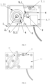
- an automatic disconnection mechanism for switches comprising a shell 1, wherein the inside of the shell 1 is hollow, and the shell 1 is provided with a spindle 2, a cam 3 sleeved on the spindle 2, a rotary ratchet 4 sleeved on the spindle 2, a torsional spring 5 sleeved on the spindle 2, a control ratchet needle 6 that mates with the rotary ratchet 4, and a limiting mechanism 1.3 for limiting the rotation range of the cam 3; the spindle 2 penetrates the shell 1 and is integrated with the switch shaft; the cam 3 is fixedly connected to the spindle 2, and one end surface thereof is provided with a guide pin 3.1; the rotary ratchet 4 is disposed on a side of the cam 3 on which the guide pin 3.1 is provided and mates with the hole of the spindle 2; the torsional spring 5 is disposed on a side of the rotary ratchet
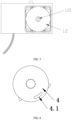
- the shell 1 is rectangular parallelepiped, the front end surface thereof is provided with a first cover 1.1 that mates with the shell, and the rear end surface thereof is provided with a second cover 1.2 that mates with the shell; the second cover 1.2 is provided with a second hole 1.21 that mates with the hole of the spindle 2.
- the rotary ratchet 4 is provided with external teeth that mates with the control ratchet needle 6 on the outer periphery; the rotary ratchet 4 is provided with a long elliptical hole 4.1 that mates with the guide pin 3.1, and the corresponding angle of the long elliptical hole 4.1 is 10°.
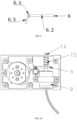
- connection portion of the lock plate 6.3 and the release plate 6.2 is provided with a connection shaft hole 6.4, and the connection shaft hole 6.4 is sleeved on the short shaft 6.1 connected to the shell so that the control ratchet needle 6 can rotate around the short shaft 6.1; the length of the lock plate 6.3 is shorter than that of the release plate 6.2.
- an included angle is arranged between the lock plate 6.3 and the release plate 6.2, and the included angle is an obtuse angle.
- the limiting mechanism 1.3 is a long elliptical bulge 1.31; one end of the torsional spring 5 is connected to the shell and the other end thereof is fixedly connected to the cam 5 ; the reset mechanism 7 is a reset cam 7.1 that rotates around a reset shaft 7.2, and one end of the reset shaft 7.2 is connected to the shell and the other end thereof protrudes from the shell 1; the trigger mechanism 8 is a flux transformer 8.6; the shell is further provided with a microswitch 9, and the microswitch 9 is disposed on a side of the reset mechanism 7 close to the lock plate 6.3; a first interlock knob 10 is connected to the spindle 2 protruding from the shell 1, and a second interlock knob 11 is connected to the end of the reset shaft 7.2 protruding from the shell 1.
- Embodiment 1 differs from Embodiment 1 in that:
- the reset mechanism 7 is a side wall reset button 7.4 corresponding to an end of the release plate 6.2 of the control ratchet needle 6 away from the lock plate 6.1; one end of the side wall reset button 7.4 protrudes from the shell 1; the side wall reset button 7.4 is sleeved with a side wall reset spring 7.5 connected to the corresponding inner wall of the shell 1, so that the side wall reset button 7.4 is returned to its original position under the action of the reset spring 7.5 after the side wall reset button is pressed in the direction of the trigger mechanism 8.
- Embodiment 1 differs from Embodiment 1 in that:
- the reset mechanism 7 is a reset rotary handle 7.6 that rotates around a reset shaft 7.2; a top reset button 7.7 on a side of the reset rotary handle 7.6 away from the trigger mechanism 8 is provided in parallel with the spindle 2 and protrudes from the top of the shell 1; the top reset button 7.7 is provided with an inverted triangle driving block 7.8 corresponding to the reset rotary handle 7.6; a top reset spring 7.9 is also sleeved on the bottom of the top reset button 7.7, so that after the top reset button 7.7 is pressed in its setting direction, the inverted triangle drive block 7.8 dials the reset rotary handle 7.6 to rotate toward the trigger mechanism 8 and enables the top reset button 7.7 to be returned to its original position under the action of the top reset spring7.9; moreover, the connection portion of the reset rotary handle 7.6 and the reset shaft 7.2 is also provided with a rotary handle reset spring, which enables that the reset rotary handle 7.6 to be returned to its original position under no force.
- the spindle controls the torsional spring (or volute spiral spring) of the automatic disconnection mechanism, so that the torsional spring (or volute spiral spring) of the automatic disconnection mechanism changes from a relaxed state to a tightened state, thereby completing the energy storage of the torsional spring (or volute spiral spring);
- the rotary ratchet connected to the spindle is fixed and locked by the control ratchet needle of the disconnection mechanism to prevent it from turning and releasing energy under the great torsion of the torsional spring (or volute spiral spring).
- the rotary ratchet After the energy storage of the torsional spring (or volute spiral spring) is completed, the rotary ratchet is locked by the control ratchet needle and fixed in the energy storage position.
- the control center can send a signal to the trigger mechanism of the DC switch; after the trigger mechanism is powered, it will immediately fire the action and impact the control ratchet needle to move it away from the rotary ratchet and eventually disengage from it.
- the rotary ratchet lacks the restriction of the control ratchet needle, and the clockwise rotation thereof is driven by the elastic force of the torsional spring (or volute spiral spring).
- the torsional spring (or volute spiral spring) can drive the switch spindle from the ON position to the OFF position to complete the disconnection operation of the switch.
- the spindle of the switch When the switch needs to be manually disconnected, the spindle of the switch needs to be turned counterclockwise, and the cam fixedly connected to the spindle pin will rotate.
- This device keeps the rotary ratchet temporarily unrotated within a rotation range of 10 degrees of rotation angle in front of the spindle, but starts to move after the ratchet teeth are pushed apart by the cam, and turns to the off position.
- the automatic disconnection mechanism When power is restored after the fault is removed, the automatic disconnection mechanism should be reset first: turning the reset button clockwise can reset it during rotation.
- the safety of the automatic disconnection mechanism with manual reset operation greatly improves the safety of the equipment, and it must be guaranteed that the fault is removed when a fault is found before the equipment is reset to be put into operation.
Landscapes
- Push-Button Switches (AREA)
- Mechanisms For Operating Contacts (AREA)
Claims (6)
- - Mécanisme de déconnexion automatique pour commutateurs, qui est installé conjointement avec un commutateur photovoltaïque en tant que système de déconnexion automatique pour le commutateur photovoltaïque, comprenant une coque (1), l'intérieur de la coque (1) étant creux, et la coque (1) comportant un axe (2), une came (3) emmanchée sur l'axe (2), une roue à rochet rotative (4) emmanchée sur l'axe (2), un ressort de torsion (5) emmanché sur l'axe (2), une aiguille de roue à rochet de commande (6) qui s'accouple à la roue à rochet rotative (4), et un mécanisme de limitation (1.3) pour limiter la plage de rotation de la came (3) ; la roue à rochet rotative (4) comportant des dents externes qui s'accouplent à l'aiguille de roue à rochet de commande (6) sur la périphérie extérieure ; l'axe (2) pénétrant dans la coque (1) et étant intégré à l'arbre du commutateur photovoltaïque ; la came (3) étant reliée de manière fixe à l'axe (2), et une surface d'extrémité de celle-ci comportant une goupille de guidage (3.1) ; la roue à rochet rotative (4) étant disposée sur un côté de la came (3) sur lequel la goupille de guidage (3.1) est prévue, la roue à rochet rotative (4) et l'axe (2) étant accouplés par une méthode d'ajustement de trou ; la roue à rochet rotative (4) comportant un trou elliptique long (4.1) qui s'accouple à la goupille de guidage (3.1), et l'angle correspondant du trou elliptique long (4.1) étant de 10° ; le ressort de torsion (5) étant disposé sur un côté de la roue à rochet rotative (4), une extrémité du ressort de torsion (5) étant reliée à la coque (1) et l'autre extrémité de celui-ci étant reliée de manière fixe à la came (3) ou une extrémité du ressort de torsion (5) étant reliée à la coque (1) et l'autre extrémité de celui-ci étant reliée de manière fixe à l'axe (2), et cela permettant au ressort de torsion (5) d'être dans un état tendu lorsque l'axe (2) tourne dans le sens des aiguilles d'une montre avec l'arbre du commutateur photovoltaïque ; l'aiguille de roue à rochet de commande (6) étant disposée sur un côté de la roue à rochet rotative (4) ; l'aiguille de roue à rochet de commande (6) comprenant une plaque de verrouillage (6.3) et une plaque de déverrouillage (6.2), et la partie de liaison de la plaque de verrouillage (6.3) et de la plaque de déverrouillage (6.2) étant emmanchée sur un arbre court (6.1) relié de manière fixe à la coque (1) ; la plaque de verrouillage (6.3) étant disposée en correspondance des dents externes du bord externe de la roue à rochet rotative (4), de telle sorte que, lorsque l'axe (2) tourne dans le sens des aiguilles d'une montre avec l'arbre du commutateur photovoltaïque, la roue à rochet rotative (4) est fixée et verrouillée par la plaque de verrouillage (6.3) ; les deux côtés de la plaque de déverrouillage (6.2) comportant également un mécanisme de déclenchement (8) destiné à frapper la plaque de déverrouillage (6.2) pour déplacer la plaque de verrouillage (6.3) à l'écart de la roue à rochet rotative (4) et finalement désengager celle-ci de la roue à rochet rotative (4), et un mécanisme de rappel (7) destiné à ramener la plaque de déverrouillage (6.2) à la position initiale après avoir été frappée par le mécanisme de déclenchement (8).
- - Mécanisme de déconnexion automatique pour commutateurs selon la revendication 1, dans lequel la coque (1) est un parallélépipède rectangle, la surface d'extrémité avant de celle-ci comporte un premier couvercle (1.1) qui s'accouple à la coque (1), et la surface d'extrémité arrière de celle-ci comporte un second couvercle (1.2) qui s'accouple à la coque (1) ; le second couvercle (1.2) comporte un second trou (1.21) qui s'accouple à l'axe (2) par ajustement de trou.
- - Mécanisme de déconnexion automatique pour commutateurs selon la revendication 1, dans lequel la partie de liaison de la plaque de verrouillage (6.3) et de la plaque de déverrouillage (6.2) comporte un trou d'arbre de liaison (6.4), et le trou d'arbre de liaison (6.4) est emmanché sur l'arbre court (6.1) relié à la coque (1), de telle sorte que l'aiguille de roue à rochet de commande (6) peut tourner autour de l'arbre court (6.1) ; la longueur de la plaque de verrouillage (6.3) est inférieure à celle de la plaque de déverrouillage (6.2), et un angle inclus est prévu entre la plaque de verrouillage (6.3) et la plaque de déverrouillage (6.2), et l'angle inclus est un angle obtus.
- - Mécanisme de déconnexion automatique pour commutateurs selon la revendication 1, dans lequel le mécanisme de limitation (1.3) est un renflement elliptique long (1.31) ; une extrémité du ressort de torsion (5) est reliée à la coque (1) et l'autre extrémité de celui-ci est reliée de manière fixe à la came (3) ; le mécanisme de rappel (7) est une came de rappel (7.1) qui tourne autour d'un arbre de rappel (7.2), et une extrémité de l'arbre de rappel (7.2) est reliée à la coque (1) et l'autre extrémité de celui-ci fait saillie à partir de la coque (1) ; le mécanisme de déclenchement (8) est un transformateur de flux (8.6) ; la coque (1) comporte en outre un micro-commutateur (9), et le micro-commutateur (9) est disposé sur un côté du mécanisme de rappel (7) proche de la plaque de verrouillage (6.3) ; un premier bouton de verrouillage (10) est relié à l'axe (2) faisant saillie à partir de la coque (1), et un second bouton de verrouillage (11) est relié à l'extrémité de l'arbre de rappel (7.2) faisant saillie à partir de la coque (1).
- - Mécanisme de déconnexion automatique pour commutateurs selon la revendication 1, dans lequel le mécanisme de rappel (7) est un bouton de rappel de paroi latérale (7.4) correspondant à une extrémité de la plaque de déverrouillage (6.2) de l'aiguille de roue à rochet de commande (6) à distance de la plaque de verrouillage (6.3) ; le bouton de rappel de paroi latérale (7.4) est disposé dans la même direction que le mécanisme de déclenchement (8) et une extrémité de celui-ci fait saillie à partir de la coque (1) ; le bouton de rappel de paroi latérale (7.4) est emmanché avec un ressort de rappel de paroi latérale (7.5) relié à la paroi interne correspondante de la coque (1), de telle sorte que le bouton de rappel de paroi latérale (7.4) revient à sa position initiale sous l'action du ressort de rappel (7.5) après que le bouton de rappel de paroi latérale (7.4) a été enfoncé en direction du mécanisme de déclenchement (8).
- - Mécanisme de déconnexion automatique pour commutateurs selon la revendication 1, dans lequel le mécanisme de rappel (7) est une poignée rotative de rappel (7.6) qui tourne autour d'un arbre de rappel (7.2) ; un bouton de rappel supérieur (7.7) sur un côté de la poignée rotative de rappel (7.6) à distance du mécanisme de déclenchement (8) est prévu en parallèle avec l'axe (2) et fait saillie à partir de la partie supérieure de la coque (1) ; le bouton de rappel supérieur (7.7) comporte un bloc d'entraînement en forme de triangle inversé (7.8) correspondant à la poignée rotative de rappel (7.6) ; un ressort de rappel supérieur (7.9) est également emmanché sur la partie inférieure du bouton de rappel supérieur (7.7), de telle sorte que, après que le bouton de rappel supérieur (7.7) a été enfoncé dans son sens de réglage, le bloc d'entraînement en forme de triangle inversé (7.8) amène la poignée rotative de rappel (7.6) à tourner vers le mécanisme de déclenchement (8) et permet au bouton de rappel supérieur (7.7) d'être ramené à sa position initiale sous l'action du ressort de rappel supérieur (7.9).
Applications Claiming Priority (1)
| Application Number | Priority Date | Filing Date | Title |
|---|---|---|---|
| CN201911263204.3A CN110942946A (zh) | 2019-12-11 | 2019-12-11 | 一种开关自动断开机构 |
Publications (3)
| Publication Number | Publication Date |
|---|---|
| EP3836178A1 EP3836178A1 (fr) | 2021-06-16 |
| EP3836178B1 true EP3836178B1 (fr) | 2025-05-28 |
| EP3836178C0 EP3836178C0 (fr) | 2025-05-28 |
Family
ID=69910114
Family Applications (1)
| Application Number | Title | Priority Date | Filing Date |
|---|---|---|---|
| EP20165110.6A Active EP3836178B1 (fr) | 2019-12-11 | 2020-03-24 | Mécanisme de déconnexion automatique pour commutateurs |
Country Status (3)
| Country | Link |
|---|---|
| US (1) | US20210183590A1 (fr) |
| EP (1) | EP3836178B1 (fr) |
| CN (1) | CN110942946A (fr) |
Families Citing this family (9)
| Publication number | Priority date | Publication date | Assignee | Title |
|---|---|---|---|---|
| CN111403196A (zh) * | 2020-04-01 | 2020-07-10 | 北京光华世通科技有限公司 | 一种复合轴操作的开关自动断开机构 |
| CN112193493A (zh) * | 2020-09-28 | 2021-01-08 | 温州倾晨贸易有限公司 | 一种智能生产的笔记本内存条包装装置 |
| CN112652494B (zh) * | 2020-09-29 | 2024-04-26 | 保定和易法电气科技有限公司 | 一种遥控的手车开关分合闸按钮操作装置 |
| CN112176895B (zh) * | 2020-10-19 | 2021-11-23 | 江苏盛达福交通工程有限公司 | 道路交通标线投影装置 |
| CN114516196B (zh) * | 2022-03-17 | 2024-01-23 | 美尔森石墨工业(重庆)有限公司 | 吊取石墨坯的安全防护装置 |
| CN115527793A (zh) * | 2022-10-17 | 2022-12-27 | 温州金宏电器有限公司 | 旋转开关用操作机构 |
| CN117052238B (zh) * | 2023-09-15 | 2025-06-03 | 江苏环海机械科技有限公司 | 全拆卸特种集装箱的门框锁紧装置 |
| CN118510192B (zh) * | 2024-04-28 | 2024-11-19 | 湖北师范大学 | 一种过欠压自动控制器 |
| CN119008279A (zh) * | 2024-08-07 | 2024-11-22 | 北京全路通信信号研究设计院集团有限公司 | 一种旋转表示机构、栏木机及其开关量确定方法 |
Family Cites Families (5)
| Publication number | Priority date | Publication date | Assignee | Title |
|---|---|---|---|---|
| US2668449A (en) * | 1950-02-18 | 1954-02-09 | S & C Electric Co | Snap-acting mechanism for opening electric switches and the like |
| US4683357A (en) * | 1985-12-19 | 1987-07-28 | S&C Electric Company | Switch-operating mechanism with improved charging arrangement |
| NZ337089A (en) * | 1999-08-06 | 2002-04-26 | Qei Inc | Air break switch actuator comprising operating means manually operable and/or driven by a linear drive unit |
| CN105428111A (zh) * | 2015-12-22 | 2016-03-23 | 江苏洛凯机电股份有限公司 | 断路器电动操作机构的控制系统 |
| CN212257262U (zh) * | 2019-12-11 | 2020-12-29 | 北京光华世通科技有限公司 | 一种开关自动断开机构 |
-
2019
- 2019-12-11 CN CN201911263204.3A patent/CN110942946A/zh active Pending
-
2020
- 2020-03-24 EP EP20165110.6A patent/EP3836178B1/fr active Active
- 2020-03-31 US US16/835,353 patent/US20210183590A1/en not_active Abandoned
Also Published As
| Publication number | Publication date |
|---|---|
| US20210183590A1 (en) | 2021-06-17 |
| CN110942946A (zh) | 2020-03-31 |
| EP3836178A1 (fr) | 2021-06-16 |
| EP3836178C0 (fr) | 2025-05-28 |
Similar Documents
| Publication | Publication Date | Title |
|---|---|---|
| EP3836178B1 (fr) | Mécanisme de déconnexion automatique pour commutateurs | |
| CN102845186B (zh) | 具有操作保护的割草机及其安全开关机构 | |
| CN111916317B (zh) | 断路器 | |
| EP2230056B1 (fr) | Scie à chaîne électrique | |
| CN204966424U (zh) | 电动操作装置及微型断路器 | |
| JP2009259820A (ja) | 回路遮断器の遮断準備表示器 | |
| CN212257262U (zh) | 一种开关自动断开机构 | |
| CN104601048A (zh) | 能快速分断的电机起动器的操作机构 | |
| EP3889982A1 (fr) | Mécanisme de déconnexion automatique pour commutateurs | |
| CN110739187A (zh) | 一种断路器指示装置及使用该装置的断路器 | |
| EP3989259B1 (fr) | Disjoncteur miniature enfichable | |
| CN109216124B (zh) | 一种电动操作装置驱动脱扣联动机构 | |
| CN213025989U (zh) | 断路器用漏电显示机构 | |
| CN219759495U (zh) | 防撞型智能弹操断路器 | |
| CN111933492A (zh) | 一种断路器的操动机构 | |
| CN112151336B (zh) | 一种操作机构及断路器 | |
| EP3319102B1 (fr) | Dispositif d'indication de commutation électrique | |
| CN111863556B (zh) | 一种断路器的辅助脱扣单元 | |
| CN116072460A (zh) | 用于旋转开关的转动储能装置 | |
| CN104616938B (zh) | 微型断路器及其操作方法 | |
| EP4492419A1 (fr) | Mécanisme d'ouverture automatique | |
| CN211125527U (zh) | 一种断路器指示装置及使用该装置的断路器 | |
| CN223155946U (zh) | 断路器操作机构 | |
| CN216288058U (zh) | 一种防爆组合开关壳体上的闭锁开关 | |
| CN222927398U (zh) | 一种快速脱扣机构装置 |
Legal Events
| Date | Code | Title | Description |
|---|---|---|---|
| PUAI | Public reference made under article 153(3) epc to a published international application that has entered the european phase |
Free format text: ORIGINAL CODE: 0009012 |
|
| STAA | Information on the status of an ep patent application or granted ep patent |
Free format text: STATUS: THE APPLICATION HAS BEEN PUBLISHED |
|
| AK | Designated contracting states |
Kind code of ref document: A1 Designated state(s): AL AT BE BG CH CY CZ DE DK EE ES FI FR GB GR HR HU IE IS IT LI LT LU LV MC MK MT NL NO PL PT RO RS SE SI SK SM TR |
|
| STAA | Information on the status of an ep patent application or granted ep patent |
Free format text: STATUS: REQUEST FOR EXAMINATION WAS MADE |
|
| 17P | Request for examination filed |
Effective date: 20211216 |
|
| RBV | Designated contracting states (corrected) |
Designated state(s): AL AT BE BG CH CY CZ DE DK EE ES FI FR GB GR HR HU IE IS IT LI LT LU LV MC MK MT NL NO PL PT RO RS SE SI SK SM TR |
|
| STAA | Information on the status of an ep patent application or granted ep patent |
Free format text: STATUS: EXAMINATION IS IN PROGRESS |
|
| 17Q | First examination report despatched |
Effective date: 20230606 |
|
| GRAP | Despatch of communication of intention to grant a patent |
Free format text: ORIGINAL CODE: EPIDOSNIGR1 |
|
| STAA | Information on the status of an ep patent application or granted ep patent |
Free format text: STATUS: GRANT OF PATENT IS INTENDED |
|
| INTG | Intention to grant announced |
Effective date: 20241219 |
|
| GRAS | Grant fee paid |
Free format text: ORIGINAL CODE: EPIDOSNIGR3 |
|
| GRAA | (expected) grant |
Free format text: ORIGINAL CODE: 0009210 |
|
| STAA | Information on the status of an ep patent application or granted ep patent |
Free format text: STATUS: THE PATENT HAS BEEN GRANTED |
|
| AK | Designated contracting states |
Kind code of ref document: B1 Designated state(s): AL AT BE BG CH CY CZ DE DK EE ES FI FR GB GR HR HU IE IS IT LI LT LU LV MC MK MT NL NO PL PT RO RS SE SI SK SM TR |
|
| REG | Reference to a national code |
Ref country code: GB Ref legal event code: FG4D |
|
| REG | Reference to a national code |
Ref country code: CH Ref legal event code: EP |
|
| REG | Reference to a national code |
Ref country code: DE Ref legal event code: R096 Ref document number: 602020051935 Country of ref document: DE |
|
| REG | Reference to a national code |
Ref country code: IE Ref legal event code: FG4D |
|
| U01 | Request for unitary effect filed |
Effective date: 20250624 |
|
| U07 | Unitary effect registered |
Designated state(s): AT BE BG DE DK EE FI FR IT LT LU LV MT NL PT RO SE SI Effective date: 20250702 |
|
| PG25 | Lapsed in a contracting state [announced via postgrant information from national office to epo] |
Ref country code: ES Free format text: LAPSE BECAUSE OF FAILURE TO SUBMIT A TRANSLATION OF THE DESCRIPTION OR TO PAY THE FEE WITHIN THE PRESCRIBED TIME-LIMIT Effective date: 20250528 |
|
| PG25 | Lapsed in a contracting state [announced via postgrant information from national office to epo] |
Ref country code: NO Free format text: LAPSE BECAUSE OF FAILURE TO SUBMIT A TRANSLATION OF THE DESCRIPTION OR TO PAY THE FEE WITHIN THE PRESCRIBED TIME-LIMIT Effective date: 20250828 Ref country code: GR Free format text: LAPSE BECAUSE OF FAILURE TO SUBMIT A TRANSLATION OF THE DESCRIPTION OR TO PAY THE FEE WITHIN THE PRESCRIBED TIME-LIMIT Effective date: 20250829 |
|
| PG25 | Lapsed in a contracting state [announced via postgrant information from national office to epo] |
Ref country code: PL Free format text: LAPSE BECAUSE OF FAILURE TO SUBMIT A TRANSLATION OF THE DESCRIPTION OR TO PAY THE FEE WITHIN THE PRESCRIBED TIME-LIMIT Effective date: 20250528 |
|
| PG25 | Lapsed in a contracting state [announced via postgrant information from national office to epo] |
Ref country code: HR Free format text: LAPSE BECAUSE OF FAILURE TO SUBMIT A TRANSLATION OF THE DESCRIPTION OR TO PAY THE FEE WITHIN THE PRESCRIBED TIME-LIMIT Effective date: 20250528 |
|
| PG25 | Lapsed in a contracting state [announced via postgrant information from national office to epo] |
Ref country code: RS Free format text: LAPSE BECAUSE OF FAILURE TO SUBMIT A TRANSLATION OF THE DESCRIPTION OR TO PAY THE FEE WITHIN THE PRESCRIBED TIME-LIMIT Effective date: 20250828 |
|
| PG25 | Lapsed in a contracting state [announced via postgrant information from national office to epo] |
Ref country code: IS Free format text: LAPSE BECAUSE OF FAILURE TO SUBMIT A TRANSLATION OF THE DESCRIPTION OR TO PAY THE FEE WITHIN THE PRESCRIBED TIME-LIMIT Effective date: 20250928 |
|
| PG25 | Lapsed in a contracting state [announced via postgrant information from national office to epo] |
Ref country code: SM Free format text: LAPSE BECAUSE OF FAILURE TO SUBMIT A TRANSLATION OF THE DESCRIPTION OR TO PAY THE FEE WITHIN THE PRESCRIBED TIME-LIMIT Effective date: 20250528 |
|
| PG25 | Lapsed in a contracting state [announced via postgrant information from national office to epo] |
Ref country code: CZ Free format text: LAPSE BECAUSE OF FAILURE TO SUBMIT A TRANSLATION OF THE DESCRIPTION OR TO PAY THE FEE WITHIN THE PRESCRIBED TIME-LIMIT Effective date: 20250528 |
|
| PG25 | Lapsed in a contracting state [announced via postgrant information from national office to epo] |
Ref country code: SK Free format text: LAPSE BECAUSE OF FAILURE TO SUBMIT A TRANSLATION OF THE DESCRIPTION OR TO PAY THE FEE WITHIN THE PRESCRIBED TIME-LIMIT Effective date: 20250528 |
|
| PLBE | No opposition filed within time limit |
Free format text: ORIGINAL CODE: 0009261 |
|
| STAA | Information on the status of an ep patent application or granted ep patent |
Free format text: STATUS: NO OPPOSITION FILED WITHIN TIME LIMIT |
|
| REG | Reference to a national code |
Ref country code: CH Ref legal event code: L10 Free format text: ST27 STATUS EVENT CODE: U-0-0-L10-L00 (AS PROVIDED BY THE NATIONAL OFFICE) Effective date: 20260409 |