EP3836182B1 - Commutateur de déconnexion à trois positions - Google Patents
Commutateur de déconnexion à trois positions Download PDFInfo
- Publication number
- EP3836182B1 EP3836182B1 EP19215336.9A EP19215336A EP3836182B1 EP 3836182 B1 EP3836182 B1 EP 3836182B1 EP 19215336 A EP19215336 A EP 19215336A EP 3836182 B1 EP3836182 B1 EP 3836182B1
- Authority
- EP
- European Patent Office
- Prior art keywords
- piston
- switch
- contact
- disconnector
- distance
- Prior art date
- Legal status (The legal status is an assumption and is not a legal conclusion. Google has not performed a legal analysis and makes no representation as to the accuracy of the status listed.)
- Active
Links
Images


Classifications
-
- H—ELECTRICITY
- H01—ELECTRIC ELEMENTS
- H01H—ELECTRIC SWITCHES; RELAYS; SELECTORS; EMERGENCY PROTECTIVE DEVICES
- H01H31/00—Air-break switches for high tension without arc-extinguishing or arc-preventing means
- H01H31/02—Details
- H01H31/023—Base and stationary contacts mounted thereon
-
- H—ELECTRICITY
- H01—ELECTRIC ELEMENTS
- H01H—ELECTRIC SWITCHES; RELAYS; SELECTORS; EMERGENCY PROTECTIVE DEVICES
- H01H31/00—Air-break switches for high tension without arc-extinguishing or arc-preventing means
- H01H31/003—Earthing switches
-
- H—ELECTRICITY
- H01—ELECTRIC ELEMENTS
- H01H—ELECTRIC SWITCHES; RELAYS; SELECTORS; EMERGENCY PROTECTIVE DEVICES
- H01H31/00—Air-break switches for high tension without arc-extinguishing or arc-preventing means
- H01H31/26—Air-break switches for high tension without arc-extinguishing or arc-preventing means with movable contact that remains electrically connected to one line in open position of switch
- H01H31/32—Air-break switches for high tension without arc-extinguishing or arc-preventing means with movable contact that remains electrically connected to one line in open position of switch with rectilinearly-movable contact
-
- H—ELECTRICITY
- H01—ELECTRIC ELEMENTS
- H01H—ELECTRIC SWITCHES; RELAYS; SELECTORS; EMERGENCY PROTECTIVE DEVICES
- H01H1/00—Contacts
- H01H1/58—Electric connections to or between contacts; Terminals
-
- H—ELECTRICITY
- H01—ELECTRIC ELEMENTS
- H01H—ELECTRIC SWITCHES; RELAYS; SELECTORS; EMERGENCY PROTECTIVE DEVICES
- H01H31/00—Air-break switches for high tension without arc-extinguishing or arc-preventing means
- H01H31/02—Details
- H01H31/026—Movable parts and contacts mounted thereon
-
- H—ELECTRICITY
- H01—ELECTRIC ELEMENTS
- H01H—ELECTRIC SWITCHES; RELAYS; SELECTORS; EMERGENCY PROTECTIVE DEVICES
- H01H33/00—High-tension or heavy-current switches with arc-extinguishing or arc-preventing means
- H01H33/02—Details
- H01H33/022—Details particular to three-phase circuit breakers
-
- H—ELECTRICITY
- H01—ELECTRIC ELEMENTS
- H01H—ELECTRIC SWITCHES; RELAYS; SELECTORS; EMERGENCY PROTECTIVE DEVICES
- H01H33/00—High-tension or heavy-current switches with arc-extinguishing or arc-preventing means
- H01H33/02—Details
- H01H33/42—Driving mechanisms
-
- H—ELECTRICITY
- H01—ELECTRIC ELEMENTS
- H01H—ELECTRIC SWITCHES; RELAYS; SELECTORS; EMERGENCY PROTECTIVE DEVICES
- H01H9/00—Details of switching devices, not covered by groups H01H1/00 - H01H7/00
- H01H9/0072—Details of switching devices, not covered by groups H01H1/00 - H01H7/00 particular to three-phase switches
-
- H—ELECTRICITY
- H02—GENERATION; CONVERSION OR DISTRIBUTION OF ELECTRIC POWER
- H02B—BOARDS, SUBSTATIONS OR SWITCHING ARRANGEMENTS FOR THE SUPPLY OR DISTRIBUTION OF ELECTRIC POWER
- H02B13/00—Arrangement of switchgear in which switches are enclosed in, or structurally associated with, a casing, e.g. cubicle
-
- H—ELECTRICITY
- H01—ELECTRIC ELEMENTS
- H01H—ELECTRIC SWITCHES; RELAYS; SELECTORS; EMERGENCY PROTECTIVE DEVICES
- H01H1/00—Contacts
- H01H1/12—Contacts characterised by the manner in which co-operating contacts engage
- H01H1/36—Contacts characterised by the manner in which co-operating contacts engage by sliding
- H01H1/365—Bridging contacts
-
- H—ELECTRICITY
- H01—ELECTRIC ELEMENTS
- H01H—ELECTRIC SWITCHES; RELAYS; SELECTORS; EMERGENCY PROTECTIVE DEVICES
- H01H1/00—Contacts
- H01H1/12—Contacts characterised by the manner in which co-operating contacts engage
- H01H1/36—Contacts characterised by the manner in which co-operating contacts engage by sliding
- H01H1/38—Plug-and-socket contacts
-
- H—ELECTRICITY
- H01—ELECTRIC ELEMENTS
- H01H—ELECTRIC SWITCHES; RELAYS; SELECTORS; EMERGENCY PROTECTIVE DEVICES
- H01H3/00—Mechanisms for operating contacts
- H01H3/22—Power arrangements internal to the switch for operating the driving mechanism
- H01H3/26—Power arrangements internal to the switch for operating the driving mechanism using dynamo-electric motor
- H01H3/264—Power arrangements internal to the switch for operating the driving mechanism using dynamo-electric motor using a travelling nut mechanism
Definitions
- the present invention relates to a three-position disconnector switch.
- WO2018/108990A1 relates to a gas-insulated switchgear (GIS) comprising a disconnector-earthing switch (DES), the DES comprising a housing, a disconnector piston and an earthing piston, the DES further comprising an actuating mechanism arranged to operate the pistons to place them in three configurations, namely where both the disconnector piston and earthing piston are in the retracted position, where the disconnector piston is in the extended position and the earthing piston is in the retracted position, and where the earthing piston is in the extended position and the disconnector piston is in the retracted position, comprising a crankshaft and two piston rods, the crankshaft being arranged to rotate about a crank axis perpendicular to the plane parallel to the axes of the pistons and which intersects the axes of the two pistons, the DES arranged such that whenever a piston is in the retracted position it is flush with the housing.
- GIS gas-insulated switchgear
- DES disconnector-earthing switch
- WO2017/141060A1 describes a combined disconnecting-earthing switching module for a GIS; having casing that encloses contact pin and earthing pin, transmission means equipped with the engaging pin capable to engage only one of the pins at the time, while other is locked via its pin recession to the casing.
- the module is forming three different working positions according to the engaging pin angles. First, when contact pin is inserted into GIS fixed contact and earthing pin is locked within the module with cylindrical outer surface that enters earthing pin recession. Second, when contact pin and earthing pin are booth locked to the module. Third, when contact pin is locked to the module with cylindrical outer surface that enters contact pin recession and earthing pin is inserted into GIS earthing fixed contact.
- the 3-way disconnector and an earth switch for a gas insulated switchgear includes: a movable portion including a disconnector movable portion and an earth switch movable portion; a disconnector mover and an earth switch mover installed in the disconnector movable portion and the earth switch movable portion so as to be linearly movable; a driving lever rotatably installed between the disconnector mover and the earth switch mover; and a first lever and a second lever rotated by receiving a rotational force of the driving lever, and configured to move the disconnector mover and the earth switch mover, respectively, wherein a driver is protruded at one side of the driving lever, and a driving pin is provided at an end of the driver, and wherein the driving pin is configured to selectively move one of the first and second levers.
- US2012/012449A1 describes that an operating shaft allows disconnecting switch-side and earthing switch-side moving contacts to linearly reciprocate with the rotation of operating shaft.
- Operating shaft has two-hole lever allow an arc motion. Each one end of two curved links and is connected to two-hole lever and the other end of two curved links and is respectively connected to the disconnecting switch-side moving contact or the earthing switch-side moving contact.
- both the disconnecting switch and the earthing switch are in an open state; when two-hole lever moves at a predetermined angle to the disconnecting switch-side, the disconnecting switch is in a closed state; and when two-hole lever moves at a predetermined angle to the earthing switch-side, the earthing switch is in a closed state.
- An associated disadvantage is that a relatively long total length is required to accommodate all the contacts, and to keep a required distance from the surroundings.
- a three-position disconnector switch according to claim 1.
- the three-position disconnector switch in the connected switch position is configured such that the first piston does not make an electrical connection with the power in contact.
- the three-position disconnector switch in the disconnected switch position is configured such that the first piston does not make an electrical connection with the power in contact.
- the three-position disconnector switch in the disconnected switch position is configured such that the second piston does not make an electrical connection with the earthing contact.
- the three-position disconnector switch in the earthed switch position is configured such that the second piston does not make an electrical connection with the earthing contact.
- a distance between a first end of the first piston and the power in contact is less than a distance between a second end of the first piston and the earthing contact.
- a distance between the first end of the first piston and the power in contact is less than a distance between the second end of the first piston and the earthing contact.
- the three-position disconnector switch comprises a first insulator part, wherein in the connected switch position and the disconnected switch position the first insulator part is located between the first end of the first piston and the power in contact.
- the first insulator part is located between the first end of the first piston and the power in contact.
- the first end of the first piston is at least partially located within the first insulator part.
- a distance between a first end of the second piston and the power in contact is greater than a distance between a second end of the second piston and the earthing contact or housing wall in electrical contact with the earthing contact.
- a distance between the first end of the second piston and the power in contact is greater than a distance between the second end of the second piston and the earthing contact or the housing wall in electrical contact with the earthing contact.
- the three-position disconnector switch comprises a second insulator part, wherein in the disconnected switch position and the earthed switch position the second insulator part is located between the second end of the second piston and the earthing contact.
- the second insulator part in the connected switch position is located between the second end of the second piston and the earthing contact or the housing wall in electrical contact with the earthing contact.
- the second end of the second piston is at least partially located within the second insulator part.
- the first piston is configured to move along a first axis and the second piston is configured to move along a second axis, where the first axis is parallel to the second axis and the first axis is spaced laterally to the second axis.
- a low voltage or medium voltage switchgear or control gear comprising one or more three-position disconnector switches according to the first aspect.
- Fig. 1 shows an exemplar design of a three-position disconnector switch, as used in for example medium voltage applications, in for example switchgear or control gear.
- Fig. 1 shows a schematic cross-section of the design of this conventional linear three-position disconnector switch, where a) shows the connected position, b) shows the disconnected position, and c) shows the earthed position.
- Fig. 1 the following reference numerals indicate the following features: 1 is an earthing contact housing, 2 is a power outgoing contact housing, 3 is a power incoming contact housing, 4 is tube/piston housing, arranged to provide conductive connection of required contacts and 5 is motor operated threaded rod which is used to move and hold the piston in a desired position.
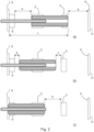
- Fig. 2 then illustrates the total length L, required for the design of Fig. 1 and indicating the space occupied by this design.
- Fig. 2 shows a schematic cross-section of the design of this conventional linear three-position disconnector switch, where a) shows the connected position, b) shows the disconnected position, and c) shows the earthed position.
- numeral 6 represents for example a wall of the switchgear, or in general any kind of surface with earth potential, and this can be linked to the earthing contact housing.
- Distance “a” is the distance between the earthing contact 1 and the first end of the piston 4 when the switch is in the connected position.
- Distance “e” is the distance between the other second end of the piston 4 and an earthed wall 6 of the switchgear.
- Distance “b” is the distance between the first end of the piston 4 and the earthing contact 1 when the switch is in the disconnected position
- distance "c” is the associated distance between the second end of the piston 4 and the power in contact 3.
- Distance “d” is the distance between the second end of the piston 4 and the power in contact 3 when the switch is in the earthed position.
- distances "b” and “c” can be of the same length, but actual distances might slightly vary due to other reasons.
- the distances "b” and “c” are selected in order that all required dielectric are fulfilled with respect to the given voltage levels.
- Distances "a” and “d” will be bigger than “b” and “c”, due to the physical location of the contacts 1, 2 and 3 and due to the rounded edges of the piston 4 needed for smooth sliding/centering into these contacts.
- the total length of the three-position disconnector switch is indicated as "L".
- the parts of the switch need to be spaced a certain distance “e” from other surrounding grounded parts 6, for example a grounded wall of a switchgear.
- this has a significant impact on total length "L” of the three-position disconnector switch. This is because in addition to distances “b” and “c” increase, also distances “a” and “b” will be thus increased, as well as the piston 4 itself then needs to be longer. It is to be noted that in general distance “a” is bigger than distance "b” and distance “d” is bigger than distance "c”.
- a disadvantage of the current three-posiiton switch described with respect to Figs. 1-2 is that a relatively long total length "L" is required to accommodate all contacts and to keep enough distance from all surrounded parts.
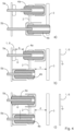
- Fig. 3 shows an example of a new three-position disconnector switch design, that addresses this disadvantage.
- a cross-section of the new length-optimized disconnector switch is shown, where a) shows the connected position, b) shows the disconnected position, and c) shows the earthed position.
- the three-position disconnector switch comprises an earthing contact 1, a power out contact 2, a power in contact 3, a first piston 4a, and a second piston 4b.
- the first piston is configured to make an electrical connection with the power out contact
- the second piston is configured to make an electrical connection with the power out contact and the power in contact.
- the first piston is configured to make an electrical connection with the power out contact and the second piston is configured to make an electrical connection with the power out contact.
- the first piston is configured to make an electrical connection with the earthing contact and with the power out contact and the second piston is configured to make an electrical connection with the power out contact.
- the three-position switch comprises: a first threaded rod 5a, and a second threaded rod 5b. Rotation of the first threaded rod is configured to engage with the first piston to move the first piston and rotation of the second threaded rod is configured to engage with the second piston to move the second piston.
- the three-position disconnector switch in the connected switch position is configured such that the first piston does not make an electrical connection with the power in contact.
- the three-position disconnector switch in the disconnected switch position is configured such that the first piston does not make an electrical connection with the power in contact.
- the three-position disconnector switch in the disconnected switch position is configured such that the second piston does not make an electrical connection with the earthing contact.
- the three-position disconnector switch in the earthed switch position is configured such that the second piston does not make an electrical connection with the earthing contact.
- a distance between a first end of the first piston and the power in contact is less than a distance between a second end of the first piston and the earthing contact.
- a distance between the first end of the first piston and the power in contact is less than a distance between the second end of the first piston and the earthing contact.
- the first end of the first piston is spaced from the power in contact by the same distance.
- the second end of the first piston is spaced from the earthing contact by the same distance.
- the distances a an b can be different, with the above relating only to a specific exemplar embodiment.
- the first end of the first piston can be spaced from the power in contact by different distances.
- the second end of the first piston can be spaced from the earthing contact by different distances.
- the three-position disconnector switch comprises a first insulator part.
- the first insulator part In the connected switch position, and the disconnected switch position, the first insulator part is located between the first end of the first piston and the power in contact.
- the first insulator part is located between the first end of the first piston and the power in contact.
- the first end of the first piston is at least partially located within the first insulator part.
- a distance between a first end of the second piston and the power in contact is greater than a distance between a second end of the second piston and the earthing contact or housing wall in electrical contact with the earthing contact.
- a distance between the first end of the second piston and the power in contact is greater than a distance between the second end of the second piston and the earthing contact or the housing wall in electrical contact with the earthing contact.
- the first end of the second piston is spaced from the power in contact by the same distance.
- the second end of the second piston in the disconnected switch position and the earthed switch position is spaced from the earthing contact or housing wall in electrical contact with the earthing contact by the same distance.
- the distances can d can be different, with the above relating only to a specific exemplar embodiment.
- the first end of the second piston can be spaced from the power in contact by different distances.
- the second end of the second piston can be spaced from the earthing contact or housing wall in electrical contact with the earthing contact by different distances.
- the three-position disconnector switch comprises a second insulator part.
- the second insulator part In the disconnected switch position, and the earthed switch position, the second insulator part is located between the second end of the second piston and the earthing contact or the housing wall in electrical contact with the earthing contact.
- the second insulator part in the connected switch position is located between the second end of the second piston and the earthing contact or the housing wall in electrical contact with the earthing contact.
- the second end of the second piston is at least partially located within the second insulator part.
- the first piston is configured to move along a first axis and the second piston is configured to move along a second axis, where the first axis is parallel to the second axis and the first axis is spaced laterally to the second axis.
- these two parts can be located in a horizontal or vertical orientation, and indeed there can be something between the two.
- One or more of the new three-position disconnector switches as described with respect to fig. 3 can be utilized in a low voltage or medium voltage switchgear or control gear.
- the new three-position disconnector design provides an improvement/reduction in the length of the switch, making the switch suitable for areas with reduced available space in a longitudinal direction. This is achieved by locating parts of the switch in parallel.
- Cap 7 helps to minimize the distance of the piston 4a to the power incoming contact 3 and cap 8 helps to minimize the distance of the piston 4b to earthed surrounded part 6.
- distance "b” can be the same as distance "a”
- distance "c” can be the same as distance "d”.
- Distance "a” is the distance between the earthing contact 1 and the second end of the first piston 4a when the switch is in the connected position
- distance "b” is the associated position when the switch is in the disconnected position
- Distance "c” is the distance between the first end of the second piston 4b and the power in contact 3 when the switch is in a disconnected position
- distance "d” is the associated distance when the switch is in the earthed position.
- the insulating caps 7 and 8 could be fixed in certain positions and pistons 4a and 4b can move in and out respectively, as described with respect to and shown in Fig. 3 , but there could also be a solution where insulating caps are fixed to the pistons and move together with them.
- An example of such a configuration is described with respect to and shown in Fig. 4 , which shows a cross section of the new length optimized disconnector with insulating parts attached to the pistons, with a) the connected position, b) the disconnected position and c) the earthed position.
- the new configuration fulfills the functionality of a three-position disconnector switch, but it can be also be considered as a parallel configuration of two two-position disconnector switches and used independently.
- the switches When used as a three-position disconnector switch, sequential movements of the piston 4a and 4b is provided, and the drives of each part linked to the motor driven threads 5a and 5b are aligned in a way that movements in the desired direction are allowed, and movement in the other direction is blocked in order to prevent for example direct earthing of the power incoming contact.
- the drives of the disconnectors can be motorized, electromagnetically driven or even manual, with proper interlocking of both moving parts.
- the switch can be configured such that piston 4a of the upper part cannot move to earth position unless the piston 4b of lower part is in a disconnected position.
- Insulating cap 7 can move along with the piston 4a or can be fixed to the power incoming contact 3 or could be kept a certain distance in order to avoid dielectric issues, depending on the chosen material, its thickness and dielectric strength.
- Insulating cap 8 can move along with the piston 4b or can be fixed directly to the wall 6, since the wall is in contact with earth.
- Threaded rod 5b can be made of some insulating material, and properly assembled within the cap 8 in order to avoid gap and dielectric discharges penetrating along the threaded rod further to the drive.
- the rod 5b can for example be made of several parts, ensuring proper insulation and no gap within the cap 8.
Landscapes
- Engineering & Computer Science (AREA)
- Power Engineering (AREA)
- Physics & Mathematics (AREA)
- Electromagnetism (AREA)
- Gas-Insulated Switchgears (AREA)
Claims (14)
- Commutateur de déconnexion à trois positions, comprenant :un contact de mise à la terre (1) ;- un contact de sortie de puissance (2) ;- un contact d'entrée de puissance (3) ;- un premier piston (4a) ; et- un deuxième piston (4b) ;dans lequel, dans une position de commutation connectée :
le premier piston (4a) est configuré pour établir une connexion électrique avec le contact de sortie de puissance (2) et le deuxième piston (4b) est configuré pour établir une connexion électrique avec le contact de sortie de puissance (2) et le contact d'entrée de puissance (3), et dans lequel la position de commutation connectée, une distance entre une première extrémité du premier piston (4a) et le contact d'entrée de puissance (3) est inférieure à une distance entre une deuxième extrémité du premier piston (4a) et le contact de mise à la terre (1) ;dans lequel, dans une position de commutation déconnectée :
le premier piston (4a) est configuré pour établir une connexion électrique avec le contact de sortie de puissance (2) et le deuxième piston (4b) est configuré pour établir une connexion électrique avec le contact de sortie de puissance (2) ;dans lequel, dans une position de commutation mise à la terre :
le premier piston (4a) est configuré pour établir une connexion électrique avec le contact de mise à la terre (1) et avec le contact de sortie de puissance (2) et le deuxième piston (4b) est configuré pour établir une connexion électrique avec le contact de sortie de puissance (2). - Commutateur de déconnexion à trois positions selon la revendication 1, dans lequel, dans la position de commutation connectée, le commutateur de déconnexion à trois positions est configuré de telle sorte que le premier piston n'établisse pas de connexion électrique avec le contact d'entrée de puissance.
- Commutateur de déconnexion à trois positions selon l'une quelconque des revendications 1 à 2, dans lequel, dans la position de commutation déconnectée le commutateur de déconnexion à trois positions est configuré de telle sorte que le premier piston n'établisse pas de connexion électrique avec le contact d'entrée de puissance.
- Commutateur de déconnexion à trois positions selon l'une quelconque des revendications 1 à 3, dans lequel, dans la position de commutation déconnectée le commutateur de déconnexion à trois positions est configuré de telle sorte que le deuxième piston n'établisse pas de connexion électrique avec le contact de mise à la terre.
- Commutateur de déconnexion à trois positions selon l'une quelconque des revendications 1 à 4, dans lequel, dans la position de commutation mise à la terre le commutateur de déconnexion à trois positions est configuré de telle sorte que le deuxième piston n'établisse pas de connexion électrique avec le contact de mise à la terre.
- Commutateur de déconnexion à trois positions selon l'une quelconque des revendications 1 à 5, dans lequel, dans la position de commutation déconnectée une distance entre la première extrémité du premier piston et le contact de puissance d'entrée est inférieure à une distance entre la deuxième extrémité du premier piston et le contact de mise à la terre.
- Commutateur de déconnexion à trois positions selon l'une quelconque des revendications 1 à 6, dans lequel le commutateur de déconnexion à trois positions comprend une première partie isolante, dans lequel dans la position de commutation connectée et la position de commutation déconnectée la première partie isolante est située entre la première extrémité du premier piston et le contact de puissance d'entrée.
- Commutateur de déconnexion à trois positions selon la revendication 7, dans lequel, dans la position de commutation connectée et la position de commutation déconnectée la première extrémité du premier piston est au moins partiellement située à l'intérieur de la première partie isolante.
- Commutateur de déconnexion à trois positions selon l'une quelconque des revendications 1 à 8, dans lequel, dans la position de commutation déconnectée une distance entre une première extrémité du deuxième piston et le contact d'entrée de puissance est supérieure à une distance entre une deuxième extrémité du deuxième piston et le contact de mise à la terre ou la paroi de boîtier en contact électrique avec le contact de mise à la terre.
- Commutateur de déconnexion à trois positions selon la revendication 9, dans lequel, dans la position de commutation mise à la terre une distance entre la première extrémité du deuxième piston et le contact d'entrée de puissance est supérieure à une distance entre la deuxième extrémité du deuxième piston et le contact de mise à la terre ou la paroi de boîtier en contact électrique avec le contact de mise à la terre.
- Commutateur de déconnexion à trois positions selon l'une quelconque des revendications 9 à 10, dans lequel commutateur de déconnexion à trois positions comprend une deuxième partie isolante, dans la position de commutation déconnectée et la position de commutation mise à la terre, la deuxième partie isolante est située entre la deuxième extrémité du deuxième piston et le contact de mise à la terre ou la paroi de boîtier en contact électrique avec le contact de mise à la terre.
- Commutateur de déconnexion à trois positions selon la revendication 11, dans lequel, dans la position de commutation déconnectée et la position de commutation mise à la terre la deuxième extrémité du deuxième piston est au moins partiellement située à l'intérieur de la deuxième partie isolante.
- Commutateur de déconnexion à trois positions selon l'une quelconque des revendications 1 à 12, dans lequel le premier piston est configuré pour se déplacer le long d'un premier axe et le deuxième piston est configuré pour se déplacer le long d'un deuxième axe, où le premier axe est parallèle au deuxième axe et le premier axe est espacé latéralement ou au moins partiellement au-dessus du deuxième axe.
- Appareillage de commutation ou de commande basse tension ou moyenne tension comprenant un ou plusieurs commutateurs de déconnexion à trois positions selon l'une quelconque des revendications 1 à 13.
Priority Applications (3)
| Application Number | Priority Date | Filing Date | Title |
|---|---|---|---|
| EP19215336.9A EP3836182B1 (fr) | 2019-12-11 | 2019-12-11 | Commutateur de déconnexion à trois positions |
| US17/110,332 US11342140B2 (en) | 2019-12-11 | 2020-12-03 | Three-position disconnector switch |
| CN202011461960.XA CN112951643B (zh) | 2019-12-11 | 2020-12-10 | 三位置隔离开关 |
Applications Claiming Priority (1)
| Application Number | Priority Date | Filing Date | Title |
|---|---|---|---|
| EP19215336.9A EP3836182B1 (fr) | 2019-12-11 | 2019-12-11 | Commutateur de déconnexion à trois positions |
Publications (2)
| Publication Number | Publication Date |
|---|---|
| EP3836182A1 EP3836182A1 (fr) | 2021-06-16 |
| EP3836182B1 true EP3836182B1 (fr) | 2023-03-08 |
Family
ID=68886898
Family Applications (1)
| Application Number | Title | Priority Date | Filing Date |
|---|---|---|---|
| EP19215336.9A Active EP3836182B1 (fr) | 2019-12-11 | 2019-12-11 | Commutateur de déconnexion à trois positions |
Country Status (3)
| Country | Link |
|---|---|
| US (1) | US11342140B2 (fr) |
| EP (1) | EP3836182B1 (fr) |
| CN (1) | CN112951643B (fr) |
Families Citing this family (5)
| Publication number | Priority date | Publication date | Assignee | Title |
|---|---|---|---|---|
| EP3671986B1 (fr) * | 2018-12-19 | 2025-05-14 | ABB Schweiz AG | Appareillage de commutation |
| EP4089698B1 (fr) * | 2021-05-14 | 2025-01-22 | ABB Schweiz AG | Commutateur de déconnexion à trois positions |
| CN113921324A (zh) * | 2021-10-20 | 2022-01-11 | 广东电网有限责任公司江门供电局 | 一种10kV隔离刀闸电动操作装置 |
| CN217306386U (zh) * | 2022-03-02 | 2022-08-26 | 西门子能源国际公司 | 隔离开关 |
| EP4718491A1 (fr) * | 2024-09-30 | 2026-04-01 | Hitachi Energy Ltd | Sectionneur pour disjoncteur haute tension à courant continu et haute tension à courant continu |
Family Cites Families (23)
| Publication number | Priority date | Publication date | Assignee | Title |
|---|---|---|---|---|
| AU553021B2 (en) * | 1981-02-19 | 1986-07-03 | Burndy Corporation | Electrical harness |
| JP3369228B2 (ja) * | 1992-11-12 | 2003-01-20 | 株式会社東芝 | 高速再閉路接地開閉器 |
| DE19625128A1 (de) * | 1996-06-12 | 1997-12-18 | Fachhochschule Fuer Technik Un | Vakuumschaltkammer |
| FR2788165B1 (fr) * | 1998-12-30 | 2001-02-02 | Pyroalliance | Contacteur electrique a fonctionnement pyrotechnique |
| FR2805406B1 (fr) * | 2000-02-23 | 2002-08-23 | Alstom | Commutateur electrique a trois positions avec un element de commutation mobile axialement |
| JP2002124167A (ja) * | 2000-10-17 | 2002-04-26 | Mitsubishi Electric Corp | パッファ形ガス遮断器 |
| AU2005253220B2 (en) * | 2004-06-09 | 2008-10-23 | Abb Technology Ag | Gas-Insulated Switchgear Assembly |
| US7186942B1 (en) * | 2006-02-23 | 2007-03-06 | Eaton Corporation | Three-position vacuum interrupter disconnect switch providing current interruption, disconnection and grounding |
| DE102006053376A1 (de) * | 2006-11-10 | 2008-05-15 | Abb Technology Ag | Elektrische Hochspannugnsanlage |
| CN201229884Y (zh) * | 2008-07-02 | 2009-04-29 | 中国西电电气股份有限公司 | 一种快速接地开关 |
| DE102009030610A1 (de) * | 2009-06-23 | 2010-12-30 | Siemens Aktiengesellschaft | Hochspannungsanordnung |
| JP5471925B2 (ja) * | 2010-07-16 | 2014-04-16 | 株式会社日立製作所 | 接地開閉器付断路器 |
| JP5211147B2 (ja) * | 2010-12-20 | 2013-06-12 | 株式会社日立製作所 | スイッチギヤ |
| EP2715758B1 (fr) * | 2011-05-27 | 2016-06-29 | ABB Technology AG | Appareil de mise à la terre |
| DE102014104541B4 (de) * | 2014-03-31 | 2025-11-13 | Schneider Electric Industries Sas | Schaltfeld |
| CN203871259U (zh) * | 2014-04-23 | 2014-10-08 | 苏金发 | 充气式三工位高压开关 |
| CN104201041B (zh) * | 2014-08-15 | 2015-10-21 | 浙江道笃智能开关有限公司 | 组合固封极柱及其工作原理 |
| CN204102789U (zh) * | 2014-09-12 | 2015-01-14 | 宁波耀华电气科技有限责任公司 | 活塞式隔离开关 |
| EP3121831B1 (fr) * | 2015-07-23 | 2017-09-13 | General Electric Technology GmbH | Agencement de commutateur de mise à la terre électrique de sous-station isolée par gaz |
| WO2017141060A1 (fr) * | 2016-02-18 | 2017-08-24 | Koncar - Elektricni Visokonaponski Aparati D.D. | Module de commutation combiné de déconnexion et de mise à la terre pour un appareillage de commutation à isolation gazeuse |
| EP3336870B1 (fr) * | 2016-12-14 | 2021-11-03 | General Electric Technology GmbH | Gis à commutateur de déconnexion et raccordement à la terre |
| KR101897736B1 (ko) * | 2017-01-06 | 2018-09-12 | 엘에스산전 주식회사 | 가스절연 개폐장치용 3웨이 단로기와 접지개폐기 |
| CN108010789A (zh) * | 2017-12-13 | 2018-05-08 | 上海天灵开关厂有限公司 | 一种带有散热结构的大电流直动式三工位开关 |
-
2019
- 2019-12-11 EP EP19215336.9A patent/EP3836182B1/fr active Active
-
2020
- 2020-12-03 US US17/110,332 patent/US11342140B2/en active Active
- 2020-12-10 CN CN202011461960.XA patent/CN112951643B/zh active Active
Also Published As
| Publication number | Publication date |
|---|---|
| US20210183597A1 (en) | 2021-06-17 |
| US11342140B2 (en) | 2022-05-24 |
| EP3836182A1 (fr) | 2021-06-16 |
| CN112951643A (zh) | 2021-06-11 |
| CN112951643B (zh) | 2024-10-29 |
Similar Documents
| Publication | Publication Date | Title |
|---|---|---|
| US11342140B2 (en) | Three-position disconnector switch | |
| EP2546850B1 (fr) | Appareil de commutation et procédé de fonctionnement d'un appareil de commutation | |
| US6559403B2 (en) | Three-position electrical switch having a switching element that is movable in axial translation | |
| US8487203B2 (en) | Disconnecting switch with earthing switch | |
| CN1197214C (zh) | 气体绝缘开关装置 | |
| KR19980018452A (ko) | 금속 밀폐 가스 절연 고압 스위치 기어를 위한 분리/접지 스위치 | |
| US20100089875A1 (en) | High and medium voltage switch apparatus with two interrupters, having common means for actuating the movable contacts of the interrupters | |
| JP4388032B2 (ja) | 固体絶縁断路器 | |
| EP3407367B1 (fr) | Sectionneur triphasé et interrupteur de mise à terre pour un appareil de commutation à isolation gazeuse | |
| KR101212783B1 (ko) | 가스절연기기용 3-way 스위치 | |
| EP3336870B1 (fr) | Gis à commutateur de déconnexion et raccordement à la terre | |
| CN1253908C (zh) | 带有传动装置的混合断路器 | |
| KR100771673B1 (ko) | 가스 절연 개폐장치 | |
| RU2516446C2 (ru) | Электрическое устройство переключения, содержащее два прерывателя, таких как шинный разъединитель и заземляющий разъединитель, и содержащее общее исполнительное устройство для подвижных контактов прерывателей | |
| EP2884518B1 (fr) | Appareil de commutation pour systèmes d'alimentation électrique | |
| CN102959668B (zh) | 紧凑型接地隔离器 | |
| US10832881B2 (en) | Medium voltage switching apparatus | |
| KR200321221Y1 (ko) | 가스절연 개폐장치용 단로기/접지개폐기 | |
| US5902979A (en) | Gas insulation type load break system | |
| WO2017207742A1 (fr) | Dispositif de commutation à double boîtier conducteur | |
| US4110578A (en) | Circuit breaker | |
| KR200291485Y1 (ko) | 가스절연 3 단 개폐장치 | |
| EP2360798B1 (fr) | Dispositif de commutation impérméable au gaz | |
| US11651917B2 (en) | Electrode driving device for gas insulated switchgear | |
| KR101390499B1 (ko) | 가스절연 개폐장치용 단로기 및 접지개폐기 |
Legal Events
| Date | Code | Title | Description |
|---|---|---|---|
| PUAI | Public reference made under article 153(3) epc to a published international application that has entered the european phase |
Free format text: ORIGINAL CODE: 0009012 |
|
| STAA | Information on the status of an ep patent application or granted ep patent |
Free format text: STATUS: THE APPLICATION HAS BEEN PUBLISHED |
|
| AK | Designated contracting states |
Kind code of ref document: A1 Designated state(s): AL AT BE BG CH CY CZ DE DK EE ES FI FR GB GR HR HU IE IS IT LI LT LU LV MC MK MT NL NO PL PT RO RS SE SI SK SM TR |
|
| STAA | Information on the status of an ep patent application or granted ep patent |
Free format text: STATUS: REQUEST FOR EXAMINATION WAS MADE |
|
| 17P | Request for examination filed |
Effective date: 20211207 |
|
| RBV | Designated contracting states (corrected) |
Designated state(s): AL AT BE BG CH CY CZ DE DK EE ES FI FR GB GR HR HU IE IS IT LI LT LU LV MC MK MT NL NO PL PT RO RS SE SI SK SM TR |
|
| GRAP | Despatch of communication of intention to grant a patent |
Free format text: ORIGINAL CODE: EPIDOSNIGR1 |
|
| STAA | Information on the status of an ep patent application or granted ep patent |
Free format text: STATUS: GRANT OF PATENT IS INTENDED |
|
| INTG | Intention to grant announced |
Effective date: 20220927 |
|
| GRAS | Grant fee paid |
Free format text: ORIGINAL CODE: EPIDOSNIGR3 |
|
| GRAA | (expected) grant |
Free format text: ORIGINAL CODE: 0009210 |
|
| STAA | Information on the status of an ep patent application or granted ep patent |
Free format text: STATUS: THE PATENT HAS BEEN GRANTED |
|
| AK | Designated contracting states |
Kind code of ref document: B1 Designated state(s): AL AT BE BG CH CY CZ DE DK EE ES FI FR GB GR HR HU IE IS IT LI LT LU LV MC MK MT NL NO PL PT RO RS SE SI SK SM TR |
|
| RAP3 | Party data changed (applicant data changed or rights of an application transferred) |
Owner name: ABB SCHWEIZ AG |
|
| REG | Reference to a national code |
Ref country code: CH Ref legal event code: EP Ref country code: AT Ref legal event code: REF Ref document number: 1553147 Country of ref document: AT Kind code of ref document: T Effective date: 20230315 |
|
| REG | Reference to a national code |
Ref country code: DE Ref legal event code: R096 Ref document number: 602019026106 Country of ref document: DE |
|
| REG | Reference to a national code |
Ref country code: IE Ref legal event code: FG4D |
|
| REG | Reference to a national code |
Ref country code: LT Ref legal event code: MG9D |
|
| REG | Reference to a national code |
Ref country code: NL Ref legal event code: MP Effective date: 20230308 |
|
| PG25 | Lapsed in a contracting state [announced via postgrant information from national office to epo] |
Ref country code: RS Free format text: LAPSE BECAUSE OF FAILURE TO SUBMIT A TRANSLATION OF THE DESCRIPTION OR TO PAY THE FEE WITHIN THE PRESCRIBED TIME-LIMIT Effective date: 20230308 Ref country code: NO Free format text: LAPSE BECAUSE OF FAILURE TO SUBMIT A TRANSLATION OF THE DESCRIPTION OR TO PAY THE FEE WITHIN THE PRESCRIBED TIME-LIMIT Effective date: 20230608 Ref country code: LV Free format text: LAPSE BECAUSE OF FAILURE TO SUBMIT A TRANSLATION OF THE DESCRIPTION OR TO PAY THE FEE WITHIN THE PRESCRIBED TIME-LIMIT Effective date: 20230308 Ref country code: LT Free format text: LAPSE BECAUSE OF FAILURE TO SUBMIT A TRANSLATION OF THE DESCRIPTION OR TO PAY THE FEE WITHIN THE PRESCRIBED TIME-LIMIT Effective date: 20230308 Ref country code: HR Free format text: LAPSE BECAUSE OF FAILURE TO SUBMIT A TRANSLATION OF THE DESCRIPTION OR TO PAY THE FEE WITHIN THE PRESCRIBED TIME-LIMIT Effective date: 20230308 Ref country code: ES Free format text: LAPSE BECAUSE OF FAILURE TO SUBMIT A TRANSLATION OF THE DESCRIPTION OR TO PAY THE FEE WITHIN THE PRESCRIBED TIME-LIMIT Effective date: 20230308 |
|
| REG | Reference to a national code |
Ref country code: AT Ref legal event code: MK05 Ref document number: 1553147 Country of ref document: AT Kind code of ref document: T Effective date: 20230308 |
|
| PG25 | Lapsed in a contracting state [announced via postgrant information from national office to epo] |
Ref country code: SE Free format text: LAPSE BECAUSE OF FAILURE TO SUBMIT A TRANSLATION OF THE DESCRIPTION OR TO PAY THE FEE WITHIN THE PRESCRIBED TIME-LIMIT Effective date: 20230308 Ref country code: NL Free format text: LAPSE BECAUSE OF FAILURE TO SUBMIT A TRANSLATION OF THE DESCRIPTION OR TO PAY THE FEE WITHIN THE PRESCRIBED TIME-LIMIT Effective date: 20230308 Ref country code: GR Free format text: LAPSE BECAUSE OF FAILURE TO SUBMIT A TRANSLATION OF THE DESCRIPTION OR TO PAY THE FEE WITHIN THE PRESCRIBED TIME-LIMIT Effective date: 20230609 Ref country code: FI Free format text: LAPSE BECAUSE OF FAILURE TO SUBMIT A TRANSLATION OF THE DESCRIPTION OR TO PAY THE FEE WITHIN THE PRESCRIBED TIME-LIMIT Effective date: 20230308 |
|
| PG25 | Lapsed in a contracting state [announced via postgrant information from national office to epo] |
Ref country code: SM Free format text: LAPSE BECAUSE OF FAILURE TO SUBMIT A TRANSLATION OF THE DESCRIPTION OR TO PAY THE FEE WITHIN THE PRESCRIBED TIME-LIMIT Effective date: 20230308 Ref country code: RO Free format text: LAPSE BECAUSE OF FAILURE TO SUBMIT A TRANSLATION OF THE DESCRIPTION OR TO PAY THE FEE WITHIN THE PRESCRIBED TIME-LIMIT Effective date: 20230308 Ref country code: PT Free format text: LAPSE BECAUSE OF FAILURE TO SUBMIT A TRANSLATION OF THE DESCRIPTION OR TO PAY THE FEE WITHIN THE PRESCRIBED TIME-LIMIT Effective date: 20230710 Ref country code: EE Free format text: LAPSE BECAUSE OF FAILURE TO SUBMIT A TRANSLATION OF THE DESCRIPTION OR TO PAY THE FEE WITHIN THE PRESCRIBED TIME-LIMIT Effective date: 20230308 Ref country code: CZ Free format text: LAPSE BECAUSE OF FAILURE TO SUBMIT A TRANSLATION OF THE DESCRIPTION OR TO PAY THE FEE WITHIN THE PRESCRIBED TIME-LIMIT Effective date: 20230308 Ref country code: AT Free format text: LAPSE BECAUSE OF FAILURE TO SUBMIT A TRANSLATION OF THE DESCRIPTION OR TO PAY THE FEE WITHIN THE PRESCRIBED TIME-LIMIT Effective date: 20230308 |
|
| PG25 | Lapsed in a contracting state [announced via postgrant information from national office to epo] |
Ref country code: SK Free format text: LAPSE BECAUSE OF FAILURE TO SUBMIT A TRANSLATION OF THE DESCRIPTION OR TO PAY THE FEE WITHIN THE PRESCRIBED TIME-LIMIT Effective date: 20230308 Ref country code: PL Free format text: LAPSE BECAUSE OF FAILURE TO SUBMIT A TRANSLATION OF THE DESCRIPTION OR TO PAY THE FEE WITHIN THE PRESCRIBED TIME-LIMIT Effective date: 20230308 Ref country code: IS Free format text: LAPSE BECAUSE OF FAILURE TO SUBMIT A TRANSLATION OF THE DESCRIPTION OR TO PAY THE FEE WITHIN THE PRESCRIBED TIME-LIMIT Effective date: 20230708 |
|
| REG | Reference to a national code |
Ref country code: DE Ref legal event code: R097 Ref document number: 602019026106 Country of ref document: DE |
|
| PLBE | No opposition filed within time limit |
Free format text: ORIGINAL CODE: 0009261 |
|
| STAA | Information on the status of an ep patent application or granted ep patent |
Free format text: STATUS: NO OPPOSITION FILED WITHIN TIME LIMIT |
|
| PG25 | Lapsed in a contracting state [announced via postgrant information from national office to epo] |
Ref country code: SI Free format text: LAPSE BECAUSE OF FAILURE TO SUBMIT A TRANSLATION OF THE DESCRIPTION OR TO PAY THE FEE WITHIN THE PRESCRIBED TIME-LIMIT Effective date: 20230308 Ref country code: DK Free format text: LAPSE BECAUSE OF FAILURE TO SUBMIT A TRANSLATION OF THE DESCRIPTION OR TO PAY THE FEE WITHIN THE PRESCRIBED TIME-LIMIT Effective date: 20230308 |
|
| 26N | No opposition filed |
Effective date: 20231211 |
|
| REG | Reference to a national code |
Ref country code: CH Ref legal event code: PL |
|
| PG25 | Lapsed in a contracting state [announced via postgrant information from national office to epo] |
Ref country code: LU Free format text: LAPSE BECAUSE OF NON-PAYMENT OF DUE FEES Effective date: 20231211 |
|
| PG25 | Lapsed in a contracting state [announced via postgrant information from national office to epo] |
Ref country code: MC Free format text: LAPSE BECAUSE OF FAILURE TO SUBMIT A TRANSLATION OF THE DESCRIPTION OR TO PAY THE FEE WITHIN THE PRESCRIBED TIME-LIMIT Effective date: 20230308 |
|
| GBPC | Gb: european patent ceased through non-payment of renewal fee |
Effective date: 20231211 |
|
| REG | Reference to a national code |
Ref country code: BE Ref legal event code: MM Effective date: 20231231 |
|
| PG25 | Lapsed in a contracting state [announced via postgrant information from national office to epo] |
Ref country code: MC Free format text: LAPSE BECAUSE OF FAILURE TO SUBMIT A TRANSLATION OF THE DESCRIPTION OR TO PAY THE FEE WITHIN THE PRESCRIBED TIME-LIMIT Effective date: 20230308 Ref country code: LU Free format text: LAPSE BECAUSE OF NON-PAYMENT OF DUE FEES Effective date: 20231211 |
|
| REG | Reference to a national code |
Ref country code: IE Ref legal event code: MM4A |
|
| PG25 | Lapsed in a contracting state [announced via postgrant information from national office to epo] |
Ref country code: IE Free format text: LAPSE BECAUSE OF NON-PAYMENT OF DUE FEES Effective date: 20231211 |
|
| PG25 | Lapsed in a contracting state [announced via postgrant information from national office to epo] |
Ref country code: GB Free format text: LAPSE BECAUSE OF NON-PAYMENT OF DUE FEES Effective date: 20231211 |
|
| PG25 | Lapsed in a contracting state [announced via postgrant information from national office to epo] |
Ref country code: BE Free format text: LAPSE BECAUSE OF NON-PAYMENT OF DUE FEES Effective date: 20231231 |
|
| PG25 | Lapsed in a contracting state [announced via postgrant information from national office to epo] |
Ref country code: CH Free format text: LAPSE BECAUSE OF NON-PAYMENT OF DUE FEES Effective date: 20231231 |
|
| PG25 | Lapsed in a contracting state [announced via postgrant information from national office to epo] |
Ref country code: IE Free format text: LAPSE BECAUSE OF NON-PAYMENT OF DUE FEES Effective date: 20231211 Ref country code: GB Free format text: LAPSE BECAUSE OF NON-PAYMENT OF DUE FEES Effective date: 20231211 Ref country code: CH Free format text: LAPSE BECAUSE OF NON-PAYMENT OF DUE FEES Effective date: 20231231 Ref country code: BE Free format text: LAPSE BECAUSE OF NON-PAYMENT OF DUE FEES Effective date: 20231231 |
|
| PG25 | Lapsed in a contracting state [announced via postgrant information from national office to epo] |
Ref country code: BG Free format text: LAPSE BECAUSE OF FAILURE TO SUBMIT A TRANSLATION OF THE DESCRIPTION OR TO PAY THE FEE WITHIN THE PRESCRIBED TIME-LIMIT Effective date: 20230308 |
|
| PG25 | Lapsed in a contracting state [announced via postgrant information from national office to epo] |
Ref country code: BG Free format text: LAPSE BECAUSE OF FAILURE TO SUBMIT A TRANSLATION OF THE DESCRIPTION OR TO PAY THE FEE WITHIN THE PRESCRIBED TIME-LIMIT Effective date: 20230308 |
|
| PG25 | Lapsed in a contracting state [announced via postgrant information from national office to epo] |
Ref country code: CY Free format text: LAPSE BECAUSE OF FAILURE TO SUBMIT A TRANSLATION OF THE DESCRIPTION OR TO PAY THE FEE WITHIN THE PRESCRIBED TIME-LIMIT; INVALID AB INITIO Effective date: 20191211 |
|
| PG25 | Lapsed in a contracting state [announced via postgrant information from national office to epo] |
Ref country code: HU Free format text: LAPSE BECAUSE OF FAILURE TO SUBMIT A TRANSLATION OF THE DESCRIPTION OR TO PAY THE FEE WITHIN THE PRESCRIBED TIME-LIMIT; INVALID AB INITIO Effective date: 20191211 |
|
| PG25 | Lapsed in a contracting state [announced via postgrant information from national office to epo] |
Ref country code: TR Free format text: LAPSE BECAUSE OF FAILURE TO SUBMIT A TRANSLATION OF THE DESCRIPTION OR TO PAY THE FEE WITHIN THE PRESCRIBED TIME-LIMIT Effective date: 20230308 |
|
| PGFP | Annual fee paid to national office [announced via postgrant information from national office to epo] |
Ref country code: DE Payment date: 20251211 Year of fee payment: 7 |
|
| PGFP | Annual fee paid to national office [announced via postgrant information from national office to epo] |
Ref country code: IT Payment date: 20251223 Year of fee payment: 7 |
|
| PGFP | Annual fee paid to national office [announced via postgrant information from national office to epo] |
Ref country code: FR Payment date: 20251229 Year of fee payment: 7 |