EP3836294B1 - Batteriemodul mit verbesserter wärmeableitung, batteriepack mit batteriemodul und fahrzeug mit diesem batteriepack - Google Patents
Batteriemodul mit verbesserter wärmeableitung, batteriepack mit batteriemodul und fahrzeug mit diesem batteriepack Download PDFInfo
- Publication number
- EP3836294B1 EP3836294B1 EP19891450.9A EP19891450A EP3836294B1 EP 3836294 B1 EP3836294 B1 EP 3836294B1 EP 19891450 A EP19891450 A EP 19891450A EP 3836294 B1 EP3836294 B1 EP 3836294B1
- Authority
- EP
- European Patent Office
- Prior art keywords
- battery
- battery module
- constant voltage
- thermoelectric device
- battery cell
- Prior art date
- Legal status (The legal status is an assumption and is not a legal conclusion. Google has not performed a legal analysis and makes no representation as to the accuracy of the status listed.)
- Active
Links
Images





Classifications
-
- G—PHYSICS
- G01—MEASURING; TESTING
- G01R—MEASURING ELECTRIC VARIABLES; MEASURING MAGNETIC VARIABLES
- G01R31/00—Arrangements for testing electric properties; Arrangements for locating electric faults; Arrangements for electrical testing characterised by what is being tested not provided for elsewhere
- G01R31/36—Arrangements for testing, measuring or monitoring the electrical condition of accumulators or electric batteries, e.g. capacity or state of charge [SoC]
- G01R31/382—Arrangements for monitoring battery or accumulator variables, e.g. SoC
- G01R31/3835—Arrangements for monitoring battery or accumulator variables, e.g. SoC involving only voltage measurements
-
- H—ELECTRICITY
- H01—ELECTRIC ELEMENTS
- H01M—PROCESSES OR MEANS, e.g. BATTERIES, FOR THE DIRECT CONVERSION OF CHEMICAL ENERGY INTO ELECTRICAL ENERGY
- H01M10/00—Secondary cells; Manufacture thereof
- H01M10/42—Methods or arrangements for servicing or maintenance of secondary cells or secondary half-cells
- H01M10/48—Accumulators combined with arrangements for measuring, testing or indicating the condition of cells, e.g. the level or density of the electrolyte
-
- H—ELECTRICITY
- H01—ELECTRIC ELEMENTS
- H01M—PROCESSES OR MEANS, e.g. BATTERIES, FOR THE DIRECT CONVERSION OF CHEMICAL ENERGY INTO ELECTRICAL ENERGY
- H01M10/00—Secondary cells; Manufacture thereof
- H01M10/60—Heating or cooling; Temperature control
- H01M10/61—Types of temperature control
- H01M10/613—Cooling or keeping cold
-
- H—ELECTRICITY
- H01—ELECTRIC ELEMENTS
- H01M—PROCESSES OR MEANS, e.g. BATTERIES, FOR THE DIRECT CONVERSION OF CHEMICAL ENERGY INTO ELECTRICAL ENERGY
- H01M10/00—Secondary cells; Manufacture thereof
- H01M10/60—Heating or cooling; Temperature control
- H01M10/62—Heating or cooling; Temperature control specially adapted for specific applications
- H01M10/625—Vehicles
-
- H—ELECTRICITY
- H01—ELECTRIC ELEMENTS
- H01M—PROCESSES OR MEANS, e.g. BATTERIES, FOR THE DIRECT CONVERSION OF CHEMICAL ENERGY INTO ELECTRICAL ENERGY
- H01M10/00—Secondary cells; Manufacture thereof
- H01M10/60—Heating or cooling; Temperature control
- H01M10/64—Heating or cooling; Temperature control characterised by the shape of the cells
- H01M10/647—Prismatic or flat cells, e.g. pouch cells
-
- H—ELECTRICITY
- H01—ELECTRIC ELEMENTS
- H01M—PROCESSES OR MEANS, e.g. BATTERIES, FOR THE DIRECT CONVERSION OF CHEMICAL ENERGY INTO ELECTRICAL ENERGY
- H01M10/00—Secondary cells; Manufacture thereof
- H01M10/60—Heating or cooling; Temperature control
- H01M10/65—Means for temperature control structurally associated with the cells
- H01M10/655—Solid structures for heat exchange or heat conduction
- H01M10/6551—Surfaces specially adapted for heat dissipation or radiation, e.g. fins or coatings
-
- H—ELECTRICITY
- H01—ELECTRIC ELEMENTS
- H01M—PROCESSES OR MEANS, e.g. BATTERIES, FOR THE DIRECT CONVERSION OF CHEMICAL ENERGY INTO ELECTRICAL ENERGY
- H01M10/00—Secondary cells; Manufacture thereof
- H01M10/60—Heating or cooling; Temperature control
- H01M10/65—Means for temperature control structurally associated with the cells
- H01M10/655—Solid structures for heat exchange or heat conduction
- H01M10/6553—Terminals or leads
-
- H—ELECTRICITY
- H01—ELECTRIC ELEMENTS
- H01M—PROCESSES OR MEANS, e.g. BATTERIES, FOR THE DIRECT CONVERSION OF CHEMICAL ENERGY INTO ELECTRICAL ENERGY
- H01M10/00—Secondary cells; Manufacture thereof
- H01M10/60—Heating or cooling; Temperature control
- H01M10/65—Means for temperature control structurally associated with the cells
- H01M10/655—Solid structures for heat exchange or heat conduction
- H01M10/6554—Rods or plates
-
- H—ELECTRICITY
- H01—ELECTRIC ELEMENTS
- H01M—PROCESSES OR MEANS, e.g. BATTERIES, FOR THE DIRECT CONVERSION OF CHEMICAL ENERGY INTO ELECTRICAL ENERGY
- H01M10/00—Secondary cells; Manufacture thereof
- H01M10/60—Heating or cooling; Temperature control
- H01M10/65—Means for temperature control structurally associated with the cells
- H01M10/657—Means for temperature control structurally associated with the cells by electric or electromagnetic means
- H01M10/6572—Peltier elements or thermoelectric devices
-
- H—ELECTRICITY
- H01—ELECTRIC ELEMENTS
- H01M—PROCESSES OR MEANS, e.g. BATTERIES, FOR THE DIRECT CONVERSION OF CHEMICAL ENERGY INTO ELECTRICAL ENERGY
- H01M50/00—Constructional details or processes of manufacture of the non-active parts of electrochemical cells other than fuel cells, e.g. hybrid cells
- H01M50/20—Mountings; Secondary casings or frames; Racks, modules or packs; Suspension devices; Shock absorbers; Transport or carrying devices; Holders
- H01M50/204—Racks, modules or packs for multiple batteries or multiple cells
- H01M50/207—Racks, modules or packs for multiple batteries or multiple cells characterised by their shape
- H01M50/211—Racks, modules or packs for multiple batteries or multiple cells characterised by their shape adapted for pouch cells
-
- H—ELECTRICITY
- H01—ELECTRIC ELEMENTS
- H01M—PROCESSES OR MEANS, e.g. BATTERIES, FOR THE DIRECT CONVERSION OF CHEMICAL ENERGY INTO ELECTRICAL ENERGY
- H01M50/00—Constructional details or processes of manufacture of the non-active parts of electrochemical cells other than fuel cells, e.g. hybrid cells
- H01M50/20—Mountings; Secondary casings or frames; Racks, modules or packs; Suspension devices; Shock absorbers; Transport or carrying devices; Holders
- H01M50/249—Mountings; Secondary casings or frames; Racks, modules or packs; Suspension devices; Shock absorbers; Transport or carrying devices; Holders specially adapted for aircraft or vehicles, e.g. cars or trains
-
- H—ELECTRICITY
- H01—ELECTRIC ELEMENTS
- H01M—PROCESSES OR MEANS, e.g. BATTERIES, FOR THE DIRECT CONVERSION OF CHEMICAL ENERGY INTO ELECTRICAL ENERGY
- H01M50/00—Constructional details or processes of manufacture of the non-active parts of electrochemical cells other than fuel cells, e.g. hybrid cells
- H01M50/20—Mountings; Secondary casings or frames; Racks, modules or packs; Suspension devices; Shock absorbers; Transport or carrying devices; Holders
- H01M50/258—Modular batteries; Casings provided with means for assembling
-
- H—ELECTRICITY
- H01—ELECTRIC ELEMENTS
- H01M—PROCESSES OR MEANS, e.g. BATTERIES, FOR THE DIRECT CONVERSION OF CHEMICAL ENERGY INTO ELECTRICAL ENERGY
- H01M50/00—Constructional details or processes of manufacture of the non-active parts of electrochemical cells other than fuel cells, e.g. hybrid cells
- H01M50/50—Current conducting connections for cells or batteries
-
- H—ELECTRICITY
- H01—ELECTRIC ELEMENTS
- H01M—PROCESSES OR MEANS, e.g. BATTERIES, FOR THE DIRECT CONVERSION OF CHEMICAL ENERGY INTO ELECTRICAL ENERGY
- H01M50/00—Constructional details or processes of manufacture of the non-active parts of electrochemical cells other than fuel cells, e.g. hybrid cells
- H01M50/50—Current conducting connections for cells or batteries
- H01M50/502—Interconnectors for connecting terminals of adjacent batteries; Interconnectors for connecting cells outside a battery casing
-
- H—ELECTRICITY
- H01—ELECTRIC ELEMENTS
- H01M—PROCESSES OR MEANS, e.g. BATTERIES, FOR THE DIRECT CONVERSION OF CHEMICAL ENERGY INTO ELECTRICAL ENERGY
- H01M50/00—Constructional details or processes of manufacture of the non-active parts of electrochemical cells other than fuel cells, e.g. hybrid cells
- H01M50/50—Current conducting connections for cells or batteries
- H01M50/531—Electrode connections inside a battery casing
- H01M50/533—Electrode connections inside a battery casing characterised by the shape of the leads or tabs
-
- H—ELECTRICITY
- H01—ELECTRIC ELEMENTS
- H01M—PROCESSES OR MEANS, e.g. BATTERIES, FOR THE DIRECT CONVERSION OF CHEMICAL ENERGY INTO ELECTRICAL ENERGY
- H01M50/00—Constructional details or processes of manufacture of the non-active parts of electrochemical cells other than fuel cells, e.g. hybrid cells
- H01M50/50—Current conducting connections for cells or batteries
- H01M50/531—Electrode connections inside a battery casing
- H01M50/536—Electrode connections inside a battery casing characterised by the method of fixing the leads to the electrodes, e.g. by welding
-
- H—ELECTRICITY
- H01—ELECTRIC ELEMENTS
- H01M—PROCESSES OR MEANS, e.g. BATTERIES, FOR THE DIRECT CONVERSION OF CHEMICAL ENERGY INTO ELECTRICAL ENERGY
- H01M50/00—Constructional details or processes of manufacture of the non-active parts of electrochemical cells other than fuel cells, e.g. hybrid cells
- H01M50/50—Current conducting connections for cells or batteries
- H01M50/569—Constructional details of current conducting connections for detecting conditions inside cells or batteries, e.g. details of voltage sensing terminals
-
- H—ELECTRICITY
- H01—ELECTRIC ELEMENTS
- H01M—PROCESSES OR MEANS, e.g. BATTERIES, FOR THE DIRECT CONVERSION OF CHEMICAL ENERGY INTO ELECTRICAL ENERGY
- H01M50/00—Constructional details or processes of manufacture of the non-active parts of electrochemical cells other than fuel cells, e.g. hybrid cells
- H01M50/50—Current conducting connections for cells or batteries
- H01M50/572—Means for preventing undesired use or discharge
- H01M50/574—Devices or arrangements for the interruption of current
-
- H—ELECTRICITY
- H02—GENERATION; CONVERSION OR DISTRIBUTION OF ELECTRIC POWER
- H02J—ELECTRIC POWER NETWORKS; CIRCUIT ARRANGEMENTS OR SYSTEMS FOR SUPPLYING OR DISTRIBUTING ELECTRIC POWER; SYSTEMS FOR STORING ELECTRIC ENERGY
- H02J7/00—Circuit arrangements for charging or discharging batteries or for supplying loads from batteries
- H02J7/60—Circuit arrangements for charging or discharging batteries or for supplying loads from batteries including safety or protection arrangements
- H02J7/64—Circuit arrangements for charging or discharging batteries or for supplying loads from batteries including safety or protection arrangements against overvoltage
-
- H—ELECTRICITY
- H02—GENERATION; CONVERSION OR DISTRIBUTION OF ELECTRIC POWER
- H02J—ELECTRIC POWER NETWORKS; CIRCUIT ARRANGEMENTS OR SYSTEMS FOR SUPPLYING OR DISTRIBUTING ELECTRIC POWER; SYSTEMS FOR STORING ELECTRIC ENERGY
- H02J7/00—Circuit arrangements for charging or discharging batteries or for supplying loads from batteries
- H02J7/60—Circuit arrangements for charging or discharging batteries or for supplying loads from batteries including safety or protection arrangements
- H02J7/663—Circuit arrangements for charging or discharging batteries or for supplying loads from batteries including safety or protection arrangements using battery or load disconnect circuits
-
- H—ELECTRICITY
- H01—ELECTRIC ELEMENTS
- H01M—PROCESSES OR MEANS, e.g. BATTERIES, FOR THE DIRECT CONVERSION OF CHEMICAL ENERGY INTO ELECTRICAL ENERGY
- H01M2200/00—Safety devices for primary or secondary batteries
-
- H—ELECTRICITY
- H01—ELECTRIC ELEMENTS
- H01M—PROCESSES OR MEANS, e.g. BATTERIES, FOR THE DIRECT CONVERSION OF CHEMICAL ENERGY INTO ELECTRICAL ENERGY
- H01M2220/00—Batteries for particular applications
- H01M2220/20—Batteries in motive systems, e.g. vehicle, ship, plane
-
- Y—GENERAL TAGGING OF NEW TECHNOLOGICAL DEVELOPMENTS; GENERAL TAGGING OF CROSS-SECTIONAL TECHNOLOGIES SPANNING OVER SEVERAL SECTIONS OF THE IPC; TECHNICAL SUBJECTS COVERED BY FORMER USPC CROSS-REFERENCE ART COLLECTIONS [XRACs] AND DIGESTS
- Y02—TECHNOLOGIES OR APPLICATIONS FOR MITIGATION OR ADAPTATION AGAINST CLIMATE CHANGE
- Y02E—REDUCTION OF GREENHOUSE GAS [GHG] EMISSIONS, RELATED TO ENERGY GENERATION, TRANSMISSION OR DISTRIBUTION
- Y02E60/00—Enabling technologies; Technologies with a potential or indirect contribution to GHG emissions mitigation
- Y02E60/10—Energy storage using batteries
Definitions
- the present disclosure relates to a battery module, and more particularly to a battery module that improves heat dissipation by causing electronic cooling to occur at a specific voltage or higher.
- the present disclosure also relates to a battery pack including the battery module and a vehicle including the battery pack.
- the present application claims priority to Korean Patent Application No. 10-2018-0151276 filed on November 29, 2018 in the Republic of Korea.
- lithium secondary batteries are in the spotlight owing to the advantages of free charge and discharge, very low self discharge rate, and high energy density.
- Such a lithium secondary battery mainly uses lithium-based oxides and carbon materials as positive electrode active materials and negative electrode active materials, respectively.
- the lithium secondary battery includes an electrode assembly that assembles a unit cell having a structure in which a positive electrode plate having a positive electrode active material coated on a positive electrode current collector and a negative electrode plate having a negative electrode active material coated on a negative electrode current collector are arranged with a separator interposed therebetween, and a sheath material, that is, a battery case, that seals and accommodates the assembly together with an electrolyte solution.
- lithium secondary batteries are classified into can type secondary batteries in which the electrode assembly is embedded in a metal can and pouch type secondary batteries in which the electrode assembly is embedded in an aluminum laminated sheet pouch.
- pouch type battery cells are widely used in such medium and large devices because of advantages such as easy lamination and light weight.
- Pouch type battery cells have a structure in which an electrode assembly to which an electrode lead is connected is accommodated in a pouch case with an electrolyte solution and sealed. A part of the electrode lead is exposed outside the pouch case, and the exposed electrode lead is electrically connected to a device to which pouch type battery cells are mounted or is used to electrically connect pouch type battery cells to each other.
- lithium secondary batteries have a risk of explosion when overheated.
- electric vehicles including electric vehicles (EVs), hybrid electric vehicles (HEVs), plug-in hybrid electric vehicles (PHEVs), etc.
- EVs electric vehicles
- HEVs hybrid electric vehicles
- PHEVs plug-in hybrid electric vehicles
- a major accident may occur when an explosion occurs, and thus securing safety is one of main solutions.
- PTC positive temperature coefficient
- a fuse fuse
- they have a problem in that a separate mounting space is required in a battery module or a battery pack.
- CID current interrupt device
- safety enhancement mechanism In the case of the CID mounted in the existing small cylindrical secondary battery, the safety of the cell is secured by the principle of disconnecting a certain part when the internal voltage of the cell rises and blocking a passage of current through the cell any more.
- the resistance is high to apply the CID to pouch type battery cells in medium and large battery modules.
- the safety of the cell is secured by forcibly generating an external short when the internal voltage of the cell rises, melting the lead inside the cell, and blocking the passage of current.
- the CID of this principle has a problem that the CID operates even when the cell enters the end of life (EOL) period and thus the internal pressure of the cell rises.
- EOL end of life
- Securing safety is very important in that explosion of a battery module or a battery pack not only may cause damage to electronic devices or vehicles, etc., to which it is employed, but also may lead to the safety threat of users and ignition. If the secondary battery is overheated, the risk of explosion and/or ignition increases, and sudden combustion or explosion due to overheating may cause injury to people and property. Therefore, there is a demand for introducing means for sufficiently securing safety in use of secondary batteries.
- the present disclosure is designed to solve the problems of the related art, and therefore the present disclosure is directed to solving the safety problem due to heat accumulation by improving heat dissipation, rather than applying a safety enhancement mechanism such as a CID or a PTC device in a medium and large battery modules integrating a pouch type battery cell.
- a safety enhancement mechanism such as a CID or a PTC device in a medium and large battery modules integrating a pouch type battery cell.
- the present disclosure is directed to providing a battery module that improves heat dissipation by causing electronic cooling to occur at a specific voltage or higher, a battery pack including the battery module, and a vehicle including the battery pack.
- a battery module including a battery cell assembly comprising a plurality of pouch-type battery cells and lead junction parts in which respective leads of the battery cells are joined to each other including a thermoelectric device in which a heat absorbing portion is located on surfaces of the battery cells which are located at both outsides among the battery cells in the battery cell assembly, the surfaces of the battery cells corresponding to a side surface of the battery cell assembly; and a constant voltage device configured to bypass a current of the battery module to the thermoelectric device when an overvoltage of the battery module occurs, and the thermoelectric device may be driven to electronically cool the battery cell assembly of the battery module when the overvoltage of the battery module occurs.
- the constant voltage device may be mounted onto the lead junction part.
- the constant voltage device may be connected in parallel between a positive electrode lead of any one battery cell and a negative electrode lead of the other battery cell among the lead junction parts.
- the constant voltage device may be a Zener diode or a varistor.
- a breakdown voltage of the constant voltage device may be greater than a full charge voltage of the battery module.
- the constant voltage device may be provided in a sensing circuit that senses a voltage state of the battery module, and a circuit capable of allowing the current of the battery module to flow toward the thermoelectric device when the breakdown voltage of the constant voltage device is reached may be provided between the constant voltage device and the thermoelectric device.
- the battery cells may be pouch type battery cells.
- thermoelectric device may be provided in a plate shape on the side surface of the battery cell assembly.
- the battery module may further include a plurality of heat dissipation fins protruding on the thermoelectric device in a direction perpendicular to the side surface of the battery cell assembly.
- the battery module may further include an end plate covering the side surface of the battery cell assembly, and grooves into which the heat dissipation fins are fitted may be formed in the end plate.
- a battery pack including at least one battery module according to the present disclosure; and a pack case configured to package the at least one battery module.
- a vehicle including at least one battery pack according to the present disclosure.
- the battery module according to the present disclosure further includes a constant voltage device and a thermoelectric device.
- a constant voltage device capable of allowing a current to flow in a desired direction at a breakdown voltage or higher, when overvoltage of the battery module occurs, the flow of the current is diverted to the thermoelectric device through the constant voltage device.
- the thermoelectric device By driving the thermoelectric device and electronically cooling the battery module using the diverted current, it is possible to prevent a phenomenon that the temperature of the battery module rapidly increases due to occurrence of overvoltage.
- thermoelectric device is mounted onto the surface of battery cells located on both outsides of the battery cells in a battery cell assembly.
- cooling of a part with a comparatively large area is possible preferentially, and the heat dissipation effect is excellent.
- heat dissipation to the outside becomes easier and the cooling effect is excellent.
- it is advantageous to maximize the effect of electronic cooling by increasing the heat dissipation surface area such as applying a heat dissipation fin structure to the thermoelectric device toward an end plate.
- the constant voltage device and the thermoelectric device may be disposed at a short distance, and thus a structure of the battery module may be simplified.
- heat dissipation fins are additionally provided in the thermoelectric device, and grooves into which the heat dissipation fins are inserted are formed in the end plate, thereby achieving the structure in which the end plate not only accommodates and supports the battery cell assembly but also supports the thermoelectric device and the heat dissipation fins together.
- Heat dissipation may be further smooth as a result of expanding a heat dissipation area according to the addition of heat dissipation fins and structural robustness may be ensured because the end plate fixes the heat dissipation fins.
- heat accumulation in the battery module may be prevented by sending the current to the thermoelectric device to cause an endothermic reaction when an overvoltage occurs and cooling battery cells. Therefore, overheating of the battery module may be prevented, and safety of the battery module is excellent.
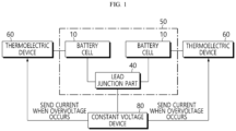
- FIG. 1 is a block diagram illustrating a battery module according to an embodiment of the present disclosure.
- the battery module according to the present disclosure includes a battery cell assembly 50 including a plurality of battery cells 10, a thermoelectric device 60, and a constant voltage device 80.
- a general battery module includes only the plurality of battery cells 10.
- the battery module according to the present disclosure further includes the thermoelectric device 60 and the constant voltage device 80.
- the battery cell assembly 50 has a structure in which side surfaces of the plurality of battery cells 10 are arranged to be adjacent to each other.
- the thermoelectric device 60 has a heat absorbing portion located on the surface of the battery cells 10 which are located at both outsides among the battery cells 10 in the battery cell assembly 50, which correspond to the side surface of the battery cell assembly 50.
- the battery cells 10 have respective leads joined to each other to form lead junction parts 40.
- the constant voltage device 80 may be mounted onto the lead junction part 40.
- the constant voltage device 80 diverts the current of the battery module to the thermoelectric device 60 when overvoltage of the battery module occurs.
- the constant voltage device 80 is a device capable of allowing the current to flow in a desired direction at a breakdown voltage or higher.
- the constant voltage device 80 has a characteristic that allows the current to flow rapidly when a voltage equal to or greater than the breakdown voltage is applied between both terminals. That is, the constant voltage device 80 provided in the present disclosure is a device capable of diverting, i.e. bypassing, the current at the breakdown voltage or higher, and means a device that blocks the current at a voltage lower than the breakdown voltage and allows the current to flow rapidly at a voltage higher than the breakdown voltage.
- a necessary circuit may be configured using the constant voltage device 80 such that the current flows to the thermoelectric device 60 at the breakdown voltage of the constant voltage device 80 or higher.
- a specific value of the breakdown voltage may be appropriately adjusted by those skilled in the art as necessary. In the present disclosure, it is not necessary to use the constant voltage device 80 whose breakdown voltage is higher than needed. The maximum value of the breakdown voltage is different for each battery module.
- the constant voltage device 80 may be applied to the battery module according to the present disclosure to divert the current during overvoltage to the thermoelectric device 60 and drive the thermoelectric device 60. By protecting the battery module from overheating or heat accumulation, the safety of the battery module may be improved.
- the thermoelectric device 60 is driven by the diverted current.
- the thermoelectric device 60 is configured as a Peltier device capable of absorbing and generating heat by current supply. If a heat absorbing portion of the Peltier device is oriented toward the surface of the battery cells 10 located at both outsides among the battery cells 10 inside the battery cell assembly 50 and a heat generating portion of the Peltier device is oriented toward the air, the thermoelectric device 60 may perform electronic cooling by current supply.
- the Peltier device includes the heat absorbing portion and the heat generating portion.
- the heat absorbing portion is in contact with the surface of the battery cells 10 located at both outsides among the battery cells 10 inside the battery cell assembly 50 and the heat generating portion is exposed to the air.
- the Peltier effect refers to a phenomenon in which when any kind of metal is paired to flow the current, a contact of one side generates heat and a contact of the other side absorbs (cools) heat.
- the thermoelectric device 60 of the present disclosure is a device implementing such a Peltier effect, and generally connects n-type and p-type semiconductors formed of an alloy of Group V-VI and a solid solution thereof as cooling contacts through a copper plate at present. If the direction in which the current flows changes, heat absorbing and generating portions may be switched to each other, and the amount of heat absorption and generation may be adjusted according to the amount of current.
- the current flow direction applied to the thermoelectric device 60 is considered such that the heat absorbing portion of the thermoelectric device 60 is in contact with the surface of the battery cells 10 located at both outsides among the battery cells 10 inside the battery cell assembly 50 and the heat generating portion is exposed to the air.
- the thermoelectric device 60 By mounting the thermoelectric device 60 onto the side surface of the battery cell assembly 50 other than the inside of the battery cell 10 or another position within the battery module, preferential cooling of a part with a relatively large area is possible, resulting in the excellent heat dissipation effect.
- heat dissipation to the outside becomes easier and the cooling effect is excellent.
- the constant voltage device 80 and the thermoelectric device 60 may be disposed at a short distance, and thus a structure of the battery module may be simplified.
- the battery module when the overvoltage occurs, the battery module is electronically cooled by driving the thermoelectric device 60 using the current of the battery module. As a result, a phenomenon in which the temperature of the battery module increases rapidly due to overvoltage may be prevented.
- FIG. 2 is a perspective view schematically showing a battery module according to another embodiment of the present disclosure.
- FIG. 3 is a top view of a pouch type battery cell as a unit battery cell included in the battery module of FIG. 2 .
- the battery module 100 of FIG. 2 illustrates an example in which a plurality of battery cells 110a, 110b, 110c, etc. are electrically connected in series. In the present embodiment, an example of a serial connection is given, but battery cells may be connected in series and/or in parallel according to a desired standard.
- Each of the plurality of battery cells 1 10a, 110b, 110c, etc. is a pouch type battery cell 110 as shown in FIG. 3 and may have the same structure.
- the pouch type battery cell 110 is accommodated and sealed in a pouch 115 together with the electrode assembly 120 and an electrolyte.
- the pouch 115 may include a metal layer, an outer resin layer, and an inner resin layer so as to seal the electrode assembly 120 and the electrolyte accommodated therein and protect the electrode assembly 120 and the electrolyte from the outside.
- each of plate shaped positive electrode lead 125 and negative electrode lead 130 is connected to both ends of the electrode assembly 120, and the other end portion thereof is exposed to the outside of the pouch 115.
- One end portion of the positive electrode lead 125 is electrically connected to a positive electrode plate of the electrode assembly 120
- one end portion of the negative electrode lead 130 is electrically connected to a negative electrode plate of the electrode assembly 120.
- the other end portions of the electrode leads 125 and 130 exposed to the outside of the pouch 115 are used to electrically connect a plurality of pouch type battery cells as shown in FIG. 2 .
- a lead film 135 is interposed between the pouch 115 and the electrode leads 125 and 130.
- the lead film 135 is provided to further improve the adhesiveness between the pouch 115 and the electrode leads 125 and 130.
- the lead film 135 may not only prevent a short circuit between the electrode leads 125 and 130 and the metal layer of the pouch 115 may but also improve the sealing property of the pouch 115.
- Thermal welding of the electrode leads 125 and 130 of a metal material and the pouch 115 of a polymer material may cause a somewhat large contact resistance, the surface adhesion may deteriorate.
- the lead film 135 when the lead film 135 is provided, such a phenomenon of deterioration of adhesion may be prevented.
- the lead film 135 may be an insulating material to preferably block the application of current from the electrode leads 125 and 130 to the pouch 115.
- the lead film 135 includes a film having insulation property and thermal welding property.
- the lead film 135 may include any one or more material layers (a single film or a multiple film) selected from, for example, polyimide (PI), polypropylene, polyethylene, polyethylene terephthalate (PET), etc.
- the electrode assembly 120 assembles a unit cell having a structure in which a positive electrode plate and a negative electrode plate are disposed with a separator interposed therebetween.
- the unit cell may be simply stacked, stacked and folded, or manufactured into an electrode assembly in the form of a jelly roll.
- a method of manufacturing an electrode assembly in various types is widely known, and thus a detailed description thereof will be omitted.
- the electrode assembly 120 may be formed by stacking a negative electrode plate, a separator, and a positive electrode plate.
- the electrode assembly 120 may be in the form of a monocell including negative electrode plate/separator/positive electrode plate or a bicell including negative electrode plate/separator/positive electrode plate/separator/negative electrode plate or positive electrode plate/separator/negative electrode plate/separator/positive electrode plate.
- a bidirectional battery in the form in which the positive electrode lead 125 and the negative electrode lead 130 are drawn from the pouch 115 in opposite directions is given, but a unidirectional cell in the form in which both the positive electrode lead 125 and the negative electrode lead 130 are drawn from the pouch 115 in one direction is not excluded.
- the battery cells 110a and 110b are stacked such that the electrode leads protrude from both ends thereof, and the electrode leads have opposite polarities, for example, the positive electrode lead 125a of the battery cell 110a is placed side by side with the negative electrode lead 130b of the battery cell 110b. That is, several battery cells are stacked alternately such that electrode leads placed side by side have opposite polarities.
- the battery cells 1 10a, 1 10b, 110c, etc. are connected in series. In FIG. 2 , a configuration in which the other end portions of the electrode leads 125a and 130b are folded and bent in a left or right side to provide a flat contact surface and then overlap to each other and are connected through welding is illustrated.
- a total number of 11 battery cells are included to configure the battery cell assembly 150.
- the electrode leads of each battery cell are vertically bent such that the electrode leads of the neighboring battery cells and the vertically bent portions overlap each other to form the lead junction parts 140. More specifically, in one side of the stacked battery cells 110a, 110b, 110c, etc. the inside electrode leads except for the electrode leads positioned outside are bent to overlap each other, and then bent electrode lead portions are electrically connected. On the other side of the stacked battery cells 1 10a, 110b, 110c, etc. all the electrode leads are bent to overlap each other and then welded and bent electrode lead portions are electrically connected.
- the battery cells may be stacked without an intermediate medium structure such as a cartridge or a spacer, or may be stacked with each other in a structure in which, for example, the battery cells are stacked in a cartridge including a battery cell accommodation part formed in two units.
- the battery cells 110a, 110b, 110c, etc. are stacked upright in a vertical direction.
- the electrode leads are bent, in the battery cells, the electrode lead of any one side is vertically bent in the right direction (or the outside of the battery module), and the electrode lead of the other side is vertically bent in the left direction (or the inside of the battery module).
- the lead junction part 140 to be coupled is ' ⁇ ' shaped such that the electrode leads of different polarities are bent and overlapped.
- the lead junction parts 140 are arranged side by side along a horizontal direction. This process may be performed in the reverse process, for example, the electrode leads may be first bent, the battery cells are stack in a state where the electrodes leads are bent, and then the corresponding parts may be welded.
- FIG. 2 illustrates a method of overlapping and directly connecting the electrode leads
- an indirect connection method using a bus bar is also possible.
- the present disclosure may be applied to a case in which a battery module is configured by welding a bus bar together with an electrode lead or a battery module is configured by welding an electrode lead and an external circuit.
- FIG. 4 schematically illustrates lead junction parts between two adjacent battery cells in a battery module of FIG. 2 .
- the first battery cell 110a and the second battery cell 110b when two adjacent battery cells in the battery module 100 are referred to as the first battery cell 110a and the second battery cell 110b, the positive electrode lead 125a of the first battery cell 110a and the negative electrode lead 130b of the second battery cell 110b are connected. In this way, the first and second battery cells 110a and 110b are electrically connected in electrical series.
- the connection may be performed by using a method generally used in the art, for example, the battery cells may be coupled and connected by ultrasonic welding, but the present disclosure is not limited thereto.
- the first battery cell 110a is a battery cell located outside, the thermoelectric device 160 is mounted onto the surface of the first battery cell 110a as shown.
- the other end portion of the positive electrode lead 125a of the first battery cell 110a and the other end portion of the negative electrode lead 130b of the second battery cell 110b are bent toward each other along the stack direction of the first and second battery cells 110a and 1 10b, and the lead junction part 140 is formed to include a flat portion in which bent portions bent and provided in the electrode leads 125a and 130b are overlapped and welded.
- a thermoelectric device 160 is mounted onto the flat portion.
- thermoelectric device 160 is mounted onto the surface of battery cells positioned at both outsides among the battery cells 110a, 110b, 110c, etc. inside the battery cell assembly 150. That is, the thermoelectric device 160 is provided on the side surface of the battery cell assembly 150 and may be provided in a plate shape.
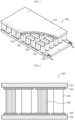
- FIG. 5 is a partially cut perspective view illustrating a thermoelectric device included in a battery module according to the present disclosure.
- FIG. 6 is a front view of the thermoelectric device shown in FIG. 5.
- FIGS. 5 and 6 show a thermoelectric module as an example of the thermoelectric device. Since the thermoelectric module may be manufactured in a plate shape, the thermoelectric module may be easily mounted onto the surface of the battery cell.
- the thermoelectric device 160 may include an upper substrate 161 and a lower substrate 162, metal electrodes 163 disposed on one surface of the upper substrate 161 and the lower substrate 162, and a plurality of p-type thermoelectric semiconductors 164 and n-type thermoelectric semiconductors 165 spaced between the metal electrodes 163.
- the metal electrode 163 allows the current to flow through the p-type thermoelectric semiconductor 164 and the n-type thermoelectric semiconductor 165 when power is applied to the thermoelectric device 160, and more specifically, may include an upper metal electrode provided on the lower surface of the upper substrate 161 and a lower metal electrode provided on the upper surface of the lower substrate 162.
- the metal electrode 163 may be formed of a material having high electrical conductivity in order to minimize the loss of current supplied to the thermoelectric device 160, and more specifically, may be formed of a material having excellent conductivity such as silver or copper.
- the p-type thermoelectric semiconductor 164 and the n-type thermoelectric semiconductor 165 may be spaced apart from each other one by one on one surface of the upper metal electrode and the lower metal electrode.
- the p-type thermoelectric semiconductor 164 may be provided on the left side of the lower surface of the upper electrode, and the n-type thermoelectric semiconductor 165 may be provided spaced to the right side from the p-type thermoelectric semiconductor 164.
- the n-type thermoelectric semiconductor 165 may be provided on the left side of the upper surface of the lower electrode, and the p-type thermoelectric semiconductor 164 may be provided spaced to the right side from the n-type thermoelectric semiconductor 165.
- thermoelectric device 160 When the current is applied to the thermoelectric device 160, the p-type thermoelectric semiconductor 164 and the n-type thermoelectric semiconductor 165 are electrically connected in series, and the current flows. Due to the Peltier effect, holes in the p-type thermoelectric semiconductor 164 move with heat toward the (-) side, and electrons in the n-type thermoelectric semiconductor 165 move with heat toward the (+) side, and thus the upper substrate 161 is heated, and the lower substrate 162 is cooled.
- the lower substrate 162 of the thermoelectric device 160 used in the present disclosure may operate as a heat absorbing portion of the lead junction part 140 in the battery module 100 according to the present disclosure
- the upper substrate 161 may operate as a heat generating portion, and accordingly, it is preferable that the lower substrate 162 is configured to be in thermal contact with the surface of the battery cell.
- the constant voltage device 180 is an element that drives the thermoelectric device 160 by diverting the current of the battery module 100 to the thermoelectric device 160 when the overvoltage of the battery module 100 occurs to enable cooling, called electronic cooling, of the battery cell as described above.
- the constant voltage device 180 is a device capable of allowing a current to flow in a desired direction at a breakdown voltage or higher, and preferably includes a Zener diode or a varistor.
- the Zener diode is a device using the Zener effect.
- the Zener effect is a phenomenon that when a high voltage is applied to a semiconductor or the like, because the energy at the upper end of a valence band is the same as the energy at the lower end of a conduction band in a very close part, the tunnel effect increases the probability of electrons moving from the valence band to the conduction band, resulting in flowing a current.
- the Zener effect is a phenomenon of increase in the current that appears when the probability that a valence moves to the conduction band by the tunnel effect increases due to any strong electric field generated in the semiconductor.
- the Zener diode using these characteristics may be manufactured in a semiconductor p-n junction and is well known as a device having a characteristic that when a relatively large voltage in a reverse direction is applied, a large current starts to flow rapidly at a certain voltage and the voltage remains constant.
- the varistor is a nonlinear semiconductor resistance device whose resistance value changes according to voltages applied to both ends of the varistor and which is an abbreviation of a variable resistor.
- kinds of varistors include symmetric varistors whose resistance is determined only by the magnitude of the voltage regardless of the polarity of the applied voltage, and asymmetric varistors whose resistance varies depending on the polarity of the applied voltage.
- thermoelectric device 160 may be driven in an overvoltage circumstance of the battery module 100 to prevent heat accumulation in the battery module 100.
- the breakdown voltage of the constant voltage device 180 is greater than the full charge voltage of the battery module 100.
- the breakdown voltage may be set to 4.73V which is 10% greater than 4.3V, or 4.945V which is 15% greater than 4.3V, or 5.16V which is 20% greater than 4.3V, to select the constant voltage device 180 corresponding thereto and achieve a circuit configuration.
- the constant voltage device 180 may be used by obtaining a commercially available one. Constant voltage devices having various breakdown voltages are commercially available, and thus those skilled in the art may purchase and use appropriate constant voltage devices as necessary.
- the constant voltage device 180 may be provided in a sensing circuit that senses a voltage state of the battery module 100.
- the normal battery module 100 has a sensing circuit that senses the voltage state and a control circuit that controls charging and discharging of the battery module 100 using the sensed voltage state.
- the battery module 100 may be implemented by further including the constant voltage device 180 in the sensing circuit.
- thermoelectric device 160 a circuit must be provided between the constant voltage device 180 and the thermoelectric device 160 to allow the current of the battery module 100 to flow toward the thermoelectric device 160 when the constant voltage device 180 reaches the breakdown voltage.
- Various circuits for providing a current flow path may be easily implemented by those skilled in the art, and thus detailed descriptions thereof will be omitted.
- the constant voltage device 180 may connect in parallel the positive electrode lead 125a of any one battery cell, for example, the first battery cell 110a and the negative electrode lead 130b of the other one battery cell, for example, the second battery cell 110b among the lead junction parts 140.
- thermoelectric device 160 when the overvoltage occurs, the thermoelectric device 160 is driven by using the current of the battery module 100 to electronically cool the battery module 100. As a result, a phenomenon in which the temperature of the battery module 100 increases rapidly due to overvoltage may be prevented.
- thermoelectric device 160 is mounted onto the side surface of the battery cell assembly 150.
- the thermoelectric device 160 is mounted onto the side surface of the battery cell assembly 150.
- collective preferential cooling of a part with a relatively large area is possible, resulting in the excellent heat dissipation effect.
- heat dissipation to the outside becomes easier and the cooling effect is excellent.
- the constant voltage device 180 and the thermoelectric device 160 may be disposed at a short distance, and thus a structure of the battery module may be simplified.
- the battery module Since the battery module according to the present disclosure has no heat accumulation and has excellent safety, the battery module is also suitable for use as a power source for a medium and large device requiring high temperature stability, long cycle characteristics, high rate characteristics, etc.
- Preferred examples of the medium and large device include a power tool that is driven by an electric motor; electric vehicles including EV, HEV, PHEV, and the like; electric motorcycles including e-bikes and e-scooters; electric golf carts; and ESS, but are not limited thereto.
- a normal battery module includes a protection circuit to prevent overcharging.
- the protection circuit interrupts a charge current or a discharge current by blocking a charge/discharge circuit when a voltage (that is, an overcharge circumstance) equal to or higher than a chargeable voltage or a voltage (that is, the overdischarge circumstance) equal to or lower than a dischargeable voltage is detected.
- a voltage that is, an overcharge circumstance
- a voltage that is, the overdischarge circumstance
- the safety is very weak when the battery module does not operate properly due to the malfunction of the protection circuit.
- the battery module of the present disclosure may greatly improve the heat dissipation characteristics during overvoltage of the battery module regardless of whether the protection circuit is provided, which is a great help in securing safety.
- the constant voltage device of the present disclosure is additionally inserted into the sensing circuit of the existing battery module and constitutes a new circuit, the constant voltage device is easy to utilize.
- the characteristics of an electrolyte and a separator or an electrode structure included in the secondary battery are improved, and predetermined means for preventing overcharging is provided in the electrolyte and the electrode assembly itself, attempts to configure secondary batteries using only bare cells without a protection circuit in terms of the manufacturing cost are increasing.
- a bare cell-based battery module without a protection circuit may be sufficiently utilized as a basic and minimal safety device because the battery module may prevent occurrence of a problem such as heat accumulation during overvoltage with minimal components such as a thermoelectric device and a constant voltage device.
- FIG. 7 is a schematic cross-sectional view of another battery module according to the present disclosure and, for example, corresponds to cross-section VII-VII' of FIG. 2 .
- FIG. 7 an example in which four battery cells are included in the overall configuration of the battery cell assembly 150 is given.
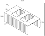
- FIG. 8 illustrates an end plate that may be included in the battery module as shown in FIG. 7 .
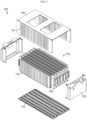
- FIG. 9 is an exploded perspective view of a battery module assembled using the end plate of FIG. 8 .
- the thermoelectric device 160 is provided in a plate shape on a side surface of the battery cell assembly 150.
- the thermoelectric device 160 further includes a plurality of heat dissipation fins 170 protruding in a direction perpendicular to the side surface of the battery cell assembly 150.
- the heat dissipation fins 170 are applied toward the end plate 190 as shown in FIG. 8 .
- a heat dissipation surface area further increases by the heat dissipation fins 170, thereby maximizing the effect of the electronic cooling.
- a battery module 100' further includes the end plate 190 covering the side surface of the battery cell assembly 150. As shown in FIG. 8 , grooves 191 into which the heat dissipation fins 170 are fitted are formed in the end plate 190.
- the grooves 191 may have a step enough to accommodate the heat dissipation fins 170 or may be formed to allow the heat dissipation fins 170 to penetrate the grooves 191. It is preferable to prevent the heat dissipation fins 170 from protruding to the outside of the end plate 190 as much as possible to comply with existing design rules.
- the battery module 100' may further include a module base plate 192, a sub end plate 195, and an end plate 190 in the battery cell assembly 150 as described above.
- the battery cell assembly 150 may be mounted onto the module base plate 192.
- a bus bar assembly (not shown) that electrically connects the battery cells 110 may be mounted onto each of the front and rear surfaces of the battery cell assembly 150.
- the bus bar assembly is electrically connected to electrode leads formed on the battery cells 110 in the battery cell assembly 150 to constitute an electrical connection with an external device.
- a slave battery management system (BMS) (not shown) may be mounted onto one surface of the bus bar assembly and detect the voltage and temperature from the battery cell assembly 150 to control the battery module 100'.
- the sub end plates 195 may be mounted onto the outer surfaces of the bus bar assembly and the slave BMS, respectively.
- the sub end plates 195 prevent the bus bar assembly and the slave BMS from being exposed to the outside.
- the end plate 190 corresponds to an upper housing to have a structure in which the end plate 190 is mounted onto an upper surface of the battery cell assembly 150, coupled to the module base plate 192, and includes the battery cell assembly 150 therein.
- the end plates 190 are located at both sides of the battery cell assembly 150 when the battery module 100' is completed.
- the end plate 190 may include a first plate 190a upright downward, a second plate 190b upright downward while being compatible with the first plate 190a and an upper plate 190c covering the upper surface of the battery cell assembly 150.
- the first plate 190a is in contact with one side of the battery cell assembly 150.
- the second plate 190b is in contact with the other side of the battery cell assembly 150.
- the upper plate 190c has a shape extending from the upper edge of the first plate 190a and the upper edge of the second plate 190b.
- the grooves 191 are formed in the first plate 190a and the second plate 190b.
- the thickness of each of the first plate 190a and the second plate 190b is determined such that an overall appearance is not larger than that of the existing end plate, and thus, the overall size of the battery module 100' is not larger than the existing one.
- the heat dissipation fins 170 are fitted into the grooves 191 formed in the end plate 190.
- the end plate 190 is structured to accommodate and support the battery cell assembly 150 as well as support the thermoelectric device 160 and the heat dissipation fins 170 together.
- heat dissipation is smoother, and the end plate 190 fixes the heat dissipation fins 170, and thus structural robustness may be secured.
- FIG. 10 is a diagram illustrating a battery pack according to still another embodiment of the present disclosure.
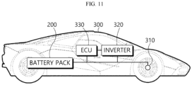
- FIG. 11 is a diagram illustrating a vehicle according to still another embodiment of the present disclosure.
- a battery pack 200 may include at least one battery module according to the foregoing embodiment, for example, the battery module 100 of the second embodiment and a pack case 210 for packaging the battery pack 200.
- the battery pack 200 according to the present disclosure in addition to the battery module 100 and the pack case 210, may further include various devices for controlling charging and discharging of the battery module 100, such as a battery management system (BMS), a current sensor, a fuse, etc.
- BMS battery management system
- the battery pack 200 may be provided in a vehicle 300 as a fuel source of the vehicle 300.
- the battery pack 200 may be provided in the vehicle 300 in other ways that may utilize electric vehicles, hybrid vehicles, and the other battery pack 200 as fuel sources.
- the vehicle 300 may be an electric vehicle.
- the battery pack 200 may be used as an electric energy source that drives the vehicle 300 by providing a driving force to a motor 310 of the electric vehicle.
- the battery pack 200 has a high nominal voltage of 100V or higher.
- the battery pack 200 is set to 270V.
- the battery pack 200 may be charged or discharged by an inverter 320 according to the driving of the motor 310 and/or an internal combustion engine.
- the battery pack 200 may be charged by a regenerative charging device coupled with a break.
- the battery pack 200 may be electrically connected to the motor 310 of the vehicle 300 through the inverter 320.
- the battery pack 200 also includes the BMS.
- the BMS estimates the state of battery cells in the battery pack 200 and manages the battery pack 200 using estimated state information. For example, the BMS estimates and manages state information of the battery pack 200 such as state of charge (SOC) of the battery pack 200, state of health (SOH), maximum input/output power allowance, output voltage, etc.
- the BMS may use the state information to control the charging or discharging of the battery pack 200, and further, estimate the replacement time of the battery pack 200.
- An ECU 330 is an electronic control device for controlling the state of the vehicle 300.
- the ECU 330 determines torque information based on information such as an accelerator, a brake, a speed, etc., and controls the output of the motor 310 to match the torque information.
- the ECU 330 transmits a control signal to the inverter 320 such that the battery pack 200 may be charged or discharged based on the state information such as SOC and SOH of the battery pack 200 received by the BMS.
- the inverter 320 causes the battery pack 200 to be charged or discharged based on the control signal of the ECU 330.
- the motor 310 drives the vehicle 300 based on control information (e.g., torque information) transmitted from the ECU 330 using electric energy of the battery pack 200.
- the vehicle 300 includes the battery pack 200 according to the present disclosure.
- the battery pack 200 includes the battery module 100 with improved safety as described above. Therefore, the stability of the battery pack 200 is improved, the battery pack 200 is excellent in stability and may be used for a long time, and thus the vehicle 300 including the battery pack 200 is safe and easy to operate.
- the battery pack 200 may also be provided in other devices, equipment, and facilities, such as an ESS using a secondary battery, in addition to the vehicle 300.
- the battery pack 200 according to the present embodiment and devices or equipment and facilities including the battery pack 200, such as the vehicle 300 include the battery module 100 described above, and thus the battery pack 200 having all the advantages owing to the battery module 100 described above and devices or equipment and facilities such as the vehicle 300 including the battery pack 200 may be implemented.
Landscapes
- Chemical & Material Sciences (AREA)
- Chemical Kinetics & Catalysis (AREA)
- Electrochemistry (AREA)
- General Chemical & Material Sciences (AREA)
- Engineering & Computer Science (AREA)
- Manufacturing & Machinery (AREA)
- Physics & Mathematics (AREA)
- Electromagnetism (AREA)
- Aviation & Aerospace Engineering (AREA)
- Power Engineering (AREA)
- General Physics & Mathematics (AREA)
- Battery Mounting, Suspending (AREA)
- Secondary Cells (AREA)
- Connection Of Batteries Or Terminals (AREA)
Claims (11)
- Batteriemodul (100), umfassend eine Batteriezellenanordnung (150), welche eine Mehrzahl beutelartiger Batteriezellen (110) und Leitungsverbindungsteile (140) umfasst, in welchen jeweilige Leitungen (125, 130) der Batteriezellen (110) miteinander verbunden sind, wobei das Batteriemodul (100) umfasst:eine thermoelektrische Vorrichtung (160), in welcher ein wärmeabsorbierender Abschnitt an Flächen der Batteriezellen (110) angeordnet ist, welche an beiden Außenseiten unter den Batteriezellen (110) in der Batteriezellenanordnung (150) angeordnet sind, wobei die Flächen der Batteriezellen (110) einer Seitenfläche der Batteriezellenanordnung (150) entsprechen, gekennzeichnet durcheine Konstantspannungsvorrichtung (180), welche dazu eingerichtet ist, einen Strom des Batteriemoduls (100) zu der thermoelektrischen Vorrichtung (160) umzuleiten, wenn eine Überspannung des Batteriemoduls (100) auftritt,wobei die thermoelektrische Vorrichtung (160) angetrieben wird, um die Batteriezellenanordnung (150) des Batteriemoduls (100) elektronisch zu kühlen, wenn die Überspannung des Batteriemoduls (100) auftritt.
- Batteriemodul (100) nach Anspruch 1, wobei die Konstantspannungsvorrichtung (180) an dem Leitungsverbindungsteil (140) montiert ist.
- Batteriemodul (100) nach Anspruch 2, wobei die Konstantspannungsvorrichtung (180) zwischen eine positive Elektrodenleitung (125) jeglicher Batteriezelle (110) und eine negative Elektrodenleitung (130) der anderen Batteriezelle unter den Leitungsverbindungsteilen (140) parallel geschaltet ist.
- Batteriemodul (100) nach Anspruch 1, wobei die Konstantspannungsvorrichtung (180) eine Zenerdiode oder ein Varistor ist.
- Batteriemodul (100) nach Anspruch 1, wobei eine Durchbruchspannung der Konstantspannungsvorrichtung (180) größer ist als eine volle Ladespannung des Batteriemoduls (100).
- Batteriemodul (100) nach Anspruch 1, wobei die Konstantspannungsvorrichtung (180) in einer Erfassungsschaltung bereitgestellt ist, welche einen Spannungszustand des Batteriemoduls (100) erfasst, und wobei eine Schaltung, welche dazu in der Lage ist, zu erlauben, dass der Strom des Batteriemoduls (100) in Richtung der thermoelektrischen Vorrichtung (160) fließt, wenn die Durchbruchspannung der Konstantspannungsvorrichtung (180) erreicht ist, zwischen der Konstantspannungsvorrichtung (180) und der thermoelektrischen Vorrichtung (160) bereitgestellt ist.
- Batteriemodul (100) nach Anspruch 1, wobei die thermoelektrische Vorrichtung (160) in einer Plattenform an der Seitenfläche der Batteriezellenanordnung (150) bereitgestellt ist.
- Batteriemodul (100) nach Anspruch 7, ferner umfassend eine Mehrzahl von Wärmeableitungsrippen (170), welche an der thermoelektrischen Vorrichtung (160) in einer zu der Seitenfläche der Batteriezellenanordnung (150) senkrechten Richtung vorstehen.
- Batteriemodul (100) nach Anspruch 8, ferner umfassend eine Endplatte (190), welche die Seitenfläche der Batteriezellenanordnung (150) abdeckt,
wobei Nuten (191), in welche die Wärmeableitungsrippen (170) eingepasst sind, in der Endplatte (190) gebildet sind. - Batteriepack (200), umfassend:wenigstens ein Batteriemodul (100) nach einem der Ansprüche 1 bis 9; undein Packgehäuse (210), welches dazu eingerichtet ist, das wenigstens eine Batteriemodul (100) zu verpacken.
- Fahrzeug (300), umfassend wenigstens einen Batteriepack (200) nach Anspruch 10.
Applications Claiming Priority (2)
| Application Number | Priority Date | Filing Date | Title |
|---|---|---|---|
| KR1020180151276A KR102394742B1 (ko) | 2018-11-29 | 2018-11-29 | 열 방출이 개선된 배터리 모듈, 이러한 배터리 모듈을 포함하는 배터리 팩 및 이러한 배터리 팩을 포함하는 자동차 |
| PCT/KR2019/015084 WO2020111564A1 (ko) | 2018-11-29 | 2019-11-07 | 열 방출이 개선된 배터리 모듈, 이러한 배터리 모듈을 포함하는 배터리 팩 및 이러한 배터리 팩을 포함하는 자동차 |
Publications (3)
| Publication Number | Publication Date |
|---|---|
| EP3836294A1 EP3836294A1 (de) | 2021-06-16 |
| EP3836294A4 EP3836294A4 (de) | 2021-11-03 |
| EP3836294B1 true EP3836294B1 (de) | 2024-08-21 |
Family
ID=70854050
Family Applications (1)
| Application Number | Title | Priority Date | Filing Date |
|---|---|---|---|
| EP19891450.9A Active EP3836294B1 (de) | 2018-11-29 | 2019-11-07 | Batteriemodul mit verbesserter wärmeableitung, batteriepack mit batteriemodul und fahrzeug mit diesem batteriepack |
Country Status (8)
| Country | Link |
|---|---|
| US (1) | US11342613B2 (de) |
| EP (1) | EP3836294B1 (de) |
| JP (1) | JP7176006B2 (de) |
| KR (1) | KR102394742B1 (de) |
| CN (1) | CN112088462B (de) |
| ES (1) | ES2986425T3 (de) |
| HU (1) | HUE068296T2 (de) |
| WO (1) | WO2020111564A1 (de) |
Families Citing this family (12)
| Publication number | Priority date | Publication date | Assignee | Title |
|---|---|---|---|---|
| KR102394741B1 (ko) * | 2018-11-29 | 2022-05-06 | 주식회사 엘지에너지솔루션 | 열 방출이 개선된 배터리 모듈, 이러한 배터리 모듈을 포함하는 배터리 팩 및 이러한 배터리 팩을 포함하는 자동차 |
| JP7177752B2 (ja) * | 2019-06-05 | 2022-11-24 | カワサキモータース株式会社 | 乗物の電池パック |
| WO2021241041A1 (ja) * | 2020-05-29 | 2021-12-02 | ソニーグループ株式会社 | 移動体、移動体の制御方法、移動体の制御プログラムおよび電源システム |
| KR102923747B1 (ko) * | 2020-10-21 | 2026-02-04 | 에스케이온 주식회사 | 이차 전지 |
| JP7317876B2 (ja) | 2021-02-08 | 2023-07-31 | プライムプラネットエナジー&ソリューションズ株式会社 | 組電池 |
| JP7371659B2 (ja) * | 2021-03-31 | 2023-10-31 | トヨタ自動車株式会社 | 蓄電装置 |
| KR20220150004A (ko) * | 2021-05-03 | 2022-11-10 | 에스케이온 주식회사 | 이차 전지 |
| US12081050B2 (en) | 2021-10-31 | 2024-09-03 | Beta Air, Llc | System for overvoltage protection in an electric aircraft and a method for its use |
| US11424630B1 (en) | 2021-10-31 | 2022-08-23 | Beta Air, Llc | System for overvoltage protection in an electric aircraft and a method for its use |
| US11824176B2 (en) | 2022-03-25 | 2023-11-21 | Beta Air, Llc | Systems and methods for battery pack cooling using a cooling fin |
| US11784500B1 (en) | 2022-04-28 | 2023-10-10 | Beta Air, Llc | Systems and methods for overvoltage protection on loads for use in an electric aircraft |
| KR20240087407A (ko) | 2022-12-12 | 2024-06-19 | 주식회사 엘지에너지솔루션 | 배터리 모듈 |
Family Cites Families (29)
| Publication number | Priority date | Publication date | Assignee | Title |
|---|---|---|---|---|
| JP3697724B2 (ja) * | 1994-09-14 | 2005-09-21 | 日産自動車株式会社 | 組電池の異常検出装置 |
| WO1999039421A1 (en) * | 1998-01-31 | 1999-08-05 | Oglesbee John W | Supplemental battery overcharge protection device |
| JPH11284235A (ja) | 1998-03-27 | 1999-10-15 | Union Material Kk | 熱電充電器および熱電充電器一体型二次電池 |
| US7592776B2 (en) * | 2001-11-07 | 2009-09-22 | Quallion Llc | Energy storage device configured to discharge energy in response to unsafe conditions |
| JP4374977B2 (ja) * | 2003-10-10 | 2009-12-02 | 日産自動車株式会社 | 組電池 |
| JP2008504665A (ja) | 2004-08-20 | 2008-02-14 | エルジー・ケム・リミテッド | 定電圧素子を有する2次電池 |
| KR100745354B1 (ko) * | 2004-08-24 | 2007-08-02 | 주식회사 엘지화학 | 이차전지의 과충전 방지를 위한 안전 소자 및 그 안전소자가 결합된 이차전지 |
| WO2006055442A2 (en) * | 2004-11-15 | 2006-05-26 | William Stanton | Uninterruptible power supply system |
| JP2008010295A (ja) | 2006-06-29 | 2008-01-17 | Hokuriku Electric Power Co Inc:The | 二次電池の保温方法及び保温装置 |
| KR20110015070A (ko) | 2009-08-07 | 2011-02-15 | 주식회사 엘지화학 | 외부단락 안전성 확보용 배터리 |
| US20110048485A1 (en) * | 2009-09-02 | 2011-03-03 | Lonnie Calvin Goff | Integrated battery management system for vehicles |
| KR101108191B1 (ko) * | 2010-05-24 | 2012-02-06 | 에스비리모티브 주식회사 | 배터리 팩 |
| KR101382663B1 (ko) * | 2011-11-30 | 2014-04-14 | 서울과학기술대학교 산학협력단 | 방전 프로파일에 따라 배터리의 방전을 유도하는 방전 시스템에서 사용되는 냉각 장치 및 그 장치의 제조 방법 |
| KR101522164B1 (ko) | 2012-06-12 | 2015-05-22 | 주식회사 엘지화학 | 온도 조절을 위한 펠티어 소자를 포함하고 있는 전지팩 |
| DE102012215056B4 (de) * | 2012-08-24 | 2021-09-02 | Robert Bosch Gmbh | Batteriesystem und Kraftfahrzeug |
| WO2014110524A1 (en) * | 2013-01-14 | 2014-07-17 | Gentherm Incorporated | Thermoelectric-based thermal management of electrical devices |
| KR101526389B1 (ko) | 2013-06-11 | 2015-06-05 | 현대자동차 주식회사 | 전기차용 배터리의 열관리 장치 |
| CN106030898B (zh) * | 2013-10-29 | 2019-04-05 | 詹思姆公司 | 利用热电学的电池热管理 |
| KR101738104B1 (ko) * | 2014-07-08 | 2017-05-19 | 주식회사 엘지화학 | 과전류 방지 기능을 갖는 전지 모듈 |
| KR102100932B1 (ko) | 2015-05-08 | 2020-04-14 | 주식회사 엘지화학 | 전기적 연결 구조를 다변화할 수 있는 전지셀 및 이를 포함하는 전지셀 어셈블리 |
| WO2016200943A1 (en) | 2015-06-10 | 2016-12-15 | Gentherm Inc. | Vehicle battery thermoelectric device with integrated cold plate assembly and method of assembling same |
| KR101734717B1 (ko) | 2015-12-11 | 2017-05-24 | 현대자동차주식회사 | 차량용 배터리 및 그 제어 방법 |
| US10326442B2 (en) * | 2015-12-29 | 2019-06-18 | Lear Corporation | Assembly having internally configurable solid-state switch arrangement for use as one or more disconnection switches in electrical systems and having external package common to the electrical systems |
| KR101990107B1 (ko) | 2016-03-29 | 2019-06-19 | 주식회사 아모그린텍 | 방열 모듈 및 이용한 전기자동차용 전지팩 |
| KR20180022250A (ko) * | 2016-08-24 | 2018-03-06 | 이승규 | 솔더링 장치, 이를 이용한 솔더링 연결 방법 |
| CN206250324U (zh) * | 2016-12-02 | 2017-06-13 | 天津市德泰隆科技股份有限公司 | 一种具有高散热性的铅酸蓄电池 |
| KR102360159B1 (ko) * | 2017-03-20 | 2022-02-09 | 현대자동차주식회사 | 배터리 모듈 |
| KR102192188B1 (ko) * | 2017-04-17 | 2020-12-16 | 주식회사 엘지화학 | 과충전 방지 장치 및 방법 |
| CN108461835A (zh) * | 2018-02-13 | 2018-08-28 | 天津大学 | 一种基于珀尔帖效应的电动汽车电池紧急降温系统 |
-
2018
- 2018-11-29 KR KR1020180151276A patent/KR102394742B1/ko active Active
-
2019
- 2019-11-07 ES ES19891450T patent/ES2986425T3/es active Active
- 2019-11-07 CN CN201980030543.9A patent/CN112088462B/zh active Active
- 2019-11-07 WO PCT/KR2019/015084 patent/WO2020111564A1/ko not_active Ceased
- 2019-11-07 EP EP19891450.9A patent/EP3836294B1/de active Active
- 2019-11-07 HU HUE19891450A patent/HUE068296T2/hu unknown
- 2019-11-07 JP JP2020566262A patent/JP7176006B2/ja active Active
- 2019-11-07 US US17/049,854 patent/US11342613B2/en active Active
Also Published As
| Publication number | Publication date |
|---|---|
| EP3836294A1 (de) | 2021-06-16 |
| CN112088462B (zh) | 2024-03-22 |
| JP2021524990A (ja) | 2021-09-16 |
| KR102394742B1 (ko) | 2022-05-06 |
| US11342613B2 (en) | 2022-05-24 |
| EP3836294A4 (de) | 2021-11-03 |
| KR20200065194A (ko) | 2020-06-09 |
| US20210257693A1 (en) | 2021-08-19 |
| WO2020111564A1 (ko) | 2020-06-04 |
| HUE068296T2 (hu) | 2024-12-28 |
| ES2986425T3 (es) | 2024-11-11 |
| JP7176006B2 (ja) | 2022-11-21 |
| CN112088462A (zh) | 2020-12-15 |
Similar Documents
| Publication | Publication Date | Title |
|---|---|---|
| EP3836294B1 (de) | Batteriemodul mit verbesserter wärmeableitung, batteriepack mit batteriemodul und fahrzeug mit diesem batteriepack | |
| EP3809513B1 (de) | Batteriemodul mit verbesserter wärmeableitung, batteriepack mit diesem batteriemodul und fahrzeug mit diesem batteriepack | |
| JP6047810B2 (ja) | 二次電池、これを含む二次電池モジュール及び二次電池パック | |
| EP3843178B1 (de) | Batteriemodul mit verbesserter sicherheit, batteriepack mit batteriemodul und fahrzeug mit batteriepack | |
| US11881597B2 (en) | Battery module with improved safety, battery pack comprising battery module, and vehicle comprising battery pack | |
| KR102267056B1 (ko) | 배터리 모듈과 이를 포함하는 배터리 팩 및 자동차 | |
| KR102903027B1 (ko) | 안전성이 개선된 배터리 모듈, 이러한 배터리 모듈을 포함하는 배터리 팩 및 이러한 배터리 팩을 포함하는 자동차 | |
| KR20250059892A (ko) | 전지팩 및 이를 포함하는 디바이스 |
Legal Events
| Date | Code | Title | Description |
|---|---|---|---|
| STAA | Information on the status of an ep patent application or granted ep patent |
Free format text: STATUS: THE INTERNATIONAL PUBLICATION HAS BEEN MADE |
|
| PUAI | Public reference made under article 153(3) epc to a published international application that has entered the european phase |
Free format text: ORIGINAL CODE: 0009012 |
|
| STAA | Information on the status of an ep patent application or granted ep patent |
Free format text: STATUS: REQUEST FOR EXAMINATION WAS MADE |
|
| 17P | Request for examination filed |
Effective date: 20210308 |
|
| AK | Designated contracting states |
Kind code of ref document: A1 Designated state(s): AL AT BE BG CH CY CZ DE DK EE ES FI FR GB GR HR HU IE IS IT LI LT LU LV MC MK MT NL NO PL PT RO RS SE SI SK SM TR |
|
| A4 | Supplementary search report drawn up and despatched |
Effective date: 20211001 |
|
| RIC1 | Information provided on ipc code assigned before grant |
Ipc: H01M 50/249 20210101ALI20210927BHEP Ipc: H01M 50/211 20210101ALI20210927BHEP Ipc: H01M 10/625 20140101ALI20210927BHEP Ipc: H01M 10/647 20140101ALI20210927BHEP Ipc: H01M 10/613 20140101ALI20210927BHEP Ipc: H01M 10/6551 20140101ALI20210927BHEP Ipc: H01M 10/6553 20140101ALI20210927BHEP Ipc: H01M 10/6572 20140101AFI20210927BHEP |
|
| RAP1 | Party data changed (applicant data changed or rights of an application transferred) |
Owner name: LG ENERGY SOLUTION LTD. |
|
| DAV | Request for validation of the european patent (deleted) | ||
| DAX | Request for extension of the european patent (deleted) | ||
| RAP3 | Party data changed (applicant data changed or rights of an application transferred) |
Owner name: LG ENERGY SOLUTION, LTD. |
|
| GRAP | Despatch of communication of intention to grant a patent |
Free format text: ORIGINAL CODE: EPIDOSNIGR1 |
|
| STAA | Information on the status of an ep patent application or granted ep patent |
Free format text: STATUS: GRANT OF PATENT IS INTENDED |
|
| INTG | Intention to grant announced |
Effective date: 20240410 |
|
| P01 | Opt-out of the competence of the unified patent court (upc) registered |
Effective date: 20240430 |
|
| GRAS | Grant fee paid |
Free format text: ORIGINAL CODE: EPIDOSNIGR3 |
|
| GRAA | (expected) grant |
Free format text: ORIGINAL CODE: 0009210 |
|
| STAA | Information on the status of an ep patent application or granted ep patent |
Free format text: STATUS: THE PATENT HAS BEEN GRANTED |
|
| AK | Designated contracting states |
Kind code of ref document: B1 Designated state(s): AL AT BE BG CH CY CZ DE DK EE ES FI FR GB GR HR HU IE IS IT LI LT LU LV MC MK MT NL NO PL PT RO RS SE SI SK SM TR |
|
| REG | Reference to a national code |
Ref country code: GB Ref legal event code: FG4D |
|
| REG | Reference to a national code |
Ref country code: CH Ref legal event code: EP |
|
| REG | Reference to a national code |
Ref country code: DE Ref legal event code: R096 Ref document number: 602019057641 Country of ref document: DE |
|
| REG | Reference to a national code |
Ref country code: IE Ref legal event code: FG4D |
|
| REG | Reference to a national code |
Ref country code: ES Ref legal event code: FG2A Ref document number: 2986425 Country of ref document: ES Kind code of ref document: T3 Effective date: 20241111 |
|
| REG | Reference to a national code |
Ref country code: LT Ref legal event code: MG9D |
|
| REG | Reference to a national code |
Ref country code: HU Ref legal event code: AG4A Ref document number: E068296 Country of ref document: HU |
|
| REG | Reference to a national code |
Ref country code: NL Ref legal event code: MP Effective date: 20240821 |
|
| PG25 | Lapsed in a contracting state [announced via postgrant information from national office to epo] |
Ref country code: NO Free format text: LAPSE BECAUSE OF FAILURE TO SUBMIT A TRANSLATION OF THE DESCRIPTION OR TO PAY THE FEE WITHIN THE PRESCRIBED TIME-LIMIT Effective date: 20241121 |
|
| REG | Reference to a national code |
Ref country code: AT Ref legal event code: MK05 Ref document number: 1716436 Country of ref document: AT Kind code of ref document: T Effective date: 20240821 |
|
| PG25 | Lapsed in a contracting state [announced via postgrant information from national office to epo] |
Ref country code: NL Free format text: LAPSE BECAUSE OF FAILURE TO SUBMIT A TRANSLATION OF THE DESCRIPTION OR TO PAY THE FEE WITHIN THE PRESCRIBED TIME-LIMIT Effective date: 20240821 Ref country code: FI Free format text: LAPSE BECAUSE OF FAILURE TO SUBMIT A TRANSLATION OF THE DESCRIPTION OR TO PAY THE FEE WITHIN THE PRESCRIBED TIME-LIMIT Effective date: 20240821 Ref country code: PL Free format text: LAPSE BECAUSE OF FAILURE TO SUBMIT A TRANSLATION OF THE DESCRIPTION OR TO PAY THE FEE WITHIN THE PRESCRIBED TIME-LIMIT Effective date: 20240821 Ref country code: GR Free format text: LAPSE BECAUSE OF FAILURE TO SUBMIT A TRANSLATION OF THE DESCRIPTION OR TO PAY THE FEE WITHIN THE PRESCRIBED TIME-LIMIT Effective date: 20241122 Ref country code: PT Free format text: LAPSE BECAUSE OF FAILURE TO SUBMIT A TRANSLATION OF THE DESCRIPTION OR TO PAY THE FEE WITHIN THE PRESCRIBED TIME-LIMIT Effective date: 20241223 |
|
| PG25 | Lapsed in a contracting state [announced via postgrant information from national office to epo] |
Ref country code: BG Free format text: LAPSE BECAUSE OF FAILURE TO SUBMIT A TRANSLATION OF THE DESCRIPTION OR TO PAY THE FEE WITHIN THE PRESCRIBED TIME-LIMIT Effective date: 20240821 |
|
| PG25 | Lapsed in a contracting state [announced via postgrant information from national office to epo] |
Ref country code: LV Free format text: LAPSE BECAUSE OF FAILURE TO SUBMIT A TRANSLATION OF THE DESCRIPTION OR TO PAY THE FEE WITHIN THE PRESCRIBED TIME-LIMIT Effective date: 20240821 |
|
| PG25 | Lapsed in a contracting state [announced via postgrant information from national office to epo] |
Ref country code: AT Free format text: LAPSE BECAUSE OF FAILURE TO SUBMIT A TRANSLATION OF THE DESCRIPTION OR TO PAY THE FEE WITHIN THE PRESCRIBED TIME-LIMIT Effective date: 20240821 Ref country code: IS Free format text: LAPSE BECAUSE OF FAILURE TO SUBMIT A TRANSLATION OF THE DESCRIPTION OR TO PAY THE FEE WITHIN THE PRESCRIBED TIME-LIMIT Effective date: 20241221 |
|
| PG25 | Lapsed in a contracting state [announced via postgrant information from national office to epo] |
Ref country code: HR Free format text: LAPSE BECAUSE OF FAILURE TO SUBMIT A TRANSLATION OF THE DESCRIPTION OR TO PAY THE FEE WITHIN THE PRESCRIBED TIME-LIMIT Effective date: 20240821 |
|
| PG25 | Lapsed in a contracting state [announced via postgrant information from national office to epo] |
Ref country code: RS Free format text: LAPSE BECAUSE OF FAILURE TO SUBMIT A TRANSLATION OF THE DESCRIPTION OR TO PAY THE FEE WITHIN THE PRESCRIBED TIME-LIMIT Effective date: 20241121 |
|
| PG25 | Lapsed in a contracting state [announced via postgrant information from national office to epo] |
Ref country code: RS Free format text: LAPSE BECAUSE OF FAILURE TO SUBMIT A TRANSLATION OF THE DESCRIPTION OR TO PAY THE FEE WITHIN THE PRESCRIBED TIME-LIMIT Effective date: 20241121 Ref country code: PT Free format text: LAPSE BECAUSE OF FAILURE TO SUBMIT A TRANSLATION OF THE DESCRIPTION OR TO PAY THE FEE WITHIN THE PRESCRIBED TIME-LIMIT Effective date: 20241223 Ref country code: PL Free format text: LAPSE BECAUSE OF FAILURE TO SUBMIT A TRANSLATION OF THE DESCRIPTION OR TO PAY THE FEE WITHIN THE PRESCRIBED TIME-LIMIT Effective date: 20240821 Ref country code: NO Free format text: LAPSE BECAUSE OF FAILURE TO SUBMIT A TRANSLATION OF THE DESCRIPTION OR TO PAY THE FEE WITHIN THE PRESCRIBED TIME-LIMIT Effective date: 20241121 Ref country code: NL Free format text: LAPSE BECAUSE OF FAILURE TO SUBMIT A TRANSLATION OF THE DESCRIPTION OR TO PAY THE FEE WITHIN THE PRESCRIBED TIME-LIMIT Effective date: 20240821 Ref country code: LV Free format text: LAPSE BECAUSE OF FAILURE TO SUBMIT A TRANSLATION OF THE DESCRIPTION OR TO PAY THE FEE WITHIN THE PRESCRIBED TIME-LIMIT Effective date: 20240821 Ref country code: IS Free format text: LAPSE BECAUSE OF FAILURE TO SUBMIT A TRANSLATION OF THE DESCRIPTION OR TO PAY THE FEE WITHIN THE PRESCRIBED TIME-LIMIT Effective date: 20241221 Ref country code: HR Free format text: LAPSE BECAUSE OF FAILURE TO SUBMIT A TRANSLATION OF THE DESCRIPTION OR TO PAY THE FEE WITHIN THE PRESCRIBED TIME-LIMIT Effective date: 20240821 Ref country code: GR Free format text: LAPSE BECAUSE OF FAILURE TO SUBMIT A TRANSLATION OF THE DESCRIPTION OR TO PAY THE FEE WITHIN THE PRESCRIBED TIME-LIMIT Effective date: 20241122 Ref country code: FI Free format text: LAPSE BECAUSE OF FAILURE TO SUBMIT A TRANSLATION OF THE DESCRIPTION OR TO PAY THE FEE WITHIN THE PRESCRIBED TIME-LIMIT Effective date: 20240821 Ref country code: BG Free format text: LAPSE BECAUSE OF FAILURE TO SUBMIT A TRANSLATION OF THE DESCRIPTION OR TO PAY THE FEE WITHIN THE PRESCRIBED TIME-LIMIT Effective date: 20240821 Ref country code: AT Free format text: LAPSE BECAUSE OF FAILURE TO SUBMIT A TRANSLATION OF THE DESCRIPTION OR TO PAY THE FEE WITHIN THE PRESCRIBED TIME-LIMIT Effective date: 20240821 |
|
| PG25 | Lapsed in a contracting state [announced via postgrant information from national office to epo] |
Ref country code: SM Free format text: LAPSE BECAUSE OF FAILURE TO SUBMIT A TRANSLATION OF THE DESCRIPTION OR TO PAY THE FEE WITHIN THE PRESCRIBED TIME-LIMIT Effective date: 20240821 Ref country code: DK Free format text: LAPSE BECAUSE OF FAILURE TO SUBMIT A TRANSLATION OF THE DESCRIPTION OR TO PAY THE FEE WITHIN THE PRESCRIBED TIME-LIMIT Effective date: 20240821 Ref country code: RO Free format text: LAPSE BECAUSE OF FAILURE TO SUBMIT A TRANSLATION OF THE DESCRIPTION OR TO PAY THE FEE WITHIN THE PRESCRIBED TIME-LIMIT Effective date: 20240821 |
|
| PG25 | Lapsed in a contracting state [announced via postgrant information from national office to epo] |
Ref country code: EE Free format text: LAPSE BECAUSE OF FAILURE TO SUBMIT A TRANSLATION OF THE DESCRIPTION OR TO PAY THE FEE WITHIN THE PRESCRIBED TIME-LIMIT Effective date: 20240821 |
|
| PG25 | Lapsed in a contracting state [announced via postgrant information from national office to epo] |
Ref country code: CZ Free format text: LAPSE BECAUSE OF FAILURE TO SUBMIT A TRANSLATION OF THE DESCRIPTION OR TO PAY THE FEE WITHIN THE PRESCRIBED TIME-LIMIT Effective date: 20240821 |
|
| PG25 | Lapsed in a contracting state [announced via postgrant information from national office to epo] |
Ref country code: IT Free format text: LAPSE BECAUSE OF FAILURE TO SUBMIT A TRANSLATION OF THE DESCRIPTION OR TO PAY THE FEE WITHIN THE PRESCRIBED TIME-LIMIT Effective date: 20240821 Ref country code: SK Free format text: LAPSE BECAUSE OF FAILURE TO SUBMIT A TRANSLATION OF THE DESCRIPTION OR TO PAY THE FEE WITHIN THE PRESCRIBED TIME-LIMIT Effective date: 20240821 |
|
| REG | Reference to a national code |
Ref country code: DE Ref legal event code: R097 Ref document number: 602019057641 Country of ref document: DE |
|
| PLBE | No opposition filed within time limit |
Free format text: ORIGINAL CODE: 0009261 |
|
| STAA | Information on the status of an ep patent application or granted ep patent |
Free format text: STATUS: NO OPPOSITION FILED WITHIN TIME LIMIT |
|
| REG | Reference to a national code |
Ref country code: CH Ref legal event code: PL |
|
| PG25 | Lapsed in a contracting state [announced via postgrant information from national office to epo] |
Ref country code: MC Free format text: LAPSE BECAUSE OF FAILURE TO SUBMIT A TRANSLATION OF THE DESCRIPTION OR TO PAY THE FEE WITHIN THE PRESCRIBED TIME-LIMIT Effective date: 20240821 |
|
| PG25 | Lapsed in a contracting state [announced via postgrant information from national office to epo] |
Ref country code: LU Free format text: LAPSE BECAUSE OF NON-PAYMENT OF DUE FEES Effective date: 20241107 |
|
| REG | Reference to a national code |
Ref country code: CH Ref legal event code: PL |
|
| PG25 | Lapsed in a contracting state [announced via postgrant information from national office to epo] |
Ref country code: CH Free format text: LAPSE BECAUSE OF NON-PAYMENT OF DUE FEES Effective date: 20241130 |
|
| 26N | No opposition filed |
Effective date: 20250522 |
|
| PG25 | Lapsed in a contracting state [announced via postgrant information from national office to epo] |
Ref country code: SE Free format text: LAPSE BECAUSE OF FAILURE TO SUBMIT A TRANSLATION OF THE DESCRIPTION OR TO PAY THE FEE WITHIN THE PRESCRIBED TIME-LIMIT Effective date: 20240821 |
|
| PG25 | Lapsed in a contracting state [announced via postgrant information from national office to epo] |
Ref country code: IE Free format text: LAPSE BECAUSE OF NON-PAYMENT OF DUE FEES Effective date: 20241107 |
|
| PGFP | Annual fee paid to national office [announced via postgrant information from national office to epo] |
Ref country code: HU Payment date: 20251127 Year of fee payment: 7 |
|
| PGFP | Annual fee paid to national office [announced via postgrant information from national office to epo] |
Ref country code: DE Payment date: 20251020 Year of fee payment: 7 |
|
| PGFP | Annual fee paid to national office [announced via postgrant information from national office to epo] |
Ref country code: GB Payment date: 20251023 Year of fee payment: 7 |
|
| PGFP | Annual fee paid to national office [announced via postgrant information from national office to epo] |
Ref country code: FR Payment date: 20251021 Year of fee payment: 7 |
|
| PGFP | Annual fee paid to national office [announced via postgrant information from national office to epo] |
Ref country code: BE Payment date: 20251020 Year of fee payment: 7 |
|
| PGFP | Annual fee paid to national office [announced via postgrant information from national office to epo] |
Ref country code: ES Payment date: 20251215 Year of fee payment: 7 |
|
| PG25 | Lapsed in a contracting state [announced via postgrant information from national office to epo] |
Ref country code: CY Free format text: LAPSE BECAUSE OF FAILURE TO SUBMIT A TRANSLATION OF THE DESCRIPTION OR TO PAY THE FEE WITHIN THE PRESCRIBED TIME-LIMIT; INVALID AB INITIO Effective date: 20191107 |