EP3836409B1 - Funk mit geringer leistungsaufnahme und grosser reichweite - Google Patents
Funk mit geringer leistungsaufnahme und grosser reichweite Download PDFInfo
- Publication number
- EP3836409B1 EP3836409B1 EP19215072.0A EP19215072A EP3836409B1 EP 3836409 B1 EP3836409 B1 EP 3836409B1 EP 19215072 A EP19215072 A EP 19215072A EP 3836409 B1 EP3836409 B1 EP 3836409B1
- Authority
- EP
- European Patent Office
- Prior art keywords
- symbols
- differential
- symbol
- series
- encoded
- Prior art date
- Legal status (The legal status is an assumption and is not a legal conclusion. Google has not performed a legal analysis and makes no representation as to the accuracy of the status listed.)
- Active
Links
Images

Classifications
-
- H—ELECTRICITY
- H04—ELECTRIC COMMUNICATION TECHNIQUE
- H04L—TRANSMISSION OF DIGITAL INFORMATION, e.g. TELEGRAPHIC COMMUNICATION
- H04L1/00—Arrangements for detecting or preventing errors in the information received
- H04L1/08—Arrangements for detecting or preventing errors in the information received by repeating transmission, e.g. Verdan system
-
- H—ELECTRICITY
- H04—ELECTRIC COMMUNICATION TECHNIQUE
- H04B—TRANSMISSION
- H04B1/00—Details of transmission systems, not covered by a single one of groups H04B3/00 - H04B13/00; Details of transmission systems not characterised by the medium used for transmission
- H04B1/02—Transmitters
- H04B1/04—Circuits
-
- H—ELECTRICITY
- H04—ELECTRIC COMMUNICATION TECHNIQUE
- H04B—TRANSMISSION
- H04B1/00—Details of transmission systems, not covered by a single one of groups H04B3/00 - H04B13/00; Details of transmission systems not characterised by the medium used for transmission
- H04B1/69—Spread spectrum techniques
- H04B1/707—Spread spectrum techniques using direct sequence modulation
- H04B1/7073—Synchronisation aspects
- H04B1/7085—Synchronisation aspects using a code tracking loop, e.g. a delay-locked loop
-
- H—ELECTRICITY
- H04—ELECTRIC COMMUNICATION TECHNIQUE
- H04B—TRANSMISSION
- H04B1/00—Details of transmission systems, not covered by a single one of groups H04B3/00 - H04B13/00; Details of transmission systems not characterised by the medium used for transmission
- H04B1/69—Spread spectrum techniques
- H04B1/707—Spread spectrum techniques using direct sequence modulation
- H04B1/7073—Synchronisation aspects
- H04B1/7087—Carrier synchronisation aspects
-
- H—ELECTRICITY
- H04—ELECTRIC COMMUNICATION TECHNIQUE
- H04L—TRANSMISSION OF DIGITAL INFORMATION, e.g. TELEGRAPHIC COMMUNICATION
- H04L1/00—Arrangements for detecting or preventing errors in the information received
- H04L1/004—Arrangements for detecting or preventing errors in the information received by using forward error control
- H04L1/0041—Arrangements at the transmitter end
-
- H—ELECTRICITY
- H04—ELECTRIC COMMUNICATION TECHNIQUE
- H04L—TRANSMISSION OF DIGITAL INFORMATION, e.g. TELEGRAPHIC COMMUNICATION
- H04L1/00—Arrangements for detecting or preventing errors in the information received
- H04L1/004—Arrangements for detecting or preventing errors in the information received by using forward error control
- H04L1/0056—Systems characterized by the type of code used
- H04L1/0071—Use of interleaving
-
- H—ELECTRICITY
- H04—ELECTRIC COMMUNICATION TECHNIQUE
- H04L—TRANSMISSION OF DIGITAL INFORMATION, e.g. TELEGRAPHIC COMMUNICATION
- H04L27/00—Modulated-carrier systems
- H04L27/10—Frequency-modulated carrier systems, i.e. using frequency-shift keying
- H04L27/103—Chirp modulation
-
- H—ELECTRICITY
- H04—ELECTRIC COMMUNICATION TECHNIQUE
- H04L—TRANSMISSION OF DIGITAL INFORMATION, e.g. TELEGRAPHIC COMMUNICATION
- H04L27/00—Modulated-carrier systems
- H04L27/18—Phase-modulated carrier systems, i.e. using phase-shift keying
- H04L27/20—Modulator circuits; Transmitter circuits
- H04L27/2032—Modulator circuits; Transmitter circuits for discrete phase modulation, e.g. in which the phase of the carrier is modulated in a nominally instantaneous manner
- H04L27/2053—Modulator circuits; Transmitter circuits for discrete phase modulation, e.g. in which the phase of the carrier is modulated in a nominally instantaneous manner using more than one carrier, e.g. carriers with different phases
- H04L27/206—Modulator circuits; Transmitter circuits for discrete phase modulation, e.g. in which the phase of the carrier is modulated in a nominally instantaneous manner using more than one carrier, e.g. carriers with different phases using a pair of orthogonal carriers, e.g. quadrature carriers
- H04L27/2067—Modulator circuits; Transmitter circuits for discrete phase modulation, e.g. in which the phase of the carrier is modulated in a nominally instantaneous manner using more than one carrier, e.g. carriers with different phases using a pair of orthogonal carriers, e.g. quadrature carriers with more than two phase states
- H04L27/2071—Modulator circuits; Transmitter circuits for discrete phase modulation, e.g. in which the phase of the carrier is modulated in a nominally instantaneous manner using more than one carrier, e.g. carriers with different phases using a pair of orthogonal carriers, e.g. quadrature carriers with more than two phase states in which the data are represented by the carrier phase, e.g. systems with differential coding
-
- H—ELECTRICITY
- H04—ELECTRIC COMMUNICATION TECHNIQUE
- H04L—TRANSMISSION OF DIGITAL INFORMATION, e.g. TELEGRAPHIC COMMUNICATION
- H04L7/00—Arrangements for synchronising receiver with transmitter
- H04L7/04—Speed or phase control by synchronisation signals
- H04L7/048—Speed or phase control by synchronisation signals using the properties of error detecting or error correcting codes, e.g. parity as synchronisation signal
-
- H—ELECTRICITY
- H04—ELECTRIC COMMUNICATION TECHNIQUE
- H04L—TRANSMISSION OF DIGITAL INFORMATION, e.g. TELEGRAPHIC COMMUNICATION
- H04L7/00—Arrangements for synchronising receiver with transmitter
- H04L7/04—Speed or phase control by synchronisation signals
- H04L7/08—Speed or phase control by synchronisation signals the synchronisation signals recurring cyclically
-
- H—ELECTRICITY
- H04—ELECTRIC COMMUNICATION TECHNIQUE
- H04B—TRANSMISSION
- H04B1/00—Details of transmission systems, not covered by a single one of groups H04B3/00 - H04B13/00; Details of transmission systems not characterised by the medium used for transmission
- H04B1/02—Transmitters
- H04B1/04—Circuits
- H04B2001/0491—Circuits with frequency synthesizers, frequency converters or modulators
-
- H—ELECTRICITY
- H04—ELECTRIC COMMUNICATION TECHNIQUE
- H04B—TRANSMISSION
- H04B1/00—Details of transmission systems, not covered by a single one of groups H04B3/00 - H04B13/00; Details of transmission systems not characterised by the medium used for transmission
- H04B1/69—Spread spectrum techniques
- H04B2001/6912—Spread spectrum techniques using chirp
Definitions
- the present invention concerns, in embodiments, Long range low power radio transmitters and receivers, such as radio transmitters and receivers for digitally synthesized chirp spread-spectrum signals.
- European patent application EP2449690 describes a communication system using digitally-synthesized chirp symbols as modulation, and a suitable FFT based receiver.
- European patent application EP2763321 describes, among others, one such modulation method in which the phase of the signal is essentially contiguous, and the chirps are embedded in data frames in such a way as to allow synchronization between the transmitter and receiver nodes, as well as determining the propagation range between them.
- This modulation scheme is used in the long-range LoRa TM RF technology of Semtech Corporation and will be referred simply as 'LoRa' in the following of this document.
- EP3264622 discloses a low-complexity LoRa receiver suitable for Internet-of-thing applications.
- LoRa modulation can tolerate a high error rate, as long as they are static or slowly drifting. Rapid changes of the frequency error, however, can lead to synchronization issues that eventually lead to demodulation errors.
- the present invention provides an enhanced modulator that can overcome this shortcoming.
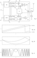
- the radio transceiver that is schematically represented in Figure 1 is a possible embodiment of the invention.
- the transceiver includes a baseband section 200 and a radiofrequency section 100.
- the transmitter includes a baseband modulator 150 that generates a baseband complex signal based on the digital data 152 at its input. This is then converted to the desired transmission frequency by the RF section 100, amplified by the power amplifier 120, and transmitted by the antenna.
- the signal is received on the other end of the radio link, it is processed by the receiving part of the transceiver of Figure 1 that comprises a low noise amplifier 160 followed to a down-conversion stage 170 that generates a baseband signal (which is again a complex signal represented, for example by two components I, Q) comprising a series of chirps, then treated by the baseband processor 180, whose function is the reverse of that of the modulator 150, and provides a reconstructed digital signal 182.
- a baseband signal which is again a complex signal represented, for example by two components I, Q
- the baseband processor 180 whose function is the reverse of that of the modulator 150, and provides a reconstructed digital signal 182.
- the signal may include also conjugate chirps that is, chirps that are complex conjugate of the base unmodulated chirp.
- conjugate chirps that is, chirps that are complex conjugate of the base unmodulated chirp.
- a modulation value of 0 is equivalent to the absence of modulation. Since N is a power of two, each modulated chirp can therefore be regarded as a symbol that encodes log 2 N bits in its cyclic shift can code. It is sometimes advantageous to limit the symbol constellation to a reduced set, defined for the purpose of this disclosure as a proper subset of the possible symbols.
- the information is encoded in the form of chirps that have one out of a plurality of possible cyclic shifts with respect to a predetermined base chirp, each cyclic shift corresponding to a possible modulation symbol or, otherwise said, the processor 180 needs to process a signal that comprises a plurality of frequency chirps that are cyclically time-shifted replicas of a base chirp profile, and extract a message that is encoded in the succession of said time-shifts.
- the signal transmitted and received by the invention are organised in frames that include a preamble and a data section, suitably encoded.
- the preamble and the data section comprise a series of chirps modulated and/or unmodulated, that allows the receiver to time-align its time reference with that of the transmitter, retrieve an element of information, perform an action, or execute a command.
- Figure 3 represents schematically, a frame structures that can be employed in various aspects of the present invention.
- the frame may include in the preamble a series of detect symbols 411, that allow the detection of an incoming signal in the receiver, different groups of synchronisation symbols 412, 413, 414, a header 415, and a payload 416 that includes the message intended for the destination node and may have variable length.
- the phase of the signal is continuous across symbol boundaries, a feature that will be referred to in the following as inter-symbol phase continuity.
- the function f ( t ) is symmetrical, and the signal has inter-symbol phase continuity.
- EP2449690 the structure of the signal described above allows the processor 180 in the receiver to align its time references with that of the transmitter, and the determination of the amount of cyclical shift imparted to each chirp.
- dechirping The operation of evaluating a time shift of a received chirp with respect to a local time reference may be referred to in the following as "dechirping", and can be carried out advantageously by a de-spreading step that involves multiplying the received chirp by a complex conjugate of a locally-generated base chirp, and a demodulation step that consists in performing a FFT of the de-spread signal.
- dechirping can be carried out advantageously by a de-spreading step that involves multiplying the received chirp by a complex conjugate of a locally-generated base chirp, and a demodulation step that consists in performing a FFT of the de-spread signal.
- Other manners of dechirping are however possible.
- the frames have a preamble including a detect sequence 411 of base (i.e. un-modulated, or with cyclic shift equal to zero) symbols.
- the detect sequence 411 is used in the receiver to detect the beginning of the signal and, preferably, perform a first synchronisation of its time reference with the time reference in the transmitter.
- the groups of symbols 412, 413, and 414 are required by the LoRa protocol and are used for synchronization but are not necessarily part of the present invention.
- the preamble may be followed by a message header 415 that informs the receiver on the format of the following data, and a payload 416 that is defined by the application. By demodulating the detect sequence, the receiver can determine a shift amount and adapt the frequency and phase of its clock with those of the sender, thus allowing the decoding of the following data.
- the modulator of the invention includes a differential encoding unit arranged for generating a series of shift, in which each possible value of the input symbol corresponds to a predetermined change in the series of differential-encoded symbols.
- Figure 5 illustrates a possible realization of the corresponding modulation chain: the digital stream that must be transmitted is processed by the forward error correction unit 205 that insert suitable error correction codes, then by the interleaver 207 and the Gray mapper 216.
- Block 219 transforms Gray encoded values into the desired modulation alphabet, also called modulation set. The alphabet may be complete or reduced.
- the complete modulation set includes as many symbols as here are possible cyclical shift from 0 to 2 SF - 1.
- the error rate in noisy condition can be reduced, albeit with a bandwidth reduction, choosing a reduced modulation set that does not include all the possible symbols.
- K should be a divisor of the symbol length; if the symbol length is a power of two, so should be K . This ensures that after the integration and modulo operation that are done in differential coding, the modulation set is unchanged.
- Blocks 225 and 228 symbolise the operations involved in the differential coding.
- the former 225 is a numerical integrator that accumulates the cyclical shifts generated by unit 219, and block 228 implements a modulo operation that generates a differential code 238 in 0,...2 SF - 1.
- the select/control block 230 allows switching between normal and differential code at will, also within a frame.
- the preambles are transmitted with non-differential modulations, while headers and payloads may be differentially encoded or not.
- the header is not differentially encoded and signal whether the payload is differentially encoded or not. In this way all receivers, whether they can receive differential modulation or not, can decode and understand the header. In this arrangement, the receiver needs not know in advance which modulation format is used.
- the selection block 230 sends to the chirp synthesizer 232 either the normal cyclical shifts 235, or the differentially encoded shifts 238, according to whether normal or differential modulation is desired. It resets also the integrator 225 when necessary, for example at transitions between normal and differential code.
- differential modulation is usually associate with a loss of about 3 dB, because the first demodulation operation is usually a difference between two symbols that have independent noise contributions. This state of affair can be mitigated by a special soft decoder.
- the soft output differential demodulator considers pairs of potential modulated values between the current symbol and the previous symbol. For each bit, independently of other bits, the pair with the maximum summed amplitude which corresponds to a '0' value is compared to the pair with the maximum summed amplitude corresponding to a '1' value. To reduce complexity to practical levels, only some modulation values are compared for each symbol, which correspond to the modulation values showing the highest amplitude after the FFT
- the soft differential demodulation method disclosed considers for each symbol m a limited number of possible modulation values, and, for each bit, consider the possible pair of modulation values in the current symbol and in the previous one.
- the method groups possible pair of modulation values in two sets according to the resulting value of that bit.
- the soft demodulated value is computed as the difference of the maximum summed magnitudes in the two sets.
- the inventors have found that such a soft demodulation method gives, for typical noise levels and equivalent error rates, a noise increase of 1 dB compared to non-differential soft demodulation.
- the number of modulation values considered remains reasonably low, 8 being a typical figure.
- the sensitivity can be increased, without augmenting the symbol length, by repeating symbols.
- the limit of the system is currently determined by detection, and synchronization tracking.
- the former limitation may be addressed by lengthening the preamble. Synchronization produces errors in the received message that cannot be recovered by FEC, however.
- the modulator of the invention may insert repetitions of the symbols in the transmitted frame to permit detection and correction of errors in the receiver.
- the repetition can be identical or, preferably, a repetition of a shifted symbol, by a cyclic shift that is known, or can be computed, by the receiver.
- LoRa modulation alphabet uses a regular distribution of cyclic shifts between 0 and 2 SF - 1. Some modulation values, for example those close to one half of the symbol length, are weaker than other for what resistance to noise and tracking are concerned. A shift introduced in symbol repetition may balance the distribution of these weaker values. For example, if the repetition level is 2, that is each symbol is transmitted twice, one transmission may be shifted systematically by symbol_length/2. If the repetition level is 4, the shifts may be ⁇ 0, symbol_length/4, symbol_length/2, symbol_length/4 ⁇ , and so on.
- Gray encoding is useful in detecting and correcting tracking errors. Due to the use of cyclic shifts in LoRa, the most common errors are those where a symbol is received and demodulated to a value that is shifted of ⁇ 1 from the original one. After Gray demapping, such errors translate into an arbitrary bit error.
- Differential modulation has a similar purpose as the Gray encoding, although it handles the errors differently: stable errors (a long constant error in timing or frequency at the receiver's side) are not repeated after the first occurrence; transition symbols - where the error first arises or ends - have, with Gray encoding, a random bit error. In fast-varying channels, this leads to high error rates.
- a reduced modulation set can help in these demanding cases, albeit at the cost of bandwidth. Gray encoding could be unnecessary.
- Figure 6 illustrates a simple schema of reduction of the modulation set in which one symbol out of four is used.
- the example relates to SF6 modulation, such that the possible symbol range from 0 to 63, or 1111 in binary. Only the symbols of the form 4 ⁇ p are used, while the others that are never generated, are indicated by "N/A".
- Figure 6 shows only a quarter of the possible 64 modulation values.
- Figure 7 illustrates another schema of reduction of the modulation set that combines advantageously with differential modulation where errors are not an integer number of samples or, in the Fourier domain, an integer number of FFT bins.
- the new mapping function transmits an additional bit (or an additional bit field) per symbol than the mapping function of figure 6 .
- the additional bit is denoted by B l
- the remaining SF-2 bits are denoted by B h . Only half of the symbols are used, in groups of two, and the remaining half is never used, but other schemes are possible. Compared to the 4 ⁇ p reduction scheme, there is an effective increase of one bit.
- the reduction scheme is arranged such that the B h field of bits is a "high reliability" field that can be decoded reliably and correctly also when there is an error of ⁇ 1 in the perceived cyclical shift, for example because the reduction scheme is organised in groups that encode the same value of B h .
- the B l bit is a "low reliability" field and is affected by such transitions.
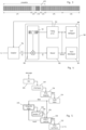
- Figure 8 illustrates, in schematic form, a possible realization of a modulation chain implementing the alternative mapping described above.
- the right branch comprising blocks 205, 207, 216, 219 corresponds to the processor disclosed above in relation to figure 5 , and its output is still available.
- the right branch includes a splitting operation 201, in which the message is split into two separate stream, one corresponding to (SF-2) bits and one to one bit.
- the data have preferably processed independently by insertion of error correction codes (block265) and interleaving (267).
- the forward error correction schemes for the B h branch and those for the B l branch are different and optimized in function of the different coding rates in the two branches.
- Block 289 symbolises the combination of B h and B l before the integration 225.
- the control unit 230 has therefore the choice between three possible data streams to transmit : the conventional data D(m) without differential encoding or parallel mapping, the differentially encoded data, and the data encoded in a reduced set with an additional B l bit, differentially encoded.
Landscapes
- Engineering & Computer Science (AREA)
- Computer Networks & Wireless Communication (AREA)
- Signal Processing (AREA)
- Digital Transmission Methods That Use Modulated Carrier Waves (AREA)
- Control Of Eletrric Generators (AREA)
- Electroluminescent Light Sources (AREA)
Claims (9)
- Verfahren zur Funkübermittlung, umfassend:Codierung einer digitalen Nachricht in eine Reihe von Eingangssymbolen, welche zu einem vorbestimmten Modulationssatz gehören, wobei jedes Symbol eine Vielzahl von Bits der digitalen Nachricht codiert;Erzeugen einer Reihe von differentiell kodierten Symbolen, wobei jeder mögliche Wert in der Reihe von Eingangssymbolen einer vorbestimmten Änderung in der Reihe der differentiell kodierten Symbole entspricht,Synthetisieren einer Reihe von modulierten Chirps, deren momentane Frequenzen gemäss einer von mehreren Funktionen variieren, die zyklische Verschiebungen einer Basis-Chirp-Funktion darstellen, wobei die zyklische Verschiebung eines Chirps den Wert eines entsprechenden Symbols in der Reihe von differentiell kodierten Symbolen darstellt.
- Verfahren gemäss dem vorhergehenden Anspruch, umfassend die folgenden Operationen an der digitalen Nachricht, in der Reihenfolge: Einfügen von Fehlerkorrekturcodes in die digitale Nachricht, Verschachtelung, Gray-Kodierung, Umwandlung der Gray-kodierten Werte in den Modulationssatz, Erzeugung des differential-kodierten Symbols.
- Verfahren gemäss einem der vorhergehenden Ansprüche, worin der Modulationssatz auf eine geeignete Teilmenge der möglichen Symbole reduziert wird.
- Verfahren gemäss dem vorhergehenden Anspruch, worin der reduzierte Modulationssatz ein Hauptbitfeld (Bh) und ein zusätzliches Bit oder Bitfeld (Bl) umfasst, worin das Reduzierungsschema derart ist, dass das Hauptbitfeld gegenüber Fehlern von ± 1 in der zyklischen Verschiebung robust ist.
- Verfahren gemäss dem vorhergehenden Anspruch, worin das Hauptfeld und das zusätzliche Bit oder Feld parallel verarbeitet werden.
- Verfahren gemäss irgendeinem der vorhergehenden Ansprüche, worin der Schritt vom Erzeugen einer Reihe von differentiell kodierten Symbolen selektiv deaktiviert werden kann, mit einem Schritt des Organisierens der Symbole in der Reihe von Eingangssymbolen in Rahmen, wobei ein Teil der Symbole in jedem Rahmen nicht differenziell kodiert sind.
- Verfahren gemäss dem vorhergehenden Anspruch, worin jeder Rahmen einen Präambelabschnitt zur Erkennung und Synchronisierung und einen Headerabschnitt zur Formatsignalisierung aufweist, welche nicht differenziell kodiert sind.
- Verfahren gemäss irgendeinem der vorhergehenden Ansprüche, mit einem Schritt des Ersetzens eines Eingangssymbols durch eine vorbestimmte Anzahl von Symbolen, welche vom Eingangssymbol durch eine vorbestimmte Abfolge von zyklischen Verschiebungen abgeleitet werden, welche die Nullverschiebung umfassen können.
- Funkgerät mit geringer Leistungsaufnahme und grosser Reichweite, welches einen Sendeabschnitt aufweist, derart konfiguriert, um das Verfahren gemäss irgendeinem der vorhergehenden Ansprüche durchzuführen.
Priority Applications (4)
| Application Number | Priority Date | Filing Date | Title |
|---|---|---|---|
| EP19215072.0A EP3836409B1 (de) | 2019-12-11 | 2019-12-11 | Funk mit geringer leistungsaufnahme und grosser reichweite |
| US17/114,619 US11245434B2 (en) | 2019-12-11 | 2020-12-08 | Low power long-range radio |
| CN202011435525.XA CN113055047B (zh) | 2019-12-11 | 2020-12-10 | 低功率长程无线电装置 |
| KR1020200173245A KR102444378B1 (ko) | 2019-12-11 | 2020-12-11 | 저 전력 장거리 무선 |
Applications Claiming Priority (1)
| Application Number | Priority Date | Filing Date | Title |
|---|---|---|---|
| EP19215072.0A EP3836409B1 (de) | 2019-12-11 | 2019-12-11 | Funk mit geringer leistungsaufnahme und grosser reichweite |
Publications (2)
| Publication Number | Publication Date |
|---|---|
| EP3836409A1 EP3836409A1 (de) | 2021-06-16 |
| EP3836409B1 true EP3836409B1 (de) | 2025-05-07 |
Family
ID=68848185
Family Applications (1)
| Application Number | Title | Priority Date | Filing Date |
|---|---|---|---|
| EP19215072.0A Active EP3836409B1 (de) | 2019-12-11 | 2019-12-11 | Funk mit geringer leistungsaufnahme und grosser reichweite |
Country Status (4)
| Country | Link |
|---|---|
| US (1) | US11245434B2 (de) |
| EP (1) | EP3836409B1 (de) |
| KR (1) | KR102444378B1 (de) |
| CN (1) | CN113055047B (de) |
Families Citing this family (6)
| Publication number | Priority date | Publication date | Assignee | Title |
|---|---|---|---|---|
| EP3836409B1 (de) * | 2019-12-11 | 2025-05-07 | Semtech Corporation | Funk mit geringer leistungsaufnahme und grosser reichweite |
| US12301276B2 (en) | 2021-02-05 | 2025-05-13 | Texas Instruments Incorporated | Frequency-division multiplexing |
| CN114301495B (zh) * | 2021-12-10 | 2023-05-19 | 河南工程学院 | 一种非相干LoRa系统下的软输出解调方法 |
| EP4293922A1 (de) * | 2022-06-17 | 2023-12-20 | Semtech Corporation | Sender, empfänger und verfahren für chirp-modulierte funksignale |
| CN115733899B (zh) * | 2022-10-18 | 2024-12-20 | 香港理工大学深圳研究院 | LoRa CSS信号并行调制的报文生成和解析方法 |
| CN116389208B (zh) * | 2023-03-10 | 2025-07-01 | 中国电子科技集团公司第三十八研究所 | 一种斜移键控-Chirp调制解调方法 |
Family Cites Families (17)
| Publication number | Priority date | Publication date | Assignee | Title |
|---|---|---|---|---|
| US7430257B1 (en) * | 1998-02-12 | 2008-09-30 | Lot 41 Acquisition Foundation, Llc | Multicarrier sub-layer for direct sequence channel and multiple-access coding |
| US6940893B1 (en) * | 1999-09-27 | 2005-09-06 | Telecommunications Research Laboratories | High-speed indoor wireless chirp spread spectrum data link |
| CN1213552C (zh) * | 2002-07-10 | 2005-08-03 | 华为技术有限公司 | 归零码超长距离传输方法及装置 |
| KR100654009B1 (ko) * | 2002-08-22 | 2006-12-04 | 아이트란 커뮤니케이션스 리미티드 | 차분 코드 시프트 키잉을 사용한 확산 스펙트럼 통신시스템 |
| US20070110140A1 (en) * | 2005-11-14 | 2007-05-17 | Ipwireless, Inc. | Automatic selection of coherent and noncoherent transmission in a wireless communication system |
| EP2278724A1 (de) | 2009-07-02 | 2011-01-26 | Nanoscale Labs | Kommunikationssystem |
| CN101793960B (zh) * | 2009-10-27 | 2013-12-11 | 北京邮电大学 | 具有啁啾特性的高精度动态门限目标监测方法 |
| GB2494146B (en) * | 2011-08-31 | 2018-05-09 | Qualcomm Technologies Int Ltd | Chirp communications |
| EP2763321B1 (de) | 2013-02-05 | 2020-04-08 | Semtech Corporation | Transmitter mit geringem Stromverbrauch und großer Reichweite |
| US8971379B2 (en) * | 2013-06-06 | 2015-03-03 | Cambridge Silicon Radio Limited | Chirp modulation |
| US9755818B2 (en) * | 2013-10-03 | 2017-09-05 | Qualcomm Incorporated | Method to enhance MIPI D-PHY link rate with minimal PHY changes and no protocol changes |
| CN108353176B (zh) * | 2015-09-24 | 2022-05-03 | Lg 电子株式会社 | 在图像编译系统中的基于amvr的图像编译方法和装置 |
| US10334519B2 (en) * | 2016-04-22 | 2019-06-25 | Qualcomm Incorporated | Chirp signal formats and techniques |
| EP3264622B1 (de) * | 2016-07-01 | 2019-03-27 | Semtech Corporation | Funkempfänger mit grosser reichweite, niedriger komplexität und niedriger leistung |
| EP3273607B1 (de) * | 2016-07-20 | 2023-01-18 | Semtech Corporation | Verfahren und system zur taktung und lokalisierung eines funksignals |
| FR3098066B1 (fr) * | 2019-06-25 | 2022-08-12 | Univ Bordeaux | Procédé de génération d’un signal comprenant une succession temporelle de chirps, procédé d’estimation de symboles véhiculés par un tel signal, produits programme d’ordinateur et dispositifs correspondants. |
| EP3836409B1 (de) * | 2019-12-11 | 2025-05-07 | Semtech Corporation | Funk mit geringer leistungsaufnahme und grosser reichweite |
-
2019
- 2019-12-11 EP EP19215072.0A patent/EP3836409B1/de active Active
-
2020
- 2020-12-08 US US17/114,619 patent/US11245434B2/en active Active
- 2020-12-10 CN CN202011435525.XA patent/CN113055047B/zh active Active
- 2020-12-11 KR KR1020200173245A patent/KR102444378B1/ko active Active
Also Published As
| Publication number | Publication date |
|---|---|
| KR102444378B1 (ko) | 2022-09-19 |
| US11245434B2 (en) | 2022-02-08 |
| KR20210074231A (ko) | 2021-06-21 |
| EP3836409A1 (de) | 2021-06-16 |
| US20210184724A1 (en) | 2021-06-17 |
| CN113055047B (zh) | 2023-01-13 |
| CN113055047A (zh) | 2021-06-29 |
Similar Documents
| Publication | Publication Date | Title |
|---|---|---|
| EP3836409B1 (de) | Funk mit geringer leistungsaufnahme und grosser reichweite | |
| CN103973626B (zh) | 低功率远程发射机 | |
| US8971379B2 (en) | Chirp modulation | |
| EP2573992A1 (de) | Effizientes Präambelformat für physikalische Schicht | |
| US20080310531A1 (en) | Robust channel estimation in communication systems | |
| CA2659665A1 (en) | Selective noise cancellation of a spread spectrum signal | |
| CN113475046B (zh) | 利用扎道夫-楚序列进行调制的方法和装置 | |
| US5546423A (en) | Spread spectrum digital transmission system using low-frequency pseudorandom encoding of the wanted information and spectrum spreading and compression method used in a system of this kind | |
| US8275017B2 (en) | Method of packet transmission and reception of quadrature amplitude modulated signals in a frequency hopping radio system | |
| HK40049364A (en) | Low power long-range radio device | |
| CN114465856A (zh) | 一种基于cdma体制的信号多进制调制方法、解调方法及设备 | |
| HK40049364B (en) | Low power long-range radio device | |
| RU2803188C2 (ru) | Способ и устройство для модуляции с последовательностями задова-чу | |
| JP3531827B1 (ja) | 直交周波数分割多重信号の送受信システム及び直交周波数分割多重信号の送受信方法 | |
| JP3531829B2 (ja) | 直交周波数分割多重信号の送受信システム及び直交周波数分割多重信号の送受信方法 | |
| JP3531830B1 (ja) | 直交周波数分割多重信号の送受信システム及び直交周波数分割多重信号の送受信方法 | |
| JP3531828B2 (ja) | 直交周波数分割多重信号の送受信システム及び直交周波数分割多重信号の送受信方法 | |
| JP3531823B2 (ja) | 直交周波数分割多重信号の送受信システム及び直交周波数分割多重信号の送受信方法 | |
| JP3531826B2 (ja) | 直交周波数分割多重信号の送受信システム及び直交周波数分割多重信号の送受信方法 | |
| JP3531824B2 (ja) | 直交周波数分割多重信号の送受信システム及び直交周波数分割多重信号の送受信方法 | |
| JP3531825B2 (ja) | 直交周波数分割多重信号の送受信システム及び直交周波数分割多重信号の送受信方法 | |
| JP3531834B1 (ja) | 直交周波数分割多重信号の送受信システム及び直交周波数分割多重信号の送受信方法 | |
| JP3531833B1 (ja) | 直交周波数分割多重信号の送受信システム及び直交周波数分割多重信号の送受信方法 | |
| JP3531832B2 (ja) | 直交周波数分割多重信号の送受信システム及び直交周波数分割多重信号の送受信方法 | |
| JP3818535B2 (ja) | 直交周波数分割多重信号の送受信システム及び直交周波数分割多重信号の送受信方法 |
Legal Events
| Date | Code | Title | Description |
|---|---|---|---|
| PUAI | Public reference made under article 153(3) epc to a published international application that has entered the european phase |
Free format text: ORIGINAL CODE: 0009012 |
|
| STAA | Information on the status of an ep patent application or granted ep patent |
Free format text: STATUS: THE APPLICATION HAS BEEN PUBLISHED |
|
| AK | Designated contracting states |
Kind code of ref document: A1 Designated state(s): AL AT BE BG CH CY CZ DE DK EE ES FI FR GB GR HR HU IE IS IT LI LT LU LV MC MK MT NL NO PL PT RO RS SE SI SK SM TR |
|
| STAA | Information on the status of an ep patent application or granted ep patent |
Free format text: STATUS: REQUEST FOR EXAMINATION WAS MADE |
|
| 17P | Request for examination filed |
Effective date: 20211215 |
|
| RBV | Designated contracting states (corrected) |
Designated state(s): AL AT BE BG CH CY CZ DE DK EE ES FI FR GB GR HR HU IE IS IT LI LT LU LV MC MK MT NL NO PL PT RO RS SE SI SK SM TR |
|
| STAA | Information on the status of an ep patent application or granted ep patent |
Free format text: STATUS: EXAMINATION IS IN PROGRESS |
|
| 17Q | First examination report despatched |
Effective date: 20230201 |
|
| P01 | Opt-out of the competence of the unified patent court (upc) registered |
Effective date: 20230530 |
|
| GRAP | Despatch of communication of intention to grant a patent |
Free format text: ORIGINAL CODE: EPIDOSNIGR1 |
|
| STAA | Information on the status of an ep patent application or granted ep patent |
Free format text: STATUS: GRANT OF PATENT IS INTENDED |
|
| INTG | Intention to grant announced |
Effective date: 20241204 |
|
| GRAS | Grant fee paid |
Free format text: ORIGINAL CODE: EPIDOSNIGR3 |
|
| GRAA | (expected) grant |
Free format text: ORIGINAL CODE: 0009210 |
|
| STAA | Information on the status of an ep patent application or granted ep patent |
Free format text: STATUS: THE PATENT HAS BEEN GRANTED |
|
| AK | Designated contracting states |
Kind code of ref document: B1 Designated state(s): AL AT BE BG CH CY CZ DE DK EE ES FI FR GB GR HR HU IE IS IT LI LT LU LV MC MK MT NL NO PL PT RO RS SE SI SK SM TR |
|
| REG | Reference to a national code |
Ref country code: GB Ref legal event code: FG4D |
|
| REG | Reference to a national code |
Ref country code: CH Ref legal event code: EP |
|
| REG | Reference to a national code |
Ref country code: DE Ref legal event code: R096 Ref document number: 602019069578 Country of ref document: DE |
|
| REG | Reference to a national code |
Ref country code: IE Ref legal event code: FG4D |
|
| REG | Reference to a national code |
Ref country code: NL Ref legal event code: MP Effective date: 20250507 |
|
| PG25 | Lapsed in a contracting state [announced via postgrant information from national office to epo] |
Ref country code: PT Free format text: LAPSE BECAUSE OF FAILURE TO SUBMIT A TRANSLATION OF THE DESCRIPTION OR TO PAY THE FEE WITHIN THE PRESCRIBED TIME-LIMIT Effective date: 20250908 Ref country code: FI Free format text: LAPSE BECAUSE OF FAILURE TO SUBMIT A TRANSLATION OF THE DESCRIPTION OR TO PAY THE FEE WITHIN THE PRESCRIBED TIME-LIMIT Effective date: 20250507 Ref country code: ES Free format text: LAPSE BECAUSE OF FAILURE TO SUBMIT A TRANSLATION OF THE DESCRIPTION OR TO PAY THE FEE WITHIN THE PRESCRIBED TIME-LIMIT Effective date: 20250507 |
|
| REG | Reference to a national code |
Ref country code: LT Ref legal event code: MG9D |
|
| PG25 | Lapsed in a contracting state [announced via postgrant information from national office to epo] |
Ref country code: NO Free format text: LAPSE BECAUSE OF FAILURE TO SUBMIT A TRANSLATION OF THE DESCRIPTION OR TO PAY THE FEE WITHIN THE PRESCRIBED TIME-LIMIT Effective date: 20250807 Ref country code: GR Free format text: LAPSE BECAUSE OF FAILURE TO SUBMIT A TRANSLATION OF THE DESCRIPTION OR TO PAY THE FEE WITHIN THE PRESCRIBED TIME-LIMIT Effective date: 20250808 |
|
| PG25 | Lapsed in a contracting state [announced via postgrant information from national office to epo] |
Ref country code: NL Free format text: LAPSE BECAUSE OF FAILURE TO SUBMIT A TRANSLATION OF THE DESCRIPTION OR TO PAY THE FEE WITHIN THE PRESCRIBED TIME-LIMIT Effective date: 20250507 Ref country code: PL Free format text: LAPSE BECAUSE OF FAILURE TO SUBMIT A TRANSLATION OF THE DESCRIPTION OR TO PAY THE FEE WITHIN THE PRESCRIBED TIME-LIMIT Effective date: 20250507 |
|
| REG | Reference to a national code |
Ref country code: AT Ref legal event code: MK05 Ref document number: 1793642 Country of ref document: AT Kind code of ref document: T Effective date: 20250507 |
|
| PG25 | Lapsed in a contracting state [announced via postgrant information from national office to epo] |
Ref country code: BG Free format text: LAPSE BECAUSE OF FAILURE TO SUBMIT A TRANSLATION OF THE DESCRIPTION OR TO PAY THE FEE WITHIN THE PRESCRIBED TIME-LIMIT Effective date: 20250507 |
|
| PG25 | Lapsed in a contracting state [announced via postgrant information from national office to epo] |
Ref country code: HR Free format text: LAPSE BECAUSE OF FAILURE TO SUBMIT A TRANSLATION OF THE DESCRIPTION OR TO PAY THE FEE WITHIN THE PRESCRIBED TIME-LIMIT Effective date: 20250507 |
|
| PG25 | Lapsed in a contracting state [announced via postgrant information from national office to epo] |
Ref country code: AT Free format text: LAPSE BECAUSE OF FAILURE TO SUBMIT A TRANSLATION OF THE DESCRIPTION OR TO PAY THE FEE WITHIN THE PRESCRIBED TIME-LIMIT Effective date: 20250507 |
|
| PG25 | Lapsed in a contracting state [announced via postgrant information from national office to epo] |
Ref country code: RS Free format text: LAPSE BECAUSE OF FAILURE TO SUBMIT A TRANSLATION OF THE DESCRIPTION OR TO PAY THE FEE WITHIN THE PRESCRIBED TIME-LIMIT Effective date: 20250807 |
|
| PG25 | Lapsed in a contracting state [announced via postgrant information from national office to epo] |
Ref country code: IS Free format text: LAPSE BECAUSE OF FAILURE TO SUBMIT A TRANSLATION OF THE DESCRIPTION OR TO PAY THE FEE WITHIN THE PRESCRIBED TIME-LIMIT Effective date: 20250907 |
|
| PG25 | Lapsed in a contracting state [announced via postgrant information from national office to epo] |
Ref country code: LV Free format text: LAPSE BECAUSE OF FAILURE TO SUBMIT A TRANSLATION OF THE DESCRIPTION OR TO PAY THE FEE WITHIN THE PRESCRIBED TIME-LIMIT Effective date: 20250507 |
|
| PGFP | Annual fee paid to national office [announced via postgrant information from national office to epo] |
Ref country code: GB Payment date: 20251229 Year of fee payment: 7 |
|
| PG25 | Lapsed in a contracting state [announced via postgrant information from national office to epo] |
Ref country code: SM Free format text: LAPSE BECAUSE OF FAILURE TO SUBMIT A TRANSLATION OF THE DESCRIPTION OR TO PAY THE FEE WITHIN THE PRESCRIBED TIME-LIMIT Effective date: 20250507 Ref country code: DK Free format text: LAPSE BECAUSE OF FAILURE TO SUBMIT A TRANSLATION OF THE DESCRIPTION OR TO PAY THE FEE WITHIN THE PRESCRIBED TIME-LIMIT Effective date: 20250507 |
|
| PGFP | Annual fee paid to national office [announced via postgrant information from national office to epo] |
Ref country code: FR Payment date: 20251226 Year of fee payment: 7 |
|
| PG25 | Lapsed in a contracting state [announced via postgrant information from national office to epo] |
Ref country code: CZ Free format text: LAPSE BECAUSE OF FAILURE TO SUBMIT A TRANSLATION OF THE DESCRIPTION OR TO PAY THE FEE WITHIN THE PRESCRIBED TIME-LIMIT Effective date: 20250507 |
|
| PG25 | Lapsed in a contracting state [announced via postgrant information from national office to epo] |
Ref country code: EE Free format text: LAPSE BECAUSE OF FAILURE TO SUBMIT A TRANSLATION OF THE DESCRIPTION OR TO PAY THE FEE WITHIN THE PRESCRIBED TIME-LIMIT Effective date: 20250507 |
|
| PG25 | Lapsed in a contracting state [announced via postgrant information from national office to epo] |
Ref country code: RO Free format text: LAPSE BECAUSE OF FAILURE TO SUBMIT A TRANSLATION OF THE DESCRIPTION OR TO PAY THE FEE WITHIN THE PRESCRIBED TIME-LIMIT Effective date: 20250507 Ref country code: SK Free format text: LAPSE BECAUSE OF FAILURE TO SUBMIT A TRANSLATION OF THE DESCRIPTION OR TO PAY THE FEE WITHIN THE PRESCRIBED TIME-LIMIT Effective date: 20250507 |
|
| PG25 | Lapsed in a contracting state [announced via postgrant information from national office to epo] |
Ref country code: IT Free format text: LAPSE BECAUSE OF FAILURE TO SUBMIT A TRANSLATION OF THE DESCRIPTION OR TO PAY THE FEE WITHIN THE PRESCRIBED TIME-LIMIT Effective date: 20250507 |
|
| REG | Reference to a national code |
Ref country code: DE Ref legal event code: R097 Ref document number: 602019069578 Country of ref document: DE |
|
| PLBE | No opposition filed within time limit |
Free format text: ORIGINAL CODE: 0009261 |
|
| STAA | Information on the status of an ep patent application or granted ep patent |
Free format text: STATUS: NO OPPOSITION FILED WITHIN TIME LIMIT |
|
| REG | Reference to a national code |
Ref country code: CH Ref legal event code: L10 Free format text: ST27 STATUS EVENT CODE: U-0-0-L10-L00 (AS PROVIDED BY THE NATIONAL OFFICE) Effective date: 20260318 |
|
| PGFP | Annual fee paid to national office [announced via postgrant information from national office to epo] |
Ref country code: DE Payment date: 20251229 Year of fee payment: 7 |
|
| 26N | No opposition filed |
Effective date: 20260210 |