EP3836483A1 - Modélisation thermique pour câbles transmettant des données et de la puissance - Google Patents
Modélisation thermique pour câbles transmettant des données et de la puissance Download PDFInfo
- Publication number
- EP3836483A1 EP3836483A1 EP21156406.7A EP21156406A EP3836483A1 EP 3836483 A1 EP3836483 A1 EP 3836483A1 EP 21156406 A EP21156406 A EP 21156406A EP 3836483 A1 EP3836483 A1 EP 3836483A1
- Authority
- EP
- European Patent Office
- Prior art keywords
- cables
- pse
- cable
- data
- thermal
- Prior art date
- Legal status (The legal status is an assumption and is not a legal conclusion. Google has not performed a legal analysis and makes no representation as to the accuracy of the status listed.)
- Granted
Links
Images



Classifications
-
- G—PHYSICS
- G01—MEASURING; TESTING
- G01K—MEASURING TEMPERATURE; MEASURING QUANTITY OF HEAT; THERMALLY-SENSITIVE ELEMENTS NOT OTHERWISE PROVIDED FOR
- G01K3/00—Thermometers giving results other than momentary value of temperature
- G01K3/005—Circuits arrangements for indicating a predetermined temperature
-
- H—ELECTRICITY
- H04—ELECTRIC COMMUNICATION TECHNIQUE
- H04L—TRANSMISSION OF DIGITAL INFORMATION, e.g. TELEGRAPHIC COMMUNICATION
- H04L12/00—Data switching networks
- H04L12/02—Details
- H04L12/10—Current supply arrangements
-
- G—PHYSICS
- G01—MEASURING; TESTING
- G01K—MEASURING TEMPERATURE; MEASURING QUANTITY OF HEAT; THERMALLY-SENSITIVE ELEMENTS NOT OTHERWISE PROVIDED FOR
- G01K13/00—Thermometers specially adapted for specific purposes
-
- G—PHYSICS
- G06—COMPUTING OR CALCULATING; COUNTING
- G06F—ELECTRIC DIGITAL DATA PROCESSING
- G06F30/00—Computer-aided design [CAD]
- G06F30/20—Design optimisation, verification or simulation
-
- H—ELECTRICITY
- H04—ELECTRIC COMMUNICATION TECHNIQUE
- H04L—TRANSMISSION OF DIGITAL INFORMATION, e.g. TELEGRAPHIC COMMUNICATION
- H04L12/00—Data switching networks
- H04L12/28—Data switching networks characterised by path configuration, e.g. LAN [Local Area Networks] or WAN [Wide Area Networks]
- H04L12/40—Bus networks
- H04L12/40006—Architecture of a communication node
- H04L12/40045—Details regarding the feeding of energy to the node from the bus
Definitions
- the present disclosure relates generally to communications networks, and more particularly, to thermal modeling for cables transmitting power and data communications.
- Communications cables that are used to deliver power and data simultaneously may encounter self-heating due to a combination of currents carried in the cables, how the cables are installed (e.g., cable bundling), and what type of cables are used.
- Heat generation in cable bundles is an issue that can greatly affect performance and cause damage to a cable plant.
- a method generally comprises receiving at a thermal modeling module, data from a Power Sourcing Equipment device (PSE) for cables extending from the PSE to Powered Devices (PDs), the cables configured to transmit power and data from the PSE to the PDs, calculating at the thermal modeling module, thermal characteristics for the cables based on the data, and identifying a thermal rise above a specified threshold at one of the cables.
- the data comprises real-time electrical data for the cables.
- an apparatus generally comprises an interface for receiving data from a Power Sourcing Equipment device (PSE) for cables extending from the PSE to Powered Devices (PDs), the cables configured to transmit power and data from the PSE to the PDs, the data comprising real-time electrical data for the cables, a processor for calculating thermal characteristics for the cables based on the data and identifying a thermal rise above a specified threshold at one of the cables, and memory for storing wire gauges and associated cable temperature ratings.
- PSE Power Sourcing Equipment device
- PDs Powered Devices
- logic is encoded on one or more non-transitory computer readable media for execution and when executed by a processor operable to process data from a Power Sourcing Equipment device (PSE) for cables extending from the PSE to Powered Devices (PDs), the cables configured to transmit power and data from the PSE to the PDs, the data comprising real-time electrical data for the cables, calculate thermal characteristics for the cables based on the data, and identify a thermal rise above a specified threshold at one of the cables.
- PSE Power Sourcing Equipment device
- PDs Powered Devices
- the embodiments described herein provide real-time thermal modeling in cables that are used to carry data and power simultaneously. Real-time measurements provide an accurate and up-to-date analysis of a cable plant health assessment.
- the embodiments may be used, for example, to identify power and thermal impact due to self-heating and provide alerts for possible over heat conditions.
- One or more embodiments may be used to limit power output based on the modeling or prevent modes that may result in unwanted cable behavior such as heat damage to the cable or other unintended consequences.
- one or more embodiments may collect cable heating factors (e.g., current carried in cable, cable type, cable installation, etc.) and use this data to model expected temperature rises and other health assessment characteristics in the cables to determine if the cable can handle the power level and if the integrity of the data carried across the cable is at risk.
- cable heating factors e.g., current carried in cable, cable type, cable installation, etc.
- the embodiments operate in the context of a data communications network including multiple network devices.
- the network may include any number of network devices in communication via any number of nodes (e.g., routers, switches, gateways, controllers, or other network devices), which facilitate passage of data within the network.
- nodes e.g., routers, switches, gateways, controllers, or other network devices
- the network devices may communicate over or be in communication with one or more networks (e.g., local area network (LAN), metropolitan area network (MAN), wide area network (WAN), virtual private network (VPN) (e.g., Ethernet virtual private network (EVPN), layer 2 virtual private network (L2VPN)), virtual local area network (VLAN), enterprise network, corporate network, data center, Internet, intranet, or any other network).
- networks e.g., local area network (LAN), metropolitan area network (MAN), wide area network (WAN), virtual private network (VPN) (e.g., Ethernet virtual private network (EVPN), layer 2 virtual private network (L2VPN)), virtual local area network (VLAN), enterprise network, corporate network, data center, Internet, intranet, or any other network).
- networks e.g., local area network (LAN), metropolitan area network (MAN), wide area network (WAN), virtual private network (VPN) (e.g., Ethernet virtual private network (EVPN), layer 2 virtual private network (L2VPN)
- EVPN Ethernet virtual private network
- the network may be configured for Power over Ethernet (PoE), Power over Fiber (PoF), or any other power over communications cable system that is used to pass electric power along with data to allow a single cable to provide both data connectivity and electric power to network devices such as wireless access points, IP (Internet Protocol) cameras, VoIP (Voice over IP) phones, video cameras, point-of-sale devices, security access control devices, residential devices, building automation, industrial automation, and many other devices.
- Signals may be exchanged among communications equipment and power transmitted from power sourcing equipment to powered devices.
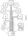
- the network may include a Power Sourcing Equipment device (PSE) 10 in communication with any number of Powered Devices (PDs) 12 via cables 14.
- the PSE may be a network device such as a switch that provides (sources) power on the cable 14.
- the PSE 10 may be configured to delivery power at one or more output levels (e.g., programmable PoE).
- the network may include any number of PSEs 10 in communication with any number of PDs 12.
- the PD 12 is powered by the PSE 10 and consumes energy.
- the cables 14 are configured to transmit both power and data from the PSE 10 to the PDs 12.
- the cables 14 may be formed from any material suitable to carry both power and data (e.g., copper, fiber).
- the cables 14 may comprise, for example Catx cable (e.g., category 5 twisted pair (e.g., four pair) Ethernet cabling) or any other type of cable.
- the cables 14 may extend between the PSE 10 and PDs 12 at a distance, for example, of 10 meters, 100 meters, or any other length.
- the cables 14 may be arranged in any configuration.
- the cables 14 may be bundled together in one or more groups 13 or stacked in one or more groups 15 as shown schematically in cross-section in Figure 1 . Any number of cables 14 may be bundled together.
- the cables 14 may have a round, flat, oval, or any other cross-sectional shape and may include any number or type of conductors (e.g., solid or stranded wires).
- the cables 14 may be bundled together at one location 16 while not bundled together at another location 17, for example.
- the cable 14 may be rated for one or more power levels, a maximum power level, a maximum temperature, or identified according to one or more categories indicating acceptable power level usage, for example.
- the cables 14 correspond to a standardized wire gauge system such as AWG (American Wire Gauge).
- AWG American Wire Gauge
- AWG provides data including diameter, area, resistance per length, ampacity (maximum amount of current a conductor can carry before sustaining immediate or progressive deterioration), and fusing current (how much current it takes to melt a wire in free air).
- Various other standards e.g., NEC (National Electrical Code), UL (Underwriters Laboratories) may be used to provide various requirements for the cable and cable system and provide temperature ratings or limits, or other information.
- This data may be stored in a thermal modeling system for reference in providing a cable thermal status, as described below.
- the cables 14 may encounter self-heating.
- a thermal modeling module 18 is configured to model the thermal impact due to self-heating.
- the thermal modeling module 18 is located at a network device 19, which may be located at a Network Operations Center (NOC), for example.
- the network device 19 may comprise, for example, a network management station, controller, computer, or any other device.
- the network device 19 is in communication with the PSE 10 and may also communicate with one or more PDs 12 directly or through the PSE.
- the thermal modeling module 18 (e.g., code, software, logic, firmware, application, client, appliance, hardware, device, element) may also be distributed across any number of network devices or operate in a cloud environment. Also, the thermal modeling module 18 or one or more components of the module may be located at the PSE 10, as shown in Figure 1 .
- the PSE 10 may measure one or more variables used for thermal modeling calculations at the PSE or at the network device 19.
- the PSE 10 may measure cable length using a TDR (Time Domain Reflectometer), output voltage at PSE, and current (e.g., for individual conductors).
- the PSE 10 may also collect intelligent PD available statistics for reporting input voltage at the PD.
- One or more calculations may be made at the PSE 10 or at the remote network device 19 based on measurements made at the PSE.
- the thermal modeling module 18 may collect data including, for example, cable AWG, real-time current carried in the conductors of the cables (nominal or maximum current), voltage (output at PSE, input at PD), cable length, cable segment length, number of PSE ports, cable proximity to other cables carrying currents that can act as localized heat sources, maximum expected ambient temperature where cables are routed, maximum temperature rating of the cable, temperature at PD, or any combination of this data or other data.
- Various measurements may be used to gather real-time data and user input may also be provided for one or more parameters (e.g., cable type, cable installation configuration, number of ports) if not available.
- the thermal modeling module 18 may use this data to determine the operational maximum power (maximum safe available power for delivery on the PSE port), thermal characteristics (real-time temperature rise in cables), overall health of an end-to-end cable 14, a bundle of those end-to-end cables, and a bundle encompassing bundles of cable bundles, and if a cable is safe for operation by the attached PD 12.
- the thermal modeling module 18 may calculate real-time localized heating in a cable plant and generate a cable plant risk assessment (e.g., spreadsheet, graphical image) and alarm states to minimize unsafe operation.
- the thermal modeling module 18 may provide an alarm state or syslog (system log) message, as well as prevent delivery of more power than is safely determined for a particular cable.
- the thermal modeling module 18 may warn a user of potential heating issues and power concerns that may compromise the cable plant, data integrity of the communications channel, and PD operation.
- the network device 19 may include a GUI (Graphical User Interface) II for receiving user input and presenting results of the thermal modeling to the user.
- GUI Graphic User Interface
- the GUI 11 may be used to display a risk assessment table or graphical image indicating the thermal rise, health status, or other information about the cables and cable plant.
- the network devices and topology shown in Figure 1 and described above are only examples and the embodiments described herein may be implemented in networks comprising different network topologies or network devices, or using different protocols or cables, without departing from the scope of the embodiments.
- the network may comprise any number or type of network devices that facilitate passage of data over the network (e.g., routers, switches, gateways, controllers), network elements that operate as endpoints or hosts (e.g., servers, virtual machines, clients), and any number of network sites or domains in communication with any number of networks.
- network nodes may be used in any suitable network topology, which may include any number of servers, virtual machines, switches, routers, or other nodes interconnected to form a large and complex network, which may include cloud or fog computing.
- Nodes may be coupled to other nodes or networks through one or more interfaces employing any suitable wired or wireless connection, which provides a viable pathway for electronic communications.
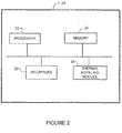
- Figure 2 illustrates an example of a network device 20 that may be used to implement the embodiments described herein.
- the network device 20 is a programmable machine that may be implemented in hardware, software, or any combination thereof.
- the network device 20 includes one or more processors 22, memory 24, network interface (port) 26, and thermal modeling module 28.
- Memory 24 may be a volatile memory or non-volatile storage, which stores various applications, operating systems, modules, and data for execution and use by the processor 22.
- components of the thermal modeling module 28 e.g., code, logic, firmware, etc.
- Memory 24 may also store manually input data (e.g., wire gauges and associated cable temperature ratings, measurements, calculated data, or other data, tables, or graphs.
- the network device 20 may include any number of memory components.
- Logic may be encoded in one or more tangible media for execution by the processor 22.
- the processor 22 may execute codes stored in a computer-readable medium such as memory 24.
- the computer-readable medium may be, for example, electronic (e.g., RAM (random access memory), ROM (read-only memory), EPROM (erasable programmable read-only memory)), magnetic, optical (e.g., CD, DVD), electromagnetic, semiconductor technology, or any other suitable medium.
- the computer-readable medium comprises a non-transitory computer-readable medium.
- Logic may be used to perform one or more functions described below with respect to the flowchart of Figure 3 .
- the network device 20 may include any number of processors 22.
- the network interface 26 may comprise any number of interfaces (linecards, ports) for receiving data or transmitting data to other devices.
- the interface may be, for example, an interface at the PSE 10 for transmitting power and data to the PD 12, an interface at the PSE for transmitting measurements, data, or risk assessment information to the network device 19, or an internal interface at the PSE 10 for transmitting data to the thermal modeling module 18 ( Figures 1 and 2 ).
- the network interface 26 may include, for example, an Ethernet interface for connection to a computer or network.
- the interface 26 may be configured for PoE, PoF, or similar operation.
- network device 20 shown in Figure 2 and described above is only an example and that different configurations of network devices may be used.
- the network device 20 may further include any suitable combination of hardware, software, algorithms, processors, devices, components, or elements operable to facilitate the capabilities described herein.
- FIG 3 is a flowchart illustrating an overview of a process for modeling thermal characteristics of cables used to transmit power and data, in accordance with one embodiment.
- the thermal modeling module 18 receives real-time electrical data (e.g., real-time measurements of relevant parameters) from the PSE 10 ( Figures 1 and 3 ).
- data is extracted from the PSE 10, which may include data from the PDs 12.
- User input may be received if an intelligent PD is not available.
- the thermal modeling module 18 identifies cable adjacencies and characteristics (step 32).
- the PSE 10 may use a TDR to determine the cable length at each port.
- the thermal modeling module 18 may use voltage, current, and cable length to determine wire gauge using a calculated resistance.
- the wire gauge may be provided by user input.
- cable adjacencies e.g., arrangement of cables within a bundle, bundle size
- E field pulse field strength
- the thermal modeling module 18 may use the wire gauge data, cable adjacencies, and current, voltage, and power data to calculate thermal characteristics for the cables (step 34).
- the thermal characteristics may include, for example, thermal rise, maximum power, and overall end-to-end cable health.
- the thermal modeling module 18 may take action to reduce the risk of unsafe operation at the cable (step 38). This may include, for example, identifying the cable in a risk assessment table, graphical image, alert, alarm, message, or other indication presented to a user, or preventing operation of the port connected to the cable.
- the thermal modeling module 18 may, for example, generate a table or image to indicate cable health for a selected power level and environment for a cable or bundle of cables, as well as generate alarm states (e.g., lights) and messages (e.g., syslog).
- the thermal rise may refer to a specific temperature, delta temperature, change in temperature (e.g., percent or increase above a baseline temperature), or a rise in temperature over a period of time.
- the following provides examples for determining wire gauge, bundle size, and cable adjacencies, and presenting data and thermal modeling results to a user.
- the user may enter the basic wire gauge for the assessment calculations if there is not an intelligent PD to provide V_in.
- FIG 4 illustrates an example of a PSE 40 that may be used to provide measurements for use in automatically calculating cable adjacency.
- the PSE 40 includes two PHY (circuitry for physical layer functions) each having a SerDes 41 (Serializer/Deserializer), a signal receiver 44, and a signal generator 46.
- the PSE 40 may comprise any number of ports and corresponding components.
- a 1MHz (or any other frequency) pulse is transmitted by the signal generator 46.
- the pulse is used to automatically determine cable to cable proximity by calculating a measured field strength (E Field 48) at the receiver 44.
- the pulse may be used to track a cable tied to a particular port or switch within a cable bundle referenced to the transmitting port.
- the pulse may be used, for example within a switch or router during bring up.
- the 1MHz pulse cannot be used to determine cable proximity between switches in a network or in a situation wherein a data center is running production traffic and a new switch or new cable plant is added.
- a packet pulse generator may be used as shown in Figure 5 .
- FIG. 5 illustrates a plurality of PSEs 50a, 50b, 50c, 50d, 50e, with one or more PSEs configured as a packet pulse generator for use in automatically calculating cable adjacency and bundle size determination, in accordance with one embodiment.
- the PSE includes a SerDes 51, signal receiver 54 and signal generator 56, as previously described.
- the PSEs may communicate with one another over an Ethernet command port communications plane or over a data plane, for example.
- the packet pulse generator is a specific packet type (packet 55 in Figure 5 ) transmitted instead of idle packets and with a higher energy content achieved by increasing the transmitted signal.
- the packet 55 is detected and the receiver 54 calculates the cable to cable distance based on the field strength (E Field 58).
- PSE 50b generates the packet 55 and the field strength 58 is measured by PSE 50a.
- the packet pulse generator allows the equipment and cable plant to change over time with constant
- the packet pulse generator carries switch IP (Internet Protocol) address and port ID (identifier) so that adjacent switches in the data center can identify where the packet is sourced from and return the received calculation for each port on the switch receiving or recognizing the packet.
- the packet 55 includes the source equipment IP address (e.g., IP address for Ethernet console port or command control panel), source equipment definition (e.g., what kind of switching or routing equipment), source port (e.g., port number, port power capability, port speed capability), signal data definition (e.g., data packet type (FFFF0000, FF00, AA55, etc.)), and data (e.g., as many bytes as possible of the signal data definition).
- source equipment IP address e.g., IP address for Ethernet console port or command control panel
- source equipment definition e.g., what kind of switching or routing equipment
- source port e.g., port number, port power capability, port speed capability
- signal data definition e.g., data packet type (FFFF0000, FF00, AA55
- the pulsing and high frequency tests described above may be used to detect cable architecture (e.g., cable bundling, cable adjacency, bundle size) and basic dielectric calculations may be used to determine cable insulation type.
- cable architecture e.g., cable bundling, cable adjacency, bundle size
- basic dielectric calculations may be used to determine cable insulation type.
- a source wire pulse may be transmitted on one port and the pulse field strength measured on 95 ports. This process may be repeated through 96 ports or a fewer number of ports.
- a pulse may be sent on only a portion of the ports until an arrangement of the cables is identified.
- the cable bundling may be determined by using field strength measurements to determine cable location and cable adjacency. For example, finite element analysis and a convergence algorithm may be used to determine cable-to-cable proximity.
- the pulse strength may be increased on a closest pair to determine if a change indicates shielded or not shielded.
- the measured field strength will increase with a smaller factor with a shielded cable.
- An algorithm output may be used to determine the proximity of cables and build a table.
- both the 1MHz pulse and packet pulse generator may be used to determine cable adjacencies.
- the 1MHz pulse may be used during bring up and the packet pulse generator used for periodic updates.
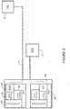
- FIG. 6 illustrates an embodiment that may be used to determine cable length and health.
- PSE 60 includes a SerDes 61, signal receiver 64, TDR (Time Domain Reflectometer) 65, and signal generator 66.
- the TDR 65 may be used to determine the cable length for any port, which may be used to calculate wire gauge (e.g., AWG). If the voltage at the PD 12 is known by the PSE 60, this may be used in conjunction with cable length to determine cable AWG per port, as previously described.
- the TDR 65 may also be used to evaluate and determine the cable segments and connection quality. When the PHY detects a cable is connected, a TDR process may be performed to determine the basic cable layout.
- TDR data may provide, for example, cable length and maximum loss, number of cable segments (length of cable segments and loss per segment, connector count and loss), and identification of cable anomalies.
- a cable health assessment may be performed based on losses in the cable. The health assessment may determine the relative loss at each segment (conductor in a particular length of cable) and at each segment point (e.g., RJ45 connector or other type of connector). Using the defined wire gauge calculations, each cable segment in the entire cable length may be evaluated for maximum conductor current. Each connector may be evaluated for its ability to handle the port conductor current. The health assessment along with overall wire gauge calculations may be used to determine the maximum conductor current of an end-to-end cable. In one embodiment, transmit and receive equalization sequences or channel operating margin may be used in place of TDR.
- tables 70, 80, and 90 may be created from automatically generated data, manually entered data, and calculations.
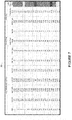
- the table 70 shown in Figure 7 is based on smart PDs, which are configured to measure their input port voltage.
- the table 80 shown in Figure 8 is based on a Vpd calculated by the PSE.
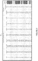
- the table 90 shown in Figure 9 is based on smart PDs and automatically gathered cable bundle information.
- the table 70 includes Vpse (V_out), Iport (I_individual_cable), Pport (power_port), Vpd (V_in), TDR (length), Cable AWG (wire gauge), Cable Temp Rating, Bundle (bundle containing cable (e.g., A, B)), Pcable (calculated power dissipated by (or in) the cable), Thermal Rise, and Cable Thermal Status.
- the PSE 10 measures Iport, Vpse, Pport, and TDR (to determine cable length) ( Figures 1 and 7 ).
- the PSE 10 measures the real-time current in the cable and the real-time output voltage at the PSE.
- the PD 12 measures its port voltage and sends it to the PSE 10 via Layer 2.
- the user may input the cable temperature rating for each AWG, and the bundle in which the cable is located. This information may be input at the GUI 11 at the network operations center device 19, for example, and stored at the thermal modeling module 18.
- the thermal modeling module 18 calculates Pcable based on a combination of Iport and Vpd. The thermal rise may be calculated based on Iport and bundle size.
- the thermal rise calculations may take into account, for example, cable characteristics (e.g., gauge, area, length, material, insulation type), location (e.g., cable adjacency, bundle location, bundle size), electrical characteristics (e.g., current, voltage, resistance, power), thermal properties (e.g., conductive and convective properties of cable, environment (air gaps, bundling contact, maximum expected ambient temperature at location of cable routing)), or any combination of these or other variables.
- cable characteristics e.g., gauge, area, length, material, insulation type
- location e.g., cable adjacency, bundle location, bundle size
- electrical characteristics e.g., current, voltage, resistance, power
- thermal properties e.g., conductive and convective properties of cable, environment (air gaps, bundling contact, maximum expected ambient temperature at location of cable routing)
- the cable thermal status is based on the calculated thermal rise and maximum temperature rating of the cable and may be represented, for example, as a color (e.g., green (safe operating condition), yellow (approaching unsafe operating condition), red (unsafe operating condition)) based on a specified limit or threshold.
- the threshold may be based on standard temperature limits for the cable or may be user defined.
- Cable health may be determined based on an expected Pcable based on Iport, Vport, and TDR as compared to Pcable calculated using Vpd.
- the table 80 shows an example of a risk assessment table for a system in which the PDs are not configured to measure port voltage and provide Vpd.
- the Vpd column in table 80 is moved from the automatically gathered data (in table 70) to the calculated data.
- the PSE 10 measures Iport, Vport, Pport, and TDR (to measure cable length).
- a user may input AWG of cable conductors, the cable temperature rating, and the bundle containing the cable.
- the thermal modeling module 18 (at PSE or other network device 19) may calculate: Vpd based on Iport, Vport, cable length, and AWG; Pcable based on combination of Iport and Vpd; and thermal rise based on Iport and bundle size.
- the cable thermal status is based on thermal rise and may be indicated as green, yellow, or red, as described above. The cable health cannot be determined without the help of the PD.
- the table 90 in Figure 9 illustrates an automated case in which the smart PDs provide the port voltage (Vpd) and the PSE uses a signal or packet pulse (as described above with respect to Figures 4 and 5 ) to automatically determine cable bundle configuration.
- data including Vpse, Iport, Pport, Vpd, TDR, Cable AWG, and Bundle information is automatically gathered.
- the cable power (Pcable) and resulting thermal rise are calculated.
- a cable thermal status column is provided to indicate the health of the cable based on thermal rise thresholds.
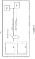
- Figure 10 illustrates an example of a customer risk assessment graphical image 100.
- an indication is provided for each cable with respect to the risk/health assessment table.
- the graphical view 100 shown in Figure 10 may be available on a customer screen (e.g., GUI 11 at network operations center device 19 in Figure 1 ) or on an equipment display screen.
- the tables 70, 80, 90 shown in Figures 7 , 8 , and 9 and the graphical image 100 shown in Figure 10 are only examples and that different data, more or less data, or any combination or presentation of data may be provided in the tables or shown in the graphical view.
- a GUI may allow a user to select how much information or details are presented and how they are presented (e.g., table, image). Also, the user may select to view only a portion of a cable plant, one or more cable plants, or only cables or cable plants with thermal or power issues.
- the thermal modeling module 18 may transmit one or more alerts (alarm. message, syslog, etc.) when a specified threshold has been reached (e.g., thermal rise above a specified limit, maximum current or power exceeded in one or more cables).
- a specified threshold e.g., thermal rise above a specified limit, maximum current or power exceeded in one or more cables.
- the thermal modeling module 18 may determine or user input provided to define appropriate thresholds for allowable temperature rise in a cable for safe operation per port.
- a red cable thermal status may prevent the port from operating and a yellow cable thermal status may only allow the port to operate with user intervention.
- the GUI may allow for a red override. The user may set the green/yellow/red threshold as appropriate for their cable plant configuration.
- the thermal modeling module 18 may generate a flag based on worst case PD classification current.
- the alarm conditions may include, for example, a strict mode in which the PSE 10 monitors real-time PD currents and enforces a current limit (i.e., shuts down port when current limit is exceeded), and a non-strict mode in which the PSE monitors real-time PD currents and generates an alarm when a current limit is exceeded.
- the alarm and assessment information may be displayed, for example, on a system display panel or customer interface and provide an indication that attention is needed (e.g., blue attention LED (Light Emitting Diode), syslog message sent through the Ethernet control interface port to the network operations center).
- one or more embodiments may be used to prevent the unwanted heating of cables (e.g., individual cables, bundle of cables) in communications cables where power is delivered over the cables to a powered device.
- the calculations may be done at installation and continued in real-time during idle packet transfer of the communications circuit, for example.
- Alarm conditions, attention lights, LCD (Liquid Crystal Display), and messaging may be used to alert the end user in the event an unwanted amount of power beyond the ability of the cable and cable environment is requested by the PD.
- the PSE port may automatically limit the power available for delivery based on the ability of the cable to safely deliver the required current, and thereby prevent serious damage to the cable plant, building, or user.
- the embodiments may be used, for example, by network engineers who manage networks with a significant deployment of PoE or PoF powered devices to provide a warning of deployment scenarios where the self-heating of cables could jeopardize the data integrity of the cables.
- the system may be used for long term planning in a cable plant, for example.
- One or more embodiments allow a network engineer to simply review the cable plant health assessment, which provides a more accurate assessment than may be provided with visual inspection and also saves a significant amount of time.
Landscapes
- Engineering & Computer Science (AREA)
- Physics & Mathematics (AREA)
- Computer Networks & Wireless Communication (AREA)
- Signal Processing (AREA)
- General Physics & Mathematics (AREA)
- Theoretical Computer Science (AREA)
- Computer Hardware Design (AREA)
- Evolutionary Computation (AREA)
- Geometry (AREA)
- General Engineering & Computer Science (AREA)
- Remote Monitoring And Control Of Power-Distribution Networks (AREA)
- Laying Of Electric Cables Or Lines Outside (AREA)
Applications Claiming Priority (3)
| Application Number | Priority Date | Filing Date | Title |
|---|---|---|---|
| US15/604,344 US10809134B2 (en) | 2017-05-24 | 2017-05-24 | Thermal modeling for cables transmitting data and power |
| EP18731242.6A EP3632039B1 (fr) | 2017-05-24 | 2018-05-11 | Modélisation thermique pour câbles transmettant des données et de la puissance |
| PCT/US2018/032250 WO2018217476A1 (fr) | 2017-05-24 | 2018-05-11 | Modélisation thermique pour câbles transmettant des données et de la puissance |
Related Parent Applications (2)
| Application Number | Title | Priority Date | Filing Date |
|---|---|---|---|
| EP18731242.6A Division-Into EP3632039B1 (fr) | 2017-05-24 | 2018-05-11 | Modélisation thermique pour câbles transmettant des données et de la puissance |
| EP18731242.6A Division EP3632039B1 (fr) | 2017-05-24 | 2018-05-11 | Modélisation thermique pour câbles transmettant des données et de la puissance |
Publications (2)
| Publication Number | Publication Date |
|---|---|
| EP3836483A1 true EP3836483A1 (fr) | 2021-06-16 |
| EP3836483B1 EP3836483B1 (fr) | 2023-03-01 |
Family
ID=62599683
Family Applications (2)
| Application Number | Title | Priority Date | Filing Date |
|---|---|---|---|
| EP18731242.6A Active EP3632039B1 (fr) | 2017-05-24 | 2018-05-11 | Modélisation thermique pour câbles transmettant des données et de la puissance |
| EP21156406.7A Active EP3836483B1 (fr) | 2017-05-24 | 2018-05-11 | Modélisation thermique pour câbles transmettant des données et de la puissance |
Family Applications Before (1)
| Application Number | Title | Priority Date | Filing Date |
|---|---|---|---|
| EP18731242.6A Active EP3632039B1 (fr) | 2017-05-24 | 2018-05-11 | Modélisation thermique pour câbles transmettant des données et de la puissance |
Country Status (5)
| Country | Link |
|---|---|
| US (5) | US10809134B2 (fr) |
| EP (2) | EP3632039B1 (fr) |
| CN (1) | CN110663219B (fr) |
| CA (1) | CA3063101C (fr) |
| WO (1) | WO2018217476A1 (fr) |
Cited By (1)
| Publication number | Priority date | Publication date | Assignee | Title |
|---|---|---|---|---|
| CN114039802A (zh) * | 2021-09-18 | 2022-02-11 | 深圳市联洲国际技术有限公司 | 数据处理方法、扩展电路、系统、设备及存储介质 |
Families Citing this family (27)
| Publication number | Priority date | Publication date | Assignee | Title |
|---|---|---|---|---|
| US11054457B2 (en) | 2017-05-24 | 2021-07-06 | Cisco Technology, Inc. | Safety monitoring for cables transmitting data and power |
| US10809134B2 (en) * | 2017-05-24 | 2020-10-20 | Cisco Technology, Inc. | Thermal modeling for cables transmitting data and power |
| WO2018234101A1 (fr) * | 2017-06-22 | 2018-12-27 | Philips Lighting Holding B.V. | Réseau poe renforcé par des fibres optiques |
| US11093012B2 (en) | 2018-03-02 | 2021-08-17 | Cisco Technology, Inc. | Combined power, data, and cooling delivery in a communications network |
| US10281513B1 (en) | 2018-03-09 | 2019-05-07 | Cisco Technology, Inc. | Verification of cable application and reduced load cable removal in power over communications systems |
| JP6992737B2 (ja) * | 2018-12-14 | 2022-01-13 | オムロン株式会社 | 設計支援装置及び設計支援プログラム |
| US11061456B2 (en) | 2019-01-23 | 2021-07-13 | Cisco Technology, Inc. | Transmission of pulse power and data over a wire pair |
| US10790997B2 (en) | 2019-01-23 | 2020-09-29 | Cisco Technology, Inc. | Transmission of pulse power and data in a communications network |
| US10680836B1 (en) | 2019-02-25 | 2020-06-09 | Cisco Technology, Inc. | Virtualized chassis with power-over-Ethernet for networking applications |
| US11456883B2 (en) | 2019-03-13 | 2022-09-27 | Cisco Technology, Inc. | Multiple phase pulse power in a network communications system |
| US11159335B2 (en) * | 2019-08-06 | 2021-10-26 | Cisco Technology, Inc. | Controller-based management of noncompliant power over ethernet devices |
| US12126399B2 (en) | 2019-11-01 | 2024-10-22 | Cisco Technology, Inc. | Fault managed power with dynamic and adaptive fault sensor |
| US11063630B2 (en) | 2019-11-01 | 2021-07-13 | Cisco Technology, Inc. | Initialization and synchronization for pulse power in a network system |
| US11252811B2 (en) | 2020-01-15 | 2022-02-15 | Cisco Technology, Inc. | Power distribution from point-of-load with cooling |
| US11853138B2 (en) | 2020-01-17 | 2023-12-26 | Cisco Technology, Inc. | Modular power controller |
| US11543844B2 (en) | 2020-02-25 | 2023-01-03 | Cisco Technology, Inc. | Method and apparatus for transmitting power and data in a multi-drop architecture |
| US11438183B2 (en) | 2020-02-25 | 2022-09-06 | Cisco Technology, Inc. | Power adapter for power supply unit |
| US11637497B2 (en) | 2020-02-28 | 2023-04-25 | Cisco Technology, Inc. | Multi-phase pulse power short reach distribution |
| US11307368B2 (en) | 2020-04-07 | 2022-04-19 | Cisco Technology, Inc. | Integration of power and optics through cold plates for delivery to electronic and photonic integrated circuits |
| US11320610B2 (en) | 2020-04-07 | 2022-05-03 | Cisco Technology, Inc. | Integration of power and optics through cold plate for delivery to electronic and photonic integrated circuits |
| EP4172581B1 (fr) * | 2020-06-25 | 2025-08-20 | SCHEMMANN, Marcel | Gestion de charge de courant pour régulation de température dans un conduit de câble |
| US11582048B2 (en) | 2020-07-17 | 2023-02-14 | Cisco Technology, Inc. | Bi-directional power over ethernet for digital building applications |
| US11708002B2 (en) | 2020-08-03 | 2023-07-25 | Cisco Technology, Inc. | Power distribution and communications for electric vehicle |
| US11745613B2 (en) | 2020-08-26 | 2023-09-05 | Cisco Technology, Inc. | System and method for electric vehicle charging and security |
| EP4339913A3 (fr) * | 2022-09-16 | 2024-05-29 | Honeywell International Inc. | Procédés, appareils et systèmes de détection d'incendie par infrarouge |
| EP4689903A2 (fr) * | 2023-04-04 | 2026-02-11 | Ubiquiti Inc. | Éclairage à del rj45 intelligent |
| US12443251B2 (en) | 2023-07-27 | 2025-10-14 | Cisco Technology, Inc. | Fault managed power in a power distribution unit |
Citations (4)
| Publication number | Priority date | Publication date | Assignee | Title |
|---|---|---|---|---|
| EP1936861A1 (fr) * | 2006-12-19 | 2008-06-25 | Broadcom Corporation | Système et procédé de regulation du courant alimenté vers un dispositif électrique à base de caracteristiques de câble |
| WO2010053542A2 (fr) * | 2008-11-08 | 2010-05-14 | Sensortran, Inc. | Système et procédé de détermination de caractéristiques de câbles de puissance à l'aide de systèmes de détection de température distribués |
| US20120317426A1 (en) * | 2011-06-09 | 2012-12-13 | Andrew Llc | Distributed antenna system using power-over-ethernet |
| EP2693688A1 (fr) * | 2012-08-03 | 2014-02-05 | Broadcom Corporation | Diagnostics de déséquilibre de câble entre canaux qui comprennent des paires de câbles pour transmission de puissance sur Ethernet |
Family Cites Families (246)
| Publication number | Priority date | Publication date | Assignee | Title |
|---|---|---|---|---|
| US3335324A (en) | 1965-10-06 | 1967-08-08 | Westinghouse Air Brake Co | Fail-safe continuous ground monitoring circuit |
| US3962529A (en) | 1970-10-07 | 1976-06-08 | Sumitomo Electric Industries, Ltd. | Evaporative cooling power cable line |
| EP0191482B1 (fr) | 1985-02-12 | 1990-07-25 | Hitachi Metals, Ltd. | Convertisseur courant continu/courant continu |
| US4803331A (en) | 1987-01-28 | 1989-02-07 | Cohen Robert K | Power control and line voltage monitor/compensator for resistance spot welding machines |
| US4794229A (en) * | 1987-04-24 | 1988-12-27 | Thermon Manufacturing Company | Flexible, elongated thermistor heating cable |
| US4859834A (en) * | 1988-06-15 | 1989-08-22 | Letco Management Company, Inc. | Power controller for heat tracing cable which responds to ambient temperature |
| US4997388A (en) | 1989-08-28 | 1991-03-05 | Amp Incorporated | Electrical tap connector |
| US5827267A (en) | 1992-02-18 | 1998-10-27 | Angeion Corporation | Cooled multi-fiber medical connector |
| US5652893A (en) | 1994-12-13 | 1997-07-29 | 3Com Corporation | Switching hub intelligent power management |
| US5602387A (en) * | 1995-06-26 | 1997-02-11 | The United States Of America As Represented By The Secretary Of The Air Force | Method of protecting an RF receiver in a hostile electromagnetic environment |
| US6470405B2 (en) | 1995-10-19 | 2002-10-22 | Rambus Inc. | Protocol for communication with dynamic memory |
| US6931183B2 (en) | 1996-03-29 | 2005-08-16 | Dominion Lasercom, Inc. | Hybrid electro-optic cable for free space laser antennas |
| US7237036B2 (en) | 1997-10-14 | 2007-06-26 | Alacritech, Inc. | Fast-path apparatus for receiving data corresponding a TCP connection |
| US6220955B1 (en) | 1998-02-17 | 2001-04-24 | John G. Posa | Combination power and cooling cable |
| US6826368B1 (en) | 1998-10-20 | 2004-11-30 | Lucent Technologies Inc. | Wavelength division multiplexing (WDM) with multi-frequency lasers and optical couplers |
| ATE297623T1 (de) | 1998-10-30 | 2005-06-15 | Broadcom Corp | Internet-gigabit-ethernet-sender-architektur |
| US6643566B1 (en) | 1999-01-12 | 2003-11-04 | Powerdsine Ltd. | System for power delivery over data communication cabling infrastructure |
| US6008631A (en) | 1999-03-18 | 1999-12-28 | International Business Machines Corporation | Synchronous voltage converter |
| US6636538B1 (en) | 1999-03-29 | 2003-10-21 | Cutting Edge Optronics, Inc. | Laser diode packaging |
| US20030214800A1 (en) | 1999-07-15 | 2003-11-20 | Dibene Joseph Ted | System and method for processor power delivery and thermal management |
| US6520807B2 (en) | 1999-11-12 | 2003-02-18 | Fci Americas Technology, Inc. | Electrical connector system with low cross-talk |
| US6400579B2 (en) | 2000-03-24 | 2002-06-04 | Slobodan Cuk | Lossless switching DC to DC converter with DC transformer |
| JP3830726B2 (ja) | 2000-04-26 | 2006-10-11 | 松下電器産業株式会社 | 熱伝導基板とその製造方法およびパワーモジュール |
| US6379157B1 (en) | 2000-08-18 | 2002-04-30 | Leviton Manufacturing Co., Inc. | Communication connector with inductive compensation |
| US6734784B1 (en) | 2000-09-06 | 2004-05-11 | Marshall E. Lester | Zero crossing based powerline pulse position modulated communication system |
| USRE40866E1 (en) | 2000-09-27 | 2009-08-04 | Huron Ip Llc | System, method, and architecture for dynamic server power management and dynamic workload management for multiserver environment |
| US6579116B2 (en) | 2001-03-12 | 2003-06-17 | Sentinel Holding, Inc. | High speed modular connector |
| CN1209880C (zh) | 2001-11-30 | 2005-07-06 | 王德清 | 一种集电力、电信、电视和互联网于一体的宽带接入传输网 |
| US6685364B1 (en) | 2001-12-05 | 2004-02-03 | International Business Machines Corporation | Enhanced folded flexible cable packaging for use in optical transceivers |
| US7358745B1 (en) | 2002-06-07 | 2008-04-15 | Marvell International Ltd. | Cable tester |
| US6855881B2 (en) | 2002-06-26 | 2005-02-15 | Bahman Khoshnood | Combined communication and power cable with air cooling for network systems |
| JP3782407B2 (ja) | 2002-08-06 | 2006-06-07 | ズン−クック,チェ | 波長分割多重方式手動型光加入者網システム(wavelengthdivisionmultiplexing−passiveopticalnetwork) |
| US6851960B2 (en) | 2002-08-29 | 2005-02-08 | Dell Products L.P. | AC adapter connector assembly |
| SE527381C3 (sv) | 2003-04-14 | 2006-03-21 | Linnman Elektronik Ab | Gemensam fältbuss för överföring av data och energi |
| US6989997B2 (en) | 2003-06-25 | 2006-01-24 | Virginia Tech Intellectual Properties, Inc. | Quasi-resonant DC-DC converters with reduced body diode loss |
| US7492059B2 (en) | 2003-10-16 | 2009-02-17 | Microsemi Corp.—Analog Mixed Signal Group Ltd. | High power architecture for power over ethernet |
| US7583703B2 (en) | 2003-10-23 | 2009-09-01 | Cisco Technology Inc. | System and method for power injection and out of band communications on shared medium |
| CN1902785A (zh) | 2003-11-21 | 2007-01-24 | 莱维顿制造有限公司 | 串扰减少的插线面板系统和方法 |
| US6976885B2 (en) | 2004-03-02 | 2005-12-20 | Mobility Electronics, Inc. | Keyed universal power tip and power source connectors |
| US7212419B2 (en) | 2004-02-24 | 2007-05-01 | Vlt, Inc. | Adaptively configured and autoranging voltage transformation module arrays |
| US7188415B2 (en) * | 2004-04-29 | 2007-03-13 | Carlyle, Inc. | Cable harness breakout assembly method |
| US7603570B2 (en) | 2004-05-13 | 2009-10-13 | Cisco Technology, Inc. | Power delivery over ethernet cables |
| CN100544131C (zh) | 2004-06-24 | 2009-09-23 | 摩勒克斯公司 | 具有提供poe功能的集成电路元件的插座连接器组件 |
| US7056149B1 (en) | 2004-11-12 | 2006-06-06 | Comarco Wireless Technologies, Inc. | Key coded power adapter connectors |
| US7509505B2 (en) | 2005-01-04 | 2009-03-24 | Cisco Technology, Inc. | Method and system for managing power delivery for power over Ethernet systems |
| US7263245B2 (en) | 2005-03-14 | 2007-08-28 | The Boeing Company | Method and apparatus for optically powering and multiplexing distributed fiber optic sensors |
| US7474704B2 (en) | 2005-03-16 | 2009-01-06 | Cisco Technology, Inc. | Method and apparatus for current sharing ethernet power across four conductor pairs |
| US7473849B2 (en) * | 2005-04-25 | 2009-01-06 | Cable Components Group | Variable diameter conduit tubes for high performance, multi-media communication cable |
| US8184525B2 (en) | 2005-05-25 | 2012-05-22 | Cisco Technology, Inc. | Method and apparatus for detecting and fixing faults in an inline-power capable ethernet system |
| US7586840B2 (en) | 2005-05-25 | 2009-09-08 | Cisco Technology, Inc. | Method and apparatus for detecting and fixing faults in an inline-power capable ethernet system |
| US7593747B1 (en) | 2005-07-01 | 2009-09-22 | Cisco Technology, Inc. | Techniques for controlling delivery of power to a remotely powerable device based on temperature |
| US9189036B2 (en) | 2005-08-19 | 2015-11-17 | Akros Silicon, Inc. | Ethernet module |
| US7940787B2 (en) | 2005-08-30 | 2011-05-10 | Cisco Technology, Inc. | Low-power ethernet device |
| US7265555B2 (en) | 2005-11-09 | 2007-09-04 | Douglas William Batten | Loop impedance meter |
| US7711967B2 (en) | 2006-01-17 | 2010-05-04 | Broadcom Corporation | Apparatus and method for multi-point detection in power-over ethernet detection mode |
| US7560825B2 (en) | 2006-04-11 | 2009-07-14 | Akros Silicon, Inc. | Network devices for separating power and data signals |
| US7490251B2 (en) | 2006-04-13 | 2009-02-10 | Cisco Technology, Inc. | Method and apparatus for current sharing ethernet power across four conductor pairs using a midspan device |
| US20070288125A1 (en) | 2006-06-09 | 2007-12-13 | Mks Instruments, Inc. | Power Over Ethernet (Poe) - Based Measurement System |
| US20070284946A1 (en) | 2006-06-10 | 2007-12-13 | Steven Andrew Robbins | Passive Power Combiner for Dual Power over Ethernet Sources |
| US9515843B2 (en) | 2006-06-22 | 2016-12-06 | Broadcom Corporation | Method and system for link adaptive Ethernet communications |
| US7835389B2 (en) | 2006-09-20 | 2010-11-16 | Broadcom Corporation | Method and system for an extended range Ethernet line code using 4B/3B mapping |
| WO2007149559A2 (fr) | 2006-06-22 | 2007-12-27 | Board Of Regents Of The University Of Nebraska | dispositifs robotiques pouvant être couplés magnétiquement et procédés associés |
| US7420355B2 (en) | 2006-07-11 | 2008-09-02 | Artesyn Technologies, Inc. | DC-DC converter with over-voltage protection |
| US7589435B2 (en) | 2006-08-02 | 2009-09-15 | Cisco Technology, Inc. | Reporting power requirements of a powered device |
| US7490996B2 (en) | 2006-08-16 | 2009-02-17 | Sigmund Sommer | Electro-optical plug and receptacle |
| US7471014B2 (en) | 2006-09-01 | 2008-12-30 | Cisco Technology, Inc. | Method and apparatus distributing power to a load in a powered device |
| US7566987B2 (en) | 2006-09-14 | 2009-07-28 | Lutron Electronics Co., Inc. | Method of powering up a plurality of loads in sequence |
| US7915761B1 (en) | 2006-09-27 | 2011-03-29 | Cisco Technology, Inc. | Power injector detection |
| US7480124B2 (en) | 2007-01-31 | 2009-01-20 | Rockwell Automation Technologies, Inc. | Detection of an AC input phase-loss on a multi-phase AC servo drive |
| US20080198635A1 (en) | 2007-02-21 | 2008-08-21 | Broadcom Corporation | Pulse width modulated ground/return for powered device |
| US7550674B2 (en) | 2007-02-22 | 2009-06-23 | Nexans | UTP cable |
| US7814346B2 (en) * | 2007-03-12 | 2010-10-12 | Broadcom Corporation | System and method for continual cable thermal monitoring using cable resistance considerations in power over ethernet |
| US8453471B2 (en) | 2007-03-14 | 2013-06-04 | Zonit Structured Solutions, Llc | Air-based cooling for data center rack |
| US8037324B2 (en) | 2007-03-20 | 2011-10-11 | Broadcom Corporation | Power over ethernet connector with integrated power source equipment (PSE) controller supporting high power applications |
| US7921307B2 (en) | 2007-03-27 | 2011-04-05 | Cisco Technology, Inc. | Methods and apparatus providing advanced classification for power over Ethernet |
| US20080276104A1 (en) | 2007-05-01 | 2008-11-06 | Broadcom Corporation | Power source equiment for power over ethernet system with increased cable length |
| DE202007007927U1 (de) | 2007-06-05 | 2007-08-23 | Bürkert Werke GmbH & Co. KG | Hybrides Universalverteilersystem mit elektrischen, fluidischen und Kommunikationsfunktionen |
| US7737704B2 (en) * | 2007-06-12 | 2010-06-15 | Broadcom Corporation | System and method for using a PHY to locate a thermal signature in a cable plant for diagnostic, enhanced, and higher power applications |
| US8094452B1 (en) | 2007-06-27 | 2012-01-10 | Exaflop Llc | Cooling and power grids for data center |
| US7813646B2 (en) | 2007-07-11 | 2010-10-12 | RLH Industries, Inc | Power over optical fiber system |
| US7797560B2 (en) * | 2007-07-24 | 2010-09-14 | Broadcom Corporation | System and method for integrated temperature measurement in power over Ethernet applications |
| US8081589B1 (en) | 2007-08-28 | 2011-12-20 | Meru Networks | Access points using power over ethernet |
| US7924579B2 (en) | 2008-02-05 | 2011-04-12 | Cisco Technology, Inc. | Fly-forward converter power supply |
| US8068937B2 (en) | 2008-02-09 | 2011-11-29 | Stephen Spencer Eaves | Power distribution system with fault protection using energy packet confirmation |
| EP2120443A1 (fr) | 2008-05-15 | 2009-11-18 | BRITISH TELECOMMUNICATIONS public limited company | Système d'alimentation |
| US8279883B2 (en) | 2008-07-07 | 2012-10-02 | Broadcom Corporation | High speed isolation interface for PoE |
| US7973538B2 (en) | 2008-08-21 | 2011-07-05 | Cisco Technology, Inc. | Power over ethernet system having hazard detection circuitry to detect potentially hazardous cable conditions |
| US20100052642A1 (en) * | 2008-08-26 | 2010-03-04 | Broadcom Corporation | System and method for using a phy's discovery of cable shielding for power over ethernet current capacity setting and temperature de-rating |
| GB0816721D0 (en) | 2008-09-13 | 2008-10-22 | Daniel Simon R | Systems,devices and methods for electricity provision,usage monitoring,analysis and enabling improvements in efficiency |
| US8712324B2 (en) | 2008-09-26 | 2014-04-29 | Qualcomm Incorporated | Inductive signal transfer system for computing devices |
| US8122266B2 (en) | 2008-11-11 | 2012-02-21 | Cisco Technology, Inc. | Powered communications interface providing low-speed communications between power-sourcing equipment and powered device in non-powered operating mode |
| US8345439B1 (en) | 2008-11-18 | 2013-01-01 | Force10 Networks, Inc. | Modular chassis arrangement with redundant logic power delivery system |
| US7990710B2 (en) | 2008-12-31 | 2011-08-02 | Vs Acquisition Co. Llc | Data center |
| US8205102B2 (en) | 2009-01-05 | 2012-06-19 | Hewlett-Packard Development Company, L.P. | Intelligent power management of an intermediate network device switching circuitry and PoE delivery |
| US8020043B2 (en) | 2009-03-06 | 2011-09-13 | Cisco Technology, Inc. | Field failure data collection |
| US8269622B2 (en) | 2009-03-17 | 2012-09-18 | Jetlun Corporation | Method and system for intelligent energy network management control system |
| US8049484B2 (en) | 2009-03-17 | 2011-11-01 | Cisco Technology, Inc. | Controlling inline power at a powered device |
| US8130101B2 (en) * | 2009-03-23 | 2012-03-06 | Lockheed Martin Corporation | Embedded power cable sensor array |
| US8350538B2 (en) | 2009-04-11 | 2013-01-08 | Cuks, Llc | Voltage step-down switching DC-to-DC converter |
| US8369090B2 (en) | 2009-05-12 | 2013-02-05 | Iceotope Limited | Cooled electronic system |
| US8625661B2 (en) | 2009-05-12 | 2014-01-07 | Alfred E. Mann Foundation For Scientific Research | Pulse edge modulation |
| GB2467808B (en) | 2009-06-03 | 2011-01-12 | Moduleco Ltd | Data centre |
| JP5476872B2 (ja) | 2009-09-04 | 2014-04-23 | 株式会社デンソー | 充電状態送信装置および外部充電システム |
| US8781637B2 (en) | 2009-10-27 | 2014-07-15 | Voltserver Inc. | Safe exposed conductor power distribution system |
| CA2684820A1 (fr) | 2009-11-06 | 2011-05-06 | Wayne Ernest Conrad | Cordon electrique et appareil y faisant appel |
| US8638008B2 (en) | 2009-12-22 | 2014-01-28 | Direct Power Tech Ip, Llc | 380 volt direct current power distribution system for information and communication technology systems and facilities |
| US8358893B1 (en) | 2010-01-14 | 2013-01-22 | Sandia Corporation | Photonic-powered cable assembly |
| EP2367275B2 (fr) | 2010-03-18 | 2020-12-23 | MARICI Holdings The Netherlands B.V. | Nicht isolierte Gleichspannungswandler für ein Solarkraftwerk |
| WO2011116258A1 (fr) | 2010-03-19 | 2011-09-22 | Videolarm, Inc. | Système de priorisation d'alimentation électrique par câble ethernet et procédé pour des caméras de surveillance |
| US8935543B2 (en) | 2010-04-02 | 2015-01-13 | Andrew Llc | Method and apparatus for distributing power over communication cabling |
| US8344246B2 (en) * | 2010-04-06 | 2013-01-01 | Google Inc. | Cooling disc for bundles of current carrying cables |
| US8310089B2 (en) * | 2010-05-03 | 2012-11-13 | Cisco Technology, Inc. | Power sharing network communications device |
| CN201689347U (zh) | 2010-05-06 | 2010-12-29 | 谭志明 | 一种poe供电的温度控制装置 |
| US8757270B2 (en) | 2010-05-28 | 2014-06-24 | Statoil Petroleum As | Subsea hydrocarbon production system |
| EP2432134B1 (fr) | 2010-09-16 | 2016-08-17 | Alfred E Mann Foundation for Scientific Research | Transmission de données de puissance et bidirectionnelles |
| US8787775B2 (en) | 2010-10-07 | 2014-07-22 | Alcatel Lucent | Opto-electronic assembly for a line card |
| CN201893176U (zh) * | 2010-11-03 | 2011-07-06 | 北京斯普乐电线电缆有限公司 | 用于汽车总线的数字电缆 |
| EP2643947B1 (fr) | 2010-11-24 | 2018-09-19 | Corning Optical Communications LLC | Module(s) de distribution d'énergie électrique capable(s) d'une connexion et/ou déconnexion à chaud pour des systèmes d'antennes réparties, et unités d'énergie électrique, composants et procédés associés |
| US10389235B2 (en) | 2011-05-05 | 2019-08-20 | Psemi Corporation | Power converter |
| US8666255B2 (en) | 2010-12-30 | 2014-03-04 | Source Photonics, Inc. | Circuits, architectures, apparatuses, systems, and methods for merging of management and data signals, and for recovery of a management signal |
| CN102158096B (zh) | 2011-05-11 | 2013-11-20 | 南京博兰得电子科技有限公司 | 一种非隔离式谐振变换器 |
| US8966747B2 (en) | 2011-05-11 | 2015-03-03 | Vlt, Inc. | Method of forming an electrical contact |
| US8768528B2 (en) | 2011-05-16 | 2014-07-01 | Vcharge, Inc. | Electrical thermal storage with edge-of-network tailored energy delivery systems and methods |
| US9693244B2 (en) | 2011-05-25 | 2017-06-27 | Nec Corporation | Sensor and receiving device in sensor system |
| US8730673B2 (en) | 2011-05-27 | 2014-05-20 | Lockheed Martin Corporation | Fluid-cooled module for integrated circuit devices |
| US8750710B1 (en) | 2011-07-15 | 2014-06-10 | Cisco Technology, Inc. | System and method for facilitating fiber access transport using pluggable radio frequency optics |
| EP2734906B1 (fr) | 2011-07-18 | 2018-12-05 | Hewlett-Packard Development Company, L.P. | Limite de consommation de courant associée à un système informatique à alimentation sur ethernet (poe) |
| US8350526B2 (en) | 2011-07-25 | 2013-01-08 | Lightening Energy | Station for rapidly charging an electric vehicle battery |
| US9024473B2 (en) | 2011-08-30 | 2015-05-05 | Linear Technology Corporation | Power combining in power over ethernet systems |
| US20130077923A1 (en) | 2011-09-23 | 2013-03-28 | Tyco Electronics Corporation | Hybrid Cable Assembly |
| US20130079633A1 (en) | 2011-09-23 | 2013-03-28 | Tyco Electronics Corporation | Diagnostic System with Hybrid Cable Assembly |
| US9069151B2 (en) | 2011-10-26 | 2015-06-30 | Corning Cable Systems Llc | Composite cable breakout assembly |
| US20130272721A1 (en) | 2012-04-13 | 2013-10-17 | Alcatel-Lucent Usa, Inc. | Optical network device employing three-level duobinary modulation and method of use thereof |
| US9620941B2 (en) | 2012-06-11 | 2017-04-11 | Commscope, Inc. Of North Carolina | Intelligent telecommunications patching system |
| US9273906B2 (en) | 2012-06-14 | 2016-03-01 | International Business Machines Corporation | Modular pumping unit(s) facilitating cooling of electronic system(s) |
| US10407995B2 (en) | 2012-07-05 | 2019-09-10 | Sdg Llc | Repetitive pulsed electric discharge drills including downhole formation evaluation |
| US9258082B2 (en) | 2012-07-10 | 2016-02-09 | Intel Corporation | Network system configured for resolving forward error correction during a data mode |
| EP2891269B1 (fr) | 2012-08-29 | 2016-04-27 | Koninklijke Philips N.V. | Procédé et appareil destinés à l'alimentation multiplexée en énergie et en données par le biais d'un câble de transmission de données à deux fils |
| US9319101B2 (en) | 2012-09-28 | 2016-04-19 | Siemens Industry, Inc. | System and method for ground fault detection in a transformer isolated communication channel of a network device |
| US8872579B2 (en) | 2012-10-23 | 2014-10-28 | Broadcom Corporation | Method and apparatus for current sensing in power over Ethernet (PoE) systems |
| US9206684B2 (en) | 2012-11-01 | 2015-12-08 | Schlumberger Technology Corporation | Artificial lift equipment power line communication |
| US9026809B2 (en) | 2012-11-05 | 2015-05-05 | Linear Technology Corporation | Polarity correction bridge controller for combined power over ethernet system |
| US9665148B2 (en) | 2012-11-07 | 2017-05-30 | Dell Products L.P. | PoE power distribution system for PoE-powered port extender having multiple data and power inputs |
| US9148982B2 (en) | 2012-11-08 | 2015-09-29 | International Business Machines Corporation | Separate control of coolant flow through coolant circuits |
| US9019895B2 (en) | 2013-01-09 | 2015-04-28 | Qualcomm Incorporated | Methods and apparatus for controlling access points coupled to a common power source |
| WO2014113553A1 (fr) | 2013-01-18 | 2014-07-24 | Scherer Christopher B | Câbles traçables pouvant être terminés sur le terrain, composants, trousses et procédés |
| US20160018252A1 (en) * | 2013-03-04 | 2016-01-21 | International Road Dynamics, Inc. | Sensor including electrical transmission-line parameter that changes responsive to vehicular load |
| WO2014138213A1 (fr) | 2013-03-05 | 2014-09-12 | Ubiquiti Networks, Inc. | Fibre optique et alimentation par câble ethernet hybrides |
| US20140265550A1 (en) | 2013-03-14 | 2014-09-18 | Raytheon Bbn Technologies Corp. | Redundantly powered and daisy chained power over ethernet |
| US9373963B2 (en) | 2013-05-24 | 2016-06-21 | Raytheon Company | Energy transfer and storage apparatus for delivery of pulsed power |
| US9209981B2 (en) | 2013-06-18 | 2015-12-08 | Linear Technology Corporation | Power over Ethernet on data pairs and spare pairs |
| US9182561B2 (en) * | 2013-08-13 | 2015-11-10 | Corning Cable Systems Llc | Optical fiber cable with cable heating element |
| EP3518461B1 (fr) | 2013-09-19 | 2022-03-02 | Radius Universal, A Limited Liability Company of the State of New York | Réseau de communication à fibres optiques |
| US10171180B2 (en) | 2013-09-19 | 2019-01-01 | Radius Universal, LLC | Fiber optic communications and power network |
| US9356439B2 (en) | 2013-09-26 | 2016-05-31 | Commscope, Inc. Of North Carolina | Patch cords for reduced-pair ethernet applications having strain relief units that resist rotational loads and related strain relief units and connectors |
| US9727518B2 (en) | 2013-10-10 | 2017-08-08 | Nokia Technologies Oy | Communication control pins in a dual row connector |
| FR3012661B1 (fr) * | 2013-10-28 | 2015-12-04 | Labinal | Procede de caracterisation d'un toron de cables electriques |
| US9640998B2 (en) | 2013-10-29 | 2017-05-02 | Avaya Inc. | AC power over Ethernet |
| US9484771B2 (en) | 2013-11-01 | 2016-11-01 | Juniper Networks, Inc. | Uninterruptable power supply for device having power supply modules with internal automatic transfer switches |
| CN106165342B (zh) * | 2014-01-14 | 2019-10-15 | 飞利浦灯具控股公司 | 针对电力分配系统中的受电设备的低电力待机 |
| CN106030545B (zh) | 2014-01-19 | 2019-07-26 | 沃尔特瑟弗儿公司 | 数字电力网络方法和装置 |
| US9184795B2 (en) | 2014-01-26 | 2015-11-10 | VoltServer, Inc. | Packet energy transfer in-line communications |
| CN106165346B (zh) | 2014-01-29 | 2020-10-02 | 慧与发展有限责任合伙企业 | 管理多个以太网链路 |
| US9634844B2 (en) | 2014-01-30 | 2017-04-25 | Linear Technology Corporation | Detection scheme for four wire pair Power Over Ethernet system |
| US9321362B2 (en) | 2014-02-05 | 2016-04-26 | Tesia Motors, Inc. | Cooling of charging cable |
| US20150333918A1 (en) | 2014-05-15 | 2015-11-19 | Schneider Electric Buildings, Llc | Power over ethernet enabled sensor and sensor network |
| US9638583B2 (en) | 2014-05-21 | 2017-05-02 | Amazon Technologies, Inc. | Virtual data center environmental monitoring system |
| WO2015179775A1 (fr) | 2014-05-23 | 2015-11-26 | Schlumberger Canada Limited | Évaluation de système électrique submersible |
| US10007628B2 (en) | 2014-06-18 | 2018-06-26 | Qualcomm Incorporated | Dynamically adjustable multi-line bus shared by multi-protocol devices |
| EP3748469A1 (fr) | 2014-06-23 | 2020-12-09 | Gridbridge, Inc. | Gestionnaire et routeur d'énergie de bord de réseau de distribution électrique hautement flexible |
| US11063431B2 (en) | 2014-07-04 | 2021-07-13 | Apparent Labs Llc | Hierarchical and distributed power grid control |
| CN106465162B (zh) * | 2014-07-14 | 2019-07-12 | 柏思科技有限公司 | 用于传输数据包的方法和系统 |
| US9531551B2 (en) | 2014-08-26 | 2016-12-27 | Cisco Technology, Inc. | Dynamically configurable power-over-ethernet apparatus and method |
| US9618714B2 (en) | 2014-10-14 | 2017-04-11 | David W. Murray | Optical wiring systems and methods |
| JP6266174B2 (ja) | 2014-10-21 | 2018-01-24 | ボルトサーバー インコーポレーティッドVoltserver,Inc. | デジタル電力レシーバシステム |
| US9705306B2 (en) | 2014-10-23 | 2017-07-11 | Honeywell International Inc. | Non-isolated power supply output chassis ground fault detection and protection system |
| CN107148806B (zh) | 2014-10-28 | 2020-02-11 | 飞利浦灯具控股公司 | 用于通过使用电力协商协议而经由电力线控制负载设备的装置、方法和系统 |
| US9853689B2 (en) | 2014-11-07 | 2017-12-26 | VoltServer, Inc. | Packet energy transfer power control elements |
| US10032542B2 (en) | 2014-11-07 | 2018-07-24 | Cable Components Group, Llc | Compositions for compounding, extrusion and melt processing of foamable and cellular halogen-free polymers |
| US10031301B2 (en) * | 2014-11-07 | 2018-07-24 | Cable Components Group, Llc | Compositions for compounding, extrusion, and melt processing of foamable and cellular polymers |
| US9967104B2 (en) | 2014-11-19 | 2018-05-08 | Linear Technology Corporation | Detecting ground isolation fault in ethernet PoDL system |
| EP3241114B1 (fr) | 2014-12-31 | 2022-02-16 | ServiceNow, Inc. | Système informatique distribué résistant aux défaillances |
| US9837996B2 (en) | 2015-01-07 | 2017-12-05 | Raytheon Company | Method and apparatus for control of pulsed power in hybrid energy storage module |
| CN104698297B (zh) * | 2015-02-09 | 2018-05-04 | 南方电网科学研究院有限责任公司 | 一种大尺寸同轴电缆绝缘空间电荷测量的修正方法 |
| US20160241148A1 (en) | 2015-02-13 | 2016-08-18 | Avogy, Inc. | Method and system for integrated power supply with accessory functions |
| US9713286B2 (en) | 2015-03-03 | 2017-07-18 | International Business Machines Corporation | Active control for two-phase cooling |
| WO2016149549A1 (fr) | 2015-03-18 | 2016-09-22 | Iota Engineering Llc | Système d'éclairage d'urgence à alimentation électrique par câble ethernet |
| US20160294568A1 (en) | 2015-04-03 | 2016-10-06 | John Mezzalingua Associates, LLC | Packet energy transfer powered telecommunications system for distributed antenna systems and integrated wireless fidelity system |
| US20160294500A1 (en) | 2015-04-03 | 2016-10-06 | John Mezzalingua Associates, LLC | Packet energy transfer powered telecommunications system for macro antenna systems and power distribution system therefor |
| US9985600B2 (en) | 2015-04-03 | 2018-05-29 | Foxconn Interconnect Technology Limited | Printed circuit board assembly for filtering noise of network signal transmission |
| CN106159925A (zh) | 2015-04-03 | 2016-11-23 | 富士康(昆山)电脑接插件有限公司 | 网络防突波电路及应用该电路的网络防突波装置 |
| US10135626B2 (en) | 2015-04-14 | 2018-11-20 | Avago Technologies General Ip (Singapore) Pte. Ltd. | Power coupling circuits for single-pair ethernet with automotive applications |
| WO2016170184A1 (fr) | 2015-04-23 | 2016-10-27 | Danmarks Tekniske Universitet | Convertisseur de courant continu à trois ports |
| JP6477220B2 (ja) | 2015-05-12 | 2019-03-06 | Tdk株式会社 | 共振コンバータおよびスイッチング電源装置 |
| US10027471B2 (en) | 2015-06-11 | 2018-07-17 | Avago Technologies General Ip (Singapore) Pte. Ltd. | Synchronization and training stage operation |
| CN204836199U (zh) | 2015-07-29 | 2015-12-02 | 杭州海康威视数字技术股份有限公司 | Poe供电模块及设置有poe供电模块的线缆 |
| US10389539B2 (en) | 2015-08-07 | 2019-08-20 | Texas Instruments Incorporated | Turn on method without power interruption redundant power over Ethernet systems |
| US10374813B2 (en) | 2015-08-07 | 2019-08-06 | The Boeing Company | Coupler for power line communication and power-over-ethernet |
| US10128764B1 (en) | 2015-08-10 | 2018-11-13 | Vlt, Inc. | Method and apparatus for delivering power to semiconductors |
| US9874930B2 (en) | 2015-09-03 | 2018-01-23 | Cisco Technology, Inc. | Selection of power in power over ethernet systems |
| US10659240B2 (en) | 2015-09-29 | 2020-05-19 | Electrical Engineering Solutions Pty Ltd | Mobile power, data and lighting system |
| WO2017066438A1 (fr) | 2015-10-16 | 2017-04-20 | Foster Frederick M | Système et procédé de protection de circuit |
| US20170123466A1 (en) | 2015-11-02 | 2017-05-04 | Thomas Craig Carnevale | System Management Device with High-Powered Power Over Ethernet |
| US10318266B2 (en) | 2015-11-25 | 2019-06-11 | Johnson Controls Technology Company | Modular multi-function thermostat |
| CN106817226B (zh) | 2015-11-30 | 2019-11-29 | 华为技术有限公司 | 一种基于PoE的供电方法及PSE |
| CN106817225B (zh) | 2015-11-30 | 2020-04-21 | 华为技术有限公司 | 以太网供电方法和设备 |
| ES2912915T3 (es) | 2016-01-24 | 2022-05-30 | Voltserver Inc | Procedimiento y aparato para el funcionamiento en paralelo de receptores de transferencia de energía de paquetes |
| EP3414808B1 (fr) | 2016-02-08 | 2022-01-05 | Voltserver, Inc. | Système de transmission d'électricité numérique utilisant un transfert d'énergie par paquets à détection d'inversion |
| US10671826B2 (en) | 2016-02-08 | 2020-06-02 | Ideal Industries Lighting Llc | Indoor location services using a distributed lighting network |
| EP3211289B1 (fr) | 2016-02-26 | 2021-12-15 | Nel Hydrogen A/S | Systeme de communication/contrôle pour une station service de hydrogene |
| CN205544597U (zh) * | 2016-03-18 | 2016-08-31 | 江苏联宏自动化系统工程有限公司 | 一种多功能三相电力监控装置 |
| US10658833B2 (en) * | 2016-03-23 | 2020-05-19 | Solaredge Technologies Ltd. | Conductor temperature detector |
| GB2548914B (en) | 2016-04-01 | 2019-02-13 | Canon Kk | Power management method of a system made of devices powered over data cable |
| US9912409B2 (en) | 2016-04-12 | 2018-03-06 | Cable Television Laboratories, Inc | Fiber communication systems and methods |
| US9734940B1 (en) | 2016-04-14 | 2017-08-15 | Superior Essex International LP | Communication cables incorporating twisted pair components |
| CN205593671U (zh) * | 2016-04-22 | 2016-09-21 | 安徽工程大学 | 电缆接头故障监测装置 |
| US9949409B2 (en) | 2016-05-11 | 2018-04-17 | Facebook, Inc. | Modular network switches, associated structures, and associated methods of manufacture and use |
| US10247435B2 (en) | 2016-06-29 | 2019-04-02 | International Business Machines Corporation | Real-time control of highly variable thermal loads |
| US10880125B2 (en) | 2016-07-18 | 2020-12-29 | Commscope Technologies Llc | Systems and methods for high capacity power delivery to remote nodes |
| US12210476B2 (en) | 2016-07-19 | 2025-01-28 | Pure Storage, Inc. | Disaggregated compute resources and storage resources in a storage system |
| US20180188712A1 (en) | 2016-07-22 | 2018-07-05 | Michael T. MacKay | Relevance based digital building |
| US10263526B2 (en) | 2016-08-02 | 2019-04-16 | Smart Prong Technologies, Inc. | Electrical circuit for isolated voltage conversion |
| US9953432B2 (en) | 2016-08-17 | 2018-04-24 | David M. Smith | Systems and methods of detecting motion |
| US20180054083A1 (en) | 2016-08-19 | 2018-02-22 | Leviton Manufacturing Co., Inc. | Supplemental power system for power over ethernet lighting luminaries |
| US12164456B2 (en) | 2016-08-25 | 2024-12-10 | Analog Devices, Inc. | Systems and techniques for remote bus enable |
| CN106249087A (zh) | 2016-09-18 | 2016-12-21 | 国网山东省电力公司德州供电公司 | 一种电缆金属护套接地线的在线实时监测系统及方法 |
| JP6754652B2 (ja) | 2016-09-27 | 2020-09-16 | ルネサスエレクトロニクス株式会社 | 給電システム |
| WO2018081549A1 (fr) | 2016-10-31 | 2018-05-03 | VoltServer, Inc. | Système de charge de batterie multiport à puissance numérique |
| US10341125B2 (en) | 2016-12-29 | 2019-07-02 | Nexans | Active cooling arrangement for power over ethernet arrangements |
| KR102307999B1 (ko) | 2017-03-06 | 2021-09-30 | 엘에스일렉트릭(주) | 인버터의 파워릴레이 고장감지장치 |
| PT3616328T (pt) | 2017-04-26 | 2025-04-21 | Voltserver Inc | Métodos para verificar a integridade da linha de eletricidade digital |
| US10809134B2 (en) * | 2017-05-24 | 2020-10-20 | Cisco Technology, Inc. | Thermal modeling for cables transmitting data and power |
| US11757664B2 (en) | 2017-08-04 | 2023-09-12 | Electrical Engineering Solutions Pty Limited | PoE system for the distribution of high voltage power, data and lighting and a common mode signalling system incorporated therein |
| US10541758B2 (en) | 2017-09-18 | 2020-01-21 | Cisco Technology, Inc. | Power delivery through an optical system |
| IL273917B2 (en) | 2017-10-15 | 2024-08-01 | Voltserver Inc | Digital power distribution system with non-linear load |
| DE102017125265B4 (de) | 2017-10-27 | 2025-10-02 | Phoenix Contact E-Mobility Gmbh | Ladestecker und Ladestation für ein Kraftfahrzeug |
| US11093012B2 (en) | 2018-03-02 | 2021-08-17 | Cisco Technology, Inc. | Combined power, data, and cooling delivery in a communications network |
| US10281513B1 (en) | 2018-03-09 | 2019-05-07 | Cisco Technology, Inc. | Verification of cable application and reduced load cable removal in power over communications systems |
| US10732688B2 (en) | 2018-03-09 | 2020-08-04 | Cisco Technology, Inc. | Delivery of AC power with higher power PoE (power over ethernet) systems |
| US10714930B1 (en) | 2018-03-09 | 2020-07-14 | VoltServer, Inc. | Digital electricity using carrier wave change detection |
| US10631443B2 (en) | 2018-03-12 | 2020-04-21 | Cisco Technology, Inc. | Splitting of combined delivery power, data, and cooling in a communications network |
| US10672537B2 (en) | 2018-03-30 | 2020-06-02 | Cisco Technology, Inc. | Interface module for combined delivery power, data, and cooling at a network device |
| US10958471B2 (en) | 2018-04-05 | 2021-03-23 | Cisco Technology, Inc. | Method and apparatus for detecting wire fault and electrical imbalance for power over communications cabling |
| US10735105B2 (en) | 2018-05-04 | 2020-08-04 | Cisco Technology, Inc. | High power and data delivery in a communications network with safety and fault protection |
| US11038307B2 (en) | 2018-05-25 | 2021-06-15 | Cisco Technology, Inc. | Cable power rating identification for power distribution over communications cabling |
| US10998685B2 (en) * | 2018-11-08 | 2021-05-04 | Cisco Technology, Inc. | Single pair ethernet connector system |
-
2017
- 2017-05-24 US US15/604,344 patent/US10809134B2/en active Active
-
2018
- 2018-05-11 CN CN201880034257.5A patent/CN110663219B/zh active Active
- 2018-05-11 EP EP18731242.6A patent/EP3632039B1/fr active Active
- 2018-05-11 WO PCT/US2018/032250 patent/WO2018217476A1/fr not_active Ceased
- 2018-05-11 EP EP21156406.7A patent/EP3836483B1/fr active Active
- 2018-05-11 CA CA3063101A patent/CA3063101C/fr active Active
-
2020
- 2020-09-16 US US17/022,685 patent/US11519789B2/en active Active
-
2022
- 2022-10-28 US US17/976,441 patent/US11982575B2/en active Active
-
2024
- 2024-03-25 US US18/615,317 patent/US12449314B2/en active Active
-
2025
- 2025-07-31 US US19/287,107 patent/US20250362182A1/en active Pending
Patent Citations (4)
| Publication number | Priority date | Publication date | Assignee | Title |
|---|---|---|---|---|
| EP1936861A1 (fr) * | 2006-12-19 | 2008-06-25 | Broadcom Corporation | Système et procédé de regulation du courant alimenté vers un dispositif électrique à base de caracteristiques de câble |
| WO2010053542A2 (fr) * | 2008-11-08 | 2010-05-14 | Sensortran, Inc. | Système et procédé de détermination de caractéristiques de câbles de puissance à l'aide de systèmes de détection de température distribués |
| US20120317426A1 (en) * | 2011-06-09 | 2012-12-13 | Andrew Llc | Distributed antenna system using power-over-ethernet |
| EP2693688A1 (fr) * | 2012-08-03 | 2014-02-05 | Broadcom Corporation | Diagnostics de déséquilibre de câble entre canaux qui comprennent des paires de câbles pour transmission de puissance sur Ethernet |
Cited By (1)
| Publication number | Priority date | Publication date | Assignee | Title |
|---|---|---|---|---|
| CN114039802A (zh) * | 2021-09-18 | 2022-02-11 | 深圳市联洲国际技术有限公司 | 数据处理方法、扩展电路、系统、设备及存储介质 |
Also Published As
| Publication number | Publication date |
|---|---|
| US20180340840A1 (en) | 2018-11-29 |
| EP3632039B1 (fr) | 2021-03-24 |
| US12449314B2 (en) | 2025-10-21 |
| CN110663219B (zh) | 2021-10-01 |
| US11519789B2 (en) | 2022-12-06 |
| EP3836483B1 (fr) | 2023-03-01 |
| US20240264006A1 (en) | 2024-08-08 |
| US20230122187A1 (en) | 2023-04-20 |
| US20200408608A1 (en) | 2020-12-31 |
| US20250362182A1 (en) | 2025-11-27 |
| CN110663219A (zh) | 2020-01-07 |
| CA3063101C (fr) | 2023-04-04 |
| EP3632039A1 (fr) | 2020-04-08 |
| WO2018217476A1 (fr) | 2018-11-29 |
| CA3063101A1 (fr) | 2018-11-29 |
| US11982575B2 (en) | 2024-05-14 |
| US10809134B2 (en) | 2020-10-20 |
Similar Documents
| Publication | Publication Date | Title |
|---|---|---|
| US12449314B2 (en) | Thermal modeling for cables transmitting data and power | |
| US12259420B2 (en) | Thermal modeling for cables transmitting data and power | |
| EP4221093B1 (fr) | Distribution de puissance élevée et de données dans un réseau de communication avec protection de sécurité et de défaillance | |
| US7814346B2 (en) | System and method for continual cable thermal monitoring using cable resistance considerations in power over ethernet | |
| CN106817226B (zh) | 一种基于PoE的供电方法及PSE | |
| US9992117B2 (en) | Network apparatus, communication system, abnormal traffic detection method, and program | |
| KR20110122184A (ko) | 관리된 접속성 장치, 시스템, 및 방법 | |
| CN106341183A (zh) | 一种网管软件监测光模块方法 | |
| US11018492B2 (en) | Communications network power provision sensing, monitoring and control | |
| US20110313692A1 (en) | Enhanced Intelligent Patch Panel Diagnostic Management | |
| WO2016116022A1 (fr) | Procédé et dispositif de détection de surintensité dans une alimentation par ethernet | |
| Escher et al. | Backwards compatibility of single pair ethernet cables | |
| CN106899453A (zh) | 电源适配器故障的检测方法及装置 | |
| TWI608705B (zh) | Use of transmission network to alarm optical cable abnormality and its computer program product | |
| CN114844016A (zh) | 一种基于FlexE的差动保护系统、差动保护方法及装置 | |
| CN207218723U (zh) | 信号传输装置 | |
| EP4070419A1 (fr) | Panneau d'ido de diagnostic et de surveillance de conducteurs de câble de lan | |
| Nilsson et al. | Proof of concept for Ethernet in Steer-by-wire |
Legal Events
| Date | Code | Title | Description |
|---|---|---|---|
| PUAI | Public reference made under article 153(3) epc to a published international application that has entered the european phase |
Free format text: ORIGINAL CODE: 0009012 |
|
| STAA | Information on the status of an ep patent application or granted ep patent |
Free format text: STATUS: THE APPLICATION HAS BEEN PUBLISHED |
|
| AC | Divisional application: reference to earlier application |
Ref document number: 3632039 Country of ref document: EP Kind code of ref document: P |
|
| AK | Designated contracting states |
Kind code of ref document: A1 Designated state(s): AL AT BE BG CH CY CZ DE DK EE ES FI FR GB GR HR HU IE IS IT LI LT LU LV MC MK MT NL NO PL PT RO RS SE SI SK SM TR |
|
| STAA | Information on the status of an ep patent application or granted ep patent |
Free format text: STATUS: REQUEST FOR EXAMINATION WAS MADE |
|
| 17P | Request for examination filed |
Effective date: 20211216 |
|
| RBV | Designated contracting states (corrected) |
Designated state(s): AL AT BE BG CH CY CZ DE DK EE ES FI FR GB GR HR HU IE IS IT LI LT LU LV MC MK MT NL NO PL PT RO RS SE SI SK SM TR |
|
| GRAP | Despatch of communication of intention to grant a patent |
Free format text: ORIGINAL CODE: EPIDOSNIGR1 |
|
| STAA | Information on the status of an ep patent application or granted ep patent |
Free format text: STATUS: GRANT OF PATENT IS INTENDED |
|
| RIC1 | Information provided on ipc code assigned before grant |
Ipc: H04L 12/40 20060101ALI20220901BHEP Ipc: H04L 12/10 20060101AFI20220901BHEP |
|
| INTG | Intention to grant announced |
Effective date: 20220920 |
|
| GRAS | Grant fee paid |
Free format text: ORIGINAL CODE: EPIDOSNIGR3 |
|
| GRAA | (expected) grant |
Free format text: ORIGINAL CODE: 0009210 |
|
| STAA | Information on the status of an ep patent application or granted ep patent |
Free format text: STATUS: THE PATENT HAS BEEN GRANTED |
|
| AC | Divisional application: reference to earlier application |
Ref document number: 3632039 Country of ref document: EP Kind code of ref document: P |
|
| AK | Designated contracting states |
Kind code of ref document: B1 Designated state(s): AL AT BE BG CH CY CZ DE DK EE ES FI FR GB GR HR HU IE IS IT LI LT LU LV MC MK MT NL NO PL PT RO RS SE SI SK SM TR |
|
| REG | Reference to a national code |
Ref country code: GB Ref legal event code: FG4D |
|
| REG | Reference to a national code |
Ref country code: CH Ref legal event code: EP Ref country code: AT Ref legal event code: REF Ref document number: 1551775 Country of ref document: AT Kind code of ref document: T Effective date: 20230315 |
|
| REG | Reference to a national code |
Ref country code: DE Ref legal event code: R096 Ref document number: 602018046858 Country of ref document: DE |
|
| REG | Reference to a national code |
Ref country code: IE Ref legal event code: FG4D |
|
| REG | Reference to a national code |
Ref country code: LT Ref legal event code: MG9D |
|
| REG | Reference to a national code |
Ref country code: NL Ref legal event code: MP Effective date: 20230301 |
|
| PG25 | Lapsed in a contracting state [announced via postgrant information from national office to epo] |
Ref country code: RS Free format text: LAPSE BECAUSE OF FAILURE TO SUBMIT A TRANSLATION OF THE DESCRIPTION OR TO PAY THE FEE WITHIN THE PRESCRIBED TIME-LIMIT Effective date: 20230301 Ref country code: NO Free format text: LAPSE BECAUSE OF FAILURE TO SUBMIT A TRANSLATION OF THE DESCRIPTION OR TO PAY THE FEE WITHIN THE PRESCRIBED TIME-LIMIT Effective date: 20230601 Ref country code: LV Free format text: LAPSE BECAUSE OF FAILURE TO SUBMIT A TRANSLATION OF THE DESCRIPTION OR TO PAY THE FEE WITHIN THE PRESCRIBED TIME-LIMIT Effective date: 20230301 Ref country code: LT Free format text: LAPSE BECAUSE OF FAILURE TO SUBMIT A TRANSLATION OF THE DESCRIPTION OR TO PAY THE FEE WITHIN THE PRESCRIBED TIME-LIMIT Effective date: 20230301 Ref country code: HR Free format text: LAPSE BECAUSE OF FAILURE TO SUBMIT A TRANSLATION OF THE DESCRIPTION OR TO PAY THE FEE WITHIN THE PRESCRIBED TIME-LIMIT Effective date: 20230301 Ref country code: ES Free format text: LAPSE BECAUSE OF FAILURE TO SUBMIT A TRANSLATION OF THE DESCRIPTION OR TO PAY THE FEE WITHIN THE PRESCRIBED TIME-LIMIT Effective date: 20230301 |
|
| REG | Reference to a national code |
Ref country code: AT Ref legal event code: MK05 Ref document number: 1551775 Country of ref document: AT Kind code of ref document: T Effective date: 20230301 |
|
| PG25 | Lapsed in a contracting state [announced via postgrant information from national office to epo] |
Ref country code: SE Free format text: LAPSE BECAUSE OF FAILURE TO SUBMIT A TRANSLATION OF THE DESCRIPTION OR TO PAY THE FEE WITHIN THE PRESCRIBED TIME-LIMIT Effective date: 20230301 Ref country code: PL Free format text: LAPSE BECAUSE OF FAILURE TO SUBMIT A TRANSLATION OF THE DESCRIPTION OR TO PAY THE FEE WITHIN THE PRESCRIBED TIME-LIMIT Effective date: 20230301 Ref country code: NL Free format text: LAPSE BECAUSE OF FAILURE TO SUBMIT A TRANSLATION OF THE DESCRIPTION OR TO PAY THE FEE WITHIN THE PRESCRIBED TIME-LIMIT Effective date: 20230301 Ref country code: GR Free format text: LAPSE BECAUSE OF FAILURE TO SUBMIT A TRANSLATION OF THE DESCRIPTION OR TO PAY THE FEE WITHIN THE PRESCRIBED TIME-LIMIT Effective date: 20230602 Ref country code: FI Free format text: LAPSE BECAUSE OF FAILURE TO SUBMIT A TRANSLATION OF THE DESCRIPTION OR TO PAY THE FEE WITHIN THE PRESCRIBED TIME-LIMIT Effective date: 20230301 |
|
| PG25 | Lapsed in a contracting state [announced via postgrant information from national office to epo] |
Ref country code: SM Free format text: LAPSE BECAUSE OF FAILURE TO SUBMIT A TRANSLATION OF THE DESCRIPTION OR TO PAY THE FEE WITHIN THE PRESCRIBED TIME-LIMIT Effective date: 20230301 Ref country code: RO Free format text: LAPSE BECAUSE OF FAILURE TO SUBMIT A TRANSLATION OF THE DESCRIPTION OR TO PAY THE FEE WITHIN THE PRESCRIBED TIME-LIMIT Effective date: 20230301 Ref country code: PT Free format text: LAPSE BECAUSE OF FAILURE TO SUBMIT A TRANSLATION OF THE DESCRIPTION OR TO PAY THE FEE WITHIN THE PRESCRIBED TIME-LIMIT Effective date: 20230703 Ref country code: EE Free format text: LAPSE BECAUSE OF FAILURE TO SUBMIT A TRANSLATION OF THE DESCRIPTION OR TO PAY THE FEE WITHIN THE PRESCRIBED TIME-LIMIT Effective date: 20230301 Ref country code: CZ Free format text: LAPSE BECAUSE OF FAILURE TO SUBMIT A TRANSLATION OF THE DESCRIPTION OR TO PAY THE FEE WITHIN THE PRESCRIBED TIME-LIMIT Effective date: 20230301 Ref country code: AT Free format text: LAPSE BECAUSE OF FAILURE TO SUBMIT A TRANSLATION OF THE DESCRIPTION OR TO PAY THE FEE WITHIN THE PRESCRIBED TIME-LIMIT Effective date: 20230301 |
|
| PG25 | Lapsed in a contracting state [announced via postgrant information from national office to epo] |
Ref country code: SK Free format text: LAPSE BECAUSE OF FAILURE TO SUBMIT A TRANSLATION OF THE DESCRIPTION OR TO PAY THE FEE WITHIN THE PRESCRIBED TIME-LIMIT Effective date: 20230301 Ref country code: IS Free format text: LAPSE BECAUSE OF FAILURE TO SUBMIT A TRANSLATION OF THE DESCRIPTION OR TO PAY THE FEE WITHIN THE PRESCRIBED TIME-LIMIT Effective date: 20230701 |
|
| REG | Reference to a national code |
Ref country code: DE Ref legal event code: R097 Ref document number: 602018046858 Country of ref document: DE |
|
| REG | Reference to a national code |
Ref country code: CH Ref legal event code: PL |
|
| PLBE | No opposition filed within time limit |
Free format text: ORIGINAL CODE: 0009261 |
|
| STAA | Information on the status of an ep patent application or granted ep patent |
Free format text: STATUS: NO OPPOSITION FILED WITHIN TIME LIMIT |
|
| PG25 | Lapsed in a contracting state [announced via postgrant information from national office to epo] |
Ref country code: MC Free format text: LAPSE BECAUSE OF FAILURE TO SUBMIT A TRANSLATION OF THE DESCRIPTION OR TO PAY THE FEE WITHIN THE PRESCRIBED TIME-LIMIT Effective date: 20230301 |
|
| REG | Reference to a national code |
Ref country code: BE Ref legal event code: MM Effective date: 20230531 |
|
| PG25 | Lapsed in a contracting state [announced via postgrant information from national office to epo] |
Ref country code: SI Free format text: LAPSE BECAUSE OF FAILURE TO SUBMIT A TRANSLATION OF THE DESCRIPTION OR TO PAY THE FEE WITHIN THE PRESCRIBED TIME-LIMIT Effective date: 20230301 Ref country code: MC Free format text: LAPSE BECAUSE OF FAILURE TO SUBMIT A TRANSLATION OF THE DESCRIPTION OR TO PAY THE FEE WITHIN THE PRESCRIBED TIME-LIMIT Effective date: 20230301 Ref country code: LU Free format text: LAPSE BECAUSE OF NON-PAYMENT OF DUE FEES Effective date: 20230511 Ref country code: LI Free format text: LAPSE BECAUSE OF NON-PAYMENT OF DUE FEES Effective date: 20230531 Ref country code: DK Free format text: LAPSE BECAUSE OF FAILURE TO SUBMIT A TRANSLATION OF THE DESCRIPTION OR TO PAY THE FEE WITHIN THE PRESCRIBED TIME-LIMIT Effective date: 20230301 Ref country code: CH Free format text: LAPSE BECAUSE OF NON-PAYMENT OF DUE FEES Effective date: 20230531 |
|
| 26N | No opposition filed |
Effective date: 20231204 |
|
| REG | Reference to a national code |
Ref country code: IE Ref legal event code: MM4A |
|
| PG25 | Lapsed in a contracting state [announced via postgrant information from national office to epo] |
Ref country code: IE Free format text: LAPSE BECAUSE OF NON-PAYMENT OF DUE FEES Effective date: 20230511 |
|
| PG25 | Lapsed in a contracting state [announced via postgrant information from national office to epo] |
Ref country code: IE Free format text: LAPSE BECAUSE OF NON-PAYMENT OF DUE FEES Effective date: 20230511 |
|
| PG25 | Lapsed in a contracting state [announced via postgrant information from national office to epo] |
Ref country code: IT Free format text: LAPSE BECAUSE OF FAILURE TO SUBMIT A TRANSLATION OF THE DESCRIPTION OR TO PAY THE FEE WITHIN THE PRESCRIBED TIME-LIMIT Effective date: 20230301 Ref country code: BE Free format text: LAPSE BECAUSE OF NON-PAYMENT OF DUE FEES Effective date: 20230531 |
|
| PG25 | Lapsed in a contracting state [announced via postgrant information from national office to epo] |
Ref country code: BG Free format text: LAPSE BECAUSE OF FAILURE TO SUBMIT A TRANSLATION OF THE DESCRIPTION OR TO PAY THE FEE WITHIN THE PRESCRIBED TIME-LIMIT Effective date: 20230301 |
|
| PG25 | Lapsed in a contracting state [announced via postgrant information from national office to epo] |
Ref country code: BG Free format text: LAPSE BECAUSE OF FAILURE TO SUBMIT A TRANSLATION OF THE DESCRIPTION OR TO PAY THE FEE WITHIN THE PRESCRIBED TIME-LIMIT Effective date: 20230301 |
|
| PGFP | Annual fee paid to national office [announced via postgrant information from national office to epo] |
Ref country code: DE Payment date: 20250422 Year of fee payment: 8 |
|
| PGFP | Annual fee paid to national office [announced via postgrant information from national office to epo] |
Ref country code: FR Payment date: 20250505 Year of fee payment: 8 |
|
| PG25 | Lapsed in a contracting state [announced via postgrant information from national office to epo] |
Ref country code: CY Free format text: LAPSE BECAUSE OF FAILURE TO SUBMIT A TRANSLATION OF THE DESCRIPTION OR TO PAY THE FEE WITHIN THE PRESCRIBED TIME-LIMIT; INVALID AB INITIO Effective date: 20180511 |
|
| PG25 | Lapsed in a contracting state [announced via postgrant information from national office to epo] |
Ref country code: HU Free format text: LAPSE BECAUSE OF FAILURE TO SUBMIT A TRANSLATION OF THE DESCRIPTION OR TO PAY THE FEE WITHIN THE PRESCRIBED TIME-LIMIT; INVALID AB INITIO Effective date: 20180511 |
|
| PG25 | Lapsed in a contracting state [announced via postgrant information from national office to epo] |
Ref country code: TR Free format text: LAPSE BECAUSE OF FAILURE TO SUBMIT A TRANSLATION OF THE DESCRIPTION OR TO PAY THE FEE WITHIN THE PRESCRIBED TIME-LIMIT Effective date: 20230301 |
|
| PGFP | Annual fee paid to national office [announced via postgrant information from national office to epo] |
Ref country code: GB Payment date: 20260313 Year of fee payment: 9 |