EP3836508B1 - Protocole de transport fiable et architecture matérielle pour réseautage de centre de données - Google Patents
Protocole de transport fiable et architecture matérielle pour réseautage de centre de données Download PDFInfo
- Publication number
- EP3836508B1 EP3836508B1 EP20207349.0A EP20207349A EP3836508B1 EP 3836508 B1 EP3836508 B1 EP 3836508B1 EP 20207349 A EP20207349 A EP 20207349A EP 3836508 B1 EP3836508 B1 EP 3836508B1
- Authority
- EP
- European Patent Office
- Prior art keywords
- entity
- initiator
- target
- push
- requests
- Prior art date
- Legal status (The legal status is an assumption and is not a legal conclusion. Google has not performed a legal analysis and makes no representation as to the accuracy of the status listed.)
- Active
Links
Images








Classifications
-
- H—ELECTRICITY
- H04—ELECTRIC COMMUNICATION TECHNIQUE
- H04L—TRANSMISSION OF DIGITAL INFORMATION, e.g. TELEGRAPHIC COMMUNICATION
- H04L69/00—Network arrangements, protocols or services independent of the application payload and not provided for in the other groups of this subclass
- H04L69/16—Implementation or adaptation of Internet protocol [IP], of transmission control protocol [TCP] or of user datagram protocol [UDP]
-
- H—ELECTRICITY
- H04—ELECTRIC COMMUNICATION TECHNIQUE
- H04L—TRANSMISSION OF DIGITAL INFORMATION, e.g. TELEGRAPHIC COMMUNICATION
- H04L1/00—Arrangements for detecting or preventing errors in the information received
- H04L1/12—Arrangements for detecting or preventing errors in the information received by using return channel
- H04L1/16—Arrangements for detecting or preventing errors in the information received by using return channel in which the return channel carries supervisory signals, e.g. repetition request signals
- H04L1/18—Automatic repetition systems, e.g. Van Duuren systems
- H04L1/1829—Arrangements specially adapted for the receiver end
- H04L1/1832—Details of sliding window management
-
- H—ELECTRICITY
- H04—ELECTRIC COMMUNICATION TECHNIQUE
- H04L—TRANSMISSION OF DIGITAL INFORMATION, e.g. TELEGRAPHIC COMMUNICATION
- H04L67/00—Network arrangements or protocols for supporting network services or applications
- H04L67/01—Protocols
- H04L67/02—Protocols based on web technology, e.g. hypertext transfer protocol [HTTP]
- H04L67/025—Protocols based on web technology, e.g. hypertext transfer protocol [HTTP] for remote control or remote monitoring of applications
-
- H—ELECTRICITY
- H04—ELECTRIC COMMUNICATION TECHNIQUE
- H04L—TRANSMISSION OF DIGITAL INFORMATION, e.g. TELEGRAPHIC COMMUNICATION
- H04L67/00—Network arrangements or protocols for supporting network services or applications
- H04L67/01—Protocols
- H04L67/10—Protocols in which an application is distributed across nodes in the network
- H04L67/1095—Replication or mirroring of data, e.g. scheduling or transport for data synchronisation between network nodes
-
- H—ELECTRICITY
- H04—ELECTRIC COMMUNICATION TECHNIQUE
- H04L—TRANSMISSION OF DIGITAL INFORMATION, e.g. TELEGRAPHIC COMMUNICATION
- H04L67/00—Network arrangements or protocols for supporting network services or applications
- H04L67/14—Session management
-
- H—ELECTRICITY
- H04—ELECTRIC COMMUNICATION TECHNIQUE
- H04L—TRANSMISSION OF DIGITAL INFORMATION, e.g. TELEGRAPHIC COMMUNICATION
- H04L67/00—Network arrangements or protocols for supporting network services or applications
- H04L67/50—Network services
- H04L67/55—Push-based network services
Definitions
- the Internet protocol suite is a set of communication protocols used for servicing data transmissions between two devices communicating information over the Internet or other computer networks.
- Transmission Control Protocol (“TCP") is a part of the Internet protocol suite that provides for connection-oriented, reliable, and ordered delivery of a stream of data packets between, for example, a web-browser application running on a client device and a web-server application running on a server device over a local or wide area network.
- TCP Transmission Control Protocol
- TCP Transmission Control Protocol
- incast is a many-to-one communication pattern commonly found in datacenters, which may result in incast congestion when multiple synchronized computing devices send data to a same receiver computing device in parallel.
- a long tail latency which is the amount of time for the last few packets among a series of packets to be transmitted, may prevent transmission of the next series of packets.
- US 2017/0201601 A1 discloses a computer-implemented method including: sending a request to a target server to initiate a unidirectional connection, receiving a reply indicating whether the target server is capable of hosting the unidirectional connection or indicating identification of a unidirectional port, initiating a unidirectional connection to the identified unidirectional port of the target server in response to the reply providing the identification of the unidirectional port, sending a request to begin sending data to the target server over the unidirectional connection, receiving a response from the target server indicating that the target server is ready to receive data over the unidirectional connection, sending data to the target server over the unidirectional connection, sending a termination message over the unidirectional connection in response to sending the data to the target server, terminating the unidirectional connection, and performing a next communication with the target server over the TCP/IP connection
- the technology generally relates to communication protocols for reliable transport of packets over a connection.
- the technology provides solicitation based push transactions, which provides a receiver entity control over incoming data and thus reduce incast congestion and tail latency.
- the technology further supports unordered transactions over a connection using sliding windows and bitmaps, which may increase overall efficiency in handling of packets over the connection.
- the technology further provides handling of failed transmissions that reduces retransmission attempts and uses resynchronization to prevent tearing down of connections, thus resulting in more resilient connections.
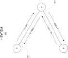
- FIGURE 1 shows an example network 100.
- the network 100 includes various entities, such as entity A, entity B, and entity C.
- connections are formed between the entities, such as connection 110 between entities A and B, and connection 120 between entities A and C.
- the entities may communicate over the connections using one or more protocols.
- a reliable transport (RT) protocol is a protocol which notifies the sender whether or not the delivery of data to an intended receiver was successful.
- a sender and a receiver are considered peers of a communication protocol, thus entities A and B may be reliable transport peers, and entities A and C may be reliable transport peers.
- a connection over which reliable transport protocol is used is an end-to-end construct that describes a bidirectional communication channel between two reliable transport peers.
- a connection may be identified by a pair of Connection IDs ("CIDs"), one in each direction of communication. CIDs may be allocated by a receiver entity during connection setup process and have no global significance outside of the parties involved.
- CIDs may be allocated by a receiver entity during connection setup process and have no global significance outside of the parties involved.
- the connection 110 between entities A and B may have a CID with value 5 for the direction from A to B, and a CID with value 10 for the direction from B to A.
- the connection 120 between entities A and C may have a CID value 5 for the direction from A to C and a CID with value 11 for the direction from C to A.
- CIDs assigned by an entity or "Source CIDs" of an entity must have different values.
- the CIDs assigned by entity A or Source CIDs of entity A have different values 10 and 11.
- "Destination CIDs" of an entity are assigned by other entities and may have the same value.
- the Destination CIDs of entity A are assigned by entities B
- Packets may be transmitted over the connections between the entities.
- a packet is a basic unit of communication across a connection.
- a packet may have a predetermined size, for example up to a maximum transfer unit ("MTU") in length.
- a packet may have a header including information about the packet and its transmission, and a payload of data.
- a reliable transport packet may include the Destination CID, such as in a header. For example, when entity B receives a packet over the connection 110 with the Destination CID of 5, entity B may identify the packet as coming from entity A, and may then notify A that the packet has been received by sending an acknowledgment over the connection 110 referencing this packet and its CID of 5. The acknowledgment itself may be sent as a packet including the Destination CID of 10.
- Entities A, B, and C may be any type of device capable of communicating over a network, such as personal computing devices, sever computing devices, mobile devices, wearable devices, virtual machines, etc.
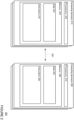
- FIGURE 2 is a block diagram of some components in an example system 200 that can communicate using a reliable transport protocol.
- the system 200 includes at least two entities having one or more connections between them. It should not be considered as limiting the scope of the disclosure or usefulness of the features described herein.
- the system 200 is shown with two entities, one or more computing devices 210 and one or more computing devices 260, with a connection 250 between them.
- computing devices 210 may be entity A and computing devices may be entity B of FIGURE 1
- connection 250 may be connection 110 of FIGURE 1 .
- the computing devices 210 and 260 may be configured with similar components as shown, or may include additional and/or different components.
- the computing devices 210 contain one or more processors 220 and memory 230.
- the one or more processors 220 can be any conventional processors, such as a commercially available CPU. Alternatively, the processors can be dedicated components such as an application specific integrated circuit ("ASIC") or other hardware-based processor. Although not necessary, the one or more of the computing devices 210 may include specialized hardware components to perform specific computing processes.
- ASIC application specific integrated circuit
- the memory 230 can be of any non-transitory type capable of storing information accessible by the processor, such as a hard-drive, memory card, ROM, RAM, DVD, CD-ROM, write-capable, and read-only memories.
- Memory 230 of the computing devices 210 can store information accessible by the one or more processors 220, including data 232 and instructions 234.
- Memory 230 can include data 232 that can be retrieved, manipulated or stored by the processors 220.
- data such as communication protocols, connection information such as CIDs, definitions of headers, etc., as described with respect to FIGURE 1 and FIGURES 3-17B may be retrieved, manipulated, or stored by the processors 220.
- Memory 230 of the computing devices 210 can also store instructions 234 that can be executed by the one or more processors 220. For instance, instructions such as communication protocols as described with reference to FIGURES 1 and 3-11 , and flow diagram of FIGURE 18 may be performed by the one or more processors 220 according to instructions 234 and data 232 in memory 230.
- Data 232 may be retrieved, stored, or modified by the one or more processors 220 in accordance with the instructions 234.
- the data can be stored in computer registers, in a relational database as a table having many different fields and records, or XML documents.
- the data can also be formatted in any computing device-readable format such as, but not limited to, binary values, ASCII or Unicode.
- the data can comprise any information sufficient to identify the relevant information, such as numbers, descriptive text, proprietary codes, pointers, references to data stored in other memories such as at other network locations, or information that is used by a function to calculate the relevant data.
- the instructions 234 can be any set of instructions to be executed directly, such as machine code, or indirectly, such as scripts, by the one or more processors.
- the terms "instructions,” “application,” “steps,” and “programs” can be used interchangeably herein.
- the instructions can be stored in object code format for direct processing by a processor, or in any other computing device language including scripts or collections of independent source code modules that are interpreted on demand or compiled in advance.
- computing devices 210 may further include other components typically present in general purpose computing devices.
- computing devices 210 may include output devices, such as displays (e.g., a monitor having a screen, a touch-screen, a projector, a television, or other device that is operable to display information), speakers, haptics, etc.
- the computing devices 210 may also include user input devices, such as a mouse, keyboard, touch-screen, microphones, sensors, etc.
- FIGURE 2 functionally illustrates the processor, memory, and other elements of computing devices 210 as being within the same block
- the processor, computer computing device, or memory can actually comprise multiple processors, computers, computing devices, or memories that may or may not be stored within the same physical housing.
- the memory can be a hard drive or other storage media located in housings different from that of the computing devices 210.
- references to a processor, computer, computing device, or memory will be understood to include references to a collection of processors, computers, computing devices, or memories that may or may not operate in parallel.
- the computing devices 210 may include server computing devices operating as a load-balanced server farm, distributed system, etc.
- some functions described below are indicated as taking place on a single computing device having a single processor, various aspects of the subject matter described herein can be implemented by a plurality of computing devices, for example, communicating information over a network.
- the computing devices 210 may be capable of directly and indirectly communicating with other entities of a network, such as computing devices 260.
- Computing devices 210 and 260 may be interconnected using various protocols and systems, such that computing devices in the network can be part of the Internet, World Wide Web, specific intranets, wide area networks, or local networks.
- Computing devices in the network can utilize standard communication protocols, such as Ethernet, WiFi and HTTP, protocols that are proprietary to one or more companies, and various combinations of the foregoing.
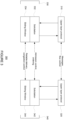
- FIGURE 3 shows an example communication protocol system 300.
- the communication protocol system 300 may be implemented on two or more entities in a network, such as two or more of entities A, B, C of network 100 of FIGURE 1 , for example by processors 220 and 270 of FIGURE 2 .
- each entity may include multiple layers of communication protocols.
- entity A may include upper layer protocol ("ULP") 310 and reliable transport ("RT") protocol 330
- entity B may include upper layer protocol 320 and reliable transport protocol layer 340.
- Peers may be formed between protocols of each layer.
- ULP 310 and ULP 320 are ULP peers
- reliable transport protocol layer 330 and reliable transport protocol layer 340 are RT peers.
- the upper layer protocols are configured to communicate with the reliable transport protocols.
- the upper layer protocols 310, 320 may be responsible for implementing the hardware/software interface, processing of messages, completion notifications, and/or end-to-end flow control.
- the upper layer protocols may be implemented on any of a number of hardware or software devices.
- the upper layer protocols may be implemented as Remote Direct Memory Access ("RDMA").
- RDMA Remote Direct Memory Access
- NVMe NonVolatile Memory Express
- the reliable transport protocols 330, 340 may be responsible for reliable delivery of packets, congestion control, admission control, and/or ordered or unordered delivery of packets.
- Each reliable transport protocols 330, 340 may logically be partitioned into two sublayers of protocols.
- reliable transport protocol layer 330 is partitioned into a solicitation sublayer 332 that is responsible for end-point admission control and optionally ordered delivery of packets, and a sliding window sublayer 334 that is responsible for end-to-end reliable delivery and congestion control.
- reliable transport protocol layer 340 is also divided into a solicitation sublayer 342 and a sliding window sublayer 344.
- FIGURE 4 shows example sliding windows 410 and 420.
- the sliding windows 410 and 420 are used by entities to keep track of a predetermined number of packets to be transmitted and acknowledged over a connection.
- entity A may use the TX sliding window 410 for keeping track of packets sent to the entity B over the connection 110, and use the RX sliding window 420 for keeping track of packets received from the entity B.
- the sliding windows 410 and 420 may be respectively implemented in the sliding window sublayer 334 that is part of the reliable transport protocol layer 330 of FIGURE 3 .
- the TX sliding window and the RX sliding window may have different sizes as shown, or may alternatively have the same size.
- each packet is assigned a Packet Sequence Number ("PSN") by the sender entity A. As shown, the bit number increases from left to right.
- the receiver entity B may acknowledge the packets it has received within the sliding window by communicating to the sender entity A the PSN it has received within the window in an acknowledgement packet.
- a Sequence Number Bitmap may be provided on both the sender entity A and the receiver entity B.
- Each bit of the Sequence Number Bitmap represents one packet within a sliding window at the entity. For example, for the TX sliding window 410, a bit is set to 1 if a sent packet has been acknowledged. Otherwise the bit is 0.
- the sender entity A may move the sliding window 410 forward to the next set of packets to be transmitted.
- the sliding window moves forward once the base sequence number packet is acknowledged, thus referring to the example in FIGURE 4 , the sliding window moves by one once the left most 0 is marked, and moves by another one once the second-left-most 0 is marked, and by three once the third 0 is marked (since the two following bits are already set).
- PSN for the sender entity may include Base Sequence Number ("BSN") and Next Sequence Number (“NSN”).
- BSN is the PSN value of the oldest packet that is yet to be acknowledged by the receiver entity B.
- Bit 0 represents a PSN value of BSN
- Bit n represents a PSN value of (BSN+n).
- the receiver entity may also keep one or more sliding windows.
- a RX sliding window may be kept by receiver entity B for the packets received, where each bit represents a packet to be received with the sliding window. The bit is set to 1 if the packet has been received by the receiver entity B. Otherwise the bit is 0.
- the receiver entity B may also use PSN to keep track of received packets.
- BSN may be the PSN value of the oldest packet that is yet to be received by the receiver entity.
- the update of the BSN may clear the bits in the Sequence Number Bitmap corresponding to packets from the previous BSN to the PSN.
- Bit 0 represents a PSN value of BSN
- Bit n represents a PSN value of (BSN+n). Because sender entity A does not acknowledge the acknowledgements sent by receiver entity B, that is, PSN is not used for the acknowledgment packets, the receiver entity B need not keep a TX sliding window for the acknowledgements it sends.
- the sender entity and receiver entity may handle the packets and the respective acknowledgements according to a set of rules. For instance, if the receiver BSN in a received packet is smaller than the sender entity's BSN, the sender entity discards the ACK information; otherwise, the sender entity updates its BSN to match the receiver entity's BSN. After adjusting its BSN, the sender entity applies an OR operation on the receiver entity's Sequence Number Bitmap in the ACK packet with its own Sequence Number Bitmap. After a packet is transmitted, it is buffered by the sender entity until it is acknowledged by the receiver entity. With respect to retransmission of failed packets, the sender entity may be configured to free up resources allocated to all ACK packets in a retransmit buffer. Further, upon per packet retransmit timer expiry, the sender entity retransmits the packet with the same PSN as the original packet, and increment a retransmission counter for that packet.
- the receiver entity may also implement a number of rules. For instance, if the PSN value of the received packet is less than the BSN of the received packet, the receiver entity discards the packet and sends an ACK packet with the current BSN. If the PSN value falls within the receiver entity's sliding window, the receiver entity updates the Sequence Number Bitmap by setting the bit at location (PSN-BSN) to 1. If the bit at location (PSN-BSN) was already 1, the packet is discarded; otherwise the packet is delivered to the ULP of the receiver entity and a cumulative ACK counter is incremented. If the PSN of the received packet is equal to BSN of the received packet, the receiver entity updates the BSN to be equal to the next highest PSN that has not been received.
- PSN-BSN Sequence Number Bitmap
- the sliding windows are configured to allow the entities to keep track of packets received and/or acknowledged out-of-order within the respective sliding window.
- packets represented by bits 3 and 4 may be sent by entity A before the packets represented by bits 0, 1, and 2, the packets represented by bits 3 and 4 may be received and/or acknowledged before the packets represented by bits 0, 1, 2 in the TX sliding window 410.
- Network congestion may be detected by monitoring packet retransmission and/or packet round-trip latencies.
- a size of the one or more sliding windows may be adjusted. For example, if congestion is high, it may take longer for all packets within the TX sliding window 410 to be received and/or acknowledged by entity B. As such, to reduce congestion, the number of outstanding packets in the network may be reduced by decreasing the size of the sliding window 410..
- retransmission timer expiry value in response to network congestion status may be adjusted. For example, retransmitting less frequently might reduce network congestion.
- the communication protocol system 300 of FIGURE 3 may support various transactions, including both pull and push transactions.
- the communication protocol system 300 of FIGURE 3 may be configured to perform the transactions using an initiator-target approach, where an "initiator" is the entity that requests a transaction, and a "target” is the entity that responds to the request.
- Such a transaction may involve multiple packets to be transmitted between the initiator and target entities, thus the initiator and the target entities may be both sender and receiver of packets in the transaction, and may keep track of packets and/or acknowledgements using TX and/or RX sliding windows as described with reference to FIGURE 4 .
- a pull transaction may be used to "pull" incoming data packets from other entities, for example for a read operation.
- the pull transaction is performed by various communication protocol layers of both the initiator entity and the target entity.
- entity A may be the initiator entity and initiator ULP 510 and initiator RT 530 may be communication protocol layers configured as upper layer protocol 310 and reliable transport protocol layer 330 of FIGURE 3
- entity B may be the target entity and target ULP 520 and target RT 540 may be communication protocol layers configured as upper layer protocol 320 and reliable transport protocol layer 340 of FIGURE 3 .
- a pull request originates from the initiator entity A, for instance from the initiator ULP 510, which is sent to the initiator RT 530.
- the initiator entity A may send the pullReq to the target entity B from which incoming data is requested, for instance over the connection 110. This may be performed by the respective RTs, thus the initiator RT 530 is shown sending the pullReq to the target RT 540.
- the target RT 540 subsequently sends the pullReq to the target ULP 520 to request permission.
- the target ULP 520 may then send an acknowledgment message ("ULP-ACK”) to the target RT 540 acknowledging the pullReq, as well as a pull response (“pullResp”) instructing the target RT 540 to pull the requested data.
- the target RT 540 may pull the requested data (“pullData”), and send the pulled data to the initiator RT 530, for instance over the connection 110.
- the initiator RT 530 may send a pullResp to the initiator ULP 510 so that the initiator ULP 510 may place or store the received data packet.
- the initiator entity A and the target entity B may communicate with each other by transmitting packets.
- the pullReq and pullData may each be a packet transmitted over the connection 110, delivered by respective RTs.
- reliable transport packets may be tracked by sliding windows.
- the pullReq packet may be part of a request TX sliding window kept by entity A (indicated by dash line), while the pullData packet may be part of a data TX sliding window kept by entity B (indicated by dash dot line).
- Each of these packets may be reliable transport packets for which an acknowledgment is required.
- entity B may send an ACK to entity A referencing the PSN of the pullReq packet, which entity A may keep track of using the request TX sliding window.
- entity A may send an ACK to entity B referencing the PSN of the pullData packet, which entity B may keep track of using the data TX sliding window.
- the pull transaction allows an initiator entity to perform end-to-end flow control.
- the initiator ULP may perform end-to-end flow control by rate limiting pullReq packets to limit the number and/or amount of outstanding pull data, which may prevent incast-induced congestion in the network. As such, incast congestion may be avoided.
- the initiator ULP may be configured to request incoming data packets based on a schedule that does not request data packets from multiple entities simultaneously. Further, the initiator RT may be configured to perform admission control to limit the amount of outstanding pulled data.
- the timing diagram 600 is shown for an example unsolicited push transaction.
- a push transaction may be used to "push" outgoing data packets to other entities, for example for a write operation.
- the push transaction is performed by various communication protocol layers of both the initiator entity and the target entity.
- entity A may be the initiator entity and initiator ULP 610 and initiator RT 630 may be communication protocol layers configured as upper layer protocol 310 and reliable transport protocol layer 330 of FIGURE 3
- entity B may be the target entity and target ULP 620 and target RT 640 may be communication protocol layers configured as upper layer protocol 320 and reliable transport protocol layer 340 of FIGURE 3 .
- a push request (“pushReq”) may originate from the initiator entity A, for instance from the initiator ULP 610, which is sent to the initiator RT 630.
- the initiator entity A may then push unsolicited data onto the target entity B, for instance over the connection 110. This may be performed by the respective RTs, thus the initiator RT 630 is shown pushing unsolicited data ("pushUnslctdData”) to the target RT 640.
- the data is unsolicited because the target entity B did not request this data.
- the target RT 640 may request for the received data to be placed or stored at the target entity B, and does so by sending a pushReq to the target ULP 620.
- the target ULP 620 may place or store the received data, and then sends an acknowledgment message ULP-ACK to the target RT 640 acknowledging that the received data has been placed or stored according to the pushReq.
- the target entity B sends an acknowledgment message ("ACK") to notify initiator entity A of the receipt and placement of the pushed data, for instance over the connection 110. This is performed by the respective RTs, thus as shown the target RT 640 sends the ACK message to the initiator RT 630.
- the initiator RT 630 may send a push complete message (“pushCmpl”) to initiator ULP 610 to notify that the data packet has been received and placed by the target entity.
- pushCmpl push complete message
- the initiator entity A and the target entity B may communicate with each other by transmitting packets.
- the pushUnslctdData and ACK may each be a packet transmitted over the connection 110.
- reliable transport packets may be tracked by sliding windows.
- the pushUnslctdData packet may be part of a data TX sliding window kept by entity A (indicated by dash dot line).
- the ACK packet sent by entity B may reference the PSN of the pushUnslctdData, which entity A may keep track of using the data TX sliding window.
- Acknowledgment messages such as the ACK packet (indicated by dot line) are not reliable transport packets, and thus may not be part of any sliding window at the sender entity B. However, because acknowledgments are cumulative - that is, an ACK received for a packet would indicate that ACKs must also have been sent for all previous packets within the sliding window - it is not necessary to make ACK messages reliable.
- the unsolicited push transaction allows an initiator entity to be notified not only of a pushed data packet being received, but also that it has been placed or stored by the target entity. In some instances, the initiator entity may wait until a pushed data packet is received and placed by the target entity before pushing another data packet.
- PushUnslctdData provides lower transaction latency, however, incast may still occur in the network if multiple initiators are sending to a same target. Such incast risk may be mitigated by limiting the size of request supported by pushUnslctdData.
- FIGURE 7 shows a timing diagram 700 for a solicited push transaction.
- the push transaction is performed by various communication protocol layers of both the initiator entity and the target entity.
- entity A may be the initiator entity and initiator ULP 710 and initiator RT 730 may be communication protocol layers configured as upper layer protocol 310 and reliable transport protocol layer 330 of FIGURE 3
- entity B may be the target entity and target ULP 720 and target RT 740 may be communication protocol layers configured as upper layer 320 and reliable transport protocol layer 340 of FIGURE 3 .
- FIGURE 7 shows that a pushReq may originate from the initiator entity A at the initiator ULP 710, which may be sent to the initiator RT 730.
- the initiator RT 730 does not send the data packet to be pushed onto the target entity B. Rather, only a request is sent to the target entity B, for instance over the connection 110, which may or may not be granted by the target entity B.
- This request and grant process or "solicitation" process may be performed by the respective RTs, which for example may be performed by their respective solicitation sublayers.
- the initiator RT 730 is shown sending a push request ("pushSlctdReq") to the target RT 740, and the target RT 740 may decide whether and/or when to grant the pushSlctdReq.
- target pushGnt is analogous as initiator pullReq.
- entity B may limit the total number of outstanding granted pushSlctdData to prevent incast to entity B that causes congestion in the network. If and when the target RT 740 grants the request, the target RT 740 may send a push grant (“pushGrnt”) back to the initiator RT 730.
- the initiator entity A may push the solicited data to the target entity B, for instance over the connection 110. This may be performed by the respective RTs, thus the initiator RT 730 is shown pushing solicited data to the target RT 740. In contrast to the unsolicited data pushed in FIGURE 6 , the data here is effectively solicited by the pushGrnt from the target RT 740.
- the target RT 740 may send a pushReq to the target ULP 720 for the received data to be placed or stored at the target entity B.
- the target ULP 720 may place or store the received data, and then sends an ULP-ACK message to the target RT 740 acknowledging that the received data has been placed according to the pushReq.
- the target entity B through target RT 740, sends an ACK message to notify initiator entity A of the receipt and placement of the pushed data, for instance over the connection 110 to the initiator RT 730.
- the initiator RT 730 may send a pushCmpl message to the initiator ULP 710 to notify that the data packet has been received and placed by the target entity B.
- the initiator entity A and the target entity B may communicate with each other by transmitting packets.
- the pushSlctdReq, pushGrnt, pushSlctdData, and ACK may each be a packet transmitted over the connection 110.
- reliable transport packets may be tracked by sliding windows.
- the pushSlctdReq may be part of a request TX sliding window kept by entity A (indicated by dash line)
- the pushGrnt packet may be part of a data TX sliding window kept by entity B (indicated by dash dot line)
- the pushSlctdData packet may be part of a data TX sliding window kept by entity A (indicated by dash dot line).
- the ACK packet sent by entity B may reference the PSN of the pushSlctdData, which entity A may keep track of using the data TX sliding window.
- entity A may send ACK for the pushGrnt packet, which entity B may keep track of using its data TX sliding window, and entity B may send ACK for the pushSlctdReq, which entity A may keep track of using its request TX sliding window.
- acknowledgment messages such as the ACK packet shown (indicated by dot line) are not reliable transport packets, and thus may not be part of any sliding window at the sender entity B.
- the solicited push transaction allows an initiator entity to solicit a grant to send data from a target entity before actually sending the data.
- the target entity may have control over the incoming data, which may be especially helpful when multiple initiator entities are attempting to push data onto the target entity, and also if the pushed data is large or if the network is congested. Since incast congestion may be caused by packets not being delivered to the receiver as fast as transmitted, and/or by multiple entities attempting to send packets simultaneously to the same entity, such a solicitation process may reduce incast congestion.
- the communication protocol system may be configured to perform one of the push transactions shown in FIGURES 6 and 7 , while in other instances, the communication protocol system may be configured to perform both of the push transactions. Where the communication protocol system is configured to perform both of the push transactions, the system may be configured to determine which push transaction to use based on one or more factors. For instance, whether a push request should be sent as a solicited or unsolicited request may be determined by the initiator RT. The initiator RT may determine whether to send a solicited push request or an unsolicited push based on a length of the push request from the initiator ULP.
- a solicited push request may be used to make sure that the large request does not cause congestion; otherwise an unsolicited push may be used.
- whether to use solicited request or unsolicited push may be based on network conditions, such as level of congestion, where a solicited request may be used when congestion meets a predetermined threshold level.
- the communication protocol system 300 of FIGURE 3 may support both ordered and unordered transactions over a connection.
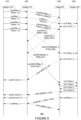
- FIGURE 8 shows an example timing diagram for ordered transactions over a connection according to aspects of the technology
- FIGURE 9 shows an example timing diagram for unordered transactions over a connection according to aspects of the technology.
- the example timing diagrams of FIGURES 8-9 may be implemented by two entities in a network, such as entities A and B over connection 110 of FIGURE 1 , for example by processors 220 and 270 of FIGURE 2 .
- various transactions may be performed by various communication protocol layers of both the initiator entity and the target entity.
- entity A may be the initiator entity and initiator ULP 810 and initiator RT 830 may be communication protocol layers configured as upper layer protocol 310 and reliable transport protocol layer 330 of FIGURE 3
- entity B may be the target entity and target ULP 820 and target RT 840 may be communication protocol layers configured as upper layer protocol 320 and reliable transport protocol layer 340 of FIGURE 3 .
- a number of requests may originate from the initiator entity A, including pull requests such as pullReq_1, and push requests such as pushReq_0, pushReq_2, and pushReq_3. As described above, these requests may be sent by the initiator ULP 810 to the initiator RT 830. Once the initiator RT 830 receives these requests, initiator RT 830 may optionally determine whether the push requests should be sent as solicited or unsolicited as described above with reference to FIGURE 7 . Thus in this example, the initiator RT 830 may determine that pushReq_0 and pushReq_2 are to be sent as solicited, while pushReq_3 is to be sent as unsolicited. The initiator RT 830 may then send these pull and push requests to the target RT 840, for example over the connection 110.
- pull requests such as pullReq_1
- push requests such as pushReq_0, pushReq_2, and pushReq_3.
- these requests may be sent by the initiator ULP 810 to the initiator
- the requests may be sent by the initiator ULP 810 in a particular order as indicated by the Request Sequence Numbers ("RSN"), which may be assigned by the initiator ULP 810.
- RSN Request Sequence Numbers
- the initiator RT 830 may also assign Solicited Sequence Numbers ("SSN") specifically to solicited push requests, which may be an incremental number as shown.
- SSN Solicited Sequence Numbers
- the requests may be assigned with a sequence of numbers in ascending order according to the order of the RSN.
- the requests may be assigned PSNs within one or more TX sliding windows maintained by initiator entity A according to the RSNs.
- pushReq_3 from the initiator ULP 810 does not require solicitation as shown in FIGURE 5 , there is no corresponding pushUnslctdReq being sent between the RTs. While RSNs and SSNs may be known to the ULPs, the PSNs may be unknown to the ULPs but only used by the RTs in packets.
- push grants may be sent by the target RT 840 to the initiator RT 830 in the order of the received requests, such as pushGnt_0 and pushGnt_2.
- the push grants may not be received in the same order by the initiator RT 830 as the order of transmission for the push requests.
- pushGrnt_2 is received by the initiator RT 830 before the pushGrnt_0.
- the initiator RT 830 may determine the correct order of the push grants based on their respective PSNs, and push the data packets based on that order. As such, although pushGrnt_2 was received by the initiator RT 830 before pushGrnt_0, the initiator RT 830 may first push the data solicited by pushGrnt_0 with pushSlctdData_0 and then push the data solicited by pushGrnt_2 with pushSlctdData_2 to target RT 840. The pushed data packets are also assigned PSNs in ascending order within one or more TX sliding windows maintained by initiator entity A according to the order of transmission.
- the pushReq_3 does not require a grant as described with reference to FIGURE 6 , thus as indicated by the curved arrow skips directly to pushUnslctdData_3, which pushes the unsolicited data.
- Target RT 840 receives the requests, and then sends corresponding requests to the target ULP 820 in the order of ULP-Req-0-1-2-3, which is in the same order as the transmission order of the requests from the initiator ULP 810 shown at the top of the timing diagram 800.
- these ULP-Reqs ask the target ULP 820 for permission to pull data, or to place the pushed data at the target entity B.
- the pull request pullReq_1 does not require a grant as described with reference to FIGURE 5 , thus as indicated by the curved arrow skips directly to the ULP-Req.
- the target ULP 820 may send acknowledgement ULP-ACKs to the target RT 840.
- the ULP-ACKs are sent in the order of ULP-ACK-0-1-2-3, which is the same as the order of transmission for the requests from the initiator ULP 810.
- ACKs acknowledging the data packets are then sent by target RT 840 to initiator RT 830 to notify the safe receipt and placement of the reliable transport data packets.
- initiator RT 830 may send a completion message pushCompl_0 to initiator ULP 810. Further, in some instances acknowledgment packets may be opportunistically piggybacked on other reliable transport packets.
- the requests pushSlctdReq_0, pullReq_1, and pushSlctdReq_2 are reliable transport packets requiring an ACK, but these acknowledgments to requests (or request ACKs) are not explicitly shown in timing diagram 800 because they may be piggybacked on reliable transport packets such as pushGrnt_0 and pushGrnt_ 2.
- pull requests may also be responded to.
- the target ULP 820 may send a pullResp_1 instructing target RT 840 to pull the requested data.
- Target RT 840 then sends the pulled data to the initiator RT 830 with pullData_1.
- the initiator RT 830 then sends a pullResp_1 to the initiator ULP 810 so that the initiator ULP 810 may place or store the received data packet at entity A.
- an acknowledgment may be sent to notify entity B of safe receipt.
- the completion messages received by the initiator ULP 810 near the bottom of timing diagram 800 are in the same order as the requests that were sent by initiator ULP 810 near the top of the timing diagram 800.
- This order is maintained on ULPs of both initiator and target entities, where the target RT presents requests to the target ULP in the same order as the initiator ULP sends requests to the initiator RT.
- This ordered system ensures that the requests are delivered once and only once over the connection. In contrast, there may not be ordering requirement between transactions going in different directions over the connection.
- FIGURE 9 shows an example timing diagram 900 for unordered transactions over a connection according to aspects of the technology.
- Timing diagram 900 may be performed by various communication protocol layers of both the initiator entity and the target entity.
- entity A may be the initiator and initiator ULP 910 and initiator RT 930 may be communication protocol layers configured as upper layer protocol 310 and reliable transport protocol layer 330 of FIGURE 3
- entity B may be the target entity and target ULP 920 and target RT 940 may be communication protocol layers configured as upper layer protocol 320 and reliable transport protocol layer 340 of FIGURE 3 .
- timing diagram 900 many of the same transactions as timing diagram 800 are shown, and are labeled as such.
- the requests are then transmitted to the target RT 940 similar to timing diagram 800.
- push requests such as pushSlctdReq_0 and pushSlctdReq_2
- push grants such as pushGrnt_0 and pushGrnt_2 are sent by target RT 940 to initiator RT 930.
- solicited data are pushed by initiator RT 930 to target RT 940 as shown with pushSlctdData_0 and pushSlctdData_2.
- unsolicited data may be pushed by initiator RT 930 to target RT 940 as shown with pushUnslctdData_3.
- pull requests such as pullReq_1
- pull requests may be sent by initiator RT 930 to target RT 940, then to target ULP 920.
- Target ULP 920 may then respond with pullResp_1, which target RT 940 responds with pullData_1 to initiator RT 930.
- Initiator RT 930 then sends pullResp_1 to initiator ULP 910, which handles the placing and/or storing of the pulled data at entity A.
- These packets may also be kept tracked of by sliding windows as described above with reference to FIGURE 8 .
- Timing diagram 900 also illustrates several aspects where the unordered system is different from the ordered system of timing diagram 800.
- the PSNs for the packets are assigned according to the order of transmission, rather than in accordance with the respective RSNs.
- the pushSlctdReq_0, pullReq_1, and pushSlctdReq_2 packets are assigned PSNs according to the order of transmission by the initiator RT 930, which happens to be the same order as the respective RSNs.
- the pushGrnt_0 and pushGrnt_2 packets also have PSNs in the order of the respective RSNs due to the transmission order.
- pushUnslctdData_3, pushSlctdData_0, and pushSlctdData_2 packets are transmitted in a different order than the order of the respective RSNs, and thus resulting in PSNs not in the same order as the respective RSNs.
- the target entity may handle the transactions out of order.
- the ULP-Reqs and the ULP-ACKs in timing diagram 900 are not sent all after the various requests and grants have been passed around the respective RTs. Rather, the ULP-Req and ULP-ACK corresponding to a particular transaction are sent as soon as the request and/or grant between the RTs are completed with respect to that particular transaction. For example, with respect to the transaction pullReq_1, ULP-Req_1 and ULP-ACK-1 are transmitted as soon as the pullReq_1 is transmitted from the initiator RT 930 to the target RT 940.
- ULP-Req_3 and ULP-ACK-3 are transmitted as soon as the pushUnslctdData_3 is transmitted from the initiator RT 930 to the target RT 940.
- the ULP-Reqs and ULP-ACKs are sent later, after the push grants and the solicited data packets are pushed from initiator RT 930 to target RT 940.
- pushSlctdData_0 is received at target RT 940 after the pushSlctdData_2, the ULP-Reqs and ULP-ACKs for these two are sent in reversed order.
- ULP-Req-1 and ULP-ACK-1 may be transmitted before ULP-Req_3, ULP-ACK_3, ULP-Req-0, ULP-Req-2, ULP-ACK-0, and ULP-ACK-2
- the target ULP 920 may nonetheless handle the pull request after the push requests.
- target RT 940 sends ACK for pushUnslctdData_3, which prompts initiator RT 930 to send pushCompl_3 to initiator ULP 910 before the ACK for pushSlctdData_0 and pushCompl_0, before pushCompl_2, and before pullResp_1.
- ACK for pushSlctdData_0, pushComp_0, and pushComp_2 may be transmitted before the pullResp_1 from initiator RT 930.
- the unordered handling of transactions by the entities as shown in FIGURE 9 allows certain transactions that are processing faster to proceed ahead of transactions that are processing slower over a given connection, which may increase the overall efficiency over the connection. For example, by allowing ULP-Reqs and ULP-ACKs to be transmitted out of order, this allows transactions with fewer steps, such as pulls and unsolicited pushes, to proceed ahead at the target ULP without waiting for other transactions with more steps at the RTs, such as solicited pushes, to complete the solicitation process. As another example, the pull request in this example may be handled later by the target ULP 920 because the push transactions have faster processing times. Additionally or alternatively, the network may deliver the packets out of order. The unordered handling of transactions may thus provide greater flexibility to speed up the overall system and increase throughput.
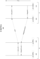
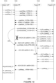
- FIGURE 10 shows an example timing diagram for a Receiver-Not-Ready (“RNR”) negative acknowledgement (“NACK”) according to aspects of the technology
- FIGURE 11 shows an example timing diagram for a completion-in-error (“compl-in-error”) NACK according to aspects of the technology.
- the example timing diagrams of FIGURES 10-11 may be implemented by two entities in a network, such as entities A and B over connection 110 of FIGURE 1 , for example by processors 220 and 270 of FIGURE 2 .
- various transactions may be performed by various communication protocol layers of both the initiator entity and the target entity.
- entity A may be the initiator entity and initiator ULP 1010 and initiator RT 1030 may be communication protocol layers configured as upper layer protocol 310 and reliable transport protocol layer 330 of FIGURE 3
- entity B may be the target entity and target ULP 1020 and target RT 1040 may be communication protocol layers configured as upper layer protocol 320 and reliable transport protocol layer 340 of FIGURE 3 .
- timing diagram 1000 shows pushReq_0, pullReq_1, and pushReq_2 originating from the initiator ULP 1010.
- the requests are then transmitted to the target RT 1040 similar to timing diagram 800.
- pushSlctdReq_0 and pushSictdReq 2 push grants pushGrnt_0 and pushGrnt_2 are sent by target RT 1040 to initiator RT 1030.
- solicited data are pushed by initiator RT 1030 to target RT 1040 as shown with pushSlctdData_0 and pushSlctdData_2.
- the pull request pullReq_1 is sent by initiator RT 1030 to target RT 1040.
- the target RT 1040 then sends pushSlctdReq_0, pullReq_1, and pushSlctdReq_2 to target ULP 1020.
- the target RT 1040 also sends acknowledgment to the initiator RT 1030 for the requests with ACK-0-1-2.
- target ULP 1020 sends negative acknowledgements ("NACK") notifying that the target ULP 1020 is not ready, and that the target RT 1040 should try again later.
- NACK negative acknowledgements
- target ULP 1020 sends pushNACK_0-retry in response to the pushSlctdReq_1, pullNACK_1-retry in response to the pullReq_1, and pushNACK_2-retry in response to the pushSlctdReq_2.
- These NACKs may include the reason for the NACK, which in this example being that the target entity is not ready, and/or may include a new timer expiry value for retransmissions.
- the target RT 1040 then sends corresponding NACKs to the initiator RT 1030, shown as NACK-200 and NACK-201 referencing the PSNs of the pushSlctdData_0 and pushSlctdData_2 packets. Note that there is no NACK to the initiator for pullReq_1 because it had already been acknowledged earlier by ACK-0-1-2. Instead, target RT 1040 keeps track of the pullNACK-1-retry, and will re-deliver to target ULP 1020 upon timer expiry. Note that the NACKs have the same eBSN because the sliding window is stuck due to the inability to acknowledge to sender.
- NACK-201 reaches the initiator RT 1030, for any of a number of reasons, the NACK-200 packet may be dropped in the network and does not reach the initiator RT 1030, and as mentioned earlier, ACK and NACK messages are not transmitted by reliable transport.
- initiator RT 1030 Because the initiator RT 1030 receives the NACK for pullSlctdReq_2, initiator RT does not attempt retransmission of pushSlctdData_2. In contrast, because the initiator RT 1030 does not receive the NACK for pushSlctdReq_0, initiator RT 1030 attempts retransmission with pushData_0-retry. For example, the initiator RT 1030 may be configured to attempt retransmission with the same PSN if it does not receive an ACK for the pushed data within a predetermined period of time.
- the target RT 1040 recognizes that pushData_0-retry is a retransmission of a data packet, for example based on the PSN of the pushData _0-retry being the same as the earlier received pushSlctdData_0.
- Target RT 1040 then sends ULP-pushReq_0 to target ULP 1020. This time, the target ULP 1020 is ready, and responds with ULP-ACK-0.
- target RT 1040 attempts again with ULP-pullReq_1 and ULP-pushSlctdReq_2 to target ULP 1020. As shown, this time the target ULP 1020 is ready and completes the requests.
- the rest of the timing diagram 1000 is similar to timing diagram 800, where the target ULP 1020 sends to target RT 1040 acknowledgments ULP-ACK-0, ULP-ACK-1, and ULP-ACK-2, then the target RT 1040 sends acknowledgments ACKs-200-201 to initiator RT 1030, and the initiator RT 1030 in turn sends completion messages pushComp_0 and pushCompl_2.
- the target ULP 1020 sends pullResp_1 to target RT 1040, which then sends pullResp_1 to initiator RT 1030, which then sends completion message pullCompl_1 to initiator ULP 1010.
- FIGURE 10 illustrates that, by allowing the initiator RT to retransmit requests and/or data when an ACK or NACK is not received within a predetermined period of time, RT works robustly and reliably over potentially lossy network. Further, by not allowing the initiator RT to retransmit when a NACK is received, congestion over the network may be reduced. Still further, by allowing the target RT to retransmit requests and/or data to target ULP, the requests may be handled at a later time when the target ULP is ready, rather than resulting in a deadlock or time-out.
- various transactions may be performed by various communication protocol layers of both the initiator entity and the target entity.
- entity A may be the initiator and initiator ULP 1110 and initiator RT 1130 may be communication protocol layers configured as upper layer protocol 310 and reliable transport protocol layer 330 of FIGURE 3
- entity B may be the target entity and target ULP 1120 and target RT 1140 may be communication protocol layers configured as upper layer protocol 320 and reliable transport protocol layer 340 of FIGURE 3 .
- timing diagram 1100 many of the same transactions as timing diagram 800 are shown, and are labeled as such.
- timing diagram 1100 shows pushReq_0, pullReq_1, and pushReq_2 originating from initiator ULP 1110.
- the requests are then transmitted to the target RT 1140 similar to timing diagram 800.
- pushSlctdReq_0 and pushSictdReq 2 push grants pushGrnt_0 and pushGrnt_2 are sent by target RT 1140 to initiator RT 1130.
- solicited data are pushed by initiator RT 1130 to target RT 1140 as shown with pushSlctdData_0 and pushSlctdData_2.
- the pull request pullReq_1 is sent by initiator RT 1130 to target RT 1140.
- the target RT 1140 then sends pushSlctdReq_0, pullReq_1, and pushSlctdReq_2 to target ULP 1120.
- target ULP 1120 completes the pushSlctdData_0 in error. Accordingly, target ULP 1120 sends a pushNACK_0-compl-in-err notifying the target RT 1140 of the error.
- the NACK may include reason for the NACK, which in this example is that the placement or storing of the pushed data was completed in error.
- the NACK may optionally include information on the error, such as the reason.
- the target RT 1140 then sends a corresponding NACK to the initiator RT 1130, shown as NACK-200 referencing the PSN of the pushSlctdData_0.
- NACK-200 does not reach the initiator RT 1130.
- the target ULP 1120 completes the other requests successfully, and sends ULP-ACK_1, ULP-ACK_2, and pullResp_1 to target RT 1140, which prompts target RT 1140 to send ACK-201 and pullResp_1 to initiator RT 1130.
- initiator RT 1130 does not receive the NACK for pushSlctdReq_0, initiator RT 1130 attempts retransmission with pushData_0-retry.
- the initiator RT 1130 may be configured to attempt retransmission with the same PSN if it does not receive an ACK for the pushed data within a predetermined period of time.
- the target RT 1140 recognizes that pushData_0-retry is a retransmission of a data packet, for example based on the PSN of the pushData_0-retry being the same as the earlier received pushSlctdData_0. As such, the target RT 1140 resends the NACK-200 without having to send another push request to the target ULP 1120.
- a resynchronization may be performed.
- the resynchronization may be initiated by the initiator RT 1130 with "resync-pkt.”
- the resynchronization prompts the target RT 1140 to send an acknowledgement that allows the one or more current sliding windows to move to a next set of packets to be transmitted and/or received. As shown, this is done by the target RT 1140 sending an acknowledgement ACK-200, rather than a negative acknowledgment, to the initiator RT 1130 in response to the resync-pkt.
- the initiator RT 1130 then sends completion messages pushCompl_0-in-err, pullCompl_1, and pushCompl_2 to the initiator ULP 1110, which notifies of both successful completions and the completion in error.
- FIGURE 11 illustrates that the resynchronization process prevents the current sliding windows from being stuck. Further, in contrast to many protocols where a complete in error may result in time-out or tearing down of a connection, the resynchronization process allows a more resilient connection to be maintained between entities.
- FIGURE 11 also illustrates an example timescale for the process. As shown, one roundtrip time (“RTT") may have passed between the time that the pushSlctdReq_0 is sent by the initiator RT 1130 and the pushGrnt_0 being received by the initiator RT 1130. Then, between the pushGrnt_0 being received by the initiator RT 1130 and the NACK-200 being receive by the initiator RT 1130, several RTTs may have passed. Another RTT may have passed between the time that the resync-pkt is sent by the initiator RT 1130 and the time that pushCompl_0-in-err is sent by the initiator RT 1130.
- RTT roundtrip time
- FIGURES 10 and 11 are provided for an ordered system, in other examples the timing diagrams may be performed by an unordered system. In such instances, similar process may be performed without the ordering requirements.
- the communication protocol system 300 may additionally be provided with or associated with one or more congestion control engines.
- congestion control engines may be configured with any of a number of algorithms, such as SWIFT, BBR, GCN, etc.
- the congestion control algorithm may be implemented in software, firmware, or hardware.
- the congestion control algorithm may be implemented in host software, in a network interface's ("NIC") firmware, or in a hardware rate update engine.
- the communication protocol system 300 may provide a rate update event and result queue interface to the rate update engine.
- Congestion signals may be provided in the event queue, which may include measurements of RTT, explicit congestion notification ("ECN”) marking, retransmission status, etc.
- ECN explicit congestion notification
- Rate update engine may report the results back to the communication protocol system 300, based on which congestion control may be implemented.
- the report may include congestion window ("Cwnd”), which is the total number of outstanding TX packets. When this value is between 0 and 1, the communication protocol system 300, for example the sender RT, may apply additional inter-packet gap to limit the number of packet transmission to be less than 1 per RTT.
- the report may include retransmission timeout ("RTO”), which is the time the sender entity waits before retransmitting a pending TX packet if no ACK is received.
- RTO retransmission timeout
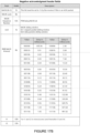
- FIGURES 12A-17B show example headers and definitions according to aspects of the technology. These example headers are provided merely as illustrations, and in practice may take any other format, and may include alternative or additional information.
- the example headers may be used by various communication protocol layers of entities when implementing the sliding window of FIGURE 4 , and/or the timing diagrams of FIGURES 5-11 .
- FIGURES 12A-B describe an example base header to be included by all packets within a communication protocol system.
- FIGURES 13A-F describe example headers for request and grant packets in the communication protocol system.
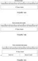
- FIGURES 14A-C describe example headers for data packets in the communication protocol system.
- FIGURES 15A-B describe an example resynchronization packet in the communication protocol system.
- FIGURES 16A-B describe an example acknowledgement packet in the communication protocol system.
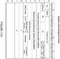
- FIGURES 17A-B describe an example negative acknowledgement packet in the communication protocol system.
- the example base header shown includes various fields of information.
- the "Proto Type” field may specify the various protocols to be used for the packet, such as RT protocol, ULP protocol, storage protocol, etc.
- the "ULP protocol” may specify the different ULP types supported, for example, RDMA, NVMe, etc.
- the "Packet Type” field may specify a type of the packet, such as the various requests, grants, data, ACK, NACK, resync, etc. described above.
- the base header may include various sequence numbers for the packet, such as PSN and RSN described above, as well as expected base packet sequence number in the RX direction for the data sliding window ("eDBSN") and expected base packet sequence number in the RX direction for the request sliding window ("eRBSN"). Further, the base header may include the destination CID identifying the communication direction over a connection towards the intended receiver entity.
- FIGURES 13A-13F show example request and grant headers each including the base header of FIGURE 12A , and optionally some additional information.
- FIGURES 13A and 13D describe an example pull request header, which may include additional information such as a "request length" field specifying a size of the returning pull response packet, and/or reserved customizable fields.
- FIGURES 13B and 13E describe an example push request header, which may similarly include a request length field specifying size of the outgoing push data packet.
- the push request header may further include an SSN field specifying the order of the solicitation.
- FIGURES 13C and 13F describe an example push grant header for a solicited push request, which may include a request length field, an SSN field, SPH Reassembly Context ID and SPH Replay Count fields.
- FIGURES 14A-14C show example data headers each including the base header of FIGURE 12A , and optionally some additional information.
- the example pull data header in FIGURE 14A and the example push data header in FIGURE 14B each includes the base header of FIGURE 12A , with no additional information.
- the example push unsolicited data header of FIGURE 14C includes the base header of FIGURE 12A , but also additionally includes a request length field specifying a size of the unsolicited data packet being pushed.
- FIGURES 15A and 15B describe an example resynchronization header, which includes the base header of FIGURE 12A , and optionally additional information.
- the resynchronization header may include a "Resync Code” field specifying the target ULP to which the resynchronization packet is sent, memory deallocation, and other information.
- the resynchronization header may further include a "resynch type" field that specifies the type of the original packet being resynched. SSN may be provided if the resynch type is solicited push request or push grant.
- FIGURES 16A and 16B describe an example acknowledgment or ACK header.
- the example ACK header includes some same fields as the base header of FIGURE 12A , but instead of PSN and RSN fields, the ACK header includes "Receiver Data Window Sequence Bitmap” and "Receiver Request Window Sequence Bitmap” fields.
- a value of "1" in such a bitmap indicates a packet has been acknowledged
- a "0" indicates that the packet has not been acknowledged.
- the value "N0" in the example ACK header for the field NACK indicates that the packet is an ACK instead of a NACK.
- the ACK header may include a congestion control metadata field, which RT may carry between two entities to facilitate congestion control algorithms, and one or more timestamps for measuring latency in the network.
- FIGURES 17A and 17B describe an example negative acknowledgment or NACK header.
- the example NACK header includes some same fields as the base header of FIGURE 12A , but instead of PSN and RSN fields, the NACK header includes a "NACK Sequence Number" field specifying the PSN of the packet being negatively acknowledged.
- the example NACK header also includes some same fields as the ACK header of FIGURE 16 . For example, the value "N1" in the example NACK header for the field NACK indicates that the packet is a NACK.
- the example NACK header also includes fields not found in the base header or the ACK header.
- the NACK header may include a "NACK code” field, which for example may provide reasons for the NACK, such as excessive network jitters, receiver resource resulted drop, receiver not ready, etc.
- the NACK header may also include a "wnd” field indicating the sliding window(s) the NACK is directed to.
- the NACK header may further include an "RNR-NACK timeout” field, which specifies the timer expiry value for retransmission.
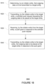
- FIGURE 18 shows an example flow diagram illustrating an example method in accordance with aspects of the disclosure. The method may be performed using the systems described above, modifications thereof, or any of a variety of systems having different configurations. It should be understood that the operations involved in the following methods need not be performed in the precise order described. Rather, various operations may be handled in a different order or simultaneously, and operations may be added or omitted. Although FIGURE 18 illustrates one example method, variations of the methods may be performed, for instance as described above with reference to FIGURES 1-11 .
- FIGURE 18 an example flow diagram 1800 is shown illustrating a solicited push transaction.
- the flow diagram 1800 may be performed by one or more entities in a network, such as by any of the entities A, B, C of FIGURE 1 , for example by processors 220 of FIGURE 2 .
- the processors 220 may include processors on one entity, such as entity 110, or processors on multiple entities, such as on two or more of entities A, B, C, etc.
- processors 220 may receive data, and perform reliable transport as described above with reference to FIGURES 1-11 , which may include use of headers as shown in FIGURES 12A-17B .
- an initiator entity determines by an initiator entity that outgoing data is to be transmitted to a target entity.
- the initiator entity transmits to the target entity, a solicited push request requesting the outgoing data to be placed at the target entity.
- the initiator entity receives from the target entity, a push grant in response to the solicited push request.
- the initiator entity transmits to the target entity, the outgoing data to be placed at the target entity in response to the push grant.
- an initiator entity may determine that outgoing data is to be transmitted to a target entity.
- the initiator entity may transmit, to the target entity, a solicited push request requesting the outgoing data to be placed at the target entity.
- the initiator entity may receive a push grant from the target entity.
- the initiator entity may transmit to the target entity the outgoing data to be placed at the target entity.
- the technology generally relates to communication protocols for reliable transport of packets over a connection.
- the technology provides solicitation based push transactions, which provides a receiver entity control over incoming data and thus reduce incast congestion and tail latency.
- the technology further supports unordered transactions over a connection using sliding windows and bitmaps, which may increase overall efficiency in handling of packets over the connection.
- the technology further provides handling of failed transmissions that reduces retransmission attempts and uses resynchronization to prevent tearing down of connections, thus resulting in more resilient connections.
Landscapes
- Engineering & Computer Science (AREA)
- Computer Networks & Wireless Communication (AREA)
- Signal Processing (AREA)
- Computer Security & Cryptography (AREA)
- Communication Control (AREA)
- Data Exchanges In Wide-Area Networks (AREA)
- Mobile Radio Communication Systems (AREA)
Claims (4)
- Procédé, comprenant :la transmission, à partir d'un protocole de couche supérieure, ULP, d'une entité initiatrice (910) vers un protocole de transport fiable, RT, de l'entité initiatrice (930), d'une pluralité de requêtes push pour pousser des paquets de données sortants vers une entité cible (920, 940) sur une connexion (110), et d'une ou de plusieurs requêtes pull pour tirer des paquets de données entrants à partir de l'entité cible (920, 940) sur la connexion (110), la pluralité de requêtes push comportant des requêtes push sollicitées et non sollicitées ;la détermination (1810), par le RT de l'entité initiatrice (930), qu'au moins une de la pluralité de requêtes push doit être transmise à l'entité cible (920, 940) en tant que requête push sollicitée,la transmission (1820), par le RT de l'entité initiatrice (930) à l'entité cible (920, 940), de l'au moins une de la pluralité de requêtes push et des une ou plusieurs requêtes pull, et l'attribution, par l'entité initiatrice (910, 930) à chacune de la pluralité de requêtes push et des une ou plusieurs requêtes pull, d'un numéro de séquence de paquets, PSN, selon un ordre de transmission, l'au moins une de la pluralité de requêtes push demandant que des premiers paquets de données sortants soient stockés au niveau de l'entité cible (920, 940) via une couche de protocole de transport fiable, RT (330, 340), la couche de protocole RT (330, 340) comportant une sous-couche de sollicitation (332, 342) et une sous-couche de fenêtre glissante (342, 344), dans lequel la sous-couche de fenêtre glissante (342, 344) met en œuvre une ou plusieurs fenêtres glissantes (410, 420) pour garder une trace d'un nombre prédéterminé de paquets à transmettre et à reconnaître sur la connexion (110) ; la réception (1830), par le RT de l'entité initiatrice (930) à partir de l'entité cible (920, 940), d'un ou de plusieurs paquets d'octroi push en réponse à l'au moins une de la pluralité de requêtes push ;la transmission (1840), par le RT de l'entité initiatrice (930) à l'entité cible (920, 940), des premiers paquets de données sortants à stocker au niveau de l'entité cible (920, 940) en réponse aux un ou plusieurs paquets d'octroi push ; etl'envoi, par l'entité cible (920, 940) au RT de l'entité initiatrice (930), d'au moins deux paquets d'accusé de réception, ACK, indiquant que des paquets de données sortants ont été reçus et stockés par l'entité cible (920, 940), dans lequel les au moins deux paquets ACK référencent un ou plusieurs PSN attribués par l'entité initiatrice (910, 930) à chacune de la pluralité de requêtes push, dans lequel l'entité initiatrice (910, 930) garde une trace des PSN attribués à l'aide des une ou plusieurs fenêtres glissantes (410, 420), et dans lequel les au moins deux paquets ACK sont reçus par le RT de l'entité initiatrice (930) et un paquet ACK est envoyé à l'entité cible pour accuser réception des données tirées de l'entité cible, dans un second ordre différent de l'ordre de la pluralité de requêtes push transmises et des une ou plusieurs requêtes pull.
- Procédé selon la revendication 1, comprenant également :la détermination, par le RT de l'entité initiatrice (930), qu'au moins une de la pluralité de requêtes push doit être transmise à l'entité cible (920, 940) en tant que requête push sollicitée sur la base d'une taille des premiers paquets de données sortants ; eten réponse aux premiers paquets de données sortants atteignant un seuil prédéterminé, la transmission d'au moins une de la pluralité de requêtes push en tant que requêtes push sollicitées.
- Procédé selon la revendication 2, dans lequel la pluralité de requêtes push proviennent de l'ULP de l'entité initiatrice (910), sur la base duquel le RT de l'entité initiatrice (930) transmet l'au moins une requête push sollicitée en tant que paquets sur la connexion entre l'entité initiatrice (910, 930) et l'entité cible (920, 940).
- Procédé selon l'une des revendications 1 à 3, comprenant également :la détermination, par l'entité initiatrice (910, 930), qu'un ou plusieurs paquets de données entrants sont nécessaires à partir de l'entité cible (920, 940) ;la transmission, par l'entité initiatrice (910, 930) à l'entité cible (920, 940), d'une ou de plusieurs requêtes pull demandant que les un ou plusieurs paquets de données entrants soient transmis à l'entité initiatrice (910, 930) ;la réception, par l'entité initiatrice (910, 930) à partir de l'entité cible (920, 940), des un ou plusieurs paquets de données entrants en réponse aux un ou plusieurs paquets de requêtes pull ; etde préférence comprenant également :
la planification, par l'entité initiatrice (910, 930) sur la base d'un ou de plusieurs paramètres de congestion, des une ou plusieurs requêtes pull pour les un ou plusieurs paquets de données entrants.
Priority Applications (1)
| Application Number | Priority Date | Filing Date | Title |
|---|---|---|---|
| EP25150213.4A EP4510540A3 (fr) | 2019-12-12 | 2020-11-13 | Protocole de transport fiable et architecture matérielle pour mise en réseau de centre de données |
Applications Claiming Priority (2)
| Application Number | Priority Date | Filing Date | Title |
|---|---|---|---|
| US201962947036P | 2019-12-12 | 2019-12-12 | |
| US16/819,327 US11463547B2 (en) | 2019-12-12 | 2020-03-16 | Reliable transport protocol and hardware architecture for datacenter networking |
Related Child Applications (2)
| Application Number | Title | Priority Date | Filing Date |
|---|---|---|---|
| EP25150213.4A Division-Into EP4510540A3 (fr) | 2019-12-12 | 2020-11-13 | Protocole de transport fiable et architecture matérielle pour mise en réseau de centre de données |
| EP25150213.4A Division EP4510540A3 (fr) | 2019-12-12 | 2020-11-13 | Protocole de transport fiable et architecture matérielle pour mise en réseau de centre de données |
Publications (3)
| Publication Number | Publication Date |
|---|---|
| EP3836508A2 EP3836508A2 (fr) | 2021-06-16 |
| EP3836508A3 EP3836508A3 (fr) | 2021-08-04 |
| EP3836508B1 true EP3836508B1 (fr) | 2025-02-12 |
Family
ID=73448810
Family Applications (2)
| Application Number | Title | Priority Date | Filing Date |
|---|---|---|---|
| EP20207349.0A Active EP3836508B1 (fr) | 2019-12-12 | 2020-11-13 | Protocole de transport fiable et architecture matérielle pour réseautage de centre de données |
| EP25150213.4A Pending EP4510540A3 (fr) | 2019-12-12 | 2020-11-13 | Protocole de transport fiable et architecture matérielle pour mise en réseau de centre de données |
Family Applications After (1)
| Application Number | Title | Priority Date | Filing Date |
|---|---|---|---|
| EP25150213.4A Pending EP4510540A3 (fr) | 2019-12-12 | 2020-11-13 | Protocole de transport fiable et architecture matérielle pour mise en réseau de centre de données |
Country Status (3)
| Country | Link |
|---|---|
| US (3) | US11463547B2 (fr) |
| EP (2) | EP3836508B1 (fr) |
| CN (3) | CN119094513A (fr) |
Families Citing this family (6)
| Publication number | Priority date | Publication date | Assignee | Title |
|---|---|---|---|---|
| US12443657B2 (en) * | 2021-05-25 | 2025-10-14 | Google Llc | High bandwidth content addressable memory (CAM) based hardware architecture for datacenter networking |
| US12019542B2 (en) | 2022-08-08 | 2024-06-25 | Google Llc | High performance cache eviction |
| US11979476B2 (en) * | 2022-10-07 | 2024-05-07 | Google Llc | High performance connection scheduler |
| US12199746B2 (en) | 2022-10-19 | 2025-01-14 | Google Llc | Mechanism for precise time synchronization in a datacenter network |
| US12164439B1 (en) | 2023-06-02 | 2024-12-10 | Google Llc | Hardware architecture of packet cache eviction engine |
| US12463938B2 (en) * | 2023-09-30 | 2025-11-04 | Juniper Networks, Inc. | Devices, systems, and methods for installing binding information after failures caused by transient errors |
Citations (1)
| Publication number | Priority date | Publication date | Assignee | Title |
|---|---|---|---|---|
| WO2000072575A2 (fr) * | 1999-05-24 | 2000-11-30 | Hewlett-Packard Company | Service de transport fiable de datagrammes |
Family Cites Families (49)
| Publication number | Priority date | Publication date | Assignee | Title |
|---|---|---|---|---|
| US6247059B1 (en) * | 1997-09-30 | 2001-06-12 | Compaq Computer Company | Transaction state broadcast method using a two-stage multicast in a multiple processor cluster |
| US6330226B1 (en) * | 1998-01-27 | 2001-12-11 | Nortel Networks Limited | TCP admission control |
| US6330451B1 (en) * | 1998-10-13 | 2001-12-11 | Nortel Networks Limited | Selectively delaying data communications in a wireless communication system to provide voice communications capacity |
| US6424625B1 (en) * | 1998-10-28 | 2002-07-23 | Telefonaktiebolaget Lm Ericsson (Publ) | Method and apparatus for discarding packets in a data network having automatic repeat request |
| US7630986B1 (en) * | 1999-10-27 | 2009-12-08 | Pinpoint, Incorporated | Secure data interchange |
| AU2001271609A1 (en) | 2000-06-30 | 2002-01-14 | Kanad Ghose | System and method for fast, reliable byte stream transport |
| US7039032B1 (en) * | 2000-07-14 | 2006-05-02 | At&T Corp. | Multipoll for QoS-Driven wireless LANs |
| JP4433202B2 (ja) * | 2003-07-11 | 2010-03-17 | 日本電気株式会社 | トランスポート層中継方法及びトランスポート層中継装置並びにプログラム |
| US7443791B2 (en) | 2003-10-10 | 2008-10-28 | Microsoft Corporation | Priority mechanism for distributed sending of media data |
| US7636313B2 (en) * | 2003-12-23 | 2009-12-22 | Microsoft Corporation | Use of internal buffer to reduce acknowledgement related delays in acknowledgement-based reliable communication protocols |
| US7826470B1 (en) * | 2004-10-19 | 2010-11-02 | Broadcom Corp. | Network interface device with flow-oriented bus interface |
| AU2011203511B2 (en) * | 2004-12-24 | 2013-10-31 | International Business Machines Corporation | Bulk data transfer |
| US7756036B2 (en) * | 2005-12-22 | 2010-07-13 | Intuitive Surgical Operations, Inc. | Synchronous data communication |
| US7773509B2 (en) * | 2006-03-07 | 2010-08-10 | Samsung Electronics Co., Ltd. | Method and system for traffic control for providing quality of service in a network |
| JP4729000B2 (ja) * | 2006-04-27 | 2011-07-20 | イノヴァティヴ ソニック リミテッド | 無線通信システムにおいて復号パラメータを同期させる方法及び装置 |
| JP5021728B2 (ja) * | 2006-05-29 | 2012-09-12 | サムスン エレクトロニクス カンパニー リミテッド | 中継方式を使用する無線通信システムにおける再送信装置及び方法 |
| US8477614B2 (en) * | 2006-06-30 | 2013-07-02 | Centurylink Intellectual Property Llc | System and method for routing calls if potential call paths are impaired or congested |
| US8571061B2 (en) * | 2006-07-07 | 2013-10-29 | Avaya Communications Israel Ltd. | Inter-network translation |
| US7782771B2 (en) * | 2007-01-05 | 2010-08-24 | Microsoft Corporation | Adjusting to network latency changes |
| KR20090122986A (ko) * | 2007-04-06 | 2009-12-01 | 가부시키가이샤 엔티티 도코모 | 패킷통신방법 및 수신측 장치 |
| US9965731B2 (en) * | 2007-06-22 | 2018-05-08 | International Business Machines Corporation | Highly ordered transaction processing |
| US8032892B2 (en) * | 2007-06-26 | 2011-10-04 | International Business Machines Corporation | Message passing with a limited number of DMA byte counters |
| US8732236B2 (en) * | 2008-12-05 | 2014-05-20 | Social Communications Company | Managing network communications between network nodes and stream transport protocol |
| US7996548B2 (en) * | 2008-12-30 | 2011-08-09 | Intel Corporation | Message communication techniques |
| US8306062B1 (en) * | 2008-12-31 | 2012-11-06 | Marvell Israel (M.I.S.L) Ltd. | Method and apparatus of adaptive large receive offload |
| US8213315B2 (en) * | 2009-11-19 | 2012-07-03 | Mellanox Technologies Ltd. | Dynamically-connected transport service |
| US20110134930A1 (en) * | 2009-12-09 | 2011-06-09 | Mclaren Moray | Packet-based networking system |
| US9813529B2 (en) * | 2011-04-28 | 2017-11-07 | Microsoft Technology Licensing, Llc | Effective circuits in packet-switched networks |
| US20120287814A1 (en) * | 2011-05-12 | 2012-11-15 | Fluke Corporation | Method and apparatus to determine the amount of data outstanding throughout the life of a tcp flow (socket connection) |
| US20130163417A1 (en) * | 2011-12-27 | 2013-06-27 | Mitel Networks Corporation | Application level admission overload control |
| US9013995B2 (en) * | 2012-05-04 | 2015-04-21 | Telefonaktiebolaget L M Ericsson (Publ) | Congestion control in packet data networking |
| US9319474B2 (en) * | 2012-12-21 | 2016-04-19 | Qualcomm Incorporated | Method and apparatus for content delivery over a broadcast network |
| JP6142920B2 (ja) * | 2013-05-10 | 2017-06-07 | 富士通株式会社 | 無線通信システム、移動局、基地局及び無線通信方法 |
| US10432529B2 (en) | 2013-09-19 | 2019-10-01 | Connectivity Systems Incorporated | Enhanced large data transmissions and catastrophic congestion avoidance over IPv6 TCP/IP networks |
| US10149328B2 (en) * | 2014-01-28 | 2018-12-04 | Telefonaktiebolaget Lm Ericsson (Publ) | Radio network controller and a method therein for managing a random access channel |
| US9410712B2 (en) * | 2014-10-08 | 2016-08-09 | Google Inc. | Data management profile for a fabric network |
| US9979591B2 (en) * | 2015-08-28 | 2018-05-22 | Samsung Electronics Co., Ltd. | Event notifications for applications |
| US9986054B2 (en) * | 2015-11-19 | 2018-05-29 | Movren Management Limited | Enhanced push notification for alerts |
| US10148543B2 (en) | 2015-12-23 | 2018-12-04 | EMC IP Holding Company LLC | Connection-oriented communication devices with round trip time estimation |
| US10205801B2 (en) | 2016-01-12 | 2019-02-12 | International Business Machines Corporation | Data transfer policies between source and target servers in a wide area network |
| WO2017147307A1 (fr) * | 2016-02-23 | 2017-08-31 | Level 3 Communications, Llc | Contrôle de flux de réseau |
| US10430374B2 (en) * | 2016-06-29 | 2019-10-01 | Mellanox Technologies, Ltd. | Selective acknowledgement of RDMA packets |
| US11172016B2 (en) * | 2017-03-30 | 2021-11-09 | Intel Corporation | Device, method and system to enforce concurrency limits of a target node within a network fabric |
| CN108111434B (zh) | 2017-12-14 | 2021-03-16 | 四川大学 | 一种基于可靠udp和喷泉码的航空自组网可靠传输方法 |
| US11016911B2 (en) * | 2018-08-24 | 2021-05-25 | Samsung Electronics Co., Ltd. | Non-volatile memory express over fabric messages between a host and a target using a burst mode |
| US11102129B2 (en) * | 2018-09-09 | 2021-08-24 | Mellanox Technologies, Ltd. | Adjusting rate of outgoing data requests for avoiding incast congestion |
| US20200145881A1 (en) * | 2018-11-06 | 2020-05-07 | Qualcomm Incorporated | System and method for flow control and buffer status report |
| CN109660467B (zh) * | 2019-02-26 | 2022-12-23 | 北京百度网讯科技有限公司 | 用于控制流量的方法和装置 |
| US11778533B2 (en) * | 2019-08-02 | 2023-10-03 | Comcast Cable Communications, Llc | Path optimization in a mesh network |
-
2020
- 2020-03-16 US US16/819,327 patent/US11463547B2/en active Active
- 2020-11-13 CN CN202411308868.8A patent/CN119094513A/zh active Pending
- 2020-11-13 CN CN202011269309.2A patent/CN112383622B/zh active Active
- 2020-11-13 CN CN202411306447.1A patent/CN119011563A/zh active Pending
- 2020-11-13 EP EP20207349.0A patent/EP3836508B1/fr active Active
- 2020-11-13 EP EP25150213.4A patent/EP4510540A3/fr active Pending
-
2022
- 2022-07-05 US US17/857,620 patent/US11824954B2/en active Active
-
2023
- 2023-09-13 US US18/367,679 patent/US12132800B2/en active Active
Patent Citations (1)
| Publication number | Priority date | Publication date | Assignee | Title |
|---|---|---|---|---|
| WO2000072575A2 (fr) * | 1999-05-24 | 2000-11-30 | Hewlett-Packard Company | Service de transport fiable de datagrammes |
Also Published As
| Publication number | Publication date |
|---|---|
| US12132800B2 (en) | 2024-10-29 |
| US11463547B2 (en) | 2022-10-04 |
| US20220337675A1 (en) | 2022-10-20 |
| CN112383622A (zh) | 2021-02-19 |
| US20210185139A1 (en) | 2021-06-17 |
| EP3836508A2 (fr) | 2021-06-16 |
| CN119094513A (zh) | 2024-12-06 |
| US20230421657A1 (en) | 2023-12-28 |
| EP4510540A3 (fr) | 2025-04-30 |
| CN112383622B (zh) | 2024-10-01 |
| CN119011563A (zh) | 2024-11-22 |
| EP4510540A2 (fr) | 2025-02-19 |
| EP3836508A3 (fr) | 2021-08-04 |
| US11824954B2 (en) | 2023-11-21 |
Similar Documents
| Publication | Publication Date | Title |
|---|---|---|
| EP3836508B1 (fr) | Protocole de transport fiable et architecture matérielle pour réseautage de centre de données | |
| US10430374B2 (en) | Selective acknowledgement of RDMA packets | |
| US7035291B2 (en) | TCP transmission acceleration | |
| US20230362098A1 (en) | Rate Update Engine For Reliable Transport Protocol | |
| US20030137939A1 (en) | Method and apparatus for controlling the flow of data between servers using optimistic transmitter | |
| US20050013246A1 (en) | Communication device, transmission control method, and program product | |
| US11283719B2 (en) | Content addressable memory (CAM) based hardware architecture for datacenter networking | |
| US20100217889A1 (en) | Accelerated block option for trivial file transfer protocol (tftp) | |
| CN108234089B (zh) | 用于低时延通信的方法和系统 | |
| EP4407911A2 (fr) | Module de coalescence d'accusé de réception utilisé dans une architecture matérielle basée sur une mémoire adressable par le contenu (cam) pour la mise en réseau de centres de données | |
| US11463339B2 (en) | Device and method for delivering acknowledgment in network transport protocols | |
| US12192004B2 (en) | Device and method for selective retransmission of lost packets | |
| US8769137B2 (en) | Systems and methods for negotiated accelerated block option for trivial file transfer protocol (TFTP) | |
| EP4145803B1 (fr) | Architecture matérielle d'antémémoire de connexion de transport fiable soutenue par une mémoire hors puce | |
| US12443657B2 (en) | High bandwidth content addressable memory (CAM) based hardware architecture for datacenter networking | |
| WO2021249651A1 (fr) | Dispositif et procédé permettant de fournir un accusé de réception dans des protocoles de transport de réseau | |
| HK40089884A (en) | Off-chip memory backed reliable transport connection cache hardware architecture | |
| WO2021223853A1 (fr) | Dispositif et procédé pour délivrer un accusé de réception dans des protocoles de transport de réseau |
Legal Events
| Date | Code | Title | Description |
|---|---|---|---|
| PUAI | Public reference made under article 153(3) epc to a published international application that has entered the european phase |
Free format text: ORIGINAL CODE: 0009012 |
|
| STAA | Information on the status of an ep patent application or granted ep patent |
Free format text: STATUS: THE APPLICATION HAS BEEN PUBLISHED |
|
| AK | Designated contracting states |
Kind code of ref document: A2 Designated state(s): AL AT BE BG CH CY CZ DE DK EE ES FI FR GB GR HR HU IE IS IT LI LT LU LV MC MK MT NL NO PL PT RO RS SE SI SK SM TR |
|
| PUAL | Search report despatched |
Free format text: ORIGINAL CODE: 0009013 |
|
| AK | Designated contracting states |
Kind code of ref document: A3 Designated state(s): AL AT BE BG CH CY CZ DE DK EE ES FI FR GB GR HR HU IE IS IT LI LT LU LV MC MK MT NL NO PL PT RO RS SE SI SK SM TR |
|
| RIC1 | Information provided on ipc code assigned before grant |
Ipc: H04L 29/06 20060101AFI20210629BHEP Ipc: H04L 29/08 20060101ALI20210629BHEP |
|
| STAA | Information on the status of an ep patent application or granted ep patent |
Free format text: STATUS: REQUEST FOR EXAMINATION WAS MADE |
|
| 17P | Request for examination filed |
Effective date: 20220203 |
|
| RBV | Designated contracting states (corrected) |
Designated state(s): AL AT BE BG CH CY CZ DE DK EE ES FI FR GB GR HR HU IE IS IT LI LT LU LV MC MK MT NL NO PL PT RO RS SE SI SK SM TR |
|
| STAA | Information on the status of an ep patent application or granted ep patent |
Free format text: STATUS: EXAMINATION IS IN PROGRESS |
|
| 17Q | First examination report despatched |
Effective date: 20230112 |
|
| REG | Reference to a national code |
Ref country code: DE Ref legal event code: R079 Free format text: PREVIOUS MAIN CLASS: H04L0029060000 Ipc: H04L0069160000 Ref country code: DE Ref legal event code: R079 Ref document number: 602020045847 Country of ref document: DE Free format text: PREVIOUS MAIN CLASS: H04L0029060000 Ipc: H04L0069160000 |
|
| RIC1 | Information provided on ipc code assigned before grant |
Ipc: H04L 67/55 20220101ALI20240417BHEP Ipc: H04L 67/025 20220101ALI20240417BHEP Ipc: H04L 67/14 20220101ALI20240417BHEP Ipc: H04L 69/16 20220101AFI20240417BHEP |
|
| GRAP | Despatch of communication of intention to grant a patent |
Free format text: ORIGINAL CODE: EPIDOSNIGR1 |
|
| STAA | Information on the status of an ep patent application or granted ep patent |
Free format text: STATUS: GRANT OF PATENT IS INTENDED |
|
| INTG | Intention to grant announced |
Effective date: 20240605 |
|
| GRAJ | Information related to disapproval of communication of intention to grant by the applicant or resumption of examination proceedings by the epo deleted |
Free format text: ORIGINAL CODE: EPIDOSDIGR1 |
|
| STAA | Information on the status of an ep patent application or granted ep patent |
Free format text: STATUS: EXAMINATION IS IN PROGRESS |
|
| INTC | Intention to grant announced (deleted) | ||
| GRAP | Despatch of communication of intention to grant a patent |
Free format text: ORIGINAL CODE: EPIDOSNIGR1 |
|
| STAA | Information on the status of an ep patent application or granted ep patent |
Free format text: STATUS: GRANT OF PATENT IS INTENDED |
|
| INTG | Intention to grant announced |
Effective date: 20240906 |
|
| GRAS | Grant fee paid |
Free format text: ORIGINAL CODE: EPIDOSNIGR3 |
|
| GRAA | (expected) grant |
Free format text: ORIGINAL CODE: 0009210 |
|
| STAA | Information on the status of an ep patent application or granted ep patent |
Free format text: STATUS: THE PATENT HAS BEEN GRANTED |
|
| AK | Designated contracting states |
Kind code of ref document: B1 Designated state(s): AL AT BE BG CH CY CZ DE DK EE ES FI FR GB GR HR HU IE IS IT LI LT LU LV MC MK MT NL NO PL PT RO RS SE SI SK SM TR |
|
| P01 | Opt-out of the competence of the unified patent court (upc) registered |
Free format text: CASE NUMBER: APP_529/2025 Effective date: 20250107 |
|
| REG | Reference to a national code |
Ref country code: GB Ref legal event code: FG4D |
|
| REG | Reference to a national code |
Ref country code: CH Ref legal event code: EP |
|
| REG | Reference to a national code |
Ref country code: DE Ref legal event code: R096 Ref document number: 602020045847 Country of ref document: DE |
|
| REG | Reference to a national code |
Ref country code: IE Ref legal event code: FG4D |
|
| REG | Reference to a national code |
Ref country code: NL Ref legal event code: FP |
|
| PG25 | Lapsed in a contracting state [announced via postgrant information from national office to epo] |
Ref country code: RS Free format text: LAPSE BECAUSE OF FAILURE TO SUBMIT A TRANSLATION OF THE DESCRIPTION OR TO PAY THE FEE WITHIN THE PRESCRIBED TIME-LIMIT Effective date: 20250512 |
|
| PG25 | Lapsed in a contracting state [announced via postgrant information from national office to epo] |
Ref country code: FI Free format text: LAPSE BECAUSE OF FAILURE TO SUBMIT A TRANSLATION OF THE DESCRIPTION OR TO PAY THE FEE WITHIN THE PRESCRIBED TIME-LIMIT Effective date: 20250212 |
|
| PG25 | Lapsed in a contracting state [announced via postgrant information from national office to epo] |
Ref country code: PL Free format text: LAPSE BECAUSE OF FAILURE TO SUBMIT A TRANSLATION OF THE DESCRIPTION OR TO PAY THE FEE WITHIN THE PRESCRIBED TIME-LIMIT Effective date: 20250212 |
|
| PG25 | Lapsed in a contracting state [announced via postgrant information from national office to epo] |
Ref country code: ES Free format text: LAPSE BECAUSE OF FAILURE TO SUBMIT A TRANSLATION OF THE DESCRIPTION OR TO PAY THE FEE WITHIN THE PRESCRIBED TIME-LIMIT Effective date: 20250212 |
|
| REG | Reference to a national code |
Ref country code: LT Ref legal event code: MG9D |
|
| PG25 | Lapsed in a contracting state [announced via postgrant information from national office to epo] |
Ref country code: IS Free format text: LAPSE BECAUSE OF FAILURE TO SUBMIT A TRANSLATION OF THE DESCRIPTION OR TO PAY THE FEE WITHIN THE PRESCRIBED TIME-LIMIT Effective date: 20250612 Ref country code: NO Free format text: LAPSE BECAUSE OF FAILURE TO SUBMIT A TRANSLATION OF THE DESCRIPTION OR TO PAY THE FEE WITHIN THE PRESCRIBED TIME-LIMIT Effective date: 20250512 |
|
| PG25 | Lapsed in a contracting state [announced via postgrant information from national office to epo] |
Ref country code: HR Free format text: LAPSE BECAUSE OF FAILURE TO SUBMIT A TRANSLATION OF THE DESCRIPTION OR TO PAY THE FEE WITHIN THE PRESCRIBED TIME-LIMIT Effective date: 20250212 |
|
| PG25 | Lapsed in a contracting state [announced via postgrant information from national office to epo] |
Ref country code: LV Free format text: LAPSE BECAUSE OF FAILURE TO SUBMIT A TRANSLATION OF THE DESCRIPTION OR TO PAY THE FEE WITHIN THE PRESCRIBED TIME-LIMIT Effective date: 20250212 Ref country code: PT Free format text: LAPSE BECAUSE OF FAILURE TO SUBMIT A TRANSLATION OF THE DESCRIPTION OR TO PAY THE FEE WITHIN THE PRESCRIBED TIME-LIMIT Effective date: 20250612 |
|
| PG25 | Lapsed in a contracting state [announced via postgrant information from national office to epo] |
Ref country code: BG Free format text: LAPSE BECAUSE OF FAILURE TO SUBMIT A TRANSLATION OF THE DESCRIPTION OR TO PAY THE FEE WITHIN THE PRESCRIBED TIME-LIMIT Effective date: 20250212 Ref country code: GR Free format text: LAPSE BECAUSE OF FAILURE TO SUBMIT A TRANSLATION OF THE DESCRIPTION OR TO PAY THE FEE WITHIN THE PRESCRIBED TIME-LIMIT Effective date: 20250513 |
|
| REG | Reference to a national code |
Ref country code: AT Ref legal event code: MK05 Ref document number: 1767187 Country of ref document: AT Kind code of ref document: T Effective date: 20250212 |
|
| PG25 | Lapsed in a contracting state [announced via postgrant information from national office to epo] |
Ref country code: SE Free format text: LAPSE BECAUSE OF FAILURE TO SUBMIT A TRANSLATION OF THE DESCRIPTION OR TO PAY THE FEE WITHIN THE PRESCRIBED TIME-LIMIT Effective date: 20250212 |
|
| PG25 | Lapsed in a contracting state [announced via postgrant information from national office to epo] |
Ref country code: SM Free format text: LAPSE BECAUSE OF FAILURE TO SUBMIT A TRANSLATION OF THE DESCRIPTION OR TO PAY THE FEE WITHIN THE PRESCRIBED TIME-LIMIT Effective date: 20250212 |
|
| PG25 | Lapsed in a contracting state [announced via postgrant information from national office to epo] |
Ref country code: DK Free format text: LAPSE BECAUSE OF FAILURE TO SUBMIT A TRANSLATION OF THE DESCRIPTION OR TO PAY THE FEE WITHIN THE PRESCRIBED TIME-LIMIT Effective date: 20250212 |
|
| PG25 | Lapsed in a contracting state [announced via postgrant information from national office to epo] |
Ref country code: IT Free format text: LAPSE BECAUSE OF FAILURE TO SUBMIT A TRANSLATION OF THE DESCRIPTION OR TO PAY THE FEE WITHIN THE PRESCRIBED TIME-LIMIT Effective date: 20250212 |
|
| PG25 | Lapsed in a contracting state [announced via postgrant information from national office to epo] |
Ref country code: AT Free format text: LAPSE BECAUSE OF FAILURE TO SUBMIT A TRANSLATION OF THE DESCRIPTION OR TO PAY THE FEE WITHIN THE PRESCRIBED TIME-LIMIT Effective date: 20250212 |
|
| PG25 | Lapsed in a contracting state [announced via postgrant information from national office to epo] |
Ref country code: EE Free format text: LAPSE BECAUSE OF FAILURE TO SUBMIT A TRANSLATION OF THE DESCRIPTION OR TO PAY THE FEE WITHIN THE PRESCRIBED TIME-LIMIT Effective date: 20250212 Ref country code: CZ Free format text: LAPSE BECAUSE OF FAILURE TO SUBMIT A TRANSLATION OF THE DESCRIPTION OR TO PAY THE FEE WITHIN THE PRESCRIBED TIME-LIMIT Effective date: 20250212 |
|
| PG25 | Lapsed in a contracting state [announced via postgrant information from national office to epo] |
Ref country code: RO Free format text: LAPSE BECAUSE OF FAILURE TO SUBMIT A TRANSLATION OF THE DESCRIPTION OR TO PAY THE FEE WITHIN THE PRESCRIBED TIME-LIMIT Effective date: 20250212 |
|
| PG25 | Lapsed in a contracting state [announced via postgrant information from national office to epo] |
Ref country code: SK Free format text: LAPSE BECAUSE OF FAILURE TO SUBMIT A TRANSLATION OF THE DESCRIPTION OR TO PAY THE FEE WITHIN THE PRESCRIBED TIME-LIMIT Effective date: 20250212 |
|
| REG | Reference to a national code |
Ref country code: DE Ref legal event code: R097 Ref document number: 602020045847 Country of ref document: DE |
|
| PGFP | Annual fee paid to national office [announced via postgrant information from national office to epo] |
Ref country code: NL Payment date: 20251126 Year of fee payment: 6 |
|
| PLBE | No opposition filed within time limit |
Free format text: ORIGINAL CODE: 0009261 |
|
| STAA | Information on the status of an ep patent application or granted ep patent |
Free format text: STATUS: NO OPPOSITION FILED WITHIN TIME LIMIT |
|
| PGFP | Annual fee paid to national office [announced via postgrant information from national office to epo] |
Ref country code: DE Payment date: 20251128 Year of fee payment: 6 |
|
| PGFP | Annual fee paid to national office [announced via postgrant information from national office to epo] |
Ref country code: GB Payment date: 20251127 Year of fee payment: 6 |
|
| PGFP | Annual fee paid to national office [announced via postgrant information from national office to epo] |
Ref country code: FR Payment date: 20251125 Year of fee payment: 6 |
|
| 26N | No opposition filed |
Effective date: 20251113 |