EP3836593A1 - Procédé de communication sans fil et dispositif terminal - Google Patents
Procédé de communication sans fil et dispositif terminal Download PDFInfo
- Publication number
- EP3836593A1 EP3836593A1 EP18935943.3A EP18935943A EP3836593A1 EP 3836593 A1 EP3836593 A1 EP 3836593A1 EP 18935943 A EP18935943 A EP 18935943A EP 3836593 A1 EP3836593 A1 EP 3836593A1
- Authority
- EP
- European Patent Office
- Prior art keywords
- spatial relation
- information
- relation information
- control information
- terminal device
- Prior art date
- Legal status (The legal status is an assumption and is not a legal conclusion. Google has not performed a legal analysis and makes no representation as to the accuracy of the status listed.)
- Withdrawn
Links
Images

Classifications
-
- H—ELECTRICITY
- H04—ELECTRIC COMMUNICATION TECHNIQUE
- H04L—TRANSMISSION OF DIGITAL INFORMATION, e.g. TELEGRAPHIC COMMUNICATION
- H04L5/00—Arrangements affording multiple use of the transmission path
- H04L5/003—Arrangements for allocating sub-channels of the transmission path
- H04L5/0053—Allocation of signalling, i.e. of overhead other than pilot signals
- H04L5/0057—Physical resource allocation for CQI
-
- H—ELECTRICITY
- H04—ELECTRIC COMMUNICATION TECHNIQUE
- H04W—WIRELESS COMMUNICATION NETWORKS
- H04W72/00—Local resource management
- H04W72/12—Wireless traffic scheduling
- H04W72/1263—Mapping of traffic onto schedule, e.g. scheduled allocation or multiplexing of flows
- H04W72/1268—Mapping of traffic onto schedule, e.g. scheduled allocation or multiplexing of flows of uplink data flows
-
- H—ELECTRICITY
- H04—ELECTRIC COMMUNICATION TECHNIQUE
- H04W—WIRELESS COMMUNICATION NETWORKS
- H04W72/00—Local resource management
- H04W72/20—Control channels or signalling for resource management
- H04W72/23—Control channels or signalling for resource management in the downlink direction of a wireless link, i.e. towards a terminal
-
- H—ELECTRICITY
- H04—ELECTRIC COMMUNICATION TECHNIQUE
- H04B—TRANSMISSION
- H04B7/00—Radio transmission systems, i.e. using radiation field
- H04B7/02—Diversity systems; Multi-antenna system, i.e. transmission or reception using multiple antennas
- H04B7/04—Diversity systems; Multi-antenna system, i.e. transmission or reception using multiple antennas using two or more spaced independent antennas
- H04B7/06—Diversity systems; Multi-antenna system, i.e. transmission or reception using multiple antennas using two or more spaced independent antennas at the transmitting station
- H04B7/0613—Diversity systems; Multi-antenna system, i.e. transmission or reception using multiple antennas using two or more spaced independent antennas at the transmitting station using simultaneous transmission
- H04B7/0615—Diversity systems; Multi-antenna system, i.e. transmission or reception using multiple antennas using two or more spaced independent antennas at the transmitting station using simultaneous transmission of weighted versions of same signal
- H04B7/0619—Diversity systems; Multi-antenna system, i.e. transmission or reception using multiple antennas using two or more spaced independent antennas at the transmitting station using simultaneous transmission of weighted versions of same signal using feedback from receiving side
- H04B7/0621—Feedback content
- H04B7/0626—Channel coefficients, e.g. channel state information [CSI]
-
- H—ELECTRICITY
- H04—ELECTRIC COMMUNICATION TECHNIQUE
- H04L—TRANSMISSION OF DIGITAL INFORMATION, e.g. TELEGRAPHIC COMMUNICATION
- H04L1/00—Arrangements for detecting or preventing errors in the information received
- H04L1/12—Arrangements for detecting or preventing errors in the information received by using return channel
- H04L1/16—Arrangements for detecting or preventing errors in the information received by using return channel in which the return channel carries supervisory signals, e.g. repetition request signals
- H04L1/18—Automatic repetition systems, e.g. Van Duuren systems
- H04L1/1867—Arrangements specially adapted for the transmitter end
- H04L1/1896—ARQ related signaling
-
- H—ELECTRICITY
- H04—ELECTRIC COMMUNICATION TECHNIQUE
- H04L—TRANSMISSION OF DIGITAL INFORMATION, e.g. TELEGRAPHIC COMMUNICATION
- H04L25/00—Baseband systems
- H04L25/02—Details ; arrangements for supplying electrical power along data transmission lines
- H04L25/0202—Channel estimation
- H04L25/0224—Channel estimation using sounding signals
- H04L25/0226—Channel estimation using sounding signals sounding signals per se
-
- H—ELECTRICITY
- H04—ELECTRIC COMMUNICATION TECHNIQUE
- H04L—TRANSMISSION OF DIGITAL INFORMATION, e.g. TELEGRAPHIC COMMUNICATION
- H04L5/00—Arrangements affording multiple use of the transmission path
- H04L5/003—Arrangements for allocating sub-channels of the transmission path
- H04L5/0032—Distributed allocation, i.e. involving a plurality of allocating devices, each making partial allocation
-
- H—ELECTRICITY
- H04—ELECTRIC COMMUNICATION TECHNIQUE
- H04W—WIRELESS COMMUNICATION NETWORKS
- H04W56/00—Synchronisation arrangements
- H04W56/001—Synchronization between nodes
-
- H—ELECTRICITY
- H04—ELECTRIC COMMUNICATION TECHNIQUE
- H04W—WIRELESS COMMUNICATION NETWORKS
- H04W72/00—Local resource management
- H04W72/04—Wireless resource allocation
- H04W72/044—Wireless resource allocation based on the type of the allocated resource
- H04W72/046—Wireless resource allocation based on the type of the allocated resource the resource being in the space domain, e.g. beams
-
- H—ELECTRICITY
- H04—ELECTRIC COMMUNICATION TECHNIQUE
- H04W—WIRELESS COMMUNICATION NETWORKS
- H04W72/00—Local resource management
- H04W72/12—Wireless traffic scheduling
- H04W72/1263—Mapping of traffic onto schedule, e.g. scheduled allocation or multiplexing of flows
- H04W72/1273—Mapping of traffic onto schedule, e.g. scheduled allocation or multiplexing of flows of downlink data flows
-
- H—ELECTRICITY
- H04—ELECTRIC COMMUNICATION TECHNIQUE
- H04W—WIRELESS COMMUNICATION NETWORKS
- H04W72/00—Local resource management
- H04W72/50—Allocation or scheduling criteria for wireless resources
- H04W72/535—Allocation or scheduling criteria for wireless resources based on resource usage policies
-
- H—ELECTRICITY
- H04—ELECTRIC COMMUNICATION TECHNIQUE
- H04B—TRANSMISSION
- H04B7/00—Radio transmission systems, i.e. using radiation field
- H04B7/02—Diversity systems; Multi-antenna system, i.e. transmission or reception using multiple antennas
- H04B7/04—Diversity systems; Multi-antenna system, i.e. transmission or reception using multiple antennas using two or more spaced independent antennas
- H04B7/0404—Diversity systems; Multi-antenna system, i.e. transmission or reception using multiple antennas using two or more spaced independent antennas the mobile station comprising multiple antennas, e.g. to provide uplink diversity
-
- H—ELECTRICITY
- H04—ELECTRIC COMMUNICATION TECHNIQUE
- H04B—TRANSMISSION
- H04B7/00—Radio transmission systems, i.e. using radiation field
- H04B7/02—Diversity systems; Multi-antenna system, i.e. transmission or reception using multiple antennas
- H04B7/04—Diversity systems; Multi-antenna system, i.e. transmission or reception using multiple antennas using two or more spaced independent antennas
- H04B7/06—Diversity systems; Multi-antenna system, i.e. transmission or reception using multiple antennas using two or more spaced independent antennas at the transmitting station
- H04B7/0613—Diversity systems; Multi-antenna system, i.e. transmission or reception using multiple antennas using two or more spaced independent antennas at the transmitting station using simultaneous transmission
- H04B7/0615—Diversity systems; Multi-antenna system, i.e. transmission or reception using multiple antennas using two or more spaced independent antennas at the transmitting station using simultaneous transmission of weighted versions of same signal
- H04B7/0617—Diversity systems; Multi-antenna system, i.e. transmission or reception using multiple antennas using two or more spaced independent antennas at the transmitting station using simultaneous transmission of weighted versions of same signal for beam forming
-
- H—ELECTRICITY
- H04—ELECTRIC COMMUNICATION TECHNIQUE
- H04B—TRANSMISSION
- H04B7/00—Radio transmission systems, i.e. using radiation field
- H04B7/02—Diversity systems; Multi-antenna system, i.e. transmission or reception using multiple antennas
- H04B7/04—Diversity systems; Multi-antenna system, i.e. transmission or reception using multiple antennas using two or more spaced independent antennas
- H04B7/06—Diversity systems; Multi-antenna system, i.e. transmission or reception using multiple antennas using two or more spaced independent antennas at the transmitting station
- H04B7/0686—Hybrid systems, i.e. switching and simultaneous transmission
- H04B7/0691—Hybrid systems, i.e. switching and simultaneous transmission using subgroups of transmit antennas
-
- H—ELECTRICITY
- H04—ELECTRIC COMMUNICATION TECHNIQUE
- H04L—TRANSMISSION OF DIGITAL INFORMATION, e.g. TELEGRAPHIC COMMUNICATION
- H04L5/00—Arrangements affording multiple use of the transmission path
- H04L5/0001—Arrangements for dividing the transmission path
- H04L5/0014—Three-dimensional division
- H04L5/0023—Time-frequency-space
Definitions
- the present application relates to the field of communication, in particular to a wireless communication method and a terminal device.
- multiple Transmission/Reception Points (TRPs) at a network side may independently schedule a terminal device and transmit downlink data, thus improving throughput of data transmission.
- This transmission mode is referred to as Non-Coherent Joint Transmission (NC-JT).
- N-JT Non-Coherent Joint Transmission
- the terminal In order to support such transmission mode, the terminal needs to report Channel State Information (CSI) corresponding to each TRP separately. If backhaul between TRPs are not ideal, the terminal needs to report a corresponding CSI to each TRP respectively.
- CSI Channel State Information
- Embodiments of the present application provide a wireless communication method and a terminal device, which may transmit uplink control information respectively corresponding to multiple TRPs on limited control channel resources.
- a wireless communication method including: determining, by a terminal device, at least one piece of spatial relation information from multiple pieces of spatial relation information corresponding to a target physical uplink control channel (PUCCH) resource, wherein one piece of spatial relation information of the at least one piece of spatial relation information is used for transmitting one of at least one piece of control information; and transmitting, by the terminal device, the at least one control piece of information on the target PUCCH resource respectively by using the determined at least one piece of spatial relation information.
- PUCCH physical uplink control channel
- a terminal device configured to perform a method of above first aspect or a method in any possible implementation mode of the above first aspect.
- the terminal device includes functional modules configured to perform a method of above first aspect.
- a terminal device including a processor and a memory.
- the memory is configured to store a computer program
- the processor is configured to call and run the computer program stored in the memory to execute a method of the above first aspect.
- a chip configured to implement a method in above first aspect.
- the chip includes: a processor configured to call and run a computer program from a memory, causing a device on which the chip is installed to execute a method in the above first aspect.
- a computer readable storage medium configured to store a computer program, wherein the computer program causes a computer to execute a method in the above first aspect.
- a computer program product comprising computer program instructions, wherein the computer program instructions cause a computer to execute a method in the above first aspect.
- a computer program wherein when the computer program is run on a computer, the computer is caused to execute a method in the above first aspect.
- the PUCCH resource may correspond to multiple pieces of spatial relation information.
- different spatial relation information may be used for control information of different receiving terminals (specifically may be TPRs), so that a transmission of the control information of multiple receiving terminals may be implemented, and the PUCCH resource may be shared by the control information of the multiple receiving terminals, which may save resource overhead.
- GSM Global System of Mobile communication
- CDMA Code Division Multiple Access
- WCDMA Wideband Code Division Multiple Access
- GPRS General Packet Radio Service
- LTE Long Term Evolution
- FDD Frequency Division Duplex
- TDD Time Division Duplex
- UMTS Universal Mobile Telecommunication System
- WiMAX Worldwide Interoperability for Microwave Access
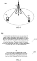
- the communication system 100 may include a network device 110, wherein the network device 110 may be a device that communicates with a terminal device 120 (or referred to as a communication terminal, or a terminal).
- the network device 110 may provide communication coverage for a specific geographical area, and may communicate with terminal devices located within the coverage area.
- the network device 110 may be a Base Transceiver Station (BTS) in a GSM system or a CDMA system, a NodeB (NB) in a WCDMA system, an Evolutional Node B (eNB or eNodeB) in an LTE system, or a radio controller in a Cloud Radio Access Network (CRAN).
- BTS Base Transceiver Station
- NB NodeB
- eNB Evolutional Node B
- CRAN Cloud Radio Access Network
- the network device may be a mobile switch center, a relay station, an access point, a vehicle-mounted device, a wearable device, a hub, a switch, a bridge, a router, a network side device in a 5G network, or a network device in a future evolved Public Land Mobile Network (PLMN), etc.
- PLMN Public Land Mobile Network
- the communication system 100 also includes at least one terminal device 120 located within the coverage range of the network device 110.
- a term "terminal device” used herein includes, but not limited to, connect through a wired circuit, for example, through a Public Switched Telephone Network (PSTN), a Digital Subscriber Line (DSL), a digital cable, a direct cable; and/or another data connection/network; and/or through a wireless interface, for example, for a cellular network, a Wireless Local Area Network (WLAN), a digital television network such as a DVB-H network, a satellite network, and an AM-FM broadcast transmitter; and/or an apparatus of another communication terminal, configured to receive/send a communication signal; and/or an Internet of Things (IoT) device.
- PSTN Public Switched Telephone Network
- DSL Digital Subscriber Line
- WLAN Wireless Local Area Network
- AM-FM broadcast transmitter AM-FM broadcast transmitter
- a terminal device configured to communicate through a wireless interface may be referred to as a "wireless communication terminal", a “wireless terminal” or a “mobile terminal”.
- the mobile terminal include, but not limited to, a satellite or cellular telephone, a Personal Communication System (PCS) terminal capable of combining a cellular wireless telephone with data processing, faxing, and data communication abilities, a PDA that may include a radio telephone, a pager, an internet/intranet access, a Web browser, a memo pad, a calendar, and/or a Global Positioning System (GPS) receiver, a conventional laptop and/or palmtop receiver or other electronic apparatuses including a radio telephone transceiver.
- PCS Personal Communication System
- GPS Global Positioning System
- the terminal device may be referred to as an access terminal, a User Device (UE), a subscriber unit, a subscriber station, a mobile station, a mobile platform, a remote station, a remote terminal, a mobile device, a user terminal, a terminal, a wireless communication device, a user agent, or a user apparatus.
- UE User Device
- the access terminal may be a cellular phone, a cordless phone, a Session Initiation Protocol (SIP) phone, a Wireless Local Loop (WLL) station, a Personal Digital Assistant (PDA), a handheld device with a wireless communication function, a computing device, or other processing devices connected to a wireless modem, a vehicle-mounted device, a wearable device, a terminal device in a 5G network, or a terminal device in a future evolved Public Land Mobile Network (PLMN), etc.
- SIP Session Initiation Protocol
- WLL Wireless Local Loop
- PDA Personal Digital Assistant
- PLMN Public Land Mobile Network
- a Device to Device (D2D) communication may be performed between the terminal devices 120.
- D2D Device to Device
- a 5G system or a 5G network may be referred to as a New Radio (NR) system or a NR network.
- NR New Radio
- FIG. 1 illustratively shows one network device and two terminal devices.
- the communication system 100 may include multiple network devices, and other quantity of terminal devices may be included within a coverage range of each network device, and this is not limited in embodiments of the present application.
- the communication system 100 may further include other network entities such as a network controller, and a mobile management entity.
- network entities such as a network controller, and a mobile management entity.
- Embodiments of the present application are not limited thereto.
- a device with a communication function in a network/system in embodiments of the present application may be referred to as a communication device.
- the communication device may include a network device 110 and terminal devices 120 which have communication functions, and the network device 110 and the terminal devices 120 may be specific devices described above, which will not be described here again.
- the communication device may also include other devices in the communication system 100, such as a network controller, a mobile management entity and other network entities. Embodiments of the present application are not limited thereto.
- FIG. 2 is a schematic flowchart of a wireless communication method 200 of an embodiment of the present application.
- the method 200 includes at least part of following contents.
- a terminal device determines at least one piece of spatial relation information from multiple pieces of spatial relation information corresponding to a target Physical Uplink Shared Channel (PUCCH) resource, wherein one piece of spatial relation information of the at least one piece of spatial relation information is used for transmitting one piece of control information of at least one piece of control information.
- PUCCH Physical Uplink Shared Channel
- receiving ends of different pieces of control information of the at least one piece of control information mentioned in an embodiment of the present application may be different TRPs.
- types of different pieces of control information of the at least one piece of control information mentioned in embodiment of the present application may be different.
- one may be ACK/NACK information and the other may be CSI (Channel State Information).
- one may be CSI based on a type I codebook, and the other may be CSI based on a type II codebook.
- control information mentioned in embodiments of the present application may refer to information transmitted on a PUCCH resource.
- control information mentioned in embodiments of the present application may include Acknowledgement (ACK)/ Negative ACKnowledgment (NACK) information of a Physical Downlink Shared Channel (PDSCH), or some pieces of channel state information used for downlink scheduling (for example, CSI), or other uplink control information required by a network side.
- ACK Acknowledgement
- NACK Negative ACKnowledgment
- PDSCH Physical Downlink Shared Channel
- CSI channel state information used for downlink scheduling
- embodiments of the present application may be used not only for transmissions of above control information, but also for transmissions of other uplink information.
- it may be used for a transmission of at least one Sounding Reference Signal (SRS), or common transmission information of SRS and control information. That is, the at least one piece of control information in embodiments of the present application may be replaced with at least one piece of uplink information.
- SRS Sounding Reference Signal
- that the target PUCCH resource corresponds to multiple pieces of spatial relation information may refer to: when an uplink transmission is performed on the target PUCCH resource, the uplink transmission may be performed based on all or part of the multiple pieces of spatial relation information.
- transmitting the control information by using the spatial relation information may refer to transmitting the control information by using a beam and/or an antenna panel (also referred as to panel) corresponding to the spatial relation information.
- beams and/or antenna panels corresponding to different pieces of spatial relation information may be different.
- the control information transmitted based on spatial relation information 1 is transmitted on antenna panel 1
- the control information transmitted based on spatial relation information 2 is transmitted on antenna panel 2.
- control information 1 may be transmitted based on beam 1 corresponding to the spatial relation information 1
- control information 2 may be transmitted based on beam 2 corresponding to the spatial relation information 2.
- the target PUCCH resource mentioned in embodiments of the present application may be one PUCCH resource, wherein the one PUCCH resource may be a periodic resource.
- the method mentioned in embodiments of the present application may be used for an uplink transmission in any period of the periodic resource.
- the target resource mentioned in embodiments of the present application may also be a PUCCH resource set, wherein the PUCCH resource set may include multiple PUCCH resources, and each PUCCH resource may be a periodic resource.
- the PUCCH resource set corresponds to multiple pieces of spatial relation information may refer to: when any resource in the PUCCH resource set is used for performing an uplink transmission, the uplink transmission may be performed based on all or part of the multiple pieces of spatial relation information.
- the multiple pieces of spatial relation information may respectively correspond to multiple TRPs in a one-by-one manner (or multiple antenna panels at the network side, and description in the embodiment of the present application is made by taking TRPs as an example).
- the spatial relation information may include a CSI-RS (Reference Signal) resource index, an SRS resource index or a Synchronization Signal and PBCH Block (SSB) index.
- CSI-RS Reference Signal
- SRS Synchronization Signal and PBCH Block
- the multiple pieces of spatial relation information may all include CSI-RS resource indexes, SRS resource indexes, or SSB indexes, that is, types of the indexes included are same.
- the types of the indexes included in the multiple pieces of spatial relation information may also be different.
- some pieces of spatial relation information include CSI-RS indexes, and other pieces of spatial relation information include SRS indexes.
- the beam corresponding to the spatial relation information may be a transmitting beam or a receiving beam of a reference signal corresponding to the spatial relation information.
- the reference signal corresponding to the spatial relation information mentioned here may refer to that the spatial relation information includes an index of the reference signal or an index of a resource of the reference signal.
- the spatial relation information includes the CSI-RS resource index
- the beam corresponding to the spatial relation information may be a beam used for receiving the CSI-RS on a resource indicated by the CSI-RS resource index.
- the spatial relation information includes the SRS resource index
- the beam corresponding to the spatial relation information may be a beam used for transmitting the SRS on a resource indicated by the SRS resource index.
- the spatial relation information includes the SSB index
- the beam corresponding to the spatial relation information may be a receiving beam used for receiving the SSB indicated by the SSB index.
- an antenna panel corresponding to the spatial relation information may be a transmitting antenna panel or a receiving antenna panel for the reference signal corresponding to the spatial relation information.
- the reference signal corresponding to the spatial relation information mentioned here may refer to that the spatial relation information includes an index of the reference signal or an index of a resource of the reference signal.
- the spatial relation information includes the CSI-RS resource index
- the antenna panel corresponding to the spatial relation information may be an antenna panel used for receiving the CSI-RS on the resource indicated by the CSI-RS resource index.
- the spatial relation information includes the SRS resource index
- the antenna panel corresponding to the spatial relation information may be an antenna panel used for transmitting the SRS on a resource indicated by the SRS resource index.
- the spatial relation information includes the SSB index
- the antenna panel corresponding to the spatial relation information may be an antenna panel used for receiving the SSB indicated by the SSB index.
- the spatial relation information includes the CSI-RS resource index
- CSI-RS resource indexes included in different pieces of spatial relation information among the multiple pieces of spatial relation information belong to different CSI-RS resource sets.
- the CSI-RS resource sets used for transmitting the CSI-RSs may be different, and the CSI-RS resource indexes included in different pieces of spatial relation information among multiple pieces of spatial relation information belong to different CSI-RS resource sets. Therefore, a piece of spatial relation information determined for one certain TRP may be associated with its corresponding CSI-RS resource set, and a beam and/or an antenna panel corresponding to the spatial relation information determined for the TRP may be a beam and/or an antenna used by a CSI-RS resource set configured for the TRP.
- the CSI-RS resources mentioned in embodiments of the present application may belong to a CSI-RS resource set, wherein the CSI-RS resource set may include multiple CSI-RS resources.
- One CSI-RS resource may be a periodic resource, or an aperiodic or quasi-persistent resource.
- used beams and/or antenna panels (which may be referred to as beams and/or antenna panels corresponding to the CSI-RS resource set here) may be the same. Beams and/or antenna panels corresponding to different CSI-RS resource sets are different.
- the same CSI-RS resource set may correspond to one beam and/or antenna panel as mentioned above, but the same CSI-RS resource set my also correspond to multiple beams and/or antenna panels (for example, there are multiple CSI-RS resources, and their corresponding beams and/or antenna panels are different from each other). In this case, beams and/or antenna panels corresponding to different CSI-RS resource sets may also be completely different (that is, a common beam and/or antenna panel does not exist).
- the spatial relation information includes the SRS resource index
- SRS resource indexes included in different pieces of spatial relation information among the multiple pieces of spatial relation information belong to different SRS resource sets.
- the SRS resource sets of the SRSs transmitted by the terminal device may be different (it may be understood here that different TRPs correspond to different SRS resource sets), and the SRS resource indexes included in different pieces of spatial relation information among the multiple spatial relation information belong to different SRS resource sets. Therefore, the spatial relation information determined for one certain TRP may be associated with its corresponding SRS resource set, and the beam and/or antenna panel corresponding to the spatial relation information determined for the TRP may be the beam and/or the antenna panel used by the terminal device for transmitting the SRSs for SRS resources in a SRS resource set configured for the TRP.
- the SRS resources mentioned in embodiments of the present application may belong to the SRS resource set, and one SRS resource may be a periodic resource, or an aperiodic or quasi-persistent resource.
- used beams and/or antenna panels (which may be referred to as beams and/or antenna panels corresponding to the SRS resource set here) may be the same. Beams and/or antenna panels corresponding to different SRS resource sets are different.
- the same SRS resource set may correspond to one beam and/or antenna panel as mentioned above, but the same SRS resource set may also correspond to multiple beams and/or antenna panels (for example, there are multiple SRS resources, and their corresponding beams and/or antenna panels are different from each other). In this case, beams and/or antenna panels corresponding to different SRS resource sets may also be completely different (that is, a common beam and/or antenna panel does not exist).
- the spatial relation information includes SSB indexes
- different pieces of cell information are carried by SSBs corresponding to SSB indexes included in different pieces of spatial relation information among the multiple pieces of spatial relation information
- the cell information mentioned here includes but is not limited to cell ID.
- the cell information may also be any information carried by a PBCH in an SSB.
- SSBs may be used for sending different cell information, wherein different cell information indicates that a SSB comes from a different TRP, therefore the spatial relation information determined for one certain TRP may be associated with its corresponding cell information, and the beam and/or antenna panel corresponding to the spatial relation information determined for the TRP may be a beam and/or an antenna panel used by the TRP for transmitting the SSB carrying corresponding cell information.
- different SSB indexes in embodiments of the present application may correspond to different beams and/or antenna panels, that is, SSBs corresponding to the SSB indexes may be transmitted using different beams and/or antenna panels. Or, SSBs carrying different pieces of cell information may correspond to different beams and/or antenna panels.
- a beam used for transmitting signals may also be referred to as a spatial domain transmission filter
- a beam used for receiving signals may also be referred to as a spatial domain reception filter, or both of them are simply referred to as spatial domain filters.
- a network device may configure the above-mentioned spatial relation information for the terminal device.
- the network device may configure multiple corresponding spatial relation information for the target PUCCH resource.
- the target PUCCH resource is a PUCCH resource
- multiple pieces of spatial relation information may be configured for the PUCCH resource, and if the target PUCCH resource is a PUCCH resource set, the multiple pieces of spatial relation information may be configured for the PUCCH resource set.
- the network device may configure multiple pieces of spatial relation information for the target PUCCH resource through Radio Resource Control (RRC) and/or Media Access Control (MAC) signaling.
- RRC Radio Resource Control
- MAC Media Access Control
- the network device may send the RRC signaling to the terminal device, wherein the RRC signaling may configure the above-mentioned multiple pieces of spatial relation information for the target PUCCH resource.
- the number of the multiple pieces of spatial relation information indicated by the RRC signaling may be less than or equal to a preset value.
- the preset value may be configured by the network device to the terminal device (may be configured based on the number of antenna panels and/or beams that may be used by the terminal device which is reported by the terminal device), or may be preset on the terminal device based on a protocol, or may be determined by the terminal device and network device respectively based on the number of antenna panels and/or beams that may be used by the terminal device.
- the network device may send the RRC signaling to the terminal device, wherein the RRC signaling is used for configuring a candidate set of spatial relation information. And the network device sends a MAC signaling to the terminal device, wherein the MAC signaling is used for indicating the multiple pieces of spatial relation information in the candidate set.
- the number of the spatial relation information included in the candidate set may be greater than the above-mentioned number of the multiple pieces of spatial relation information.
- the terminal device may semi-statically configure a large number of spatial relation information through the RRC signaling, and indicate in the MAC signaling the spatial relation information needed to be used.
- an amount of spatial relation information indicated by the RRC signaling may be greater than a preset value.
- the preset value may be configured by the network device to the terminal device (may be configured based on the number of antenna panels and/or beams that may be used by the terminal device which is reported by the terminal device), or preset on the terminal device based on a protocol, or determined by the terminal device and network device respectively based on the number of antenna panels and/or beams that may be used by the terminal device.
- the MAC signaling when the number of the spatial relation information indicated by the RRC signaling is less than or equal to the preset value, the MAC signaling may not be used to indicate the multiple spatial relation information. When the number of the spatial relation information indicated by the RRC signaling is greater than the preset value, the MAC signaling is used to indicate the multiple pieces of spatial relation information.
- the network side may send the MAC signaling to the terminal device, wherein the MAC signaling may configure the above multiple pieces of spatial relation information for the target PUCCH resource. At this time, there is no longer need to send the RRC signaling to indicate the multiple pieces of spatial relation information.
- an indication field of PUCCH spatial relation information in a MAC layer signaling contains N bits, wherein N is a size of the above candidate set, and each bit corresponds to one piece of spatial relation information in the candidate set, and the multiple pieces of spatial relation information are spatial relation information corresponding to bits with value 1 in the indication field.
- the network side preconfigures K candidate sets through the RRC signaling (wherein the K candidate sets may commonly be equivalent to the candidate sets of spatial relation information mentioned above), and then indicates one piece of spatial relation information from each candidate set respectively through the MAC layer signaling, so as to obtain K pieces of spatial relation information.
- the PUCCH spatial relation information indication field of the MAC may contain K*M bits, wherein M is a size of a candidate set.
- a first control information mentioned below may be any one control information among the multiple pieces of control information, and a first spatial relation information may be spatial relation information for transmitting the first control information.
- the terminal device may determine the first spatial relation information for the first control information in the at least one pieces of control information from the multiple pieces of spatial relation information according to at least one of the following: a reporting configuration of the first control information, content of the first control information, a downlink data channel (specifically PDSCH) corresponding to the first control information (for example, a scheduling order of the downlink data channel, etc.), and a control channel for scheduling the downlink data channel corresponding to the first control information.
- a reporting configuration of the first control information for example, content of the first control information, a downlink data channel (specifically PDSCH) corresponding to the first control information (for example, a scheduling order of the downlink data channel, etc.)
- a downlink data channel specifically PDSCH
- a control channel for scheduling the downlink data channel corresponding to the first control information for example, a scheduling order of the downlink data channel, etc.
- the reporting configuration of the first control information may indicate configuration information used for the terminal to obtain and report the first control information. For example, a resource occupied by a downlink reference signal used for measuring the first control information, a measurement mode of the first control information and how to report the first control information.
- the first control information may be a CSI, so the first spatial relation information is determined based on a CSI reporting configuration corresponding to the first control information.
- the CSI reporting configuration includes a configuration for measuring and obtaining a downlink reference signal of the CSI, a measurement mode of the CSI, a reporting mode of the CSI and a resource used for reporting the CSI, etc.
- the first spatial relation information may be determined based on a configuration ID of the CSI reporting configuration corresponding to the first control information, a configuration set to which the CSI reporting configuration corresponding to the first control information belongs, or indication information in the CSI reporting configuration corresponding to the first control information.
- a target PUCCH resource may correspond to multiple CSI reporting configurations, and each CSI transmitted on the target PUCCH resource may correspond to one of the multiple CSI reporting configurations.
- that a target PUCCH resource corresponds to the multiple CSI reporting configurations mentioned here refers to that CSI corresponding to the multiple CSI reporting configurations respectively may be sent on the target PUCCH resource.
- one piece of control information may correspond to one CSI reporting configuration may refer to that the one piece of control information may be transmitted on the target PUCCH resource by using the one CSI reporting configuration.
- the indication information in the CSI reporting configuration corresponding to the first control information may be any one piece of indication information in the CSI reporting configuration.
- a downlink reference signal configuration for measurement a CSI reporting resource configuration, a TRP indication corresponding to the CSI reporting, spatial relation information indication corresponding to the CSI reporting or beam indication corresponding to the CSI reporting, etc.
- the reporting resources in above reporting configuration may include the target PUCCH resource.
- the terminal sequentially determines the spatial relation information corresponding to each CSI reporting configuration from the multiple pieces of spatial relation information according to an order of CSI reporting configuration IDs. For example, if there are 2 CSI reporting configurations including the target PUCCH resource, a CSI reporting configuration with a smaller configuration ID corresponds to a first piece of spatial relation information among the multiple pieces of spatial relation information, and a CSI reporting configuration with a greater configuration ID corresponds to a second piece of spatial relation information among the multiple pieces of spatial relation information.
- the terminal determines multiple pieces of corresponding spatial relation information according to a configuration set to which the terminal belongs. For example, a first CSI configuration set corresponds to the first piece of spatial relation information among the multiple pieces of spatial relation information, and a second CSI configuration set corresponds to the second spatial relation information among the multiple pieces of spatial relation information.
- Each configuration set mentioned here may include multiple CSI configurations.
- the terminal determines CSI corresponding to a certain TRP according to the CSI reporting configuration corresponding to the TRP, determines a target PUCCH resource for transmitting the CSI according to the CSI reporting configuration, and determines the spatial relation information based on the CSI reporting configuration.
- the CSI when the CSI is being reported, it may be reported by using its corresponding CSI reporting configuration.
- the first spatial relation information is determined based on whether content of the first control information is acknowledgement/negative acknowledgement ACK/NACK feedback information or CSI.
- the terminal device may determine the spatial relation information according to whether the ACK/NACK information or the CSI needs to be reported, wherein spatial relation information corresponding to the ACK/NACK may be different from spatial relation information corresponding to the CSI.
- the spatial relation information used for reporting the ACK/NACK is spatial relation information 1
- the spatial relation information used for sending the CSI is spatial relation information 2.
- the first spatial relation information is determined based on a spatial relation information indication included in the first control information.
- control information may include an indication field, wherein the indication field may indicate which piece of spatial relation information needs to be used, so that which piece of spatial relation information to be used may be determined according to a spatial relation information indication of the indication field.
- a downlink channel corresponding to the first control information is a first physical downlink shared channel (PDSCH), and the first control information is ACK/NACK feedback information of the first PDSCH.
- PDSCH physical downlink shared channel
- the first spatial relation information is determined from the multiple pieces of spatial relation information based on a scheduling order of the first PDSCH and/or a resource index occupied by the control channel for scheduling the first PDSCH.
- the scheduling order of the PDSCH mentioned here may be a scheduling order of the first PDSCH in at least one PDSCH, wherein the at least one PDSCH is all PDSCHs that need to transmit NACK/ACK on the target PUCCH resource at present, and the spatial relation information used by PDSCHs with different scheduling orders for sending their corresponding feedback information may be different.
- the resource index of the PDSCH mentioned here may indicate a resource set to which a resource of the PDSCH belong.
- a PDSCH scheduled by a PDCCH in PDCCH resource set 1 corresponds to the first piece of spatial relation information among the multiple pieces of spatial relation information
- a PDSCH scheduled by a PDCCH in PDCCH resource set 2 corresponds to the second piece of spatial relation information among the multiple pieces of spatial relation information.
- a PDSCH corresponding to the first control information is a first PDSCH
- the first control information is ACK/NACK feedback information of the first PDSCH
- the first spatial relation information is determined based on transport block information (which may be a transport block configuration for example) used by the first PDSCH.
- the first spatial relation information may be determined based on a transport block index used by the first PDSCH.
- the first spatial relation information is a first piece of spatial relation information of the 2 pieces of spatial relation information when the transport block index used by the first PDSCH is transport block 1.
- the first spatial relation information is a second piece of spatial relation information of the 2 pieces of spatial relation information when the transport block index used by the first PDSCH is transport block 2.
- the transport block index used by the PDSCH is determined according to a transport block configuration in DCI for scheduling the PDSCH.
- the DCI may indicate which transport block is currently enabled for a data transmission.
- the first spatial relation information may also be determined based on other information of the transport block (for example, other transport block configurations).
- the PDSCH corresponding to the first control information is the first PDSCH
- the first control information is the ACK/NACK feedback information of the first PDSCH
- the first spatial relation information is determined based on spatial relation information indication in downlink control information (DCI) for scheduling the first PDSCH.
- DCI downlink control information
- the DCI for scheduling the PDSCH may contain indication information, wherein the indication information is used for indicating which piece of information among multiple pieces of spatial relation information corresponding to the target PUCCH resource is used for transmitting the ACK/NACK corresponding to the PDSCH.
- the target PUCCH resource may correspond to 2 pieces of spatial relation information. If the bit value in the indication field of the spatial relation information of the DCI for scheduling the PDSCH is 0, the first piece of spatial relation information may be used for transmitting the ACK or NACK of the PDSCH. If the bit value in the indication field of the spatial relation information of the DCI for scheduling the PDSCH is 1, the second piece of spatial relation information may be used for transmitting the ACK or NACK of the PDSCH.
- the terminal device transmits the at least one piece of control information on the target PUCCH resource by using the determined at least one piece of spatial relation information.
- the terminal device determines an antenna panel and/or a beam corresponding to the first spatial relation information in the at least one piece of spatial relation information, and transmits the first control information in the at least one piece of control information on the target PUCCH resource by using the antenna panel and/or the beam corresponding to the first spatial relation information.
- the spatial relation information may also be associated with other transmission factors besides the panel and/or the beam, which is not specifically limited in the embodiment of the present application.
- the panel and/or the beam may be determined not based on the spatial relation information.
- the terminal device determines an antenna panel corresponding to each piece of spatial relation information in the at least one piece of spatial relation information, and respectively transmits the control information on the corresponding antenna panel based on each piece of spatial relation information.
- the terminal determines one corresponding antenna panel according to one piece of the spatial relation information, and determines one corresponding beam based on the spatial relation information, so that the determined beam is used to transmit the control information on the determined antenna panel.
- the terminal device transmits the control information based on different pieces of spatial relation information among the multiple pieces of spatial relation information, used antenna panels and/or beams are different.
- the antenna panel and/or the beam corresponding to the spatial relation information are an antenna panel and/or a beam used by the terminal device for sending or receiving the reference signal indicated by the spatial relation information.
- the PUCCH resource may correspond to multiple pieces of spatial relation information.
- different pieces of spatial relation information may be used for control information of different receiving ends (which specifically may be TPRs), so that the PUCCH resource may be shared by multiple pieces of control information, and the resource overhead may be saved.
- the terminal device may simultaneously report ACK/NACK or CSI respectively corresponding to multiple TRPs, so as to support downlink NC-JT better and improve a throughput of a downlink transmission.
- the terminal device may use a same PUCCH resource to transmit PUCCHs to different TRPs by using different antenna panels and/or beams, so that different TRPs may share the same PUCCH resource, thus saving the cost of PUCCH resource.
- FIG. 3 is a schematic block diagram of a terminal device 300 according to an embodiment of the present application. As shown in FIG. 3 , the terminal device 300 includes a processing unit 310 and a communication unit 320.
- the processing unit 310 is configured to determine at least one piece of spatial relation information from multiple pieces of spatial relation information corresponding to a target physical uplink control channel (PUCCH) resource, wherein one piece of spatial relation information of the at least one piece of spatial relation information is used for transmitting one piece of control information of at least one piece of control information.
- PUCCH physical uplink control channel
- the communication unit 320 is configured to transmit the at least one piece of control information on the target PUCCH resource by using the at least one piece of spatial relation information determined by the processing unit 310.
- the processing unit 310 is further configured to: determine a first spatial relation information for a first control information in the at least one piece of control information from the multiple pieces of spatial relation information, according to at least one of the following: a reporting configuration of the first control information, content of the first control information, a physical downlink shared channel (PDSCH) corresponding to the first control information, and a control channel for scheduling the PDSCH corresponding to the first control information.
- a reporting configuration of the first control information a reporting configuration of the first control information
- content of the first control information a physical downlink shared channel (PDSCH) corresponding to the first control information
- PDSCH physical downlink shared channel
- the first control information is channel state information (CSI)
- the first spatial relation information is determined based on a CSI reporting configuration corresponding to the first control information.
- the first spatial relation information is determined based on a configuration ID of the CSI reporting configuration corresponding to the first control information, a configuration set to which the CSI reporting configuration corresponding to the first control information belongs, or indication information in the CSI reporting configuration corresponding to the first control information.
- a reporting resource configuration in the reporting configuration includes the target PUCCH resource.
- the first spatial relation information is determined based on whether content of the first control information is acknowledgement/negative acknowledgement ACK/NACK feedback information or the CSI. Or, the first spatial relation information is determined based on spatial relation information indication included in the first control information.
- the PDSCH corresponding to the first control information is a first PDSCH
- the first control information is ACK/NACK feedback information of the first PDSCH
- the first spatial relation information is determined from the multiple pieces of spatial relation information based on a scheduling order of the first PDSCH and/or a resource index occupied by the control channel scheduling the first PDSCH.
- the PDSCH corresponding to the first control information is the first PDSCH
- the first control information is the ACK/NACK feedback information of the first PDSCH
- the first spatial relation information is determined based on a transport block index used by the first PDSCH.
- the PDSCH corresponding to the first control information is the first PDSCH
- the first control information is the ACK/NACK feedback information of the first PDSCH
- the first spatial relation information is determined based on the spatial relation information indication in the downlink control information (DCI) for scheduling the first PDSCH.
- DCI downlink control information
- the communication unit 320 is further configured to: receive the multiple pieces of spatial relation information configured by a network side for the target PUCCH resource through radio resource control (RRC) signaling and/or media access control (MAC) signaling.
- RRC radio resource control
- MAC media access control
- the communication unit 320 is further configured to: receive the RRC signaling sent by the network side, wherein the RRC signaling is used for configuring a candidate set of the spatial relation information; and receive the MAC signaling sent by the network side, wherein the MAC signaling is used for indicating the multiple pieces of spatial relation information from the candidate set.
- the spatial relation information includes a channel state information reference signal CSI-RS resource index, a sounding reference signal (SRS) resource index or a synchronization signal block (SSB) index.
- CSI-RS channel state information reference signal
- SRS sounding reference signal
- SSB synchronization signal block
- the spatial relation information includes the CSI-RS resource index
- CSI-RS resource indexes included in different pieces of spatial relation information the multiple pieces of spatial relation information belong to different CSI-RS resource sets.
- the spatial relation information includes the SRS resource index
- SRS resource indexes included in different pieces of spatial relation information in the multiple pieces of spatial relation information belong to different SRS resource sets.
- the spatial relation information includes the SSB indexes
- SSBs corresponding to SSB indexes included in different pieces of spatial relation information in the multiple pieces of spatial relation information carry different cell information.
- the processing unit 310 is further configured to:
- antenna panels and/or beams used are different.
- an antenna panel and/or a beam corresponding to the spatial relation information is an antenna panel and/or a beam used by the terminal device for sending or receiving a reference signal indicated by the spatial relation information.
- terminal device 300 may implement a corresponding operation implemented by the terminal device in the above method 200, which will not be described in detail herein for the sake of brevity.
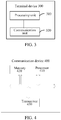
- FIG. 4 is a schematic block diagram of a terminal 400 of an embodiment of the present application.
- a terminal device 400 shown in FIG. 4 includes a processor 410.
- the processor 410 may call and run a computer program from a memory to implement a method in an embodiment of the present application.
- the terminal device 400 may further include a memory 420, wherein the processor 410 may call and run a computer program from the memory 420 to implement a method in an embodiment of the present application.
- the memory 420 may be a separate device independent of the processor 410 or may be integrated in the processor 410.
- the terminal device 400 may further include a transceiver 430.
- the processor 410 may control the transceiver 430 to communicate with other devices.
- the transceiver 430 may send information or data to other devices or receive information or data sent by other devices.
- the transceiver 430 may include a transmitter and a receiver.
- the transceiver 430 may further include antennas, and a number of antennas may be one or more.
- the terminal 400 may implement the corresponding procedures implemented by a terminal device in a method 200 of embodiments of the present application, which will not be repeated here for the sake of brevity.
- FIG. 5 is a schematic block diagram of a chip according to an embodiment of the present application.
- a chip 500 shown in FIG. 5 includes a processor 510, wherein the processor 510 may call and run a computer program from a memory to implement a method in embodiments of the present application.
- the chip 500 may further include a memory 520, wherein the processor 510 may call and run a computer program from the memory 520 to implement a method in embodiments of the present application.
- the memory 520 may be a separate device independent of the processor 510 or may be integrated in the processor 510.
- the chip 500 may further include an input interface 530, wherein the processor 510 may control the input interface 530 to communicate with other devices or chips.
- the input interface 530 may obtain information or data sent by other devices or chips.
- the chip 500 may further include an output interface 540, wherein the processor 510 may control the output interface 540 to communicate with other devices or chips.
- the output interface 540 may output information or data to other devices or chips.
- the chip may be applied in a terminal device of embodiments of the present application, and the chip may implement corresponding procedures implemented by a terminal device in various methods of embodiments of the present application, which will not be repeated here for sake of brevity.
- the chip may be applied in a network device of embodiments of the present application, and the chip may implement corresponding procedures implemented by the network device in various methods of embodiments of the present application, which will not be repeated here for sake of brevity.
- chip mentioned in embodiments of the present application may be referred to as a system-level chip, a system chip, a chip system or a system-on-chip, etc.
- FIG. 6 is a schematic block diagram of a communication system 600 provided by an embodiment of the present application. As shown in FIG. 6 , the communication system 600 may include a terminal device 610 and a network device 620.
- the terminal device 610 may be configured to implement corresponding functions implemented by the terminal device in above-mentioned method
- the network device 620 may be configured to implement corresponding functions implemented by the network device in above-mentioned method, which will not be repeated here for sake of brevity.
- the processor above-mentioned may be a general purpose processor, a digital signal processor (DSP), a field programmable gate array (FPGA), an application specific integrated circuit (ASIC) or other programmable logic devices, a transistor logic device, or a discrete hardware component, etc.
- DSP digital signal processor
- FPGA field programmable gate array
- ASIC application specific integrated circuit
- the general-purpose processor mentioned above may be a microprocessor or any conventional processor, etc.
- Non-volatile memory may be a read-only memory (ROM), a programmable ROM (PROM), an erasable PROM (EPROM), an electrically erasable EPROM (EEPROM), or a flash memory.
- ROM read-only memory
- PROM programmable ROM
- EPROM erasable PROM
- EEPROM electrically erasable EPROM
- flash memory a flash memory.
- the volatile memory may be a Random Access Memory (RAM).
- the memory in embodiments of the present application also may be a Static RAM (SRAM), a Dynamic RAM (DRAM), a Synchronous DRAM (SDRAM), a Double Data Rate SDRAM (DDR SDRAM), an Enhanced SDRAM (ESDRAM), a Synchlink DRAM (SLDRAM), a Direct Rambus RAM (DR RAM), etc.
- SRAM Static RAM
- DRAM Dynamic RAM
- SDRAM Synchronous DRAM
- DDR SDRAM Double Data Rate SDRAM
- ESDRAM Enhanced SDRAM
- SLDRAM Synchlink DRAM
- DR RAM Direct Rambus RAM
- the disclosed systems, apparatuses and methods may be implemented in other ways.
- the apparatus embodiments described above are only illustrative, for example, the division of the units is only a logical function division, and there may be other division manners in actual embodiment, for example, multiple units or components may be combined or integrated into another system, or some features may be ignored or not executed.
- the mutual coupling or direct coupling or communication connection shown or discussed may be indirect coupling or communication connection through some interface, apparatus or unit, and may be in electrical, mechanical or other forms.
- the unit described as a separate component may or may not be physically separated, and the component shown as a unit may or may not be a physical unit, i.e., it may be located in one place or may be distributed over multiple network units. Some or all of the units may be selected according to actual needs to achieve the purpose of the embodiments.
- various functional units in various embodiments of the present application may be integrated in one processing unit, or the various units may be physically present separately, or two or more units may be integrated in one unit.
- the functions may be stored in a computer readable storage medium if realized in a form of software functional units and sold or used as a separate product.
- the technical solution of the present application in essence, or the part contributing to the prior art, or the part of the technical solution, may be embodied in the form of a software product stored in a storage medium, including a number of instructions for causing a computer device (which may be a personal computer, a server, or a network device and the like) to perform all or part of the acts of the method described in various embodiments of the present application.
- the foregoing storage medium includes: any medium that may store program code, such as a USB flash drive, a removable hard disk, a read-only memory (Read-Only Memory, ROM), a random access memory (Random Access Memory, RAM), a magnetic disk, or an optical disc.
- program code such as a USB flash drive, a removable hard disk, a read-only memory (Read-Only Memory, ROM), a random access memory (Random Access Memory, RAM), a magnetic disk, or an optical disc.
Landscapes
- Engineering & Computer Science (AREA)
- Signal Processing (AREA)
- Computer Networks & Wireless Communication (AREA)
- Power Engineering (AREA)
- Mobile Radio Communication Systems (AREA)
Applications Claiming Priority (2)
| Application Number | Priority Date | Filing Date | Title |
|---|---|---|---|
| CN2018107543 | 2018-09-26 | ||
| PCT/CN2018/109360 WO2020062318A1 (fr) | 2018-09-26 | 2018-10-08 | Procédé de communication sans fil et dispositif terminal |
Publications (2)
| Publication Number | Publication Date |
|---|---|
| EP3836593A1 true EP3836593A1 (fr) | 2021-06-16 |
| EP3836593A4 EP3836593A4 (fr) | 2021-11-17 |
Family
ID=69950977
Family Applications (1)
| Application Number | Title | Priority Date | Filing Date |
|---|---|---|---|
| EP18935943.3A Withdrawn EP3836593A4 (fr) | 2018-09-26 | 2018-10-08 | Procédé de communication sans fil et dispositif terminal |
Country Status (5)
| Country | Link |
|---|---|
| US (1) | US20210195627A1 (fr) |
| EP (1) | EP3836593A4 (fr) |
| CN (2) | CN116113052B (fr) |
| TW (1) | TW202019210A (fr) |
| WO (1) | WO2020062318A1 (fr) |
Families Citing this family (7)
| Publication number | Priority date | Publication date | Assignee | Title |
|---|---|---|---|---|
| EP4593302A3 (fr) * | 2020-02-13 | 2025-08-06 | Telefonaktiebolaget LM Ericsson (publ) | Améliorations de fiabilité de pusch à multiples trps |
| JP7554834B2 (ja) | 2020-02-13 | 2024-09-20 | テレフオンアクチーボラゲット エルエム エリクソン(パブル) | 複数の関連付けられたnzp csi-rsを用いた非コードブックベースのマルチtrp puschの信頼性 |
| EP4131796A4 (fr) * | 2020-03-24 | 2024-05-01 | LG Electronics Inc. | Procédé et appareil de transmission ou de réception en liaison montante d'après un paramètre spécial dans un système de communication sans fil |
| US11711787B2 (en) * | 2020-04-09 | 2023-07-25 | Comcast Cable Communications, Llc | Transmission and reception configuration and signaling |
| WO2021258316A1 (fr) * | 2020-06-24 | 2021-12-30 | Zte Corporation | Gestion de configurations pour la génération d'informations d'état de canal |
| CN116326071B (zh) * | 2020-10-15 | 2025-03-18 | 苹果公司 | 高频波束切换 |
| CN115811761A (zh) * | 2021-09-13 | 2023-03-17 | 维沃移动通信有限公司 | 资源选择方法、装置及终端 |
Family Cites Families (12)
| Publication number | Priority date | Publication date | Assignee | Title |
|---|---|---|---|---|
| KR20150013443A (ko) * | 2012-05-22 | 2015-02-05 | 엘지전자 주식회사 | Harq ack/nack 전송 방법 및 무선기기 |
| CN104811267A (zh) * | 2014-01-29 | 2015-07-29 | 上海贝尔股份有限公司 | 协同多点传输的方法 |
| CN106257856B (zh) * | 2015-06-19 | 2021-02-02 | 北京三星通信技术研究有限公司 | 一种传输上行控制信息的方法 |
| US10631329B2 (en) * | 2016-08-12 | 2020-04-21 | Qualcomm Incorporated | Non-coherent joint transmission techniques |
| CN108282285B (zh) * | 2017-01-05 | 2020-06-02 | 华为技术有限公司 | 信号传输方法和装置 |
| CN108282212B (zh) * | 2017-01-06 | 2022-06-14 | 华为技术有限公司 | 一种信道状态信息处理的方法、装置和系统 |
| CN108401303B (zh) * | 2017-02-04 | 2021-07-20 | 华为技术有限公司 | 终端、网络设备和通信方法 |
| WO2019138555A1 (fr) * | 2018-01-12 | 2019-07-18 | 株式会社Nttドコモ | Terminal d'utilisateur et procédé de communication sans fil |
| US10560901B2 (en) * | 2018-02-16 | 2020-02-11 | Lenovo (Singapore) Pte. Ltd. | Method and apparatus having power control for grant-free uplink transmission |
| US20190297603A1 (en) * | 2018-03-23 | 2019-09-26 | Samsung Electronics Co., Ltd. | Method and apparatus for beam management for multi-stream transmission |
| CN112204899B (zh) * | 2018-06-08 | 2024-01-19 | 汉尼拔Ip有限责任公司 | 用于多trp传输的方法和ue |
| US20210345390A1 (en) * | 2018-08-09 | 2021-11-04 | Ntt Docomo, Inc. | User terminal and radio communication method |
-
2018
- 2018-10-08 WO PCT/CN2018/109360 patent/WO2020062318A1/fr not_active Ceased
- 2018-10-08 EP EP18935943.3A patent/EP3836593A4/fr not_active Withdrawn
- 2018-10-08 CN CN202310082265.XA patent/CN116113052B/zh active Active
- 2018-10-08 CN CN201880097280.9A patent/CN112690013A/zh active Pending
-
2019
- 2019-09-26 TW TW108134957A patent/TW202019210A/zh unknown
-
2021
- 2021-03-08 US US17/195,183 patent/US20210195627A1/en not_active Abandoned
Also Published As
| Publication number | Publication date |
|---|---|
| CN116113052B (zh) | 2024-09-17 |
| US20210195627A1 (en) | 2021-06-24 |
| EP3836593A4 (fr) | 2021-11-17 |
| TW202019210A (zh) | 2020-05-16 |
| WO2020062318A1 (fr) | 2020-04-02 |
| CN116113052A (zh) | 2023-05-12 |
| CN112690013A (zh) | 2021-04-20 |
Similar Documents
| Publication | Publication Date | Title |
|---|---|---|
| EP3918830B1 (fr) | Procédé et équipement d'utilisateur permettant de déterminer un niveau de priorité d'un rapport de csi | |
| US20210195627A1 (en) | Wireless Communication Method and Terminal Device | |
| US12309791B2 (en) | Method and device for transmitting uplink signal | |
| US12150071B2 (en) | Method for transmitting sidelink data, terminal device, and network device | |
| US11950265B2 (en) | Data transmission method, terminal device, and network device | |
| EP3644657A1 (fr) | Procédé et dispositif de régulation de puissance, et terminal | |
| US11943782B2 (en) | Data channel transmission method and terminal device | |
| US20220104208A1 (en) | Csi reporting method and terminal device | |
| CN112703779A (zh) | 一种上行传输的功率控制方法及终端设备 | |
| EP3829208B1 (fr) | Procédé de rapport de signal, dispositif terminal et dispositif de réseau | |
| CN112970294A (zh) | 传输信号的方法、终端设备和网络设备 | |
| EP3648391B1 (fr) | Procédé et dispositif de transmission d'informations | |
| WO2021168709A1 (fr) | Procédés et appareils de rapport et de réception de csi, dispositif terminal et dispositif de réseau | |
| US11758541B2 (en) | Information transmission method, terminal device and network device | |
| EP4040816A1 (fr) | Procédé de communication, dispositif terminal et dispositif de réseau | |
| CN114258654A (zh) | 用于传输信道状态信息的方法及设备 | |
| KR20210047324A (ko) | 정보 전송 방법, 장치 및 저장 매체 | |
| CN112567822A (zh) | 一种上行信号传输方法、终端和存储介质 | |
| US12149460B2 (en) | Wireless communication method, network device, and terminal device | |
| US12426054B2 (en) | Channel processing method and electronic device | |
| AU2018447235B2 (en) | Uplink control information determination method and communication device | |
| CA3105883C (fr) | Procede de determination d'informations de commande de liaison montante et dispositif de communication | |
| CN119896004A (zh) | 一种无线通信方法及设备、存储介质 |
Legal Events
| Date | Code | Title | Description |
|---|---|---|---|
| STAA | Information on the status of an ep patent application or granted ep patent |
Free format text: STATUS: THE INTERNATIONAL PUBLICATION HAS BEEN MADE |
|
| PUAI | Public reference made under article 153(3) epc to a published international application that has entered the european phase |
Free format text: ORIGINAL CODE: 0009012 |
|
| STAA | Information on the status of an ep patent application or granted ep patent |
Free format text: STATUS: REQUEST FOR EXAMINATION WAS MADE |
|
| 17P | Request for examination filed |
Effective date: 20210309 |
|
| AK | Designated contracting states |
Kind code of ref document: A1 Designated state(s): AL AT BE BG CH CY CZ DE DK EE ES FI FR GB GR HR HU IE IS IT LI LT LU LV MC MK MT NL NO PL PT RO RS SE SI SK SM TR |
|
| A4 | Supplementary search report drawn up and despatched |
Effective date: 20211018 |
|
| RIC1 | Information provided on ipc code assigned before grant |
Ipc: H04L 5/00 20060101ALI20211012BHEP Ipc: H04W 24/00 20090101AFI20211012BHEP |
|
| DAV | Request for validation of the european patent (deleted) | ||
| DAX | Request for extension of the european patent (deleted) | ||
| STAA | Information on the status of an ep patent application or granted ep patent |
Free format text: STATUS: EXAMINATION IS IN PROGRESS |
|
| 17Q | First examination report despatched |
Effective date: 20240306 |
|
| STAA | Information on the status of an ep patent application or granted ep patent |
Free format text: STATUS: THE APPLICATION HAS BEEN WITHDRAWN |
|
| 18W | Application withdrawn |
Effective date: 20240409 |