EP3836677B1 - Procédé d'indication de bande passante, terminal et appareil de réseau - Google Patents
Procédé d'indication de bande passante, terminal et appareil de réseau Download PDFInfo
- Publication number
- EP3836677B1 EP3836677B1 EP19846435.6A EP19846435A EP3836677B1 EP 3836677 B1 EP3836677 B1 EP 3836677B1 EP 19846435 A EP19846435 A EP 19846435A EP 3836677 B1 EP3836677 B1 EP 3836677B1
- Authority
- EP
- European Patent Office
- Prior art keywords
- bandwidth resource
- terminal
- bandwidth
- indication information
- bwp
- Prior art date
- Legal status (The legal status is an assumption and is not a legal conclusion. Google has not performed a legal analysis and makes no representation as to the accuracy of the status listed.)
- Active
Links
Images

Classifications
-
- H—ELECTRICITY
- H04—ELECTRIC COMMUNICATION TECHNIQUE
- H04L—TRANSMISSION OF DIGITAL INFORMATION, e.g. TELEGRAPHIC COMMUNICATION
- H04L27/00—Modulated-carrier systems
- H04L27/26—Systems using multi-frequency codes
- H04L27/2601—Multicarrier modulation systems
- H04L27/2602—Signal structure
- H04L27/26025—Numerology, i.e. varying one or more of symbol duration, subcarrier spacing, Fourier transform size, sampling rate or down-clocking
-
- H—ELECTRICITY
- H04—ELECTRIC COMMUNICATION TECHNIQUE
- H04L—TRANSMISSION OF DIGITAL INFORMATION, e.g. TELEGRAPHIC COMMUNICATION
- H04L5/00—Arrangements affording multiple use of the transmission path
- H04L5/003—Arrangements for allocating sub-channels of the transmission path
- H04L5/0048—Allocation of pilot signals, i.e. of signals known to the receiver
- H04L5/0051—Allocation of pilot signals, i.e. of signals known to the receiver of dedicated pilots, i.e. pilots destined for a single user or terminal
-
- H—ELECTRICITY
- H04—ELECTRIC COMMUNICATION TECHNIQUE
- H04L—TRANSMISSION OF DIGITAL INFORMATION, e.g. TELEGRAPHIC COMMUNICATION
- H04L5/00—Arrangements affording multiple use of the transmission path
- H04L5/003—Arrangements for allocating sub-channels of the transmission path
- H04L5/0053—Allocation of signalling, i.e. of overhead other than pilot signals
-
- H—ELECTRICITY
- H04—ELECTRIC COMMUNICATION TECHNIQUE
- H04L—TRANSMISSION OF DIGITAL INFORMATION, e.g. TELEGRAPHIC COMMUNICATION
- H04L5/00—Arrangements affording multiple use of the transmission path
- H04L5/0091—Signalling for the administration of the divided path, e.g. signalling of configuration information
- H04L5/0092—Indication of how the channel is divided
-
- H—ELECTRICITY
- H04—ELECTRIC COMMUNICATION TECHNIQUE
- H04L—TRANSMISSION OF DIGITAL INFORMATION, e.g. TELEGRAPHIC COMMUNICATION
- H04L5/00—Arrangements affording multiple use of the transmission path
- H04L5/0091—Signalling for the administration of the divided path, e.g. signalling of configuration information
- H04L5/0094—Indication of how sub-channels of the path are allocated
-
- H—ELECTRICITY
- H04—ELECTRIC COMMUNICATION TECHNIQUE
- H04L—TRANSMISSION OF DIGITAL INFORMATION, e.g. TELEGRAPHIC COMMUNICATION
- H04L5/00—Arrangements affording multiple use of the transmission path
- H04L5/0091—Signalling for the administration of the divided path, e.g. signalling of configuration information
- H04L5/0096—Indication of changes in allocation
- H04L5/0098—Signalling of the activation or deactivation of component carriers, subcarriers or frequency bands
-
- H—ELECTRICITY
- H04—ELECTRIC COMMUNICATION TECHNIQUE
- H04W—WIRELESS COMMUNICATION NETWORKS
- H04W36/00—Hand-off or reselection arrangements
- H04W36/06—Reselecting a communication resource in the serving access point
-
- H—ELECTRICITY
- H04—ELECTRIC COMMUNICATION TECHNIQUE
- H04W—WIRELESS COMMUNICATION NETWORKS
- H04W72/00—Local resource management
- H04W72/04—Wireless resource allocation
- H04W72/044—Wireless resource allocation based on the type of the allocated resource
- H04W72/0453—Resources in frequency domain, e.g. a carrier in FDMA
-
- H—ELECTRICITY
- H04—ELECTRIC COMMUNICATION TECHNIQUE
- H04W—WIRELESS COMMUNICATION NETWORKS
- H04W72/00—Local resource management
- H04W72/20—Control channels or signalling for resource management
- H04W72/23—Control channels or signalling for resource management in the downlink direction of a wireless link, i.e. towards a terminal
Definitions
- This application relates to the field of communications technologies, and in particular, to a bandwidth resource indication receiving method, a bandwidth resource indication transmitting method, a terminal, and a network device.
- a manner in which a network device allocates a frequency resource (which may also be referred to as a frequency domain resource) to a terminal is as follows:
- the network device configures a bandwidth resource for the terminal from a system frequency resource, the network device schedules the terminal on the configured bandwidth resource, and a part of or all of resources in the configured bandwidth resource may be allocated to the terminal for communication between the network device and the terminal.
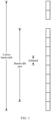
- the system frequency resource is also referred to as a carrier bandwidth (Carrier Bandwidth), and includes at least one bandwidth resource.
- the bandwidth resource is also referred to as a bandwidth part (BWP).
- the bandwidth resource and the bandwidth part have a same meaning and can be interchanged.
- the bandwidth part may be some consecutive or inconsecutive resources in the system frequency resource, or may be all resources in the system frequency resource.
- Each bandwidth part includes at least one consecutive subband or frequency domain resource block, and each subband or frequency domain resource block further includes a plurality of consecutive subcarriers.
- Each bandwidth part may correspond to a group of parameters (numerology), including but not limited to, for example, a subcarrier spacing (Subcarrier spacing) and a cyclic prefix (CP).
- Different bandwidth parts may correspond to different numerologies.
- TTI transmission time interval
- a plurality of bandwidth parts only one bandwidth part may be available and other bandwidth parts are unavailable.
- the bandwidth part is available means that a communication process mainly occurs in the bandwidth part.
- a plurality of bandwidth parts may be available, and other bandwidth parts are unavailable.
- In the unavailable bandwidth part usually, neither data sending nor data receiving is performed, but a measurement process of radio resource management may be performed.
- the BWPs may further be classified into a downlink BWP and an uplink BWP.
- the downlink BWP is used in a downlink communication process, and is mainly used to transmit a downlink signal and a downlink channel.
- the uplink BWP is used in an uplink communication process, and is mainly used to transmit an uplink signal and an uplink channel.
- a scheduling manner in which the network device schedules a bandwidth resource for the terminal based on frequency domain selectivity is a common scheduling manner.
- the network device may select a BWP having a relatively good channel condition to communicate with the terminal. Therefore, in addition to a current active BWP, there may further be a BWP having a better channel condition. In this case, the network device expects to flexibly switch the current active BWP of the terminal.
- US2016014778A1 describes a bandwidth allocation method that includes receiving, by user equipment, virtual bandwidth configuration information, where the virtual bandwidth configuration information is used for indicating a configuration of a virtual bandwidth; and performing, by the user equipment, signal reception and/or signal processing according to the virtual bandwidth indicated by the virtual bandwidth configuration information, where each virtual bandwidth is a part or all of a downlink maximum available bandwidth or a downlink transmission bandwidth, and the downlink maximum available bandwidth is a maximum bandwidth available for downlink transmission.
- WO2016029690A1 describes an information processing method in which a first base station acquires channel state information of N user equipments, and transmits same downlink control information to the user equipments classified with the channel state information.
- Bandwidth resource indication information is sent to a terminal, to guide the terminal to determine a BWP based on the bandwidth resource indication information.
- a network device sends bandwidth resource indication information to a terminal, to guide the terminal to determine a BWP based on the bandwidth resource indication information.
- a bandwidth resource receiving method a terminal, a bandwidth resource transmitting method, and a network device, as set forth in the claims.
- the terminal when the BWP indicated by the bandwidth resource indication information of the network device is different from the current active BWP, the terminal correctly interprets the indicated BWP based on the uplink transmission mode configuration status or the sounding reference signal configuration status in the indicated BWP, to determine whether to set the indicated BWP as the currently active bandwidth resource, so as to correctly perform uplink transmission.
- Implementation of the embodiments of the present invention can improve robustness and uplink transmission quality of a system.
- a system frequency resource is divided into at least one bandwidth resource, namely, a BWP.
- a network device may select a BWP having a relatively good channel condition for scheduling to a terminal, to communicate with the terminal. If there is a BWP having a better channel condition, the network device expects to switch the BWP for the terminal more flexibly.
- the network device configures a BWP for the terminal by using radio resource control (RRC) signaling. Specifically, the network device may configure an initial BWP or a first active (first active) BWP for the terminal by using RRC signaling. Further, when the network device expects to switch the BWP for the terminal, there are the following two manners:
- the network device configures a new BWP for the terminal by using system signaling, for example, RRC signaling, and the terminal uses the new BWP as a currently active BWP, to switch the BWP.
- the network device may configure the BWP by using the RRC signaling in an RRC signaling reconfiguration process.
- the network device dynamically notifies, by using downlink control signaling, for example, downlink control information (DCI) carried on a physical downlink control channel (PDCCH), the terminal to switch the BWP.
- DCI downlink control information
- PDCCH physical downlink control channel
- configuration information of an uplink transmission mode or an SRS in a current active BWP may be inconsistent with configuration information of an uplink transmission mode or an SRS in a BWP to which the terminal is to switch and that is indicated in the DCI. Therefore, the terminal cannot determine how to parse the configuration information of the corresponding uplink transmission mode or SRS in the current DCI, and consequently cannot smoothly switch the BWP, and cannot perform uplink transmission.
- Embodiments of the present invention provide a technical solution, so that when a bandwidth resource indicated by bandwidth resource indication information sent by a network device to a terminal is different from a current active bandwidth resource, the terminal can correctly parse downlink control information, to smoothly switch a BWP to perform uplink transmission.
- the network device may impose some constraints on uplink transmission mode-related configuration information or SRS-related configuration information on the indicated bandwidth resource, and other indication information carried in the downlink control information, to avoid contradiction or ambiguity, so that the terminal can correctly parse the bandwidth resource indication information.
- the terminal parses the downlink control information in an unambiguous parsing manner. In this way, the BWP is smoothly switched, and uplink transmission is performed.
- bandwidth part a bandwidth part in an NR technical standard that is currently in a discussion phase.
- the bandwidth part may include a group of consecutive physical resource blocks (PRB) in frequency domain, and a bandwidth of the bandwidth part is less than or equal to a maximum bandwidth supported by user equipment (UE).
- PRB physical resource blocks
- UE user equipment
- the bandwidth part may include the following attributes, for example, a system configuration parameter, a user equipment-related configuration parameter, a frequency position, and a bandwidth.
- the bandwidth resource may also be referred to as a frequency resource part, a partial frequency resource, a carrier bandwidth part, or another name. This is not limited in this application.
- the bandwidth resource may also be referred to as a subband, a narrowband, or another name.
- a specific form of the bandwidth resource is not limited in the embodiments of the present invention.
- bandwidth resource A and a bandwidth resource B as an example, that the bandwidth resource A and the bandwidth resource B are different includes: a part of or all of frequency resources included in the bandwidth resource A are not included in the bandwidth resource B, or a part of or all of frequency resources included in the bandwidth resource B are not included in the bandwidth resource A.
- bandwidth resource A and the bandwidth resource B are different may be:
- the frequency domain resources of the bandwidth resource A and the bandwidth resource B may completely overlap, partially overlap, or not overlap.
- Bandwidth resources may further be classified into an uplink BWP and a downlink BWP.
- the downlink BWP is used for downlink communication transmission, and is used to transmit a downlink channel, a downlink signal, and the like.
- the uplink BWP is used for uplink communication transmission, and is used to transmit an uplink channel, an uplink signal, and the like.
- One or more BWPs may be configured for a terminal in one serving cell or carrier. For example, one terminal in one serving cell or carrier supports a maximum of four BWPs. Specifically, one terminal in one serving cell or carrier may support a maximum of four uplink BWPs and/or four downlink BWPs.
- an active bandwidth resource is a BWP in an active state.
- the active state is relative to a time unit.
- active BWPs may be classified into three types: Initial active BWP (active BWP):
- the initial active BWP is usually a BWP that is in an active state and that is used for transmission in an initial access phase.
- the initial active BWP may be obtained by using a system message or a broadcast message, and a configuration of the initial active BWP is obtained by using higher layer signaling.
- First active BWP A corresponding first uplink active BWP and a corresponding first downlink active BWP may be obtained by configuring a BWP in an RRC message.
- a network device may specify one BWP or some BWPs as a first active BWP or first active BWPs.
- a terminal sets the BWP or the BWPs as the active BWP or the active BWPs, until the terminal receives bandwidth resource indication information, indicating the terminal to switch the current BWP.
- the current active bandwidth resource is a BWP in an active state in a current time unit, and is also a BWP that is currently active before a next effective BWP.
- An effective BWP can be used for uplink and downlink transmission.
- a currently active BWP namely, a BWP that is effective in a current time unit, may be a BWP that replaces an effective BWP in a previous time unit, or may be a BWP that has taken effect in a previous time unit and continues to take effect in the current time unit.
- the effective BWP is in an active state.
- Uplink transmission may be indicated by using the uplink grant DCI.
- CB codebook based
- NCB non-codebook based
- the DCI format 0_0 indicates a PUSCH transmitted through a single antenna, whether the PUSCH transmission indicated by the DCI format 0_0 is codebook based PUSCH transmission or non-codebook based PUSCH transmission may not be distinguished.
- the DCI format 0_1 may be used to indicate information related to a PUSCH transmitted based on a codebook or transmitted based on a non-codebook.
- Whether the PUSCH is transmitted based on a codebook or transmitted based on a non-codebook may be configured by using an RRC message.
- the RRC message may be configured for each BWP. That is, uplink transmission modes in different BWPs may be different, or there may be a case in which no uplink transmission mode is configured in one or more BWPs. In this way, in a BWP in which no uplink transmission mode is configured, uplink data can be scheduled only by using the DCI format 0_0 based on the foregoing descriptions.
- the DCI includes a plurality of pieces of indication information, for example, sounding reference signal indication information or sounding reference signal request information.
- the sounding reference signal indication information is used to indicate an SRS indicator ( SRI), and is represented as an SRI field.
- the sounding reference signal request information is used to indicate an SRS request (request), and is represented as an SRS request field.
- CB codebook
- NCB non-codebook
- a state corresponding to a value of the SRS request field may indicate a terminal not to send an SRS or to send an SRS, and the SRS is a preconfigured SRS that has a correspondence with the SRS request field in the DCI.
- Uplink transmission mode configuration information and SRS configuration information in each BWP are independently configured. Therefore, when configuration information in a current BWP is inconsistent with configuration information in a BWP to which a terminal is to switch and that is indicated in DCI, the terminal cannot determine how to interpret an SRI field or an SRS request field corresponding to the current DCI, and cannot determine a beam based on which a transmit beam for a PUSCH needs to be determined.
- the technical solutions of the embodiments of the present invention are intended to resolve the technical problem.
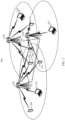
- FIG. 2 is an example of a schematic diagram of a wireless communications network 200 according to an embodiment of the present invention.
- the wireless communications network 200 includes base stations 202 to 206 and terminal devices 208 to 222.
- the base stations 202 to 206 may communicate with each other through backhaul (backhaul) links (as indicated by straight lines between the base stations 202 to 206).
- the backhaul link may be a wired backhaul link (for example, an optical fiber or a copper cable), or may be a wireless backhaul link (for example, microwave).
- the terminal devices 208 to 222 may communicate with the corresponding base stations 202 to 206 through radio links (as indicated by broken lines between the base stations 202 to 206 and the terminal devices 208 to 222).
- the base stations 202 to 206 are configured to provide wireless access services for the terminal devices 208 to 222.
- each base station corresponds to a service coverage area (which may also be referred to as a cell, and is indicated by each oval area in FIG. 2 ).
- a terminal device entering the area may communicate with the base station by using a wireless signal, to receive the wireless access service provided by the base station.
- the service coverage areas of the base stations may overlap.
- a terminal device in an overlapping area may receive wireless signals from a plurality of base stations. Therefore, the base stations may coordinate with each other, to serve the terminal device.
- the plurality of base stations may serve the terminal device in the overlapping area by using a coordinated multipoint ( CoMP) technology.
- CoMP coordinated multipoint
- the terminal device 222 may receive wireless signals from the base station 202 and the base station 204, and the base station 202 and the base station 204 may coordinate with each other, to serve the terminal device 222.
- the terminal device 220 may receive wireless signals from the base stations 202, 204, and 206, and the base stations 202, 204, and 206 may coordinate with each other, to serve the terminal device 220.
- the base station may also be referred to as a NodeB (NodeB), an evolved NodeB (eNodeB), an access point (AP), or the like.
- NodeB NodeB
- eNodeB evolved NodeB
- AP access point
- the base stations may further be classified into a macro base station for providing a macro cell (Macro cell), a micro base station for providing a micro cell ( micro cell), a femto base station for providing a femto cell (Femto cell), and the like.
- a macro base station for providing a macro cell
- micro cell micro cell
- femto base station for providing a femto cell
- another name may also be used for a future base station.
- the terminal devices 208 to 222 may be various wireless communications devices having a wireless communication function, but are not limited to, for example, a mobile cellular phone, a cordless phone, a personal digital assistant (PDA), a smartphone, a notebook computer, a tablet computer, a wireless data card, a wireless modem (Modem), or a wearable device such as a smartwatch.
- PDA personal digital assistant
- a smartphone a notebook computer
- tablet computer a wireless data card
- Modem wireless modem
- wearable device such as a smartwatch.
- IoT internet of things
- this type of device has the wireless communication function because of being configured with the wireless communications unit. Therefore, this type of device is also a type of wireless communications device.
- the terminal devices 208 to 222 may also be referred to as mobile stations, mobile devices, mobile terminals, wireless terminals, handheld devices, clients, or the like.
- a plurality of antennas may be configured for each of the base stations 202 to 206 and the terminal devices 208 to 222, to support a MIMO (multiple-input multiple-output) technology.
- the base stations 202 to 206 and the terminal devices 208 to 222 may not only support a single-user MIMO (SU-MIMO) technology, but also support a multi-user MIMO (MU-MIMO) technology.
- the MU-MIMO may be implemented based on a space division multiple access (SDMA) technology.
- the base stations 202 to 206 and the terminal devices 208 to 222 may further flexibly support a single-input single-output ( single-input single-output, SISO) technology, a single-input multiple-output (SIMO) technology, and a multiple-input single-output (MISO) technology, to implement various types of diversity technologies (including but not limited to, for example, a transmit diversity technology and a receive diversity technology) and multiplexing technologies.
- the diversity technology may include but is not limited to, for example, the transmit diversity (TD) technology and the receive diversity (RD) technology, and the multiplexing technology may be a spatial multiplexing (Spatial Multiplexing) technology.
- the transmit diversity technology may include but is not limited to, for example, diversity manners such as a space time transmit diversity (STTD), a space-frequency transmit diversity (SFTD), a time switched transmit diversity (TSTD), a frequency switched transmit diversity (FSTD), an orthogonal transmit diversity (OTD), and a cyclic delay diversity (CDD), and diversity manners obtained after deriving, evolving, and combining the foregoing various types of diversity manners.
- STTD space time transmit diversity
- SFTD space-frequency transmit diversity
- TSTD time switched transmit diversity
- FSTD frequency switched transmit diversity
- OTD orthogonal transmit diversity
- CDD cyclic delay diversity
- transmit diversity manners such as space-time block coding (STBC), space frequency block coding (SFBC), and the CDD are used in an LTE (Long Term Evolution) standard.
- LTE Long Term Evolution
- the transmit diversity is described above in general by using examples. A person skilled in the art should understand that the transmit diversity is further implemented in a plurality of other manners in addition to those in the foregoing examples. Therefore, the foregoing descriptions should not be understood as limitations on the technical solutions of the present invention, and the technical solutions of the present invention should be understood as applicable to various possible transmit diversity solutions.
- the base stations 202 to 206 and the terminal devices 208 to 222 may communicate with each other by using various wireless communications technologies, including but not limited to, for example, a time division multiple access (s, TDMA) technology, a frequency division multiple access (FDMA) technology, a code division multiple access (CDMA) technology, a time division-synchronous code division multiple access (TD-SCDMA) technology, an orthogonal frequency division multiple access (OFDMA) technology, a single carrier frequency division multiple access (, SC-FDMA) technology, a space division multiple access (SDMA) technology, and evolved and derived technologies of these technologies.
- a time division multiple access s, TDMA
- FDMA frequency division multiple access
- CDMA code division multiple access
- TD-SCDMA time division-synchronous code division multiple access
- OFDMA orthogonal frequency division multiple access
- SC-FDMA single carrier frequency division multiple access
- SDMA space division multiple access
- RAT radio access technologies
- GSM global system for mobile communications
- WCDMA wideband CDMA
- Wi-Fi defined in 802.22 series standards
- WiMAX worldwide interoperability for microwave access
- LTE long term evolution
- LTE-A LTE-Advanced
- LTE-A LTE-Advanced
- the wireless communications network 200 shown in FIG. 2 is merely used as an example, and is not intended to limit the technical solutions of the present invention.
- the wireless communications network 200 may further include another device, and a quantity of base stations and a quantity of terminal devices may further be configured based on a specific requirement.
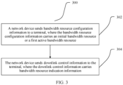
- FIG. 3 is an example of a flowchart of a method 300 for indicating bandwidth resource switching according to an embodiment of the present invention.
- the method 300 may be performed by a network device, and the network device may be but is not limited to, for example, the base stations 202 to 206 shown in FIG. 2 .
- Step 302 The network device sends bandwidth resource configuration information to a terminal, where the bandwidth resource configuration information carries an initial bandwidth resource or a first active bandwidth resource.
- the bandwidth resource configuration information carries an initial bandwidth resource or a first active bandwidth resource.
- the bandwidth resource configuration information is sent to the terminal by using higher layer configuration signaling such as RRC signaling.
- the RRC signaling may carry indication information of the initial BWP or the first active BWP (first active BWP), to configure an available BWP for the terminal.
- the network device may configure a maximum of 4N uplink (UL) BWPs and/or 4N downlink (DL) BWPs for the terminal by using the RRC signaling, where N is a non-zero positive integer.
- a value of N may be 1, 2, 3, or 4.
- the RRC signaling is layer 3 (Layer 3) signaling, and the layer 3 signaling is usually some control messages.
- a sending periodicity or a control periodicity of the L3 signaling is usually relatively long, and the L3 signaling is applicable to sending of some information that does not change frequently.
- the L3 signaling is usually used to carry some configuration information.
- the bandwidth resource configuration information may alternatively be sent by using layer 3 signaling other than the RRC signaling.
- the network device obtains bandwidth resource indication information carried in downlink control signaling sent by another network device to the terminal; or after the network device sends downlink control signaling to the terminal, the network device notifies another network device of bandwidth resource indication information carried in the downlink control signaling sent by the network device to the terminal.
- a bandwidth resource indicated by the bandwidth resource indication information sent by the network device is the same as a bandwidth resource indicated by the bandwidth resource indication information carried in the downlink control signaling sent by the another network device to the terminal.
- the network device may alternatively send the downlink control signaling without negotiating with the another network device.
- the terminal device switches, based on the identifier of the bandwidth resource, the bandwidth resource to the bandwidth resource indicated by the network device, feeds back an acknowledgement to the network device, and feeds back a negative acknowledgement to the another network device; or the terminal feeds back, to the another network device, the identifier of the bandwidth resource to which the terminal needs to switch, is to switch, or has switched.
- the network device may receive a negative acknowledgement fed back by the terminal, or further receive an identifier of a bandwidth resource that is fed back by the terminal and to which the terminal needs to switch, is to switch, or has switched.
- the network device may alternatively receive, from the another network device, an identifier of a bandwidth resource to which the terminal needs to switch, is to switch, or has switched.
- the downlink control signaling in this specification may be downlink control information.
- the network device may dynamically notify, by using the downlink control information, the terminal to switch the BWP.
- an uplink transmission mode and an SRS need to be configured in a current active BWP. Otherwise, based on the foregoing descriptions, the network device cannot indicate, by using DCI format 0_1, the terminal to switch the BWP.
- the network device When the network device sends the bandwidth resource indication information to the terminal by using the downlink control information, an uplink transmission mode and an SRS need to be configured in the BWP indicated by the bandwidth resource indication information. Otherwise, the network device can schedule the terminal only by using DCI format 0_0, and if the network device indicates the terminal to switch the BWP in this case, after the terminal switches the BWP, the network device cannot schedule the terminal again by using the downlink control information. Consequently, system performance flexibility is affected.
- the network device further needs to include transmission indication information in the downlink control information, to indicate single-antenna transmission.
- the network device can schedule the terminal only by using DCI format 0_0.
- the transmission indication information is antenna port indication information, and the antenna port indication information indicates one antenna port; or the transmission indication information is precoding indication information, the precoding indication information includes a transmission rank indication or a precoding matrix, and a value of a rank of the transmission rank indication is 1, or the precoding matrix is a 1 ⁇ 1 dimensional matrix, and content of the matrix is [1].
- the transmission indication information of the network device is set, so that the terminal performs transmission on a single antenna port.
- the network device receives the uplink shared channel on a single antenna port.
- the DCI further carries SRI request information, and the SRI request information indicates the terminal not to send a sounding resource, because in this case, the terminal has no SRS resource configuration in the indicated BWP.
- SRS request information is specifically represented as an SRS request field
- a state corresponding to a value of the SRS request field may indicate the terminal not to send an SRS or to send an SRS
- the SRS is a preconfigured SRS that has a correspondence with the SRS request field in the DCI.
- the value of the SRS request field can only correspond to a state in which no SRS is to be sent.
- the SRS request field may be X bits, and one value of the field is a state.
- a first state indicates the terminal not to send an SRS
- a second state indicates the terminal to send a first SRS
- a third state indicates the terminal to send a second SRS
- a fourth state indicates the terminal to send a third SRS.
- the value should correspond to the first state.
- the SRS request field is two bits, 00 indicates that no SRS is to be sent, 01 indicates that the first SRS is to be sent, 10 indicates that the second SRS is to be sent, and 11 indicates that the third SRS is to be sent.
- the value of the SRS request field should be 00.
- bit information indicating the terminal not to send the sounding resource may alternatively be in another form.
- the network device may schedule the terminal by using DCI format 0_1.
- the network device when the bandwidth resource indication information is sent to the terminal by using the downlink control information, the network device may impose some constraints on uplink transmission mode-related configuration information and SRS-related configuration information on the indicated bandwidth resource, and other indication information carried in the downlink control information. In this way, no ambiguity occurs when the terminal parses the downlink control information, so that the terminal determines whether to switch the BWP, to correctly perform uplink transmission.
- the foregoing provides operation descriptions when the network device indicates, by using the downlink control information, the terminal to switch the BWP.
- the following is related to a claimed embodiment.
- the following describes how the terminal parses, when receiving, from the network device, the downlink control information and the bandwidth resource indication information carried in the downlink control information, the downlink control information and the bandwidth resource indication information carried in the downlink control information, and how to switch the BWP.
- FIG. 4 is an example of a flowchart of a bandwidth resource switching method 400 according to an embodiment of the present invention.
- the method 400 may be performed by a receive end device, and the receive end device may be but is not limited to, for example, the terminal devices 208 to 222 shown in FIG. 2 .
- Step 402 A terminal receives downlink control information, where the downlink control information carries bandwidth resource indication information.
- the terminal has obtained bandwidth resource configuration information by performing a series of operations such as uplink synchronization and downlink synchronization in step 401.
- a network device sends the bandwidth resource configuration information to the terminal device by using a system message or a broadcast message, and the terminal device selects a corresponding BWP as a currently active BWP based on an initial BWP or a first active BWP (first active BWP) configured in the bandwidth resource configuration information, and performs uplink transmission in the BWP.
- An uplink synchronization process and a downlink synchronization process are well known to a person skilled in the art, and details are not described herein again.
- the network device may specify one BWP or some BWPs as a first active BWP or first active BWPs.
- the terminal when receiving an indication message, sets the BWP or the BWPs as an active BWP or active BWPs, and the active BWP is a currently active BWP until the terminal receives the bandwidth resource indication information indicating the terminal to switch the current BWP.
- the current active BWP is a BWP that takes effect in a current time unit.
- the terminal may send and receive a signal.
- the terminal does not send or receive a signal.
- the terminal may be allowed to perform radio resource management measurement outside a resource range of the current active BWP.
- Switching of an active BWP in a time unit may be notified by using DCI in a communication process.
- a granularity of one time unit may be referred to as a unit of time.
- the unit of time is used to represent a time unit in time domain, and may be, for example, one or more of a sampling point, a symbol, a mini slot, a slot, a subframe, or a radio frame.
- Information about the unit of time may include a type, a length, a structure, or the like of the unit of time.
- the unit of time may be understood as a time domain unit for resource scheduling.
- the terminal device may receive more than one piece of downlink control signaling in the current time unit, and the downlink control signaling may be used for an uplink grant or a downlink grant. If the terminal receives a plurality of pieces of uplink bandwidth resource indication information in the current time unit; or the terminal receives a plurality of pieces of downlink bandwidth resource indication information in the current time unit; or the terminal receives a plurality of pieces of uplink bandwidth resource indication information and time units indicated by uplink control signaling in which the uplink bandwidth resource indication information of the terminal is located are consistent; or the terminal receives a plurality of pieces of downlink bandwidth resource indication information and time units indicated by downlink control signaling in which the downlink bandwidth resource indication information of the terminal is located are consistent, the terminal device does not expect that bandwidth resources indicated by the plurality of pieces of bandwidth resource indication information received are different, or if the plurality of pieces of bandwidth resource indication information are different, the terminal device uses one of the plurality of pieces of bandwidth resource indication information.
- Step 404 The terminal determines an indicated bandwidth resource based on the bandwidth resource indication information.
- the terminal device may receive more than one piece of downlink control signaling, and the terminal device does not expect that bandwidth resources indicated by a plurality of pieces of bandwidth resource indication information received by the terminal device are different.
- the bandwidth resources indicated by the plurality of pieces of bandwidth resource indication information received by the terminal device should be the same, that is, the bandwidth resources indicated by the plurality of pieces of bandwidth resource indication information sent by a plurality of network devices to the terminal device are the same.
- bandwidth resources indicated by the plurality of pieces of bandwidth resource indication information sent by the plurality of network devices are the same may mean that the network devices in a plurality of intra-frequency cells or the network devices in a same cell send the plurality of pieces of bandwidth resource indication information, and the bandwidth resources indicated by the plurality of pieces of bandwidth resource indication information are the same; or the plurality of pieces of bandwidth resource indication information sent by the plurality of network devices in different cells or in inter-frequency cells after negotiation indicate frequency domain resources at a same bandwidth position.
- a process in which the plurality of network devices send, to the terminal through negotiation, the bandwidth resource indication information indicating the frequency domain resources at the same bandwidth position is specifically:
- the network devices exchange information, where the exchanged information includes the bandwidth resource indication information (for example, BWP indication information), and the network device further sends, to another network device, a time at which the bandwidth resource indication information is to be sent to the terminal.
- the network devices negotiate with each other to send DCI in a time unit, for example, a slot (slot) n, to indicate a same bandwidth resource, for example, a BWP (y).
- the network device sends the DCI based on the exchanged information, where the DCI carries the bandwidth resource indication information or further includes the time at which the bandwidth resource indication information is to be sent.
- the frequency domain resource herein is a resource block (RB), a resource block group (RBG), a predefined subband (subband), a band (band), a bandwidth part (BWP), a component carrier (CC), or a cell (cell).
- the cell herein may be a serving cell ( serving cell).
- the downlink control signaling may be DCI carried on a PDCCH.
- a plurality of pieces of downlink control signaling may be sent by using a same frequency domain resource or different frequency domain resources.
- Whether a plurality of pieces of downlink control signaling are sent by using a same frequency domain resource may be determined by determining whether the plurality of pieces of downlink control signaling are from a same cell, that is, determining whether PDCCH configurations corresponding to the plurality of pieces of downlink control signaling are configured in a same cell configuration (cell configuration); or whether PDSCH configurations respectively scheduled by using the plurality of pieces of downlink control signaling are configured in a same cell configuration (cell configuration).
- the plurality of pieces of downlink control signaling are sent by using the same frequency domain resource, that is, the plurality of pieces of downlink control signaling are from the same cell, identifiers of bandwidth resources indicated by a plurality of pieces of bandwidth resource indication information indicated by the plurality of pieces of downlink control signaling are the same, that is, bandwidth positions corresponding to the bandwidth resources are the same.
- identifiers of bandwidth resources indicated by a plurality of pieces of bandwidth resource indication information indicated by the plurality of pieces of downlink control signaling may be different, but bandwidth positions corresponding to the bandwidth resources indicated by the plurality of pieces of bandwidth resource indication information are the same. That bandwidth positions are the same includes: any two of start positions, bandwidth sizes, and end positions of the bandwidth resources indicated by the plurality of pieces of bandwidth resource indication information are the same.
- the bandwidth resource may be obtained by obtaining the end position based on the start position and the bandwidth size; or the bandwidth resource may be obtained based on the start position and the end position; or the bandwidth resource may be obtained by obtaining the start position based on the bandwidth size and the end position.
- That start positions of the bandwidth resources are the same includes that actual start positions determined based on frequency domain reference points and offsets are the same.
- An example in which the bandwidth resource is a BWP is used.
- a start position of the BWP is relative to a frequency domain reference point (for example, a reference point point A) in a serving cell, and the start position of the BWP may be notified by the network device to the terminal.
- start positions are the same may mean that actual start positions of the bandwidth resources determined based on frequency domain reference points and offsets are the same.
- a sum of a difference between frequency domain reference points of the different serving cells and a difference between offsets of the bandwidth resources indicated by the plurality of pieces of bandwidth resource indication information of the different serving cells relative to the frequency domain reference points is equal to 0, to ensure that actual start positions of different bandwidth resources are the same.
- a row in Table 1 represents frequency domain units in ascending order.
- the actual start position of the BWP in the first serving cell is the same as the actual start position of the BWP in the second serving cell.
- the start position or the end position of the BWP described herein is a start position or an end position obtained after a numerology (numerology) of the serving cell is considered.
- the start position or the end position of the BWP is a start position or an end position that is converted by using the numerology as a reference.
- the numerology may be used to determine a subcarrier spacing, a symbol length, a CP length (a cyclic prefix), and the like.
- a numerology of the first serving cell is marked as u1
- a numerology of the second serving cell is marked as u2
- offset 1*(2 ⁇ u1) offset 2*(2 ⁇ u2).
- a granularity of a minimum frequency domain unit of the first serving cell is half of a granularity of a minimum frequency domain unit of the second serving cell.
- a value of the offset 1 of the first cell is twice a value of the offset 2, where k indicates 1000.
- numerologies corresponding to the plurality of indicated bandwidth resources are the same, that is, the numerologies corresponding to the bandwidth resources indicated by the different network devices are the same.
- the terminal may determine the indicated bandwidth resource based on any one or more of the plurality of pieces of bandwidth resource indication information, that is, select a bandwidth resource corresponding to one piece of bandwidth resource indication information as the indicated bandwidth resource. Then, a corresponding acknowledgement is fed back for the downlink control signaling selected by the terminal, and a negative acknowledgement is fed back for other downlink control signaling. Further, the terminal may further feed back, for the other downlink control signaling, an identifier of the bandwidth resource selected by the terminal, to notify a corresponding network device of the bandwidth resource to which the terminal is to switch.
- At least two of the bandwidth resources indicated by the bandwidth resource indication information carried in the plurality of pieces of downlink control signaling are different.
- the network devices exchange bandwidth resource configuration information configured by the network devices for the terminal, for example, BWP configuration information, which is specifically information such as a start position, an end position, and a size of a BWP.
- BWP configuration information which is specifically information such as a start position, an end position, and a size of a BWP.
- the network devices may determine actual available bandwidth resources based on bandwidth resource information that is to be indicated by the network devices, and then the network devices respectively indicate the actual available bandwidth resources to the terminal.
- one implementation is determining, by the terminal, an intersection set of the bandwidth resources indicated by the plurality of pieces of bandwidth resource indication information as the indicated bandwidth resource.
- the terminal uses, as a start position of the indicated bandwidth resource, a start position having a largest identifier value in the start positions corresponding to the bandwidth resources indicated by the plurality of pieces of bandwidth resource indication information; and/or the terminal uses, as an end position of the indicated bandwidth resource, an end position having a smallest identifier value in the end positions corresponding to the bandwidth resources indicated by the plurality of pieces of bandwidth resource indication information.
- the determined indicated bandwidth resource is a BWP.
- the terminal uses, as a start position of the BWP, a start position having a second largest or largest value of an identifier or an index (index) in actual start positions corresponding to the bandwidth resources indicated by the plurality of pieces of bandwidth resource indication information; and uses, as an end position of the BWP, an end position having a second smallest or smallest value of an identifier or an index (index) in actual end positions corresponding to the bandwidth resources indicated by the plurality of pieces of bandwidth resource indication information.
- the indicated bandwidth resource determined by the terminal is a BWP including frequency domain units starting from the start position K4 to the end position K5.
- the network device receives feedback information of the terminal after indicating the bandwidth resource indication information (for example, indicating an ID of the BWP) to the terminal.
- a time at which the network device receives the feedback may be preset duration. In the preset duration, if the terminal feeds back a NACK, the network device considers that the bandwidth resource indicated by the network device is not used by the terminal as a bandwidth resource to which the terminal is to switch. In other words, the network device considers that the terminal is not to switch to the bandwidth resource indicated by the network device. Otherwise, the network device considers that the terminal is to switch to the bandwidth resource indicated by the network device.
- a plurality of network devices when a plurality of network devices send a plurality of pieces of bandwidth resource indication information to the terminal by using downlink control signaling, if the plurality of pieces of bandwidth resource indication information are different, the terminal device uses one of the plurality of pieces of bandwidth resource indication information.
- the terminal device determines, based on bandwidth resource indication information carried in downlink control signaling corresponding to a preset identifier, the indicated bandwidth resource.
- the preset identifier is a specified identifier of a control resource set, a smallest identifier of a control resource set, a largest identifier of a control resource set, an identifier of a control resource set group, a smallest identifier of a control resource set group, a largest identifier of a control resource set group, an identifier of search space, a smallest identifier of search space, or a smallest identifier of a search space group corresponding to the downlink control signaling.
- the terminal device uses downlink control signaling corresponding to a smallest identifier or a largest identifier in identifiers of DCI corresponding to the downlink control signaling. For DCI that is different from a BWP switching indication complied with by the terminal device, the terminal device feeds back a negative acknowledgement (NACK) for the DCI.
- NACK negative acknowledgement
- the identifier of the DCI may be an identifier of a CORESET or a CORESET group in which the DCI is located, an identifier of a search space group, or an identifier of search space.
- the terminal selects a bandwidth resource that corresponds to a smallest bandwidth position in the bandwidth positions indicated by the plurality of pieces of bandwidth resource indication information, and determines the selected bandwidth resource as the indicated bandwidth resource.
- bandwidth resources respectively indicated by bandwidth resource indication information carried in three pieces of downlink control signaling from the first serving cell, the second serving cell, and the third serving cell are the BWP 1, the BWP 2, and the BWP 3, and a bandwidth position of the BWP 3 of the third serving cell is the smallest in bandwidth positions of the BWP 1, the BWP 2, and the BWP 3. Therefore, the terminal uses the BWP 3 as the indicated bandwidth resource.
- the terminal After selecting bandwidth resource indication information carried in one piece of downlink control signaling, and determining an indicated bandwidth resource, the terminal feeds back an acknowledgement (ACK) to a network device corresponding to the selected downlink control signaling.
- ACK acknowledgement
- a bandwidth resource switching time may be defined.
- the bandwidth resource switching time means that after receiving the downlink control signaling, the terminal starts switching after a predetermined time, a start position of the bandwidth resource needs to ensure that the terminal has completed feedback to another network device and completes the switching in another predetermined time, and an end position of the bandwidth resource needs to ensure that the network device knows that the terminal device has switched to the new bandwidth resource.
- the terminal may further feed back, for the other downlink control signaling, an identifier of the bandwidth resource, for example, an identifier of a BWP, to which the terminal device needs to switch or is to switch.
- an identifier of the bandwidth resource for example, an identifier of a BWP, to which the terminal device needs to switch or is to switch.
- the terminal device receives DCI 1 that indicates the BWP 1, the terminal device receives DCI 2 that indicates the BWP 2, and the DCI 1 and the DCI 2 are sent in a same time unit. If the terminal device determines, according to a preset rule, to switch to the BWP 1, the terminal device feeds back a NACK for scheduling of the DCI that is not complied with. The terminal device may further feed back, by using a feedback resource (a PUCCH/PUSCH) corresponding to the DCI 2, to a network device, for example, a TRP 2, corresponding to the DCI 2, so that the TRP 2 corresponding to the DCI 2 can receive feedback information.
- the feedback information includes information about the BWP 1 to which the terminal device is to switch.
- the TRP 2 learns that the BWP 2 indicated by the DCI 2 sent by the TRP 2 is not selected, and the TRP 2 may further learn that the terminal device is to switch to the BWP 1, or that the terminal device is to switch to the BWP 1 is indicated to the TRP 2.
- the network device Regardless of whether the terminal uses the same bandwidth resource sent through negotiation between the foregoing network devices, or the terminal uses only the bandwidth resource indicated by one of the plurality of pieces of bandwidth resource indication information, the network device finally needs to learn of a bandwidth resource that can be actually supported or used by the terminal.
- the bandwidth resource that can be actually supported or used by the terminal is defined as an actual bandwidth resource.
- the terminal does not expect to receive a downlink signal (for example, a PDSCH, a PDCCH, or a CSI-RS) outside a frequency domain resource corresponding to the actual bandwidth resource.
- a downlink signal for example, a PDSCH, a PDCCH, or a CSI-RS
- the network device may schedule a signal within an actual bandwidth resource range supported by the terminal or beyond the actual bandwidth resource range.
- the network device should know that when receiving a signal, the terminal can receive only a signal within the actual bandwidth resource range supported by the terminal, but cannot receive a signal beyond the actual bandwidth resource range.
- the terminal cannot transmit an uplink signal (for example, a PUSCH, a PUCCH, or an SRS) beyond the actual bandwidth resource range supported by the terminal. Therefore, when the network device schedules an uplink signal, a frequency domain resource of the scheduled uplink signal falls within the actual bandwidth resource range supported by the terminal, that is, does not beyond the actual bandwidth resource range.
- an uplink signal for example, a PUSCH, a PUCCH, or an SRS
- the terminal does not switch the BWP.
- the terminal continues to perform uplink transmission based on an uplink transmission mode configuration in the current active BWP, and sends an SRS based on SRS configuration information.
- Step 406 When the indicated bandwidth resource is different from a current active bandwidth resource, determine a currently active bandwidth resource based on an uplink transmission mode configuration status or a sounding reference signal configuration status on the indicated bandwidth resource.
- the uplink transmission mode configuration status or the sounding reference signal configuration status on the indicated bandwidth resource is whether an uplink transmission mode or an SRS is configured on the indicated bandwidth resource, a quantity of uplink transmission modes or configured SRSs or a quantity of groups of uplink transmission modes or configured SRSs, or the like.
- an uplink transmission mode for example, a PUSCH transmission mode
- an SRS is independently configured in each BWP. Therefore, when receiving the bandwidth resource indication information of the network device, the terminal first needs to interpret the bandwidth resource indication information, determines, based on the uplink transmission mode configuration status or the sounding reference signal configuration status on the indicated bandwidth resource, whether the BWP indicated by the network device is set to the currently active BWP.
- no uplink transmission mode is configured, for example, no PUSCH transmission mode or SRS is configured, in the indicated BWP, because if no PUSCH transmission mode or SRS is configured in the BWP, the network device is allowed to schedule the terminal only by using the DCI format 0_0.
- the network device when the network device indicates BWP switching by using the DCI, there are the following three configuration statuses of the uplink transmission mode or the sounding reference signal on the indicated bandwidth resource:
- no uplink transmission mode or sounding reference signal is configured on the indicated bandwidth resource.
- the first case specifically includes: no uplink transmission mode is configured; no SRS is configured; or the uplink transmission mode is configured, but no SRS is configured.
- an uplink transmission mode is configured on the indicated bandwidth resource, and one sounding reference signal is configured or one group of sounding reference signals are configured.
- an uplink transmission mode is configured on the indicated bandwidth resource, and at least two or at least two groups of sounding reference signals are configured.
- this embodiment of the present invention provides different operation manners, so that the terminal can correctly parse the bandwidth resource indication information, to perform uplink transmission or SRS sending.
- the terminal may have the following several processing manners:
- the downlink control information further carries sounding reference signal request information, and the terminal ignores the sounding reference signal request information.
- the terminal may consider that the sounding reference signal request information has not been received; or
- the downlink control information further carries sounding reference signal indication information, and the terminal ignores the sounding reference signal indication information.
- the terminal may consider that the sounding reference signal indication information has not been received; or may set the sounding reference signal indication information to be invalid, where a manner of setting the sounding reference signal indication information to be invalid may be setting each bit of an SRI field indicating the sounding reference signal indication information to zero or null, or another value indicating that the sounding reference signal indication information is invalid; or
- the terminal When there is neither PUSCH configuration nor SRS configuration on the bandwidth resource indicated by the bandwidth resource indication information carried in the DCI sent by the network device to the terminal, regardless of a quantity of SRS resources or a specific SRS resource indicated by the SRI field in the DCI, the terminal ignores the SRS resource, or sets a quantity of bits of the SRI field carried in the DCI to 0, because in this case, no SRS resource is configured in the BWP indicated by the DCI.
- the terminal does not expect to receive transmission indication information that is sent by the network device and that indicates non-single-antenna transmission, or the terminal considers that single-antenna transmission is performed in the indicated BWP. Specifically, the terminal does not expect that antenna port indication information carried in the DCI sent by the network device to the terminal indicates more than one antenna port. In other words, regardless of whether the antenna port indication information indicates more than one antenna port, the terminal considers that there is one antenna port.
- the terminal uses the antenna port indicated by the antenna port indication information as a first antenna port, there is one first antenna port, and the first antenna port may be an antenna port with a predefined value, for example, an antenna port with a least significant bit, an antenna port with a most significant bit, or an antenna port corresponding to an antenna port number configured by using higher layer signaling.
- the terminal does not expect that SRS request information sent by the network device to the terminal by using the downlink control information does not correspond to that no SRS is to be sent. In other words, the terminal expects that SRS request information sent by the network device to the terminal corresponds to that no SRS is to be sent. If the received SRS request information corresponds to that an SRS is to be sent, the terminal ignores the received SRS request information or considers each bit of an SRS request field indicating the SRS request information as 0.
- the SRS request field may be X bits, and one value of the field is a state. For example, a first state indicates the terminal not to send an SRS, a second state indicates the terminal to send a first SRS, a third state indicates the terminal to send a second SRS, and a fourth state indicates the terminal to send a third SRS. In this case, the value should correspond to the first state.
- the SRS request field is two bits, 00 indicates that no SRS is to be sent, 01 indicates that the first SRS is to be sent, 10 indicates that the second SRS is to be sent, and 11 indicates that the third SRS is to be sent.
- the value of the SRS request field should be 00.
- bit information indicating the terminal not to send the sounding resource may alternatively be in another form.
- the indicated BWP of the terminal has a PUSCH transmission mode configuration, but has only one SRS resource configuration.
- the terminal should perform transmission based on the configured one SRS resource. Therefore, regardless of a quantity of SRS resources and a specific SRS resource indicated by the SRI field, the terminal considers that each information bit of the SRI field is useless, so that the terminal ignores the SRI field in the DCI; or does not parse the SRI field; or even if the terminal parses the SRI field, the terminal performs no processing on content obtained through the parsing. Alternatively, the terminal considers that a quantity of bits of the SRI field in the DCI is 0 or null, or another value indicating that the SRI field is invalid.
- the terminal determines, based on the SRS resource configured in the indicated BWP, an SRS associated with a PUSCH to be transmitted.
- the terminal determines that beam information of an indicated SRS may be a downlink beam (for example, a beam of an SSB or a CSI-RS) or an uplink beam (for example, a beam of another SRS) from the indicated BWP configured in the SRS, or a beam from another BWP or carrier configured in the SRS.
- a downlink beam for example, a beam of an SSB or a CSI-RS
- an uplink beam for example, a beam of another SRS
- the indicated BWP of the terminal has a PUSCH transmission mode configuration, and has a plurality of SRS resource configurations.
- the terminal determines, based on the SRI field carried in the DCI, a beam for sending a PUSCH.
- the terminal interprets the SRI field in the DCI, if a quantity of bits required by the SRI field of the indicated BWP is greater than a quantity of bits of an SRI field in the current BWP, the terminal needs to perform a zero adding operation on the bit of the SRI field in the current DCI, until the quantity of bits of the SRI field is equal to the quantity of bits required by the SRI field of the indicated BWP.
- the terminal ignores a high-order bit of the SRI field in the DCI, and reads only a low-order bit of the quantity of bits required by the indicated BWP.
- the terminal determines, based on the SRS configured in the indicated BWP, an SRS associated with the PUSCH to be transmitted. For example, if two SRSs are configured in the indicated BWP, and the SRI field in the DCI indicates a second SRS, the terminal determines that the second SRS is the second SRS in the two SRSs configured in the indicated BWP.
- the terminal determines that beam information of the indicated SRS may be a downlink beam (for example, a beam of an SSB or a CSI-RS) or an uplink beam (for example, a beam of another SRS) from the indicated BWP configured in the SRS, or a beam from another BWP or carrier configured in the SRS.
- a downlink beam for example, a beam of an SSB or a CSI-RS
- an uplink beam for example, a beam of another SRS
- the terminal determines the PUSCH transmit beam and the SRS resource that are in the indicated BWP, sets the BWP indicated by the bandwidth resource indication information carried in the DCI as the currently active BWP, and sends the PUSCH on the currently active BWP.
- the terminal when receiving the bandwidth resource indication information sent by the network device by using the downlink control information, the terminal parses the downlink control information in an unambiguous parsing manner. In this way, the BWP is smoothly switched, and the uplink transmission is performed.
- the present invention further provides a network device and a terminal, which are respectively configured to perform the method 300 for indicating bandwidth resource switching shown in FIG. 3 and the bandwidth resource switching method 400 shown in FIG. 4 .
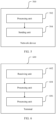
- FIG. 5 is a schematic diagram of a logical structure of a network device 500 according to an embodiment of the present invention.
- the network device 500 may be but is not limited to, for example, the base stations 202 to 206 shown in FIG. 2 .
- the network device 500 includes a processing unit 502 and a sending unit 504.
- the processing unit 502 is configured to configure bandwidth resource configuration information for a terminal, where the bandwidth resource configuration information carries an initial bandwidth resource or a first active bandwidth resource;
- the network device further includes a receiving unit (not shown in the figure), configured to obtain bandwidth resource indication information carried in downlink control signaling sent by another network device to a terminal; or the sending unit 504 of the network device is configured to notify another network device of bandwidth resource indication information carried in downlink control signaling sent by the network device to a terminal; and the sending unit 504 is further configured to send the downlink control signaling to the terminal, where the downlink control signaling carries the bandwidth resource indication information, and a bandwidth resource indicated by the bandwidth resource indication information is the same as a bandwidth resource indicated by the bandwidth resource indication information carried in the downlink control signaling sent by the another network device to the terminal.
- a receiving unit not shown in the figure
- bandwidth resources indicated by a plurality of pieces of bandwidth resource indication information sent by a plurality of network devices are the same may mean that the network devices in a plurality of intra-frequency cells or the network devices in a same cell send the plurality of pieces of bandwidth resource indication information, and the bandwidth resources indicated by the plurality of pieces of bandwidth resource indication information are the same; or the plurality of pieces of bandwidth resource indication information sent by the plurality of network devices in different cells or in inter-frequency cells after negotiation indicate frequency domain resources at a same bandwidth position.
- the network devices exchange information, where the exchanged information includes the bandwidth resource indication information (for example, BWP indication information), and the network device further sends, to another network device, a time at which the bandwidth resource indication information is to be sent to the terminal.
- the network devices negotiate with each other to send DCI in a time unit, for example, a slot (slot) n, to indicate a same bandwidth resource, for example, a BWP (y).
- the network device sends the DCI based on the exchanged information, where the DCI carries the bandwidth resource indication information or further includes the time at which the bandwidth resource indication information is to be sent.
- the sending unit 502 is configured to send downlink control signaling to a terminal, and the downlink control signaling carries bandwidth resource indication information.
- network devices exchange bandwidth resource configuration information configured by the network devices for the terminal, for example, BWP configuration information, which is specifically information such as a start position, an end position, and a size of a BWP.
- BWP configuration information which is specifically information such as a start position, an end position, and a size of a BWP.
- the network devices may determine actual available bandwidth resources based on bandwidth resource information that is to be indicated by the network devices, and then the network devices respectively indicate the actual available bandwidth resources to the terminal.
- the bandwidth resources respectively indicated by the plurality of network devices may not be completely the same; and the receiving unit is further configured to receive, from the terminal, an acknowledgement, a negative acknowledgement, or an identifier of a bandwidth resource to which the terminal is to switch.
- the network device 500 is configured to perform the method 300 for indicating bandwidth resource switching shown in FIG. 3 and the bandwidth resource sending method in the method 300. Related technical features have been described in detail above with reference to the method 300 shown in FIG. 3 . Therefore, details are not described herein again.
- FIG. 6 is a schematic diagram of a logical structure of a terminal 600 according to an embodiment of the present invention.
- the terminal 600 may be but is not limited to, for example, the terminals 208 to 222 shown in FIG. 2 .
- the terminal 600 includes a receiving unit 602 and a processing unit 604.
- the receiving unit 602 is configured to receive downlink control information, where the downlink control information carries bandwidth resource indication information;
- the receiving unit 602 is configured to receive a plurality of pieces of downlink control signaling, where the downlink control signaling carries bandwidth resource indication information, and bandwidth resources indicated by a plurality of pieces of bandwidth resource indication information are the same; and the processing unit 604 is configured to determine the indicated bandwidth resource based on the bandwidth resource indication information.
- the receiving unit 602 is configured to receive a plurality of pieces of downlink control signaling, where the downlink control signaling carries bandwidth resource indication information; and the processing unit 604 is configured to determine an indicated bandwidth resource based on the bandwidth resource indication information.
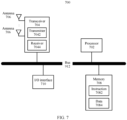
- FIG. 7 is a schematic diagram of a hardware structure of a network device 700 according to an embodiment of the present invention.
- the network device 700 includes a processor 702, a transceiver 704, a plurality of antennas 706, a memory 708, an I/O (input/output, Input/Output) interface 710, and a bus 712.
- the transceiver 704 further includes a transmitter 7042 and a receiver 7044, and the memory 708 is further configured to store an instruction 7082 and data 7084.
- the processor 702, the transceiver 704, the memory 708, and the I/O interface 710 are in communication connection with each other through the bus 712.
- the plurality of antennas 706 are connected to the transceiver 704.
- the processor 702 may be a general purpose processor but is not limited to, for example, a central processing unit (CPU), or may be a dedicated processor but is not limited to, for example, a digital signal processor (DSP), an application-specific integrated circuit (ASIC), and a field programmable gate array (FPGA).
- the processor 702 may alternatively be a combination of a plurality of processors.
- the processor 702 may be configured to perform, for example, step 302 in the method 300 shown in FIG. 3 and an operation performed by the processing unit 502 of the network device 500 shown in FIG. 5 .
- the processor 702 may be a processor specifically designed for performing the foregoing steps and/or operations, or may be a processor that performs the foregoing steps and/or operations by reading and executing the instruction 7082 stored in the memory 708.
- the processor 702 may need to use the data 7084 in a process of performing the foregoing steps and/or operations.
- the memory 708 may be various types of storage media, for example, a random access memory (RAM), a read-only memory (ROM), a non-volatile RAM (NVRAM), a programmable ROM (PROM), an erasable PROM (EPROM), an electrically erasable PROM (EEPROM), a flash memory, an optical memory, and a register.
- RAM random access memory
- ROM read-only memory
- NVRAM non-volatile RAM
- PROM programmable ROM
- EPROM erasable PROM
- EEPROM electrically erasable PROM
- flash memory an optical memory
- a register a register.
- the memory 708 is specifically configured to store the instruction 7082 and the data 7084.
- the processor 702 may perform the foregoing steps and/or operations by reading and executing the instruction 7082 stored in the memory 708, and may need to use the data 7084 in a process of performing the foregoing steps and/or operations.
- the I/O interface 710 is configured to receive an instruction and/or data from a peripheral device, and output an instruction and/or data to the peripheral device.
- the network device 700 may further include other hardware components, which are not enumerated in this specification.
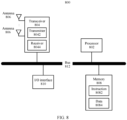
- FIG. 8 is a schematic diagram of a hardware structure of a terminal 800 according to an embodiment of the present invention.
- the terminal 800 includes a processor 802, a transceiver 804, a plurality of antennas 806, a memory 808, an I/O (input/output, Input/Output) interface 810, and a bus 812.
- the transceiver 804 further includes a transmitter 8042 and a receiver 8044.
- the memory 808 is further configured to store an instruction 8082 and data 8084.
- the processor 802, the transceiver 804, the memory 808, and the I/O interface 810 are in communication connection with each other through the bus 812.
- the plurality of antennas 806 are connected to the transceiver 804.
- the processor 802 may be a general purpose processor but is not limited to, for example, a central processing unit (CPU), or may be a dedicated processor but is not limited to, for example, a digital signal processor (Digital Signal Processor, DSP), an application-specific integrated circuit (ASIC), and a field programmable gate array (FPGA).
- the processor 802 may alternatively be a combination of a plurality of processors.
- the processor 802 may be configured to perform, for example, step 404 in the method 400 shown in FIG. 4 and an operation performed by the processing unit 604 of the terminal 600 shown in FIG. 6 .
- the processor 802 may be a processor specifically designed for performing the foregoing steps and/or operations, or may be a processor that performs the foregoing steps and/or operations by reading and executing the instruction 8082 stored in the memory 808.
- the processor 802 may need to use the data 8084 in a process of performing the foregoing steps and/or operations.
- the transceiver 804 includes the transmitter 8042 and the receiver 8044.
- the transmitter 8042 is configured to send a signal through at least one of the plurality of antennas 806.
- the transmitter 8042 is specifically configured to perform, through at least one of the plurality of antennas 806, an operation performed by the sending unit 606 of the terminal 600 shown in FIG. 6 .
- the receiver 8044 is configured to receive a signal through at least one of the plurality of antennas 806.
- the receiver 8044 is specifically configured to perform, through at least one of the plurality of antennas 806, step 402 in the method 400 shown in FIG. 4 and an operation performed by the receiving unit 602 of the terminal 600 shown in FIG. 6 .
- the memory 808 may be various types of storage media, for example, a random access memory (RAM), a read-only memory (ROM), a non-volatile RAM (NVRAM), a programmable ROM ( PROM), an erasable PROM (EPROM), an electrically erasable PROM (EEPROM), a flash memory, an optical memory, and a register.
- RAM random access memory
- ROM read-only memory
- NVRAM non-volatile RAM
- PROM programmable ROM
- EPROM erasable PROM
- EEPROM electrically erasable PROM
- flash memory an optical memory
- a register a register
- the memory 808 is specifically configured to store the instruction 8082 and the data 8084.
- the processor 802 may perform the foregoing steps and/or operations by reading and executing the instruction 8082 stored in the memory 808, and may need to use the data 8084 in a process of performing the foregoing steps and/or operations.
- the I/O interface 810 is configured to: receive an instruction and/or data from a peripheral device, and output an instruction and/or data to the peripheral device.
- the terminal 800 may further include other hardware components, which are not enumerated in this specification.
- the technical solutions provided in the embodiments of the present invention may be implemented by using a processor and a transceiver, the processor is configured to perform various processing operations but are not limited to, for example, operations such as generating, determining, judging, searching, extracting, obtaining, reading, and receiving input to-be-processed data and outputting processed data, and the transceiver is configured to perform operations such as transmitting and receiving.
- the processor may be implemented in the following manners.
- the processor is a special purpose processor.
- the processor may further include an interface circuit and a processing circuit.
- the interface circuit is configured to: receive data that needs to be processed by the processing circuit, and output a processing result of the processing circuit.
- the processing circuit is configured to perform the foregoing processing operations.
- the processor is implemented by using an architecture of a general purpose processor and a memory.
- the general purpose processor is configured to execute processing instructions stored in the memory, and the processing instructions are used to indicate the general purpose processor to perform the foregoing processing operations. It is not difficult to understand that the processing performed by the general purpose processor depends on the processing instructions stored in the memory. By modifying the processing instructions in the memory, the general purpose processor may be controlled to output different processing results.
- the general purpose processor and the memory may be integrated on a same chip.
- both the general purpose processor and the memory may be integrated on a processing chip.
- the general purpose processor and the memory may alternatively be disposed on different chips.
- the general purpose processor is disposed on a processing chip, and the memory is disposed on a storage chip.
- the technical solutions provided in the embodiments of the present invention may alternatively be implemented by using a computer-readable storage medium, and the computer-readable storage medium stores a processing instruction for implementing the technical solutions of the embodiments of the present invention.
- the instruction is provided to be read by a general purpose processing device, to complete the technical solutions provided in the embodiments of the present invention.
- the foregoing general purpose processing device should be understood as a processing device that includes necessary hardware components such as a processor and a transceiver. Operations of the hardware components depend on the processing instruction stored in the computer-readable storage medium.
- All or some of the foregoing embodiments may be implemented by using software, hardware, firmware, or any combination thereof.
- software is used to implement the embodiments, all or some of the embodiments may be implemented in a form of a computer program product.
- the computer program product includes one or more computer instructions.
- the computer may be a general purpose computer, a special purpose computer, a computer network, or another programmable apparatus.
- the computer instructions may be stored in a computer-readable storage medium or may be transmitted from a computer-readable storage medium to another computer-readable storage medium.
- the computer instructions may be transmitted from a website, computer, server, or data center to another website, computer, server, or data center in a wired (for example, a coaxial cable, an optical fiber, or a digital subscriber line (DSL)) or wireless (for example, infrared, radio, or microwave) manner.
- the computer-readable storage medium may be any usable medium accessible by the computer, or a data storage device, such as a server or a data center, integrating one or more usable media.
- the usable medium may be a magnetic medium (for example, a floppy disk, a hard disk, or a magnetic tape), an optical medium (for example, a DVD), a semiconductor medium (for example, a solid-state drive (, SSD)), or the like.
Landscapes
- Engineering & Computer Science (AREA)
- Signal Processing (AREA)
- Computer Networks & Wireless Communication (AREA)
- Physics & Mathematics (AREA)
- Mathematical Physics (AREA)
- Mobile Radio Communication Systems (AREA)
Claims (15)
- Procédé de réception d'indication de ressource de bande passante, comprenant :la réception, par un terminal (600), d'une pluralité d'éléments de signalisation de commande de liaison descendante provenant d'une pluralité de dispositifs de réseau, dans lequel un élément de signalisation de commande de liaison descendante de la pluralité d'éléments de signalisation de commande de liaison descendante transporte des informations d'indication de ressource de bande passante, et une ressource de bande passante indiquée par une pluralité d'éléments d'informations d'indication de ressource de bande passante est identique, et la pluralité d'éléments de signalisation de commande de liaison descendante sont envoyés à l'aide d'une même ressource de domaine fréquentiel ; etla détermination, par le terminal (600), de la ressource de bande passante indiquée sur la base des informations d'indication de ressource de bande passante.
- Procédé de réception de ressources de bande passante selon la revendication 1, dans lequel chacune de la ressource de bande passante indiquée par la pluralité d'éléments d'information d'indication de ressource de bande passante correspond à une numérologie, dans lequel la numérologie comprend un espacement de sous-porteuses.
- Procédé de réception de ressources de bande passante selon la revendication 1, dans lequel au moins l'une de la ressource de bande passante et de la ressource de domaine fréquentiel est une partie de bande passante, BWP.
- Procédé de réception de ressource de bande passante selon l'une quelconque des revendications 1 à 3, dans lequel chacune de la ressource de bande passante indiquée par la pluralité d'éléments d'information d'indication de ressource de bande passante correspond à un même espacement de sous-porteuses.
- Terminal (600), comprenant :un émetteur-récepteur (602), configuré pour recevoir une pluralité d'éléments de signalisation de commande de liaison descendante provenant d'une pluralité de dispositifs de réseau, dans lequel un élément de signalisation de commande de liaison descendante de la pluralité d'éléments de signalisation de commande de liaison descendante transporte des informations d'indication de ressource de bande passante, et une ressource de bande passante indiquée par une pluralité d'éléments d'informations d'indication de ressource de bande passante est identique, et la pluralité d'éléments de signalisation de commande de liaison descendante sont envoyés à l'aide d'une même ressource de domaine fréquentiel ; etun processeur (604), configuré pour déterminer la ressource de bande passante indiquée sur la base des informations d'indication de ressource de bande passante.
- Terminal selon la revendication 5, dans lequel chacune de la ressource de bande passante indiquée par la pluralité d'éléments d'informations d'indication de ressource de bande passante correspond à une numérologie, dans lequel la numérologie comprend un espacement de sous-porteuses.
- Terminal selon la revendication 5, dans lequel au moins l'une de la ressource de bande passante et de la ressource de domaine fréquentiel est une partie de bande passante, BWP.
- Terminal selon l'une quelconque des revendications 5 à 7, dans lequel chacune de la ressource de bande passante indiquée par la pluralité d'informations d'indication de ressource de bande passante correspond à un même espacement de sous-porteuses.
- Procédé de transmission d'indication de ressource de bande passante, comprenant :l'obtention, par un dispositif de réseau (500), des informations d'indication de ressource de bande passante transportées dans une première signalisation de commande de liaison descendante envoyée par un autre dispositif de réseau à un terminal ; ou la notification à un autre dispositif de réseau des informations d'indication de ressource de bande passante transportées dans une seconde signalisation de commande de liaison descendante envoyée par le dispositif de réseau à un terminal ;l'envoi, par le dispositif de réseau (500), de la seconde signalisation de commande de liaison descendante au terminal, dans lequel la seconde signalisation de commande de liaison descendante transporte les informations d'indication de ressource de bande passante, et une ressource de bande passante indiquée par les informations d'indication de ressource de bande passante est la même qu'une ressource de bande passante indiquée par les informations d'indication de ressource de bande passante transportées dans la première signalisation de commande de liaison descendante envoyée par l'autre dispositif de réseau au terminal, et caractérisé en ce que :
la seconde signalisation de commande de liaison descendante envoyée par le dispositif de réseau et la première signalisation de commande de liaison descendante envoyée par l'autre dispositif de réseau sont envoyées à l'aide d'une même ressource de domaine fréquentiel. - Procédé de transmission de ressource de bande passante selon la revendication 9, dans lequel la ressource de bande passante indiquée par les informations d'indication de ressource de bande passante correspond à une numérologie, dans lequel la numérologie comprend un espacement de sous-porteuses.
- Procédé de transmission de ressources de bande passante selon la revendication 9, dans lequel au moins l'une de la ressource de bande passante et la ressource de domaine fréquentiel est une partie de bande passante, BWP.
- Dispositif de réseau (500), comprenant :un émetteur-récepteur, configuré pour obtenir des informations d'indication de ressource de bande passante transportées dans une première signalisation de commande de liaison descendante envoyée par un autre dispositif de réseau à un terminal ; ounotifier à un autre dispositif de réseau des informations d'indication de ressource de bande passante transportées dans une seconde signalisation de commande de liaison descendante envoyée par l'émetteur-récepteur à un terminal ;l'émetteur-récepteur est également configuré pour envoyer la seconde signalisation de commande de liaison descendante au terminal, dans lequel la seconde signalisation de commande de liaison descendante transporte les informations d'indication de ressource de bande passante, et une ressource de bande passante indiquée par les informations d'indication de ressource de bande passante est la même qu'une ressource de bande passante indiquée par les informations d'indication de ressource de bande passante transportées dans la première signalisation de commande de liaison descendante envoyée par l'autre dispositif de réseau au terminal ; et caractérisé en ce que :
la seconde signalisation de commande de liaison descendante est envoyée à l'aide d'une même ressource de domaine fréquentiel que la première signalisation de commande de liaison descendante envoyée par l'autre dispositif de réseau. - Dispositif de réseau selon la revendication 12, dans lequel la ressource de bande passante indiquée par les informations d'indication de ressource de bande passante correspond à une numérologie, dans lequel la numérologie comprend un espacement de sous-porteuses.
- Dispositif de réseau selon la revendication 12, dans lequel au moins l'une de la ressource de bande passante et de la ressource de domaine fréquentiel est une partie de bande passante, BWP.
- Support de stockage lisible par ordinateur, comprenant un programme informatique, dans lequel, lorsque le programme informatique est exécuté sur un ordinateur, l'ordinateur est capable de mettre en œuvre le procédé selon l'une quelconque des revendications 1 à 4, ou le procédé selon l'une quelconque des revendications 9 à 11.
Applications Claiming Priority (3)
| Application Number | Priority Date | Filing Date | Title |
|---|---|---|---|
| CN201810910947 | 2018-08-10 | ||
| CN201910252616.0A CN110831198B (zh) | 2018-08-10 | 2019-03-29 | 带宽资源切换方法、指示带宽资源切换方法、终端和网络设备 |
| PCT/CN2019/099698 WO2020030020A1 (fr) | 2018-08-10 | 2019-08-08 | Procédé de commutation de partie de bande passante, procédé d'indication de commutation de partie de bande passante, terminal et appareil de réseau |
Publications (3)
| Publication Number | Publication Date |
|---|---|
| EP3836677A1 EP3836677A1 (fr) | 2021-06-16 |
| EP3836677A4 EP3836677A4 (fr) | 2021-11-03 |
| EP3836677B1 true EP3836677B1 (fr) | 2025-03-05 |
Family
ID=69547594
Family Applications (1)
| Application Number | Title | Priority Date | Filing Date |
|---|---|---|---|
| EP19846435.6A Active EP3836677B1 (fr) | 2018-08-10 | 2019-08-08 | Procédé d'indication de bande passante, terminal et appareil de réseau |
Country Status (3)
| Country | Link |
|---|---|
| US (1) | US11924815B2 (fr) |
| EP (1) | EP3836677B1 (fr) |
| CN (1) | CN110831198B (fr) |
Families Citing this family (25)
| Publication number | Priority date | Publication date | Assignee | Title |
|---|---|---|---|---|
| US11368956B2 (en) * | 2018-04-05 | 2022-06-21 | Qualcomm Incorporated | Radio link management under bandwidth part switching |
| CN109496455B (zh) * | 2018-10-19 | 2023-08-22 | 北京小米移动软件有限公司 | 资源切换方法、资源分配方法、装置、设备及系统 |
| US20210126816A1 (en) * | 2020-01-09 | 2021-04-29 | Alexei Davydov | Sounding reference signal (srs) transmission with bandwidth part (bwp) switching |
| CN114747278B (zh) * | 2020-02-24 | 2024-07-30 | Oppo广东移动通信有限公司 | 下行控制信道的检测方法及相关装置 |
| WO2021168628A1 (fr) * | 2020-02-24 | 2021-09-02 | Oppo广东移动通信有限公司 | Procédé de commutation de groupe d'espaces de recherche, dispositif terminal et dispositif de réseau |
| US12395975B2 (en) * | 2020-04-06 | 2025-08-19 | Nokia Technologies Oy | First and second apparatus, method to operate the first and second apparatus |
| CN113541894B (zh) * | 2020-04-16 | 2023-02-21 | 维沃移动通信有限公司 | 一种资源确定方法及设备 |
| CN111869268B (zh) * | 2020-06-04 | 2023-07-25 | 北京小米移动软件有限公司 | 信息配置方法、装置、设备及可读存储介质 |
| CN111818603B (zh) * | 2020-06-19 | 2022-07-19 | 中国信息通信研究院 | 一种波束切换的方法、设备和系统 |
| WO2022027488A1 (fr) * | 2020-08-06 | 2022-02-10 | Oppo广东移动通信有限公司 | Procédé de communication sans fil, dispositif terminal et dispositif de réseau |
| CN114071748B (zh) * | 2020-08-07 | 2026-03-27 | 大唐移动通信设备有限公司 | 信号传输方法、终端和网络设备 |
| CN114258132A (zh) * | 2020-09-22 | 2022-03-29 | 华为技术有限公司 | 资源配置方法及装置 |
| CN114501569B (zh) * | 2020-10-23 | 2024-03-15 | 大唐移动通信设备有限公司 | 数据传输方法、装置、终端及网络侧设备 |
| CN114501489B (zh) * | 2020-11-12 | 2026-02-03 | 维沃移动通信有限公司 | 节能指示方法、装置、设备及可读存储介质 |
| CN116671218B (zh) * | 2021-01-18 | 2025-05-13 | Oppo广东移动通信有限公司 | 配置srs传输资源的方法、终端设备及网络设备 |
| US12004174B2 (en) * | 2021-05-28 | 2024-06-04 | Qualcomm Incorporated | Support for an increased quantity of sidelink configured grants |
| CN114071583B (zh) * | 2021-11-04 | 2024-09-17 | 中国联合网络通信集团有限公司 | 一种分布式网络架构的带宽选择方法及装置 |
| CN114071569B (zh) * | 2021-11-04 | 2023-06-16 | 中国联合网络通信集团有限公司 | 一种数据传输方法、装置和电子设备 |
| CN116939853A (zh) * | 2022-04-08 | 2023-10-24 | 大唐移动通信设备有限公司 | 一种信息处理方法、装置和可读存储介质 |
| CN114585096B (zh) * | 2022-05-05 | 2022-10-18 | 深圳国人无线通信有限公司 | 一种通过bwp切换功能降低干扰的方法和系统 |
| CN117395794A (zh) * | 2022-06-30 | 2024-01-12 | 展讯通信(上海)有限公司 | 通信方法及装置 |
| US12476766B2 (en) * | 2022-08-03 | 2025-11-18 | Qualcomm Incorporated | Adaptation of a first available resource block and resource block group size for full-duplex communications |
| CN116015584B (zh) * | 2022-12-09 | 2025-09-02 | 大连市共进科技有限公司 | 基于dci信令的bwp切换方法、装置和系统 |
| CN116456491B (zh) * | 2023-03-28 | 2024-06-07 | 江苏亨鑫无线技术有限公司 | 一种下行控制信息通信方法及相关设备 |
| CN116347622A (zh) * | 2023-03-29 | 2023-06-27 | 联想(北京)有限公司 | 一种网络侧网元控制方法、装置及服务器 |
Family Cites Families (18)
| Publication number | Priority date | Publication date | Assignee | Title |
|---|---|---|---|---|
| US8542605B2 (en) * | 2009-10-15 | 2013-09-24 | Qualcomm Incorporated | System and method for allocating resources in an extended bandwidth wireless network |
| US20120269146A1 (en) * | 2009-11-02 | 2012-10-25 | Kari Pekka Pajukoski | Uplink Channel Sounding |
| CN102083223A (zh) * | 2010-03-05 | 2011-06-01 | 大唐移动通信设备有限公司 | 一种发送dci和上行传输的方法、系统及装置 |
| CN103298119B (zh) * | 2012-02-29 | 2016-04-06 | 电信科学技术研究院 | 一种时频资源的指示及确认方法和装置 |
| CN110336654B (zh) * | 2013-03-28 | 2024-01-30 | 华为技术有限公司 | 带宽分配方法、装置、用户设备和基站 |
| US10462771B2 (en) * | 2013-04-04 | 2019-10-29 | Lg Electronics Inc. | Receiving method and user device in small-scale cell |
| CN105450374B (zh) * | 2014-08-25 | 2018-08-31 | 联想(北京)有限公司 | 一种信息处理方法、系统及基站 |
| CN113692059B (zh) | 2016-05-30 | 2023-12-15 | 北京三星通信技术研究有限公司 | 无线通信系统中的方法和设备 |
| IL267418B (en) * | 2016-12-23 | 2022-07-01 | Guangdong Oppo Mobile Telecommunications Corp Ltd | Method and device for transmitting data |
| ES2927069T3 (es) * | 2016-12-27 | 2022-11-02 | 5G Ip Holdings Llc | Método para señalizar indicadores de parte de ancho de banda (BWP) y equipo de comunicación por radio que utiliza el mismo |
| KR102164967B1 (ko) * | 2017-01-06 | 2020-10-13 | 한국전자통신연구원 | 통신 시스템에서 제어 채널의 송수신 방법 및 장치 |
| JP6777813B2 (ja) | 2017-07-28 | 2020-10-28 | エルジー エレクトロニクス インコーポレイティド | 無線通信システムにおいてbwp動作を遂行する方法、及びこのための装置 |
| CN107872891B (zh) * | 2017-11-14 | 2021-12-21 | 宇龙计算机通信科技(深圳)有限公司 | 资源调度方法、装置、网络设备及终端 |
| KR20200110359A (ko) * | 2018-02-12 | 2020-09-23 | 삼성전자주식회사 | 상향링크 정보를 전송하는 방법 및 장치 |
| CN112584497B (zh) * | 2019-09-27 | 2022-08-12 | 维沃移动通信有限公司 | 先听后发lbt子带划分方法、装置、设备及介质 |
| WO2021056525A1 (fr) * | 2019-09-29 | 2021-04-01 | Nokia Shanghai Bell Co., Ltd. | Attribution de bande passante étendue |
| CN114731635B (zh) * | 2019-11-15 | 2025-10-17 | 联想(北京)有限公司 | 用于无线通信的方法及设备 |
| US11889522B2 (en) * | 2021-07-30 | 2024-01-30 | Qualcomm Incorporated | Partial control resource set handling |
-
2019
- 2019-03-29 CN CN201910252616.0A patent/CN110831198B/zh active Active
- 2019-08-08 EP EP19846435.6A patent/EP3836677B1/fr active Active
-
2021
- 2021-02-10 US US17/172,919 patent/US11924815B2/en active Active
Also Published As
| Publication number | Publication date |
|---|---|
| EP3836677A4 (fr) | 2021-11-03 |
| CN110831198A (zh) | 2020-02-21 |
| CN110831198B (zh) | 2024-02-02 |
| US20210204288A1 (en) | 2021-07-01 |
| US11924815B2 (en) | 2024-03-05 |
| EP3836677A1 (fr) | 2021-06-16 |
Similar Documents
| Publication | Publication Date | Title |
|---|---|---|
| EP3836677B1 (fr) | Procédé d'indication de bande passante, terminal et appareil de réseau | |
| US10511411B2 (en) | Method for configuring channel state information reporting band and communications apparatus | |
| EP3847858B1 (fr) | Techniques pour la détermination d'un état de configuration d'une transmission | |
| US11438965B2 (en) | User equipment in wireless communication system | |
| WO2020030020A1 (fr) | Procédé de commutation de partie de bande passante, procédé d'indication de commutation de partie de bande passante, terminal et appareil de réseau | |
| EP3639456B1 (fr) | Configuration de sondage et de mesure spécifique à une cellule de systèmes de communication sans fil | |
| KR102200645B1 (ko) | 리소스 구성 방법 및 장치 | |
| WO2014197493A1 (fr) | Unité centrale de traitement et procédés pour prendre en charge une transmission multipoint coordonnée dans un réseau lte | |
| US20210111773A1 (en) | Method for feedback of correlation of beams in wireless communication system and user equipment | |
| CN112771968A (zh) | 传输上行反馈信息的方法、终端设备和网络设备 | |
| EP3609114A1 (fr) | Procédé et appareil de mesure de canal | |
| CN112703699A (zh) | 传输数据信道的方法和终端设备 | |
| US10924168B2 (en) | Reference signal sending and receiving methods and related device | |
| US20200128547A1 (en) | Frequency Band Indication Method, Frequency Band Determining Method, Transmit End Device, And Receive End Device | |
| KR20250149741A (ko) | Sbfd 동작을 위한 시간/주파수 도메인에서의 자원 할당 | |
| WO2022087439A1 (fr) | Compression de livre de codes avec codage avec perte pour des événements à faible probabilité | |
| US11290906B2 (en) | Channel measurement method | |
| EP4179684A1 (fr) | Retard spécifique d'espace de recherche entre un canal de commande de liaison descendante et des données de liaison descendante/liaison montante correspondantes | |
| CN109756255B (zh) | 一种信道测量方法和用户设备 | |
| JP2024505351A (ja) | ワイヤレス通信におけるアップリンク制御チャネル反復の指示 | |
| EP3703296A1 (fr) | Équipement d'utilisateur et dispositif d'accès | |
| US12549957B2 (en) | Terminal and communication method | |
| WO2019105215A1 (fr) | Procédé, dispositif et système d'indication de transmission et support de stockage | |
| EP3528397A1 (fr) | Procédé, dispositif et système de configuration de précodage | |
| CN114208236A (zh) | 终端、基站以及通信方法 |
Legal Events
| Date | Code | Title | Description |
|---|---|---|---|
| STAA | Information on the status of an ep patent application or granted ep patent |
Free format text: STATUS: THE INTERNATIONAL PUBLICATION HAS BEEN MADE |
|
| PUAI | Public reference made under article 153(3) epc to a published international application that has entered the european phase |
Free format text: ORIGINAL CODE: 0009012 |
|
| STAA | Information on the status of an ep patent application or granted ep patent |
Free format text: STATUS: REQUEST FOR EXAMINATION WAS MADE |
|
| 17P | Request for examination filed |
Effective date: 20210310 |
|
| AK | Designated contracting states |
Kind code of ref document: A1 Designated state(s): AL AT BE BG CH CY CZ DE DK EE ES FI FR GB GR HR HU IE IS IT LI LT LU LV MC MK MT NL NO PL PT RO RS SE SI SK SM TR |
|
| A4 | Supplementary search report drawn up and despatched |
Effective date: 20210930 |
|
| RIC1 | Information provided on ipc code assigned before grant |
Ipc: H04W 72/04 20090101AFI20210924BHEP |
|
| DAV | Request for validation of the european patent (deleted) | ||
| DAX | Request for extension of the european patent (deleted) | ||
| STAA | Information on the status of an ep patent application or granted ep patent |
Free format text: STATUS: EXAMINATION IS IN PROGRESS |
|
| 17Q | First examination report despatched |
Effective date: 20230404 |
|
| REG | Reference to a national code |
Ref legal event code: R079 Ipc: H04L0005000000 Ref country code: DE Ref legal event code: R079 Ref document number: 602019066997 Country of ref document: DE Free format text: PREVIOUS MAIN CLASS: H04W0072040000 Ipc: H04L0005000000 |
|
| GRAP | Despatch of communication of intention to grant a patent |
Free format text: ORIGINAL CODE: EPIDOSNIGR1 |
|
| STAA | Information on the status of an ep patent application or granted ep patent |
Free format text: STATUS: GRANT OF PATENT IS INTENDED |
|
| RIC1 | Information provided on ipc code assigned before grant |
Ipc: H04W 72/0453 20230101ALI20241018BHEP Ipc: H04W 36/06 20090101ALI20241018BHEP Ipc: H04L 5/00 20060101AFI20241018BHEP |
|
| INTG | Intention to grant announced |
Effective date: 20241031 |
|
| GRAS | Grant fee paid |
Free format text: ORIGINAL CODE: EPIDOSNIGR3 |
|
| GRAA | (expected) grant |
Free format text: ORIGINAL CODE: 0009210 |
|
| STAA | Information on the status of an ep patent application or granted ep patent |
Free format text: STATUS: THE PATENT HAS BEEN GRANTED |
|
| AK | Designated contracting states |
Kind code of ref document: B1 Designated state(s): AL AT BE BG CH CY CZ DE DK EE ES FI FR GB GR HR HU IE IS IT LI LT LU LV MC MK MT NL NO PL PT RO RS SE SI SK SM TR |
|
| REG | Reference to a national code |
Ref country code: GB Ref legal event code: FG4D |
|
| REG | Reference to a national code |
Ref country code: CH Ref legal event code: EP |
|
| REG | Reference to a national code |
Ref country code: DE Ref legal event code: R096 Ref document number: 602019066997 Country of ref document: DE |
|
| REG | Reference to a national code |
Ref country code: IE Ref legal event code: FG4D |
|
| PG25 | Lapsed in a contracting state [announced via postgrant information from national office to epo] |
Ref country code: RS Free format text: LAPSE BECAUSE OF FAILURE TO SUBMIT A TRANSLATION OF THE DESCRIPTION OR TO PAY THE FEE WITHIN THE PRESCRIBED TIME-LIMIT Effective date: 20250605 |
|
| PG25 | Lapsed in a contracting state [announced via postgrant information from national office to epo] |
Ref country code: FI Free format text: LAPSE BECAUSE OF FAILURE TO SUBMIT A TRANSLATION OF THE DESCRIPTION OR TO PAY THE FEE WITHIN THE PRESCRIBED TIME-LIMIT Effective date: 20250305 |
|
| REG | Reference to a national code |
Ref country code: NL Ref legal event code: MP Effective date: 20250305 |
|
| PG25 | Lapsed in a contracting state [announced via postgrant information from national office to epo] |
Ref country code: ES Free format text: LAPSE BECAUSE OF FAILURE TO SUBMIT A TRANSLATION OF THE DESCRIPTION OR TO PAY THE FEE WITHIN THE PRESCRIBED TIME-LIMIT Effective date: 20250305 |
|
| REG | Reference to a national code |
Ref country code: LT Ref legal event code: MG9D |
|
| PG25 | Lapsed in a contracting state [announced via postgrant information from national office to epo] |
Ref country code: NO Free format text: LAPSE BECAUSE OF FAILURE TO SUBMIT A TRANSLATION OF THE DESCRIPTION OR TO PAY THE FEE WITHIN THE PRESCRIBED TIME-LIMIT Effective date: 20250605 |
|
| PG25 | Lapsed in a contracting state [announced via postgrant information from national office to epo] |
Ref country code: HR Free format text: LAPSE BECAUSE OF FAILURE TO SUBMIT A TRANSLATION OF THE DESCRIPTION OR TO PAY THE FEE WITHIN THE PRESCRIBED TIME-LIMIT Effective date: 20250305 |
|
| PG25 | Lapsed in a contracting state [announced via postgrant information from national office to epo] |
Ref country code: LV Free format text: LAPSE BECAUSE OF FAILURE TO SUBMIT A TRANSLATION OF THE DESCRIPTION OR TO PAY THE FEE WITHIN THE PRESCRIBED TIME-LIMIT Effective date: 20250305 |
|
| PG25 | Lapsed in a contracting state [announced via postgrant information from national office to epo] |
Ref country code: GR Free format text: LAPSE BECAUSE OF FAILURE TO SUBMIT A TRANSLATION OF THE DESCRIPTION OR TO PAY THE FEE WITHIN THE PRESCRIBED TIME-LIMIT Effective date: 20250606 |
|
| REG | Reference to a national code |
Ref country code: AT Ref legal event code: MK05 Ref document number: 1773953 Country of ref document: AT Kind code of ref document: T Effective date: 20250305 |
|
| PG25 | Lapsed in a contracting state [announced via postgrant information from national office to epo] |
Ref country code: NL Free format text: LAPSE BECAUSE OF FAILURE TO SUBMIT A TRANSLATION OF THE DESCRIPTION OR TO PAY THE FEE WITHIN THE PRESCRIBED TIME-LIMIT Effective date: 20250305 |
|
| PG25 | Lapsed in a contracting state [announced via postgrant information from national office to epo] |
Ref country code: SE Free format text: LAPSE BECAUSE OF FAILURE TO SUBMIT A TRANSLATION OF THE DESCRIPTION OR TO PAY THE FEE WITHIN THE PRESCRIBED TIME-LIMIT Effective date: 20250305 |
|
| PG25 | Lapsed in a contracting state [announced via postgrant information from national office to epo] |
Ref country code: SM Free format text: LAPSE BECAUSE OF FAILURE TO SUBMIT A TRANSLATION OF THE DESCRIPTION OR TO PAY THE FEE WITHIN THE PRESCRIBED TIME-LIMIT Effective date: 20250305 |
|
| PG25 | Lapsed in a contracting state [announced via postgrant information from national office to epo] |
Ref country code: PT Free format text: LAPSE BECAUSE OF FAILURE TO SUBMIT A TRANSLATION OF THE DESCRIPTION OR TO PAY THE FEE WITHIN THE PRESCRIBED TIME-LIMIT Effective date: 20250707 |
|
| PGFP | Annual fee paid to national office [announced via postgrant information from national office to epo] |
Ref country code: DE Payment date: 20250702 Year of fee payment: 7 |
|
| PG25 | Lapsed in a contracting state [announced via postgrant information from national office to epo] |
Ref country code: IT Free format text: LAPSE BECAUSE OF FAILURE TO SUBMIT A TRANSLATION OF THE DESCRIPTION OR TO PAY THE FEE WITHIN THE PRESCRIBED TIME-LIMIT Effective date: 20250305 Ref country code: PL Free format text: LAPSE BECAUSE OF FAILURE TO SUBMIT A TRANSLATION OF THE DESCRIPTION OR TO PAY THE FEE WITHIN THE PRESCRIBED TIME-LIMIT Effective date: 20250305 |
|
| PGFP | Annual fee paid to national office [announced via postgrant information from national office to epo] |
Ref country code: BG Payment date: 20250715 Year of fee payment: 7 Ref country code: GB Payment date: 20250703 Year of fee payment: 7 |
|
| PG25 | Lapsed in a contracting state [announced via postgrant information from national office to epo] |
Ref country code: AT Free format text: LAPSE BECAUSE OF FAILURE TO SUBMIT A TRANSLATION OF THE DESCRIPTION OR TO PAY THE FEE WITHIN THE PRESCRIBED TIME-LIMIT Effective date: 20250305 |
|
| PGFP | Annual fee paid to national office [announced via postgrant information from national office to epo] |
Ref country code: FR Payment date: 20250703 Year of fee payment: 7 |
|
| PG25 | Lapsed in a contracting state [announced via postgrant information from national office to epo] |
Ref country code: EE Free format text: LAPSE BECAUSE OF FAILURE TO SUBMIT A TRANSLATION OF THE DESCRIPTION OR TO PAY THE FEE WITHIN THE PRESCRIBED TIME-LIMIT Effective date: 20250305 Ref country code: CZ Free format text: LAPSE BECAUSE OF FAILURE TO SUBMIT A TRANSLATION OF THE DESCRIPTION OR TO PAY THE FEE WITHIN THE PRESCRIBED TIME-LIMIT Effective date: 20250305 |
|
| PGFP | Annual fee paid to national office [announced via postgrant information from national office to epo] |
Ref country code: IE Payment date: 20250702 Year of fee payment: 7 |
|
| PG25 | Lapsed in a contracting state [announced via postgrant information from national office to epo] |
Ref country code: RO Free format text: LAPSE BECAUSE OF FAILURE TO SUBMIT A TRANSLATION OF THE DESCRIPTION OR TO PAY THE FEE WITHIN THE PRESCRIBED TIME-LIMIT Effective date: 20250305 |
|
| PG25 | Lapsed in a contracting state [announced via postgrant information from national office to epo] |
Ref country code: SK Free format text: LAPSE BECAUSE OF FAILURE TO SUBMIT A TRANSLATION OF THE DESCRIPTION OR TO PAY THE FEE WITHIN THE PRESCRIBED TIME-LIMIT Effective date: 20250305 |
|
| PG25 | Lapsed in a contracting state [announced via postgrant information from national office to epo] |
Ref country code: IS Free format text: LAPSE BECAUSE OF FAILURE TO SUBMIT A TRANSLATION OF THE DESCRIPTION OR TO PAY THE FEE WITHIN THE PRESCRIBED TIME-LIMIT Effective date: 20250705 |
|
| REG | Reference to a national code |
Ref country code: DE Ref legal event code: R097 Ref document number: 602019066997 Country of ref document: DE |
|
| PLBE | No opposition filed within time limit |
Free format text: ORIGINAL CODE: 0009261 |
|
| STAA | Information on the status of an ep patent application or granted ep patent |
Free format text: STATUS: NO OPPOSITION FILED WITHIN TIME LIMIT |
|
| PG25 | Lapsed in a contracting state [announced via postgrant information from national office to epo] |
Ref country code: DK Free format text: LAPSE BECAUSE OF FAILURE TO SUBMIT A TRANSLATION OF THE DESCRIPTION OR TO PAY THE FEE WITHIN THE PRESCRIBED TIME-LIMIT Effective date: 20250305 |
|
| REG | Reference to a national code |
Ref country code: CH Ref legal event code: L10 Free format text: ST27 STATUS EVENT CODE: U-0-0-L10-L00 (AS PROVIDED BY THE NATIONAL OFFICE) Effective date: 20260114 |
|
| 26N | No opposition filed |
Effective date: 20251208 |
|
| REG | Reference to a national code |
Ref country code: CH Ref legal event code: H13 Free format text: ST27 STATUS EVENT CODE: U-0-0-H10-H13 (AS PROVIDED BY THE NATIONAL OFFICE) Effective date: 20260324 |
|
| PG25 | Lapsed in a contracting state [announced via postgrant information from national office to epo] |
Ref country code: MC Free format text: LAPSE BECAUSE OF FAILURE TO SUBMIT A TRANSLATION OF THE DESCRIPTION OR TO PAY THE FEE WITHIN THE PRESCRIBED TIME-LIMIT Effective date: 20250305 |
|
| PG25 | Lapsed in a contracting state [announced via postgrant information from national office to epo] |
Ref country code: LU Free format text: LAPSE BECAUSE OF NON-PAYMENT OF DUE FEES Effective date: 20250808 |
|
| PG25 | Lapsed in a contracting state [announced via postgrant information from national office to epo] |
Ref country code: CH Free format text: LAPSE BECAUSE OF NON-PAYMENT OF DUE FEES Effective date: 20250831 |