EP3836744B1 - Zellulares kommunikationssystem - Google Patents
Zellulares kommunikationssystem Download PDFInfo
- Publication number
- EP3836744B1 EP3836744B1 EP20207584.2A EP20207584A EP3836744B1 EP 3836744 B1 EP3836744 B1 EP 3836744B1 EP 20207584 A EP20207584 A EP 20207584A EP 3836744 B1 EP3836744 B1 EP 3836744B1
- Authority
- EP
- European Patent Office
- Prior art keywords
- signal
- small cell
- unit
- band
- common controller
- Prior art date
- Legal status (The legal status is an assumption and is not a legal conclusion. Google has not performed a legal analysis and makes no representation as to the accuracy of the status listed.)
- Active
Links
Images






Classifications
-
- H—ELECTRICITY
- H04—ELECTRIC COMMUNICATION TECHNIQUE
- H04W—WIRELESS COMMUNICATION NETWORKS
- H04W88/00—Devices specially adapted for wireless communication networks, e.g. terminals, base stations or access point devices
- H04W88/08—Access point devices
- H04W88/085—Access point devices with remote components
Definitions
- the following description relates to a cellular communication technology, and more particularly, to a distributed antenna system (DAS) having a set of small cells as a source.
- DAS distributed antenna system
- a base transceiver station BTS
- BTS base transceiver station
- RRH remote radio head
- CPRI common public radio interface
- DAS distributed antenna system
- a typical analog DAS includes a headend unit and remote units.
- the headend unit is connected to BTSs or RRH devices via coaxial cables, converts radio frequency (RF) signal inputs from the connected BTSs or RRH devices into optical RF signals, and outputs the optical RF signals, and the remote units are connected to the headend unit via optical fibers and distribute downlink optical RF signals to wireless terminals.
- RF radio frequency
- Such an analog DAS is difficult to reconfigure once it has been deployed, and cannot scale dynamically to a required service capacity.
- Small cells are low-powered wireless access BTSs, which are each defined as having an operational range from at least 10 meters to a few hundred meters. Small cells are classified as femtocells, picocells, metrocells, and microcells according to their usage range and purpose of use. In addition, the classification of small cells may be made according to an installation site and purpose of service, and small cells for home, enterprise, urban areas, and rural areas may exist.
- US 2016135175 discloses a system for managing a small cell telecommunication system servicing multiple network operators.
- the management sub-system disclosed in US 2016135175 encompasses a controller, multiple baseband units and a transport module.
- Each of the baseband units includes one processor, I/Q modules, PHY modules and MAC modules.
- the output of the baseband units is connected to a transport module encompassing several mixers, which combine the I and Q components of the complex digital signal, a combining module and a backplane.
- the backplane routes the signal to one or more of the remote antenna units.
- the following description relates to a cellular communication system, which uses an analog distributed antenna system (DAS) that is readily reconfigurable according to a required service capacity.
- DAS distributed antenna system
- the following description relates to a cellular communication system, which uses an analog DAS whose capacity is scalable according to a required service capacity.
- the following description relates to a cellular communication system, which uses an analog DAS that is readily reconfigurable according to a required service capacity while minimizing addition of hardware devices or components at the customer sites.
- each block of the block diagrams may represent a physical element, and in some cases, may represent part of a function of one physical element or a logical representation of a function over a number of physical elements.
- a block or a portion of a block may sometimes be a set of program instructions. All or some of the blocks may be implemented by hardware, software, or a combination thereof.
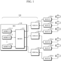
- FIG. 1 is a diagram illustrating an example of an analog distributed antenna system (DAS) to which the present invention is applicable.
- the analog DAS includes a headend unit 100 and a plurality of remote units 150.
- the remote units are represented as remote optical units 150.
- the headend unit 100 and the plurality of remote optical units 150 are connected via optical cables.
- the term "remote unit" indicates that the headend unit may be connected to the plurality of remote optical units 150 via coaxial cables or other analog cables instead of the optical cables.
- the headend unit 100 mixes and converts a plurality of radio frequency (RF) signals from a plurality of base transceiver stations (BTSs) into an optical RF signal.
- RF radio frequency
- Each of the remote optical units 150 is disposed at each site, converts the optical RF signal received from the headend unit into an electrical RF signal, and transmits the electrical RF signal to the antenna.
- a description regarding a downlink signal may be applied to an uplink signal in a symmetrical manner.
- the headend unit 100 includes a base station interface unit (BIU) 110 and an optical distribution unit (ODU) 130.
- the BIU 110 includes a plurality of base-station signal driving units 111, which receive a signal of each band from a BTS, up/down convert the band of the signal if necessary, and output the resultant signal, and a combine-divider 113, which mixes RF signals input from the plurality of base-station signal driving units and output a resultant signal.
- the base-station signal driving unit is denoted as a main driver BTS unit (MDBU) and the combine-divider 113 is denoted as a main combiner/divider unit (MCDU).
- MDBU main driver BTS unit
- MCDU main combiner/divider unit
- the base-station signal driving units 111 are connected to an output of BTS equipment of each mobile communication service operator via coaxial cables.
- the present invention is not limited to the above, and the base-station signal driving units 111 may also be connected via optical cables.
- the base-station driving units 111 may deal with different frequency bands or different signal specifications according to specifications of a mobile communication service operator or specifications of BTS equipment.
- the combine-divider 113 has a plurality of outputs, through each of which a mixture of the RF signals output from the base-station signal driving units 111 is output according to needs of the remote optical units 150.
- the ODU 130 converts the RF signal output from the combine-divider 113 into an optical RF signal, and distributes and outputs the optical RF signal through a plurality of output ports.
- the remote optical unit 150 receives the optical RF signals from the ODU 130.
- Each output port of the ODU 130 may be connected with the remote optical unit 150.
- an ODU 130-1 is connected with remote optical units 150-1, 150-2, and 150-3.
- an ODU 130-2 is connected with remote optical units 150-4 and 150-5.
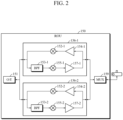
- FIG. 2 is a block diagram illustrating an example of a configuration of a remote optical unit of FIG. 1 .
- the remote optical unit 150 includes three types of modules which are a photoelectric conversion unit 151 configured to convert the optical RF signals received from the ODU 130 into electrical RF signals, a plurality of remote drive units (RDUs) 156-1 and 156-2, and a combine unit configured to combine signals generated from the RDUs.
- the remote optical units 150 may include the plurality of RDUs.
- Each of the RDUs 156-1 and 156-2 includes a bandpass filter 153 which filters only a required band in an RF signal on a downlink path, a modulation/demodulation unit 155 which up/down converts a band of the filtered RF signal when necessary and outputs a resultant signal, and a power amplifier 157.
- Each of the RDUs 156-1 and 156-2 includes a low noise amplifier 154 which amplifies a signal from an antenna on an uplink path and a modulation/demodulation unit 152 which up/down converts a band of output from the low noise amplifier 154 and outputs a resultant signal when necessary.
- a plurality of RF signals of different bands may be multiplexed and transmitted through a single optical fiber.
- the first part processed by the upper protocol processor 211 may be a media access control (MAC) layer and/or higher in the protocol stack of the small cell.
- the remaining second part processed by the lower protocol processor may be a physical (PHY) layer in the protocol stack of the small cell.
- PHY physical
- LTE radio interface protocols In regard to long term evolution (LTE) radio interface protocols, a number of technical materials have been available, for example, there is the article entitled " Overview of LTE Radio Interface and Radio Network Architecture for High Speed, High Capacity and Low Latency" which was published on pages 10-19 in NTT TOCOMO Technical Journal Vol.13 No.1 .
- the LTE radio interface protocols may be classified as radio resource control (RRC), packet data convergence protocol (PDCP), radio link control (RLC), MAC, and PHY layer protocols.
- RRC radio resource control
- PDCP packet data convergence protocol
- RLC radio link control
- MAC media access control
- PHY layer protocols PHY layer protocols.
- PDCP, RLC, and MAC layers that correspond to a second layer in seven layers of open system interconnection (OSI)
- OSI open system interconnection
- the PDCP layer receives an RRC packet and processes header compression, a cipher of an RRC message, and integrity protection.
- the RLC layer segments and concatenates protocol data unit (PDU) packets from the PDCP layer to generate an RLC PDU with an appropriate packet size.
- the RLC layer performs automatic repeat request (ARQ) control according to a response from a receiving side.
- ARQ automatic repeat request
- the MAC layer performs scheduling of shared channel resources. Also, the MAC layer processes a hybrid ARQ (HARQ).
- HARQ hybrid ARQ
- the PHY layer performs cell search and channel-dependent scheduling in a frequency domain, and performs a random access procedure when making a call.
- the illustrated aspect is described as an example of an LTE system, the present invention is not limited thereto and can be applied to general mobile communication technologies or a combination thereof, as is typical for a DAS.
- Virtualization technique of a radio access network which has been recently discussed in the Small Cell Forum (http://www.smallcellforum.org), may be considered as a reference technique, although it is not directly related to the present invention.
- some upper layers among RAN layers for mobile communication are virtualized and implemented in cloud space in a software manner, and the remaining layers are implemented as physical network functions.
- function splitting is in progress regarding which layers are to be virtualized and which layers are to be implemented as physical network functions among the RAN layers. According to the ongoing discussion, because splitting is performed on higher layers, transport costs are advantageously reduced, while RF gains are also reduced.
- function splitting in RAN virtualization which can secure smooth communications between virtualized functional blocks and physical lower layer functional blocks include bandwidth and latency.
- function splitting between a MAC layer and a PHY layer may provide a trade-off in terms of bandwidth and latency.
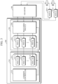
- the small cell signal source 200 of the cellular communication system in accordance with the exemplary aspect includes a first matching switch 250 and a common controller 213.
- the first matching switch 250 respectively matches lower protocol processors to the plurality of remote units 150 connected to the BIU by switching on or off an output path of each of the lower protocol processors.
- the common controller 213 activates a plurality of upper protocol processors of the upper small cell unit and a plurality of lower protocol processors of the lower small cell unit, and accordingly, controls an operation of the first matching switch 250.
- the upper protocol processors 211 may be implemented in a software manner, as well as in a circuitry manner.
- each of the upper protocol processors 211 may be programmed in a general programming language (e.g., C/C++ language, etc.), then be compiled and executed as a task or a process on a central processing unit (CPU).
- the lower protocol processors 231 may be implemented in a circuit manner.
- each of the lower protocol processors 231 may be implemented in the form of a gate array or firmware.
- a plurality of upper protocol processors 211-1 to 211-p of the upper small cell unit 210 may be implemented as software tasks whose execution is controlled by the common controller 213.
- a plurality of lower protocol processors 231-1 to 231-q of the lower small cell unit 230 may be implemented as software tasks whose execution is controlled by the common controller 213.
- the upper protocol processors 211-1 to 211-p are implemented as software tasks, they do not physically or logically reside within the upper small cell unit 210, and no corresponding program modules exist on a program code. Rather, the upper protocol processors may be considered as entities which are newly generated and executed on memory under the control of a scheduler.
- the small cell unit includes a plurality of upper protocol processors, such statement or similar expressions are intended to be construed to imply a case in which the plurality of upper protocol processors are implemented as software tasks, as well as a case in which the upper protocol processors are implemented physically, that is, as circuitry, in the upper small cell unit.
- some of logical modules of the upper protocol processor 211 may be implemented in a circuit manner.
- a part of each of the upper protocol processors 211 may be implemented in the form of a gate array or firmware, and the remaining part may be implemented as a software task.
- some of logical modules of the lower protocol processor 231 may be implemented in a circuit manner.
- a part of each of the lower protocol processor 231 may be implemented in the form of a gate array or firmware, and the remaining part may be implemented as a software task.
- the upper protocol processor 211 may be implemented as a software task, and the lower protocol processors 231-1 to 231-q may be implemented in a circuit manner.
- the common controller 213 schedules execution of shared resources of the upper small cell unit 210.
- the common controller 213 may be implemented as one of components included in the upper small cell unit.
- the small cell is an LTE small cell, and, for example, the common controller may be implemented as a function of a scheduler that processes scheduling of shared channel resources in the MAC layer.
- the common controller 213 operates to mitigate interference which may occur when a plurality of PHY layers transmit different RF signals using the same frequency in a multi-cell or multi-sector environment.
- the first matching switch 250 may be a physical switch that switches on or off output, or may be implemented as a software input/output interface for using an output of a program module as input or a program code, such as an input/output command.
- the first matching switch 250 is included in the lower small cell unit 230, but it is not limited thereto and may be configured as a separate device.
- the first matching switch 250 connects an output of each of the lower protocol processors 231 to a plurality of headend units 100 by switching on or off an output path of each of the lower protocol processors 231.
- the common controller 213 when the number of users increases in a region where a DAS provides services, that is, in a service region, the common controller 213 additionally activates the upper protocol processor 211 of the upper small cell unit.
- the common controller 213 when additional bandwidth or capacity is required due to an increase in the use of the frequency band by users in a region where the DAS provides services, i.e., in a service region, the common controller 213 additionally activates the lower protocol processor 231 of the lower small cell unit 230.
- the common controller 213 controls the first matching switch 250 to connect the activated lower protocol processor 231 to the remote unit that needs additional capacity.
- FIG. 4 is a block diagram illustrating a configuration of a cellular communication system according to another exemplary aspect.
- the cellular communication system includes a small cell signal source 200, a headend unit 100, and a plurality of remote units 150-1 and 150-2.
- the small cell signal source 200 includes an upper small cell unit 210, a lower small cell unit 230, and a second matching switch 250'.
- the upper small cell unit 210 includes a plurality of upper protocol processors 211-1 to 211-n that process an upper first part of a protocol stack of a small cell.
- the lower small cell unit 230 includes a plurality of lower protocol processors 231-1, 231-2, and 231-I that process a remaining second part of the protocol stack of the small cell.
- the second matching switch 250' switches on or off connections between each lower protocol processor of the lower small cell unit and each upper protocol processor of the upper small cell unit.
- the second matching switch 250' may be a physical switch that switches on or off output, or may be implemented as a software input/output interface for using an output of a program module as input, or a program code such as an input/output command. Since configurations corresponding to those of FIG. 4 are similar to those in FIG. 3 , detailed descriptions thereof are omitted.
- the common controller 213 when the number of users increases in a region where a DAS system provides services, i.e., in a service region, the common controller 213 additionally activates the upper protocol processor 211 of the upper small cell unit and the lower protocol processor 231 of the lower small cell unit, and in turn, controls an operation of the second matching switch 250'.
- the common controller 213 when additional bandwidth or capacity is required due to an increase in the use of the frequency band by users in a region where a DAS system provides services, i.e., in a service region, the common controller 213 additionally activates the lower protocol processor 231 of the lower small cell unit 230
- FIG. 5 is a block diagram illustrating a configuration of a cellular communication system according to still another exemplary aspect.
- the cellular communication system includes a small cell signal source 200, a headend unit 100, and a plurality of remote units 150-1 and 150-2.
- the small cell signal source 200 includes an upper small cell unit 210, a lower small cell unit 230, a first matching switch 250, and a second matching switch 250'.
- the upper small cell unit 210 includes a plurality of upper protocol processors 211-1 to 211-n that process an upper first part of a protocol stack of a small cell.
- the lower small cell unit 230 includes a plurality of lower protocol processors 231-1, 231-2, and 231-I that process a remaining second part of the protocol stack of the small cell.
- the first matching switch 250 switches on or off an output path of each lower protocol processor.
- the second matching switch 250' switches on or off a connection between each lower protocol processor of the lower small cell unit and each upper protocol processor of the upper small cell unit.
- Each of the first matching switch 250 and the second matching switch 250' may be a physical switch which switches on or off output, or may be implemented as a software input/output interface for using an output of a program module as input, or a program code such as an input/output command. Since configurations corresponding to those of FIG. 5 are similar to those in FIG. 3 , detailed descriptions thereof will be omitted.
- the common controller 213 when the number of users increases in a region where a DAS system provides services, that is, in a service region, the common controller 213 additionally activates the upper protocol processor 211 of the upper small cell unit and the lower protocol processor 231 of the lower small cell unit, and in turn, controls an operation of the second matching switch 250'.
- the common controller 213 when additional bandwidth or capacity is required due to an increase in the use of the frequency band by users in a region where a DAS system provides services, i.e., in a service region, the common controller 213 additionally activates the lower protocol processor 231 of the lower small cell unit 230, and in turn, controls an operation of the first matching switch 250.
- a plurality of lower protocol processors 231 may be connected to a single upper protocol processor 211.
- first matching switch 250 and the second matching switch 250' may be provided.
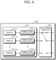
- FIG. 6 is a block diagram illustrating one aspect of a configuration of the lower small cell unit 230 in the exemplary aspect shown in FIG. 3 or 5 .
- the lower protocol processor 231 includes wireless converters 231'-1 to 231'-q.
- an output from the small cell is an RF signal
- the first matching switch 250 switches the RF signal from the lower protocol processor 231.
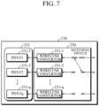
- FIG. 7 is a block diagram illustrating another aspect of a configuration of the lower small cell unit 230 in the exemplary aspect shown in FIG. 3 or 5 .
- the first matching switch includes wireless converters 251-1 to 251-q at a receiving side.
- the small cell outputs a digital signal, for example, an LTE IQ signal
- the first matching switch 250 converts the IQ signal into an RF signal by modulating the IQ signal in the receiving side, and then transmits the RF signal to the remote optical unit which matches the small cell.
- FIG. 8 is a block diagram illustrating still another aspect of a configuration of the lower small cell unit 230 in the exemplary aspect shown in FIG. 3 or 5 .
- the first matching switch 250 includes the wireless converters 251-1 to 251-q at an output side.
- the small cell outputs a digital signal, for example, an LTE IQ signal
- the first matching switch 250 respectively connects the small cells to the remote optical units so that outputs of the small cells respectively match the remote optical units, and then the first matching switch 250 converts the IQ signal into an RF signal by modulating the IQ signal, and outputs the RF signal.
- FIG. 9 is a block diagram illustrating one aspect of a configuration of the remote optical units 150-1 and 150-2 in the exemplary aspects shown in FIGs. 3 to 5 .
- the remote optical unit 150 includes three types of modules which are the photoelectric conversion unit 151 configured to convert optical RF signals received from ODUs 130 into electrical RF signals, the plurality of RDUs 156-1 and 156-2, and a combine unit 159 configured to combine signals generated from the RDUs.
- the remote optical unit 150 may include the plurality of RDUs 156-1 and 156-2.
- the RDUs may have different configurations from each other.
- the RDU 156-1 includes a bandpass filter 153-1 which filters only a required band in an RF signal on a downlink path, and a power amplifier 157-1 which amplifies the filtered RF signal.
- the RDU 156-1 includes a low noise amplifier 154-1 which amplifies a signal from an antenna on an uplink path.
- the RDU 156-2 includes a bandpass filter 153-2 which filters only a required band in the RF signal on the downlink path, and a power amplifier 157-2 which amplifies the filtered RF signal.
- the RDU 156-2 includes a low noise amplifier 154-2 which amplifies the signal from the antenna on the uplink path. Outputs from the two RDUs 156-1 and 156-2 are combined by the combine unit 159 and are transmitted to a single antenna.
- the bandpass filter 153-1 of the RDU 156-1 and the bandpass filter 153-2 of the RDU 156-2 may have different pass bands.
- a plurality of RF signals with different bands may be multiplexed and transmitted through a single optical fiber.
- the remote optical unit 150 may have a suitable configuration capable of transmitting RF signals of two different bands which are output from the headend unit 100.
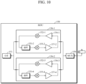
- FIG. 10 is a block diagram illustrating another aspect of a configuration of the remote optical units 150-1 and 150-2 in the exemplary aspects shown in FIGS. 3 to 5 .
- the remote optical unit 150 includes three types of modules which are the photoelectric conversion unit 151 configured to convert the optical RF signals received from the ODUs 130 into electrical RF signals, the plurality of RDUs 156-1 and 156-2, and the combine unit 159 configured to combine signals generated from the RDUs.
- the remote optical unit 150 may include the plurality of RDU modules 156-1 and 156-2.
- the RDUs may have different configurations from each other.
- the RDU 156-1 includes the bandpass filter 153-2 which filters only a required band in an RF signal on a downlink path, a demodulation unit 155-2 which demodulates the filtered RF signal by converting a band of the signal when necessary, and the power amplifier 157-2 which amplifies the demodulated signal.
- the RDU 156-1 includes the low noise amplifier 154-1 which amplifies a signal from an antenna on an uplink path, and a modulation unit 152-1 which modulates the amplified signal by converting a band of the signal when necessary.
- the RDU 156-2 includes a bandpass filter 153-4 which filters only a required band in the RF signal on the downlink path, a demodulation unit 155-4 which demodulates the filtered RF signal by converting a band of the signal when necessary, and a power amplifier 157-4 which amplifies the demodulated signal.
- the RDU 156-2 includes a low noise amplifier 154-3 which amplifies the signal from the antenna on the uplink path and a modulation unit 152-3 which modulates the amplified signal by converting a band of the signal when necessary.
- the modulated signal outputs from the two RDUs 156-1 and 156-2 are in different bands.
- the headend unit may modulate RF signals of the same bands and transmit the modulated signals in order to increase coverage or capacity. These RF signals of different bands are transmitted through different remote optical units. Outputs of the two RDUs 156-1 and 156-2 having different frequencies are combined by the combine unit 159 and are transmitted to a single antenna.
- FIG. 11 is a block diagram illustrating still another aspect of a configuration of the remote optical units 150-1 and 150-2 in the exemplary aspects shown in FIGS. 3 to 5 .
- the remote optical unit 150 includes three types of modules which are the photoelectric conversion unit 151 configured to convert the optical RF signals received from the ODUs 130 into electrical RF signals, the plurality of RDUs 156-1 and 156-2, and the combine unit 159 configured to combine signals generated from the RDUs.
- the remote optical unit 150 may include the plurality of RDU modules 156-1 and 156-2.
- the RDUs may have different configurations from each other.
- the RDU 156-1 includes the bandpass filter 153-1 which filters only a required band in an RF signal on a downlink path, and the power amplifier 157-1 which amplifies the filtered RF signal.
- the RDU 156-1 includes the low noise amplifier 154-1 which amplifies a signal from an antenna on an uplink path.
- the RDU 156-2 includes the bandpass filter 153-4 which filters only a required band in the RF signal on the downlink path, the demodulation unit 155-4 which demodulates the filtered RF signal by converting a band of the signal when necessary, and the power amplifier 157-4 which amplifies the demodulated signal.
- the RDU 156-2 includes the low noise amplifier 154-3 which amplifies the signal from the antenna on the uplink path, and the modulation unit 152-3 which modulates the amplified signal by converting a band of the signal when necessary.
- Outputs of the two RDUs 156-1 and 156-2 are combined by the combine unit 159 and are transmitted to a single antenna.
- the RDU 156-1 since the RDU 156-1 does not include a modulation/demodulation unit, the RDU 156-1 performs bandpass filtering on the RF signal output from the headend unit 100, then amplifies the filtered signal and outputs the amplified signal.
- the RDU 156-2 extracts an RF signal of a specific frequency band using the bandpass filter 153-4, demodulates the extracted RF signal through band-down conversion using the modulation/demodulation unit 155-4, and outputs a resulting signal.
- the common controller 213 may additionally activate the upper protocol processor 211 in the upper small cell unit 210, thereby increasing the number of users that can be supported.
- the common controller 213 may allocate more computational resources, for example, memory or CPU resources, to the upper protocol processor 211 being executed in the upper small cell unit 210, thereby enabling the increase of the number of users.
- the common controller 213 may additionally activate the lower protocol processor 231 being executed in the lower small cell unit 230, thereby increasing the bandwidth that can be supported.
- the common controller 213 may allocate more computational resources, for example, memory or CPU resources, to the lower protocol processor 231 being executed in the lower small cell unit 230, thereby enabling the increase of the bandwidth.
- the common controller 213 may need to appropriately control the first matching switch 250 or the second matching switch 250 in the lower small cell unit 230.
- FIG. 12 is a diagram for describing a first operation mode of a cellular communication system in accordance with the exemplary aspect shown in FIG. 3 .
- the first matching switch 250 distributes output from the lower protocol processor 231-1, i.e., a PHY layer 231-1, into two signals and transmits the two signals to two input ports, which are an RF_1_SISO port and an RF_1_MIMO port of the BIU 110.
- the BIU 110 includes two types of base-station signal driving units 111-1 and 111-2, one of which does not include a demodulator but has the RF_1_SISO input port, and the other of which includes a demodulator and has the RF_1_MIMO input port.
- both of the base-station signal driving units 111-1 and 111-2 may have the same configurations and may include demodulator modules therein, but the base-station signal driving unit 111-1 may be configured not to use the included demodulator module and the base-station signal driving unit 111-2 may be configured to use the included demodulator module.
- a band of a signal output from the base-station signal driving unit 111-1 is represented as RF_1_SISO
- a band of a signal output from the base-station signal driving unit 111-2 is represented as RF_1_MIMO.
- the common controller 213 has information about such a system configuration, and controls the first matching switch 250 according to the information so that interference among RF signals of the same frequency band can be avoided.
- the two base-station signal driving units 111-1 and 111-2 of the BIU 110 each receive the distributed RF signal.
- the base-station signal driving unit 111-1 which receives the RF signal through the RF_1_SISO input port, outputs the received RF signal intact to the combine-divider 113.
- the base-station signal driving unit 111-2 which receives the RF signal through the RF_1_MIMO input port, modulates the RF signal to up or down convert a band thereof, and outputs a resulting signal to the combine-divider 113.
- the combine-divider 113 mixes the two RF signals and outputs a mixture of the RF signals to the ODU 130.
- the reason why the base-station signal driving unit 111-2 modulates the RF signal is because otherwise the mixed signal output from the combine-divider 113 cannot be separated later.
- the ODU 130 converts the mixed signal into an optical RF signal and distributes the optical RF signal.
- the remote optical units 150-1 and 150-2 receive the distributed optical RF signal.
- the remote optical unit 150-1 has a suitable configuration capable of transmitting an RF signal of an RF_1_SISO band, which is output from the base-station signal driving unit 111-1 of the BIU 110.
- the remote optical unit 150-2 has a suitable configuration capable of transmitting an RF signal of an RF_1_MIMO band, which is output from the base-station signal driving unit 111-2 of the BIU 110.
- the remote optical unit 150-1 does not include a modulation/demodulation unit
- the remote optical unit 150-2 includes a modulation/demodulation unit to convert the RF signal of the RF_1_MIMO band into an RF signal of the RF_1_SISO band.
- the remote optical unit 150-1 photoelectrically converts the received optical RF signal into an electrical RF signal, then extracts an RF signal of a specified frequency band, i.e., the RF_1_SISO band, using the bandpass filter, amplifies the RF signal, and transmits the amplified signal to the antenna.
- the remote optical unit 150-2 photoelectrically converts the received optical RF signal into an electrical RF signal, then extracts an RF signal of another specified frequency band, i.e., the RF_1_MIMO band, using the bandpass filter, up or down converts a band of the extracted RF signal to a specified frequency band, amplifies the converted signal, and outputs a resulting signal to the antenna. Consequently, the two remote optical units 150-1 and 150-2 transmit the same data through RF signals of the same band. Since the two remote optical units 150-1 and 150-2 provide services to different floors of a building, coverage may be expanded.
- FIG. 13 is a diagram for describing a second operation mode of the cellular communication system in accordance with the exemplary aspect shown in FIG. 3 .
- the second operation mode described herein is an example of a response that the system in accordance with the proposed invention may make when it is necessary to increase the number of users and the bandwidth/capacity in the first operation mode illustrated in FIG. 12 .
- the common controller 213 controls an operation of the first matching switch and controls whether the headend unit performs modulation.
- the common controller 213 In the illustrated second operation mode, the common controller 213 generates and executes new tasks such that the common controller 213 generates and executes a new upper protocol processor 211-2 and a new lower protocol processor 231-2 and connects both of the processors.
- MAC+#2 processes different data as the new upper protocol processor 211-2 from data processed by MAC+#1.
- the new lower protocol processor 231-2 outputs a signal of the same frequency band as that of the existing lower protocol processor 231-1.
- the first matching switch 250 disconnects the existing connection between the lower protocol processor PHY#1 231-1 and the RF_1_MIMO input port of the base-station signal driving unit 111-2, and connects the newly generated and executed lower protocol processor PHY#2 231-2 to the RF_1_MIMO input port of the base-station signal driving unit 111-2.
- the two upper protocol processors 211-1 and 211-2 and the two lower protocol processors 231-1 and 231-2 are executed, which is generally identical to the case of two small cells being executed.
- the two base-station signal driving units 111-1 and 111-2 of the BIU 110 receive RF signals through two input ports.
- the base-station signal driving unit 111-1 outputs the received RF signal intact to the combine-divider 113.
- the base-station signal driving unit 111-2 modulates the received RF signal to up or down convert a band thereof, and outputs a resulting signal to the combine-divider 113.
- the reason why the base-station signal driving unit 111-2 modulates the RF signal is because otherwise the mixed signal output from the combine-divider 113 cannot be separated later.
- the ODU 130 converts the mixed signal into an optical RF signal and distributes the optical RF signal.
- the remote optical units 150-1 and 150-2 receive the distributed optical RF signal.
- the remote optical unit 150-1 photoelectrically converts the received optical RF signal into an electrical RF signal, then extracts an RF signal of a specified frequency band, i.e., the RF_1_SISO band, using the bandpass filter, amplifies the RF signal, and transmits the amplified signal to the antenna.
- a specified frequency band i.e., the RF_1_SISO band
- the remote optical unit 150-2 photoelectrically converts the received optical RF signal into an electrical RF signal, then extracts an RF signal of another specified frequency band, i.e., the RF_1_MIMO band, using the bandpass filter, up or down converts a band of the extracted RF signal to a specified frequency band, amplifies a converted signal, and outputs a resulting signal to the antenna. Consequently, since the two remote optical units 150-1 and 150-2 transmit different LTE data through RF signals of the same band, it is possible to form two mobile communication cells and to double the number of users and the bandwidth/capacity in comparison to the first operation mode illustrated in FIG. 12 .
- FIG. 14 is a diagram for describing a third operation mode of the cellular communication system in accordance with the exemplary aspect shown in FIG. 4 or 5 .
- the third operation mode described herein is an example of a response that the system in accordance with the proposed invention may make when a necessity to increase bandwidth/capacity used by users arises in the first operation mode illustrated in FIG. 12 .
- the common controller 213 when it is necessary to increase bandwidth/capacity, the common controller 213 additionally activates the lower protocol processor, controls an operation of the first matching switch, and controls whether the lower protocol processor performs modulation. In the illustrated third operation mode, the common controller 213 generates and executes new tasks such that the common controller 213 generates and executes a new lower protocol processor 231-2. The common controller 213 controls the second matching switch 250' to connect the newly generated lower protocol processor 231-2 to the upper protocol processor 211-1.
- the new lower protocol processor 231-2 outputs a signal of the same frequency band as that of the existing lower protocol processor 231-1.
- the first matching switch 250 disconnects the existing connection between the lower protocol processor PHY#1 231-1 and the RF_1_MIMO input port of the base-station signal driving unit 111-2, and connects the newly generated and executed lower protocol processor PHY#2 231-2 to the RF_1_MIMO input port of the base-station signal driving unit 111-2.
- the base-station signal driving units 111-1 and 111-2 of the BIU 110 receive RF signals through two input ports.
- the base-station signal driving unit 111-1 outputs the received RF signal intact to the combine-divider 113.
- the base-station signal driving unit 111-2 modulates the received RF signal to up or down convert a band thereof, and outputs a resulting signal to the combine-divider 113.
- the reason why the base-station signal driving unit 111-2 modulates the RF signal is because otherwise the mixed signal output from the combine-divider 113 cannot be separated later.
- the ODU 130 converts the mixed signal into an optical RF signal and distributes the optical RF signal.
- the remote optical units 150-1 and 150-2 receive the distributed optical RF signal.
- the remote optical unit 150-1 photoelectrically converts the received optical RF signal into an electrical RF signal, then extracts an RF signal of a specified frequency band, i.e., the RF_1_SISO band, using the bandpass filter, amplifies the RF signal, and transmits the amplified signal to the antenna.
- a specified frequency band i.e., the RF_1_SISO band
- the remote optical unit 150-2 photoelectrically converts the received optical RF signal into an electrical RF signal, then extracts an RF signal of another specified frequency band, i.e., the RF_1_MIMO band, using the bandpass filter, up or down converts a band of the extracted RF signal to a specified frequency band, amplifies the converted signal, and outputs a resulting signal to the antenna. Consequently, the bandwidths of both the remote optical units 150-1 and 150-2 can be widened more than that of the first operation mode of FIG. 12 .
- FIG. 15 is a diagram illustrating an example of another cellular communication system that implements the second operation mode described with reference to FIG. 13 .
- the example shown in FIG. 15 is substantially the same as the exemplary aspect of FIG. 13 , but the base-station signal driving unit 111-2 and the corresponding remote unit 150-2 do not need a modulation/demodulation unit. Rather, the lower protocol processors of the lower baseband unit 230 are connected with the wireless converters 231'-1 and 231'-2, respectively.
- the respective lower protocol processors of the exemplary aspects illustrated in FIGS. 12 to 14 require wireless converters, which are simply omitted in the drawings.
- the difference between the above aspects and the present aspect is that modulation/demodulation frequencies of the wireless converters are controlled by the common controller 213.
- Mobile communication service operators use multiple frequencies for the same service in order to support as much bandwidth and/or as many users as possible.
- Terminal devices search all of multiple frequencies for services of the same service operator.
- the common controller 213 controls modulation/demodulation frequencies of the wireless converters in order to increase the number of users and/or the bandwidth.
- the upper protocol processor 211-1 and the lower protocol processor 231-2 are additionally activated for the same service operator, and the wireless converter 231'-1 and the wireless converter 231'-2 are controlled to select two of the multiple frequencies used by the service operator and modulate/demodulate the selected frequencies.
- the bandpass filter 153-1 of the remote unit 150-1 is tuned to a band of the wireless converter 231'-1
- the bandpass filter 153-2 of the remote unit 150-2 is tuned to a band of the wireless converter 231'-2.
- the coverage as well as the bandwidth and the number of users can be substantially increased for the same service operator.
- FIG. 15 employs the configuration illustrated in FIG. 6 , it should be understood by those skilled in the art that the configuration of FIG. 7 or 8 can be applied to FIG. 13 through the exemplary aspect of FIG. 15 .
- FIG. 16 is a diagram for describing a fifth operation mode of the cellular communication system in accordance with the exemplary aspect illustrated in FIG. 3 or 5 .
- the fifth operation mode may be initiated.
- the fifth operation mode may be initiated in order to increase the throughput in the second operation mode illustrated in FIG. 13 .
- the common controller 213 In the fifth operation mode, the common controller 213 generates and executes the additional upper protocol processor 211-2 in the upper small cell unit 210, generates and executes the additional lower protocol processor 231-2 in the lower small cell unit 230, and connects the upper protocol processor 211-2 and the lower protocol processor 231-2.
- PHY#1 and PHY#2 are hardware circuits, the common controller 213 transmits only an output of the newly executed upper protocol processor 211-2 to PHY#2.
- MAC+#1 which is the existing upper protocol processor 211-1, outputs data D1, while MAC+#2, which is the newly executed upper protocol processor 211-2, outputs data D2.
- PHY#1 which is the existing lower protocol processor 231-1, transmits a signal of an RF_1 band, while PHY#2, which is the newly executed lower protocol processor 231-2, outputs a signal of an RF_2 band.
- the first matching switch 250 distributes each output of each lower protocol processor 231-1 and 231-2, i.e., PHY#1 and PHY#2 231-1 and 231-2, into two, and transmits the distributed output to one pair of the RF_1_SISO port and the RF_1_MIMO port and the other pair of an RF_2_SISO port and an RF_2_MIMO port, which are pairs of input ports of the BIU 110.
- the BIU 110 includes two activated base-station signal driving units 111-1 and 111-4 that receive RF signals of the RF_1 band as an input such that one base-station signal driving unit does not include a modulator but has the RF_1_SISO input port while the other includes a modulator and has the RF_1_MIMO input port.
- a band of the signal output from the base-station signal driving unit 111-1 is represented as RF_1_SISO
- a band of the signal output from the base-station signal driving unit 111-4 is represented as RF_1_MIMO.
- the BIU 110 includes two activated base-station signal driving units 111-2 and 111-3 that receive RF signals of the RF_2 band as inputs such that one base-station signal driving unit does not include a modulator but has the RF_2_SISO input port while the other includes a modulator and has the RF_2_MIMO input port.
- a band of the signal output the base-station signal driving unit 111-2 is represented as RF_2_SISO
- a band of the signal output from the base-station signal driving unit 111-3 is represented as RF_2_MIMO.
- the common controller 213 has information about such a system configuration, and controls the first matching switch 250 according to the information so that interference among RF signals of the same frequency band can be avoided.
- the two base-station signal driving units 111-1 and 111-4 of the BIU 110 each receive the distributed RF signal.
- the base-station signal driving unit 111-1 which receives the RF signal through the RF_1_SISO input port, outputs the received RF signal intact to the combine-divider 113.
- the base-station signal driving unit 111-4 which receives the RF signal through the RF_1_MIMO input port, modulates the RF signal to up or down convert a band thereof, and outputs a resulting signal to the combine-divider 113.
- the two base-station signal driving unit 111-2 and 111-3 of the BIU 110 each receive the distributed RF signal.
- the base-station signal driving unit 111-2 which receives the RF signal through the RF_2_SISO input port, outputs the received RF signal intact to the combine-divider 113.
- the base-station signal driving unit 111-3 which receives the RF signal through the RF_2_MIMO input port, modulates the RF signal to up or down convert a band thereof, and outputs a resulting signal to the combine-divider 113.
- the combine-divider 113 mixes the four signals and outputs a mixture of the signals to the ODU 130.
- the ODU 130 converts the mixed signal into an optical RF signal and distributes the optical RF signal.
- the remote optical units 150-1 and 150-2 receive the distributed optical RF signal.
- the remote optical unit 150-1 may be configured as the exemplary aspect of FIG. 9 and the remote optical unit 150-2 may be configured as the exemplary aspect of FIG. 10 .
- the operations of the remote optical units 150-1 and 150-2 in accordance with the exemplary aspect of FIG. 18 will be described with reference to FIGS. 9 and 10 .
- the remote optical unit 150-1 processes signals of two channels and has a configuration suitable to transmit RF signals of two bands, i.e., the RF_1_SISO band and the RF_2_SISO band, which are output from the base-station signal driving units 111-1 and 111-2 of the BIU 110.
- An upper channel of the remote optical unit 150-1 extracts an RF signal of a specified frequency band, i.e., the RF_1_SISO band, from a photoelectrically converted RF signal output from the photoelectric conversion unit (151) through the bandpass filter 153-1, amplifies the extracted RF signal, and outputs a resulting signal to the antenna.
- a lower channel of the remote optical unit 150-1 extracts an RF signal of a specified frequency band, i.e., the RF_2_SISO band, from the photoelectrically converted RF signal output from the photoelectric conversion unit (151) through the bandpass filter 153-2, amplifies the extracted RF signal, and outputs a resulting signal to the antenna.
- the RF signal of RF_1_SISO band and the RF signal of RF_2_SISO band are mixed in a forward direction by the combine unit 159 and then transmitted to the antenna. Descriptions of an uplink will be omitted.
- the remote optical unit 150-2 processes signals of two channels and has a configuration suitable to transmit RF signals of two bands, i.e., the RF_1_MIMO band and the RF_2_MIMO band, which are output from the base-station signal driving units 111-3 and 111-4 of the BIU 110.
- the remote optical unit 150-1 does not include a modulation/demodulation unit
- the remote optical unit 150-2 includes the modulation/demodulation unit 155-2, which converts the RF signal of the RF_1_MIMO band into an RF signal of the RF_1 band
- the modulation/demodulation unit 155-4 which converts the RF signal of the RF_2_MIMO band into an RF signal of the RF_2 band.
- An upper channel of the remote optical unit 150-2 extracts an RF signal of another specified frequency band, i.e., the RF_1_MIMO band, from a photoelectrically converted RF signal output from the photoelectric conversion unit (151) through the bandpass filter 153-2, demodulates the extracted RF signal to a specified frequency band, i.e., the RF_1 band, through band-down conversion by the modulation/demodulation unit 155-2, amplifies the demodulated RF signal in the amplifier 157-2, and outputs a resulting signal to the antenna.
- a specified frequency band i.e., the RF_1_MIMO band
- a lower channel of the remote optical unit 150-2 extracts an RF signal of another frequency band, i.e., the RF_2_MIMO band, from the photoelectrically converted RF signal through the bandpass filter 153-4, demodulates the extracted RF signal to a specified frequency band, i.e., the RF_2 band, through band-down conversion by the modulation/demodulation unit 155-4, amplifies the demodulated RF signal in the amplifier 157-4, and outputs a resulting signal to the antenna.
- the RF signal of the RF_1_MIMO band and the RF signal of the RF_2_MIMO band are mixed in the forward direction by the combine unit 159 and then transmitted to the antenna. Descriptions of an uplink will be omitted.
- both of the remote optical units 150-1 and 150-2 transmit the data D1 through the RF signal of the RF_1 band and the data D2 through the RF signal of the RF_2 band. That is, since different data D1 and D2 are transmitted using two frequency bands RF_1 and RF_2, it is the same as functions of two cells or a single cell sectorized into two sectors.
- FIG. 17 is a diagram for describing a sixth operation mode of the cellular communication system in accordance with the exemplary aspect illustrated in FIG. 3 or 5 .
- the sixth operation mode may be initiated.
- the common controller 213 In the sixth operation mode, the common controller 213 generates and executes another additional upper protocol processor 211-3 in the upper small cell unit 210, generates and executes another additional lower protocol processor 231-3 in the lower small cell unit 230, and connects the upper protocol processor 211-3 and the lower protocol processor 231-3.
- PHY#1, PHY#2, and PHY#3 are hardware circuits, the common controller 213 transmits only an output of the newly executed upper protocol processor 211-3 to PHY#3.
- MAC+#1 and MAC+#2 which are the existing upper protocol processors 211-1 and 211-2, output data D1 and data D2, respectively, while MAC+#3, which is the newly executed upper protocol processor 211-3, outputs data D3.
- PHY#1 which is the existing lower protocol processor 231-1, transmits a signal of the RF_1 band
- PHY#3, which is the newly executed lower protocol processor 231-3 outputs a signal of the RF_2 band as does the existing lower protocol processor 213-2.
- the first matching switch 250 distributes an output of the lower protocol processor 231-1, i.e., PHY#1, into two signals, and transmits the distributed output to the RF_1_SISO port and the RF_1_MIMO port, which are input ports of the BIU 110. Also, the first matching switch 250 connects output of the lower protocol processor 231-2, i.e., PHY#2, with the RF_2_SISO port, which is an input port of the BIU 110.
- the first matching switch 250 disconnects the existing connection between the lower protocol processor 231-2, i.e., PHY#2, and the RF_2_MIMO input port of the BIU 110, and connects the newly generated and executed lower protocol processor 231-3, i.e., PHY#2 231-2, with the RF_2_MIMO input port of the BIU 110.
- the BIU 110 includes two activated base-station signal driving units 111-1 and 111-4 that receive RF signals of the RF_1 band as an input such that one base-station signal driving unit does not include a modulator but has the RF_1_SISO input port while the other includes a modulator and has the RF_1_MIMO input port.
- a band of the signal output from the base-station signal driving unit 111-1 is represented as RF_1_SISO
- a band of the signal output from the base-station signal driving unit 111-4 is represented as RF_1_MIMO.
- the BIU 110 includes two activated base-station signal driving units 111-2 and 111-3 that receive RF signals of the RF_2 band as an input such that one base-station signal driving unit does not include a modulator/demodulator but has the RF_2_SISO input port while the other includes a modulator/demodulator and has the RF_2_MIMO input port.
- a band of the signal output from the base-station signal driving unit 111-2 is represented as RF_2_SISO
- a band of the signal output from the base-station signal driving unit 111-3 is represented as RF_2_MIMO.
- the common controller 213 has information about such a system configuration, and controls the first matching switch 250 according to the information so that interference among RF signals of the same frequency band can be avoided.
- the two base-station signal driving unit 111-1 and 111-4 of the BIU 110 each receive the distributed RF signal.
- the base-station signal driving unit 111-1 which receives the RF signal through the RF_1_SISO input port, outputs the received RF signal intact to the combine-divider 113.
- the base-station signal driving unit 111-4 which receives the RF signal through the RF_1_MIMO input port, modulates the RF signal to up or down convert a band thereof, and outputs a resulting signal to the combine-divider 113.
- the two base-station signal driving unit 111-2 and 111-3 of the BIU 110 receive the RF signal from PHY#2 and PHY#3, respectively.
- the base-station signal driving unit 111-2 which receives the RF signal through the RF_2_SISO input port, outputs the received RF signal intact to the combine-divider 113.
- the base-station signal driving unit 111-3 which receives the RF signal through the RF_2_MIMO input port, modulates the RF signal to up or down convert a band thereof, and outputs a resulting signal to the combine-divider 113.
- the combine-divider 113 mixes the four signals and outputs a mixture of the signals to the ODU 130.
- the ODU 130 converts the mixed signal into an optical RF signal and distributes the optical RF signal.
- the remote optical unit 150-1 may be configured as the exemplary aspect of FIG. 9 and the remote optical unit 150-2 may be configured as the exemplary aspect of FIG. 10 .
- the operations of the remote optical units 150-1 and 150-2 in accordance with the exemplary aspect of FIG. 18 will be described with reference to FIGS. 9 and 10 .
- the remote optical unit 150-1 processes signals of two channels and has a suitable configuration capable of transmitting RF signals of two bands, i.e., the RF_1_SISO band and the RF_2_SISO band, which are output from the base-station signal driving units 111-1 and 111-2 of the BIU 110.
- An upper channel of the remote optical unit 150-1 extracts an RF signal of a specified frequency band, i.e., the RF_1_SISO band, from a photoelectrically converted RF signal output from the photoelectric conversion unit (151) through the bandpass filter 153-1, amplifies the extracted RF signal, and outputs a resulting signal to the antenna.
- a lower channel of the remote optical unit 150-1 extracts an RF signal of a specified frequency band, i.e., the RF_2_SISO band, from the photoelectrically converted RF signal output from the photoelectric conversion unit (151) through the bandpass filter 153-2, amplifies the extracted RF signal, and outputs a resulting signal to the antenna.
- the RF signal of RF_1_SISO band and the RF signal of RF_2_SISO band are mixed in the forward direction by the combine unit 159 and then transmitted to the antenna. Descriptions of an uplink will be omitted.
- the remote optical unit 150-2 processes signals of two channels and has a suitable configuration capable of transmitting RF signals of two bands, i.e., the RF_1_MIMO band and the RF_2_MIMO band, which are output from the base-station signal driving units 111-3 and 111-4 of the BIU 110.
- the remote optical unit 150-1 does not include a modulation/demodulation unit
- the remote optical unit 150-2 includes the modulation/demodulation unit 155-2, which converts the RF signal of the RF_1_MIMO band into an RF signal of the RF_1 band
- the modulation/demodulation unit 155-4 which converts the RF signal of the RF_2_MIMO band into an RF signal of the RF_2 band.
- An upper channel of the remote optical unit 150-2 extracts an RF signal of another specified frequency band, i.e., the RF_1_MIMO band, from a photoelectrically converted RF signal output from the photoelectric conversion unit (151) through the bandpass filter 153-2, demodulates the extracted RF signal to a specified frequency band, i.e., the RF_1 band through band-down conversion by the modulation/demodulation unit 155-2, amplifies the demodulated RF signal in the amplifier 157-2, and outputs a resulting signal to the antenna.
- a specified frequency band i.e., the RF_1_MIMO band
- a lower channel of the remote optical unit 150-2 extracts an RF signal of another frequency band, i.e., the RF_2_MIMO band, from the photoelectrically converted RF signal through the bandpass filter 153-4, demodulates the extracted RF signal to a specified frequency band, i.e., the RF_2 band through band-down conversion by the modulation/demodulation unit 155-4, amplifies a demodulated RF signal in the amplifier 157-4, and outputs a resulting signal to the antenna.
- the RF signal of RF_1_MIMO band and the RF signal of RF_2_MIMO band are mixed in the forward direction by the combine unit 159 and then transmitted to the antenna. Descriptions of an uplink will be omitted.
- the remote optical unit 150-1 transmits the data D1 through the RF signals of the RF_1 band and the data D2 through the RF signals of the RF_2 band
- the remote optical unit 150-2 transmits the data D1 through the RF signals of the RF_1 band and the data D3 through the RF signals of the RF_2 band. That is, since different data D1, D2, and D3 are transmitted using two frequency bands RF_1 and RF_2, it is the same as functions of three cells or a single cell sectorized into three sectors.
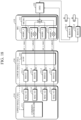
- FIG. 18 is a diagram for describing a seventh operation mode of the cellular communication system in accordance with the exemplary aspect illustrated in FIG. 3 or 5 .
- the seventh operation mode may be initiated.
- the common controller 213 In the seventh operation mode, the common controller 213 generates and executes another additional upper protocol processor 211-4 in the upper small cell unit 210, generates and executes another additional lower protocol processor 231-4 in the lower small cell unit 230, and connects the upper protocol processor 211-4 and the lower protocol processor 231-4.
- PHY#1, PHY#2, PHY#3, and PHY#4 are hardware circuits, the common controller 213 transmits only an output of the newly executed upper protocol processor 211-4 to PHY#4.
- MAC+#1, MAC+#2, and MAC+#3, which are the existing upper protocol processors 211-1, 211-2, and 211-3, output data D1, data D2, and data D3, respectively, while MAC+#4, which is the newly executed upper protocol processor 211-4, outputs data D4.
- the first matching switch 250 disconnects the existing connection between the lower protocol processor 231-1, i.e., PHY#1 231-1, and the RF_1_MIMO input port of the BIU 110, and connects the newly executed lower protocol processor 231-4, i.e., PHY#4 231-4, with the RF_1_MIMO input port of the BIU 110. Connections of the remaining two input ports are maintained in the same state as the sixth operation mode.
- the configurations of the BIU 110 and the remote optical units 150-1 and 150-2 are similar to those in the sixth operation mode.
- the common controller 213 has information about such a system configuration, and controls the first matching switch 250 according to the information so that interference among RF signals of the same frequency band can be avoided.
- the four base-station signal driving units 111-1, 111-2, 111-3, and 111-4 of the BIU 110 receive an RF_1_SISO RF signal, an RF_2_SISO RF signal, an RF_2_MIMO RF signal, and an RF_1_MIMO RF signal, respectively.
- the base-station signal driving unit 111-1 which receives the RF signal through the RF_1_SISO input port, outputs the RF signal intact to the combine-divider 113.
- the base-station signal driving unit 111-2 which receives the RF signal through the RF_2_SISO input port, outputs the RF signal intact to the combine-divider 113.
- the base-station signal driving unit 111-3 which receives the RF signal through the RF_2_MIMO input port, modulates the received RF signal to up or down convert a band thereof and outputs a resulting signal to the combine-divider 113.
- the base-station signal driving unit 111-4 which receives the RF signal through the RF_1_MIMO input port, modulates the RF signal to up or down convert a band thereof and outputs a resulting signal to the combine-divider 113.
- the combine-divider 113 mixes the four signals and outputs a mixture of the signals to the ODU 130.
- the ODU 130 converts the mixed signal into an optical RF signal and distributes the optical RF signal.
- the remote optical unit 150-1 may be configured as the exemplary aspect of FIG. 9 and the remote optical unit 150-2 may be configured as the exemplary aspect of FIG. 10 .
- the operations of the remote optical units 150-1 and 150-2 in accordance with the exemplary aspect of FIG. 18 will be described with reference to FIGS. 9 and 10 .
- the remote optical unit 150-1 processes signals of two channels and has a suitable configuration capable of transmitting RF signals of two bands, i.e., the RF_1_SISO band and the RF_2_SISO band, which are output from the base-station signal driving units 111-1 and 111-2 of the BIU 110.
- An upper channel of the remote optical unit 150-1 extracts an RF signal of a specified frequency band, i.e., the RF_1_SISO band, from a photoelectrically converted RF signal output from the photoelectric conversion unit (151) through the bandpass filter 153-1, amplifies the extracted RF signal, and outputs a resulting signal to the antenna.
- a lower channel of the remote optical unit 150-1 extracts an RF signal of a specified frequency band, i.e., the RF_2_SISO band, from the photoelectrically converted RF signal output from the photoelectric conversion unit (151) through the bandpass filter 153-2, amplifies the extracted RF signal, and outputs a resulting signal to the antenna.
- the RF signal of the RF_1_SISO band and the RF signal of the RF_2_SISO band are mixed in the forward direction by the combine unit 159 and then transmitted to the antenna. Descriptions of an uplink will be omitted.
- the remote optical unit 150-2 processes signals of two channels and has a suitable configuration capable of transmitting RF signals of two bands, i.e., the RF_1_MIMO band and the RF_2_MIMO band, which are output from the base-station signal driving units 111-3 and 111-4 of the BIU 110.
- the remote optical unit 150-1 does not include a modulation/demodulation unit
- the remote optical unit 150-2 includes the modulation/demodulation unit 155-2, which converts the RF signal of the RF_1_MIMO band into an RF signal of the RF_1 band
- the modulation/demodulation unit 155-4 which converts the RF signal of the RF_2_MIMO band into an RF signal of the RF_2 band.
- An upper channel of the remote optical unit 150-2 extracts an RF signal of another specified frequency band, i.e., the RF_1_MIMO band, from a photoelectrically converted RF signal output from the photoelectric conversion unit (151) through the bandpass filter 153-2, demodulates the extracted RF signal to a specified frequency band, i.e., the RF_1 band through band-down conversion by the modulation/demodulation unit 155-2, amplifies the demodulated RF signal in the amplifier 157-2, and outputs a resulting signal to the antenna.
- a specified frequency band i.e., the RF_1_MIMO band
- a lower channel of the remote optical unit 150-2 extracts an RF signal of another frequency band, i.e., the RF_2_MIMO band, from the photoelectrically converted RF signal through the bandpass filter 153-4, demodulates the extracted RF signal to a specified frequency band, i.e., the RF_2 band through band-down conversion by the modulation/demodulation unit 155-4, amplifies the demodulated RF signal in the amplifier 157-4, and outputs a resulting signal to the antenna.
- the RF signal of RF_1_MIMO band and the RF signal of RF_2_MIMO band are mixed in the forward direction by the combine unit 159 and then transmitted to the antenna. Descriptions of an uplink will be omitted.
- the remote optical unit 150-1 transmits the data D1 through the RF signals of the RF_1 band and the data D2 through the RF signals of the RF_2 band, while the remote optical unit 150-2 transmits the data D4 through the RF signals of the RF_1 band and the data D3 through the RF signals of the RF_2 band. That is, since different data D1, D2, D3, and D4 are sent out using two frequency bands RF_1 and RF_2, it is the same as functions of four cells or a single cell sectorized into four sectors.
- a band of the RF signal output from the first matching switch 250 of the lower small cell unit 230 matches a frequency of the bandpass filter of the RDU in the matched remote optical unit.
- the band of the RF signal is converted in the base-station signal driving unit 111 of the BIU 110, the band matches the frequency of the bandpass filter of the RDU inside the matched remote optical unit.
- the common controller additionally activates and allocates another physical layer, or controls the base-station signal driving unit to up or down convert a band of the signal to a band of the bandpass filter of a remote unit to be connected thereto in order to increase throughput for a physical layer that uses the same frequency band, and thereby an increase in throughput is generally achieved.
Landscapes
- Engineering & Computer Science (AREA)
- Computer Networks & Wireless Communication (AREA)
- Signal Processing (AREA)
- Mobile Radio Communication Systems (AREA)
Claims (11)
- Eine Kleinzellensignalquelle (200) zur Verwendung in einem zellularen Kommunikationssystem, wobei die Kleinzellensignalquelle (200) Folgendes umfasst:eine obere Kleinzelleneinheit (210), die eine Vielzahl von oberen Protokollprozessoren (211) umfasst, die so konfiguriert sind, dass sie einen oberen ersten Teil eines Protokollstapels einer Kleinzelle verarbeiten,eine untere Kleinzelleneinheit (230), die eine Vielzahl von unteren Protokollprozessoren (231) umfasst, die so konfiguriert sind, dass sie einen verbleibenden zweiten Teil des Protokollstapels der Kleinzelle verarbeiten,einen ersten Anpassungsschalter (250), der so konfiguriert ist, dass er einen Ausgabepfad jedes der unteren Protokollprozessoren (231) ein- oder ausschaltet,eine gemeinsame Steuerung (213), die so konfiguriert ist, dass sie die Aktivierung der Vielzahl von oberen Protokollprozessoren (211) der oberen Kleinzelleneinheit (210) und der Vielzahl von unteren Protokollprozessoren (231) der unteren Kleinzelleneinheit (230) gemäß einer erforderlichen Dienstkapazität steuert, und so konfiguriert ist, dass diese einen Betrieb des ersten Anpassungsschalters (250) und des zweiten Anpassungsschalters (250') steuert, gekennzeichnet durchein zweiter Anpassungsschalter (250'), der so konfiguriert ist, dass er Verbindungen zwischen jedem unteren Protokollprozessor der unteren Kleinzelleneinheit und jedem oberen Protokollprozessor der oberen Kleinzelleneinheit ein- oder ausschaltet, und wobei die gemeinsame Steuerung so konfiguriert ist, dass sie den Betrieb des zweiten Anpassungsschalters steuert.
- Die Kleinzellensignalquelle (200) nach Anspruch 1, wobei die oberen Protokollprozessoren (211) so konfiguriert sind, dass sie eine Medienzugriffssteuerung (MAC) oder eine höhere Schicht im Protokollstapel der Kleinzelle verarbeiten, und die unteren Protokollprozessoren (231) so konfiguriert sind, dass sie eine physikalische Schicht (PHY) im Protokollstapel der Kleinzelle verarbeiten.
- Die Kleinzellensignalquelle (200) nach Anspruch 1, wobei die Vielzahl der oberen Protokollprozessoren (211) der oberen Kleinzelleneinheit als Software-Tasks implementiert sind, deren Ausführung durch die gemeinsame Steuerung (213) gesteuert wird.
- Die Kleinzellensignalquelle (200) nach Anspruch 1, wobei die Vielzahl von unteren Protokollprozessoren (231) der unteren Kleinzelleneinheit als Software-Tasks implementiert sind, deren Ausführung durch die gemeinsame Steuerung (213) gesteuert wird.
- Die Kleinzellensignalquelle (200) nach Anspruch 1, wobei die gemeinsam Steuerung durch einen in der oberen Kleinzelleneinheit enthaltenen Teil implementiert ist.
- Die Kleinzellensignalquelle (200) nach Anspruch 1, wobei die gemeinsame Steuerung (213) so konfiguriert ist, dass sie zusätzlich die oberen Protokollprozessoren (211) aktiviert, wenn eine Erhöhung der Anzahl von Benutzern erforderlich ist.
- Die Kleinzellensignalquelle (200) nach Anspruch 1, wobei die gemeinsame Steuerung (213) so konfiguriert ist, dass sie zusätzlich den unteren Protokollprozessor (231) aktiviert, wenn eine Erhöhung der Bandbreite erforderlich ist, und dementsprechend die gemeinsame Steuerung (213) so konfiguriert ist, dass sie den Betrieb des ersten Anpassungsschalters (250) steuert.
- Die Kleinzellensignalquelle (200) nach Anspruch 1, die ferner eine Vielzahl von drahtlosen Wandlern umfasst, die jeweils zwischen den unteren Protokollprozessoren (231) und den Eingangsanschlüssen des ersten Anpassungsschalters (250) angeordnet sind und so konfiguriert sind, dass sie eine Ausgabe des unteren Protokollprozessors (231) in ein Hochfrequenzsignal (HF) umwandeln.
- Die Kleinzellensignalquelle (200) nach Anspruch 8, wobei die gemeinsame Steuerung (250) die Vielzahl von drahtlosen Wandlern mit demselben Dienstprozess steuert, so dass verschiedene Frequenzen moduliert werden.
- Die Kleinzellensignalquelle (200) nach Anspruch 1, die ferner eine Vielzahl von drahtlosen Wandlern umfasst, die jeweils mit Ausgangsanschlüssen des ersten Anpassungsschalters (250) verbunden sind und so konfiguriert sind, dass sie eine Ausgabe jedes der unteren Protokollprozessoren (231) in ein HF-Signal umwandeln.
- Die Kleinzellensignalquelle (200) nach Anspruch 10, wobei die gemeinsame Steuerung (250) die Vielzahl von drahtlosen Wandlern mit demselben Dienstprozess steuert, so dass unterschiedliche Frequenzen moduliert werden.
Priority Applications (1)
| Application Number | Priority Date | Filing Date | Title |
|---|---|---|---|
| EP20207584.2A EP3836744B1 (de) | 2018-01-25 | 2018-01-25 | Zellulares kommunikationssystem |
Applications Claiming Priority (2)
| Application Number | Priority Date | Filing Date | Title |
|---|---|---|---|
| EP20207584.2A EP3836744B1 (de) | 2018-01-25 | 2018-01-25 | Zellulares kommunikationssystem |
| EP18153383.7A EP3518615B1 (de) | 2018-01-25 | 2018-01-25 | Zellulares kommunikationssystem |
Related Parent Applications (2)
| Application Number | Title | Priority Date | Filing Date |
|---|---|---|---|
| EPPCT/EP2018/153383 Previously-Filed-Application | 2018-01-25 | ||
| EP18153383.7A Division EP3518615B1 (de) | 2018-01-25 | 2018-01-25 | Zellulares kommunikationssystem |
Publications (3)
| Publication Number | Publication Date |
|---|---|
| EP3836744A1 EP3836744A1 (de) | 2021-06-16 |
| EP3836744C0 EP3836744C0 (de) | 2025-03-05 |
| EP3836744B1 true EP3836744B1 (de) | 2025-03-05 |
Family
ID=61156989
Family Applications (2)
| Application Number | Title | Priority Date | Filing Date |
|---|---|---|---|
| EP20207584.2A Active EP3836744B1 (de) | 2018-01-25 | 2018-01-25 | Zellulares kommunikationssystem |
| EP18153383.7A Active EP3518615B1 (de) | 2018-01-25 | 2018-01-25 | Zellulares kommunikationssystem |
Family Applications After (1)
| Application Number | Title | Priority Date | Filing Date |
|---|---|---|---|
| EP18153383.7A Active EP3518615B1 (de) | 2018-01-25 | 2018-01-25 | Zellulares kommunikationssystem |
Country Status (1)
| Country | Link |
|---|---|
| EP (2) | EP3836744B1 (de) |
Citations (1)
| Publication number | Priority date | Publication date | Assignee | Title |
|---|---|---|---|---|
| US20160135175A1 (en) * | 2013-07-11 | 2016-05-12 | Andrew Wireless Systems Gmbh | Small cell network architecture for servicing multiple network operators |
Family Cites Families (2)
| Publication number | Priority date | Publication date | Assignee | Title |
|---|---|---|---|---|
| US20110268446A1 (en) | 2010-05-02 | 2011-11-03 | Cune William P | Providing digital data services in optical fiber-based distributed radio frequency (rf) communications systems, and related components and methods |
| EP3064032A1 (de) * | 2013-10-28 | 2016-09-07 | Corning Optical Communications Wireless Ltd | Vereinheitlichte verteilte antennensysteme auf glasfaserbasis (dass) zur unterstützung des einsatzes von kleinzelliger kommunikation von mehreren anbietern kleinzelliger dienste sowie zugehörige vorrichtungen und verfahren |
-
2018
- 2018-01-25 EP EP20207584.2A patent/EP3836744B1/de active Active
- 2018-01-25 EP EP18153383.7A patent/EP3518615B1/de active Active
Patent Citations (1)
| Publication number | Priority date | Publication date | Assignee | Title |
|---|---|---|---|---|
| US20160135175A1 (en) * | 2013-07-11 | 2016-05-12 | Andrew Wireless Systems Gmbh | Small cell network architecture for servicing multiple network operators |
Also Published As
| Publication number | Publication date |
|---|---|
| EP3836744A1 (de) | 2021-06-16 |
| EP3518615B1 (de) | 2020-12-16 |
| EP3836744C0 (de) | 2025-03-05 |
| EP3518615A1 (de) | 2019-07-31 |
Similar Documents
| Publication | Publication Date | Title |
|---|---|---|
| US11297603B2 (en) | Neutral host architecture for a distributed antenna system | |
| CN107925471B (zh) | 具有分布式基站功能的电信系统 | |
| EP2512202B1 (de) | Belastungsausgleich in Funkzugriffsnetzwerk | |
| EP2050228B1 (de) | Vorrichtung und verfahren zum dynamischen vergeben eines funkbetriebsmittels | |
| EP3528421B1 (de) | Erhöhung der nutzbaren bandbreite zwischen einem zugangspunkt eines funkzugangsnetzwerks und einem benutzergerät | |
| KR101964340B1 (ko) | SUDA(Shared User Equipment-side Distributed Antenna, 사용자 단말기 측 공유 분산 안테나) 시스템 제어장치 | |
| CN106850735B (zh) | 无线通信传输 | |
| JP2021064972A (ja) | 分散型アンテナシステムのための遠隔ユニットのデイジーチェーン型リング | |
| WO2006088082A1 (ja) | マルチバンド無線通信方法および基地局 | |
| CN102273272A (zh) | 发信号通知系统信息的方法、接收系统信息的方法、无线电基站以及无线电通信终端 | |
| US11381311B2 (en) | Cellular communication system having a set of small cells as a signal source | |
| Asai | 5G radio access network and its requirements on mobile optical network | |
| CN1131608C (zh) | 控制基站的方法和基站 | |
| EP3836744B1 (de) | Zellulares kommunikationssystem | |
| EP2789206B1 (de) | Integrierter mikrowellen-backhaul-träger in zellularen produkten | |
| WO2024225880A1 (en) | Methods and apparatus for joint fronthaul quantization and compression optimizer (jfqco) for energy efficient o-ran in a wireless communication system | |
| KR102469181B1 (ko) | 무선 엑세스 네트워크 시스템 | |
| JP5290258B2 (ja) | 無線リソース変換装置 | |
| WO2022080947A1 (ko) | 무선 통신 시스템에서 다수의 사업자를 지원하는 네트워크 공유 방법 및 장치 | |
| HK1241165B (zh) | 无线通信传输 | |
| HK1238016B (zh) | 无线通信传输 | |
| EP2844027A1 (de) | Anbinden einer Funkvorrichtung an eine Basisstation | |
| HK1239987A1 (en) | Digital remote unit in distributed antenna system | |
| HK1224444B (zh) | 在分布式天线系统中进行通信的方法 |
Legal Events
| Date | Code | Title | Description |
|---|---|---|---|
| PUAI | Public reference made under article 153(3) epc to a published international application that has entered the european phase |
Free format text: ORIGINAL CODE: 0009012 |
|
| STAA | Information on the status of an ep patent application or granted ep patent |
Free format text: STATUS: THE APPLICATION HAS BEEN PUBLISHED |
|
| AC | Divisional application: reference to earlier application |
Ref document number: 3518615 Country of ref document: EP Kind code of ref document: P |
|
| AK | Designated contracting states |
Kind code of ref document: A1 Designated state(s): AL AT BE BG CH CY CZ DE DK EE ES FI FR GB GR HR HU IE IS IT LI LT LU LV MC MK MT NL NO PL PT RO RS SE SI SK SM TR |
|
| STAA | Information on the status of an ep patent application or granted ep patent |
Free format text: STATUS: REQUEST FOR EXAMINATION WAS MADE |
|
| 17P | Request for examination filed |
Effective date: 20211216 |
|
| RBV | Designated contracting states (corrected) |
Designated state(s): AL AT BE BG CH CY CZ DE DK EE ES FI FR GB GR HR HU IE IS IT LI LT LU LV MC MK MT NL NO PL PT RO RS SE SI SK SM TR |
|
| STAA | Information on the status of an ep patent application or granted ep patent |
Free format text: STATUS: EXAMINATION IS IN PROGRESS |
|
| 17Q | First examination report despatched |
Effective date: 20230330 |
|
| GRAP | Despatch of communication of intention to grant a patent |
Free format text: ORIGINAL CODE: EPIDOSNIGR1 |
|
| STAA | Information on the status of an ep patent application or granted ep patent |
Free format text: STATUS: GRANT OF PATENT IS INTENDED |
|
| INTG | Intention to grant announced |
Effective date: 20240820 |
|
| GRAS | Grant fee paid |
Free format text: ORIGINAL CODE: EPIDOSNIGR3 |
|
| GRAA | (expected) grant |
Free format text: ORIGINAL CODE: 0009210 |
|
| STAA | Information on the status of an ep patent application or granted ep patent |
Free format text: STATUS: THE PATENT HAS BEEN GRANTED |
|
| AC | Divisional application: reference to earlier application |
Ref document number: 3518615 Country of ref document: EP Kind code of ref document: P |
|
| AK | Designated contracting states |
Kind code of ref document: B1 Designated state(s): AL AT BE BG CH CY CZ DE DK EE ES FI FR GB GR HR HU IE IS IT LI LT LU LV MC MK MT NL NO PL PT RO RS SE SI SK SM TR |
|
| REG | Reference to a national code |
Ref country code: GB Ref legal event code: FG4D |
|
| REG | Reference to a national code |
Ref country code: CH Ref legal event code: EP |
|
| REG | Reference to a national code |
Ref country code: DE Ref legal event code: R096 Ref document number: 602018079961 Country of ref document: DE |
|
| REG | Reference to a national code |
Ref country code: IE Ref legal event code: FG4D |
|
| U01 | Request for unitary effect filed |
Effective date: 20250314 |
|
| U07 | Unitary effect registered |
Designated state(s): AT BE BG DE DK EE FI FR IT LT LU LV MT NL PT RO SE SI Effective date: 20250321 |
|
| PG25 | Lapsed in a contracting state [announced via postgrant information from national office to epo] |
Ref country code: RS Free format text: LAPSE BECAUSE OF FAILURE TO SUBMIT A TRANSLATION OF THE DESCRIPTION OR TO PAY THE FEE WITHIN THE PRESCRIBED TIME-LIMIT Effective date: 20250605 |
|
| PG25 | Lapsed in a contracting state [announced via postgrant information from national office to epo] |
Ref country code: ES Free format text: LAPSE BECAUSE OF FAILURE TO SUBMIT A TRANSLATION OF THE DESCRIPTION OR TO PAY THE FEE WITHIN THE PRESCRIBED TIME-LIMIT Effective date: 20250305 |
|
| PG25 | Lapsed in a contracting state [announced via postgrant information from national office to epo] |
Ref country code: NO Free format text: LAPSE BECAUSE OF FAILURE TO SUBMIT A TRANSLATION OF THE DESCRIPTION OR TO PAY THE FEE WITHIN THE PRESCRIBED TIME-LIMIT Effective date: 20250605 |
|
| PG25 | Lapsed in a contracting state [announced via postgrant information from national office to epo] |
Ref country code: HR Free format text: LAPSE BECAUSE OF FAILURE TO SUBMIT A TRANSLATION OF THE DESCRIPTION OR TO PAY THE FEE WITHIN THE PRESCRIBED TIME-LIMIT Effective date: 20250305 |
|
| PG25 | Lapsed in a contracting state [announced via postgrant information from national office to epo] |
Ref country code: GR Free format text: LAPSE BECAUSE OF FAILURE TO SUBMIT A TRANSLATION OF THE DESCRIPTION OR TO PAY THE FEE WITHIN THE PRESCRIBED TIME-LIMIT Effective date: 20250606 |
|
| PG25 | Lapsed in a contracting state [announced via postgrant information from national office to epo] |
Ref country code: SM Free format text: LAPSE BECAUSE OF FAILURE TO SUBMIT A TRANSLATION OF THE DESCRIPTION OR TO PAY THE FEE WITHIN THE PRESCRIBED TIME-LIMIT Effective date: 20250305 |
|
| PG25 | Lapsed in a contracting state [announced via postgrant information from national office to epo] |
Ref country code: PL Free format text: LAPSE BECAUSE OF FAILURE TO SUBMIT A TRANSLATION OF THE DESCRIPTION OR TO PAY THE FEE WITHIN THE PRESCRIBED TIME-LIMIT Effective date: 20250305 |
|
| PG25 | Lapsed in a contracting state [announced via postgrant information from national office to epo] |
Ref country code: CZ Free format text: LAPSE BECAUSE OF FAILURE TO SUBMIT A TRANSLATION OF THE DESCRIPTION OR TO PAY THE FEE WITHIN THE PRESCRIBED TIME-LIMIT Effective date: 20250305 |
|
| PG25 | Lapsed in a contracting state [announced via postgrant information from national office to epo] |
Ref country code: SK Free format text: LAPSE BECAUSE OF FAILURE TO SUBMIT A TRANSLATION OF THE DESCRIPTION OR TO PAY THE FEE WITHIN THE PRESCRIBED TIME-LIMIT Effective date: 20250305 |
|
| PG25 | Lapsed in a contracting state [announced via postgrant information from national office to epo] |
Ref country code: IS Free format text: LAPSE BECAUSE OF FAILURE TO SUBMIT A TRANSLATION OF THE DESCRIPTION OR TO PAY THE FEE WITHIN THE PRESCRIBED TIME-LIMIT Effective date: 20250705 |
|
| PLBE | No opposition filed within time limit |
Free format text: ORIGINAL CODE: 0009261 |
|
| STAA | Information on the status of an ep patent application or granted ep patent |
Free format text: STATUS: NO OPPOSITION FILED WITHIN TIME LIMIT |
|
| REG | Reference to a national code |
Ref country code: CH Ref legal event code: L10 Free format text: ST27 STATUS EVENT CODE: U-0-0-L10-L00 (AS PROVIDED BY THE NATIONAL OFFICE) Effective date: 20260114 |
|
| 26N | No opposition filed |
Effective date: 20251208 |
|
| U20 | Renewal fee for the european patent with unitary effect paid |
Year of fee payment: 9 Effective date: 20260128 |
|
| PGFP | Annual fee paid to national office [announced via postgrant information from national office to epo] |
Ref country code: GB Payment date: 20260121 Year of fee payment: 9 |