EP3837060B1 - Unité de soupape de pulvérisation agricole et dispositif de soupape de pulvérisation agricole - Google Patents
Unité de soupape de pulvérisation agricole et dispositif de soupape de pulvérisation agricole Download PDFInfo
- Publication number
- EP3837060B1 EP3837060B1 EP19752703.9A EP19752703A EP3837060B1 EP 3837060 B1 EP3837060 B1 EP 3837060B1 EP 19752703 A EP19752703 A EP 19752703A EP 3837060 B1 EP3837060 B1 EP 3837060B1
- Authority
- EP
- European Patent Office
- Prior art keywords
- valve
- agricultural sprayer
- control valve
- overflow
- control
- Prior art date
- Legal status (The legal status is an assumption and is not a legal conclusion. Google has not performed a legal analysis and makes no representation as to the accuracy of the status listed.)
- Active
Links
Images




Classifications
-
- A—HUMAN NECESSITIES
- A01—AGRICULTURE; FORESTRY; ANIMAL HUSBANDRY; HUNTING; TRAPPING; FISHING
- A01M—CATCHING, TRAPPING OR SCARING OF ANIMALS; APPARATUS FOR THE DESTRUCTION OF NOXIOUS ANIMALS OR NOXIOUS PLANTS
- A01M7/00—Special adaptations or arrangements of liquid-spraying apparatus for purposes covered by this subclass
-
- B—PERFORMING OPERATIONS; TRANSPORTING
- B05—SPRAYING OR ATOMISING IN GENERAL; APPLYING FLUENT MATERIALS TO SURFACES, IN GENERAL
- B05B—SPRAYING APPARATUS; ATOMISING APPARATUS; NOZZLES
- B05B12/00—Arrangements for controlling delivery; Arrangements for controlling the spray area
- B05B12/08—Arrangements for controlling delivery; Arrangements for controlling the spray area responsive to condition of liquid or other fluent material to be discharged, of ambient medium or of target ; responsive to condition of spray devices or of supply means, e.g. pipes, pumps or their drive means
- B05B12/085—Arrangements for controlling delivery; Arrangements for controlling the spray area responsive to condition of liquid or other fluent material to be discharged, of ambient medium or of target ; responsive to condition of spray devices or of supply means, e.g. pipes, pumps or their drive means responsive to flow or pressure of liquid or other fluent material to be discharged
- B05B12/087—Flow or presssure regulators, i.e. non-electric unitary devices comprising a sensing element, e.g. a piston or a membrane, and a controlling element, e.g. a valve
-
- B—PERFORMING OPERATIONS; TRANSPORTING
- B05—SPRAYING OR ATOMISING IN GENERAL; APPLYING FLUENT MATERIALS TO SURFACES, IN GENERAL
- B05B—SPRAYING APPARATUS; ATOMISING APPARATUS; NOZZLES
- B05B1/00—Nozzles, spray heads or other outlets, with or without auxiliary devices such as valves, heating means
- B05B1/14—Nozzles, spray heads or other outlets, with or without auxiliary devices such as valves, heating means with multiple outlet openings; with strainers in or outside the outlet opening
- B05B1/20—Perforated pipes or troughs, e.g. spray booms; Outlet elements therefor
-
- B—PERFORMING OPERATIONS; TRANSPORTING
- B05—SPRAYING OR ATOMISING IN GENERAL; APPLYING FLUENT MATERIALS TO SURFACES, IN GENERAL
- B05B—SPRAYING APPARATUS; ATOMISING APPARATUS; NOZZLES
- B05B12/00—Arrangements for controlling delivery; Arrangements for controlling the spray area
- B05B12/004—Arrangements for controlling delivery; Arrangements for controlling the spray area comprising sensors for monitoring the delivery, e.g. by displaying the sensed value or generating an alarm
-
- B—PERFORMING OPERATIONS; TRANSPORTING
- B05—SPRAYING OR ATOMISING IN GENERAL; APPLYING FLUENT MATERIALS TO SURFACES, IN GENERAL
- B05B—SPRAYING APPARATUS; ATOMISING APPARATUS; NOZZLES
- B05B12/00—Arrangements for controlling delivery; Arrangements for controlling the spray area
- B05B12/02—Arrangements for controlling delivery; Arrangements for controlling the spray area for controlling time, or sequence, of delivery
-
- B—PERFORMING OPERATIONS; TRANSPORTING
- B05—SPRAYING OR ATOMISING IN GENERAL; APPLYING FLUENT MATERIALS TO SURFACES, IN GENERAL
- B05B—SPRAYING APPARATUS; ATOMISING APPARATUS; NOZZLES
- B05B12/00—Arrangements for controlling delivery; Arrangements for controlling the spray area
- B05B12/08—Arrangements for controlling delivery; Arrangements for controlling the spray area responsive to condition of liquid or other fluent material to be discharged, of ambient medium or of target ; responsive to condition of spray devices or of supply means, e.g. pipes, pumps or their drive means
-
- F—MECHANICAL ENGINEERING; LIGHTING; HEATING; WEAPONS; BLASTING
- F16—ENGINEERING ELEMENTS AND UNITS; GENERAL MEASURES FOR PRODUCING AND MAINTAINING EFFECTIVE FUNCTIONING OF MACHINES OR INSTALLATIONS; THERMAL INSULATION IN GENERAL
- F16K—VALVES; TAPS; COCKS; ACTUATING-FLOATS; DEVICES FOR VENTING OR AERATING
- F16K17/00—Safety valves; Equalising valves, e.g. pressure relief valves
- F16K17/02—Safety valves; Equalising valves, e.g. pressure relief valves opening on surplus pressure on one side; closing on insufficient pressure on one side
- F16K17/04—Safety valves; Equalising valves, e.g. pressure relief valves opening on surplus pressure on one side; closing on insufficient pressure on one side spring-loaded
-
- F—MECHANICAL ENGINEERING; LIGHTING; HEATING; WEAPONS; BLASTING
- F16—ENGINEERING ELEMENTS AND UNITS; GENERAL MEASURES FOR PRODUCING AND MAINTAINING EFFECTIVE FUNCTIONING OF MACHINES OR INSTALLATIONS; THERMAL INSULATION IN GENERAL
- F16K—VALVES; TAPS; COCKS; ACTUATING-FLOATS; DEVICES FOR VENTING OR AERATING
- F16K17/00—Safety valves; Equalising valves, e.g. pressure relief valves
- F16K17/02—Safety valves; Equalising valves, e.g. pressure relief valves opening on surplus pressure on one side; closing on insufficient pressure on one side
- F16K17/04—Safety valves; Equalising valves, e.g. pressure relief valves opening on surplus pressure on one side; closing on insufficient pressure on one side spring-loaded
- F16K17/048—Safety valves; Equalising valves, e.g. pressure relief valves opening on surplus pressure on one side; closing on insufficient pressure on one side spring-loaded combined with other safety valves, or with pressure control devices
-
- F—MECHANICAL ENGINEERING; LIGHTING; HEATING; WEAPONS; BLASTING
- F16—ENGINEERING ELEMENTS AND UNITS; GENERAL MEASURES FOR PRODUCING AND MAINTAINING EFFECTIVE FUNCTIONING OF MACHINES OR INSTALLATIONS; THERMAL INSULATION IN GENERAL
- F16K—VALVES; TAPS; COCKS; ACTUATING-FLOATS; DEVICES FOR VENTING OR AERATING
- F16K31/00—Actuating devices; Operating means; Releasing devices
- F16K31/02—Actuating devices; Operating means; Releasing devices electric; magnetic
- F16K31/06—Actuating devices; Operating means; Releasing devices electric; magnetic using a magnet, e.g. diaphragm valves, cutting off by means of a liquid
-
- F—MECHANICAL ENGINEERING; LIGHTING; HEATING; WEAPONS; BLASTING
- F16—ENGINEERING ELEMENTS AND UNITS; GENERAL MEASURES FOR PRODUCING AND MAINTAINING EFFECTIVE FUNCTIONING OF MACHINES OR INSTALLATIONS; THERMAL INSULATION IN GENERAL
- F16K—VALVES; TAPS; COCKS; ACTUATING-FLOATS; DEVICES FOR VENTING OR AERATING
- F16K31/00—Actuating devices; Operating means; Releasing devices
- F16K31/02—Actuating devices; Operating means; Releasing devices electric; magnetic
- F16K31/06—Actuating devices; Operating means; Releasing devices electric; magnetic using a magnet, e.g. diaphragm valves, cutting off by means of a liquid
- F16K31/0644—One-way valve
- F16K31/0655—Lift valves
-
- G—PHYSICS
- G05—CONTROLLING; REGULATING
- G05D—SYSTEMS FOR CONTROLLING OR REGULATING NON-ELECTRIC VARIABLES
- G05D7/00—Control of flow
- G05D7/005—Control of flow characterised by the use of auxiliary non-electric power combined with the use of electric means
Definitions
- the present invention relates to an agricultural sprayer valve unit and an agricultural sprayer valve device formed with such an agricultural sprayer valve unit.
- Agricultural sprayer valve units and agricultural sprayer valve devices are used to control or regulate (also subsumed under "control" in the context of the present invention) the application of a fluid by means of an agricultural sprayer of any intended purpose and design.
- an agricultural sprayer is used to apply a fluid in agriculture or fruit or vegetable cultivation, whereby the fluid can be, for example, water, fertilizer, an insecticide, a weed killer or any other fluid or fluid mixture.
- Agricultural sprayers are used individually to apply an agricultural fluid to a limited area or with a large number of agricultural sprayers, which can, for example, be held side by side on one or more spray bars. Particularly for cost and ecological reasons, the fluid should only be applied to the actually relevant agricultural areas and here too only with a required volume flow.
- the application of the fluid in the edge areas of the field for example when cornering, should be interrupted. It is also possible that in sections of the spray bar that do not drive over any plants or crops, the agricultural sprayers assigned to these sections should be temporarily switched off.
- a central agricultural sprayer valve unit in a supply line to all Agricultural spraying can be brought into a blocked position requires the deactivation of sections of a spray bar, which has a central line of the spray bar, to which the agricultural sprayers are connected, designed to be segmented with parallel segments that can be shut off separately via agricultural sprayer valve units assigned to the respective segments.
- an agricultural sprayer valve unit can also be controlled in addition to an open position and a closed position in at least one intermediate position, in particular continuous intermediate positions, in order to be able to control the application as required.
- a change in an application rate with required intermediate positions of the agricultural sprayer valve unit may be desirable depending on the agricultural application, an expected drift of spray drops as a result of a wind, the speed of the sprayer, the desired size of the spray area of the agricultural sprayer, the height of a spray bar above the ground , a desired drop size or a desired spectrum of drop sizes, the desired fluidic flow, a desired angle of a spray cone, etc.
- the application rate should be controlled on the basis of information from a global positioning system, for example by depending on The volume flow of the application is specified depending on the position in the field, for example based on position-related harvest data from the last harvest.
- Valve unit in training as a pulse-modulated system (cf. DE 10 2009 001 532 A1 and DE 696 25 914 T2 ), whereby in the latter case the time-averaged volume flow can be varied via the so-called “duty cycle” and the ratio of the short-term opening times of the valve to the closing times of the valve.
- a spray or nozzle unit connected downstream of the agricultural sprayer valve unit, from which the fluid emerges in the direction of the arable land or the material to be wetted with the fluid.
- Agricultural sprayer valve units can be designed as directly controlled solenoid valves, in which, for example, a valve body designed as a valve plate, which comes into contact with a valve seat in a closed position, is directly mechanically connected to an electromagnetic actuator.
- the electromagnetic actuators are formed with a coil and an armature that moves inside the coil, the movable armature being coupled to the valve body.
- the electromagnetic actuator must generate an opening force that depends on the size of the valve plate and the pressure difference between a primary line and a secondary line of the agricultural sprayer valve unit (cf. DE 10 2013 101 460 A1 ).
- DE 10 2011 000 921 B3 discloses an agricultural sprayer valve unit, which is designed as a passive overflow valve without electronic control options.
- the size and geometry of a cross-section between the primary line and the secondary line depends on the position of a valve body.
- the valve body is formed with a weighing piston.
- the weighing piston has a first piston surface which is permanently subjected to the pressure in the primary line.
- the weighing piston has a second piston surface which acts opposite to the first piston surface and which is permanently subjected to the pressure in the secondary line.
- the position of the valve body and the size and geometry of the transfer cross section therefore depend on the pressure difference in the primary line and the secondary line.
- the agricultural sprayer valve unit When an agricultural sprayer is started up, there is no pressure in the secondary line, so that when pressure builds up in the primary line, the agricultural sprayer valve unit opens quickly. However, if an undesirable blockage occurs downstream of the agricultural sprayer valve unit during operation of the agricultural sprayer, the fluid builds up in the secondary line, so that the pressure acting on the second piston surface approaches the pressure in the primary line, which acts on the first piston surface. In this way, in the event of a blockage, the agricultural sprayer overflow valve can be automatically closed in order to prevent further fluid transfer from the primary line into the secondary line.
- EP 2 227 949 A1 discloses the basic structure of a field spraying system with the entire fluidic circuit and the arrangement of several agricultural sprayer valve units on a spray bar. Agricultural sprayer valve units with pulse width modulated control of the movement of a valve body are used here.
- EP 2 979 765 B1 discloses an agricultural sprayer valve unit in which a valve is arranged between a primary line and a secondary line.
- the valve has a valve body and a valve seat, which form a transfer cross section between the primary line and the secondary line in an open position of the valve.
- the valve body is biased towards a closed position and towards the valve seat via a spring.
- the pressure in the primary line acts on the valve body in the opening direction.
- the valve forms an overflow valve in which the valve body is moved away from the valve seat when a threshold value of the pressure in the primary line is exceeded.
- the valve is therefore only opened when the pressure threshold is reached when a pump starts operating.
- the valve body can be held in the closed position using a holding magnet.
- a holding magnet is understood to mean an electromagnet in which no mechanical movement takes place. Rather, the electrical holding magnet has a coil winding and a core that is not movable relative to the coil winding. In the VDE 0580 guideline, such holding magnets are also referred to as “load-lifting magnets”.
- a holding magnet designed as a rotationally symmetrical pot magnet is used here. Holding the valve by means of the holding magnet is possible with a drastically reduced power consumption compared to an electromagnet with a movable armature arranged inside, although high holding forces can still be achieved under certain circumstances.
- the overcurrent function can be disabled by the holding magnet, so that the valve remains in the closed position despite the threshold value of the pressure in the primary line being exceeded.
- the holding magnet ensures an open position of the valve body, whereby the overcurrent function can also be triggered by energizing the holding magnet if the pressure difference between the pressure in the primary line and the secondary line is not sufficient to move the valve into the open position. If the holding magnet interacts with an armature that is coupled to the valve body, the magnetic conductivity, the magnetic resistance and the flux density change depending on the position of the valve body and thus the distance of the armature from the holding magnet. When the holding magnet is applied With an alternating voltage or an alternating current, the current curves, the voltage, the impedance and/or a phase shift in the electrical loading of the holding magnet change.
- a change can then be converted or converted using a characteristic map into a distance between the armature and the holding magnet, which creates a type of sensor for the operating position of the valve body and thus the operating position of the valve.
- the sensor can generate a binary signal (closed/open), a digital signal or an analog signal for the distance of the armature from the holding magnet.
- a faulty operating state of the agricultural sprayer for which the valve is used can then be identified. For example, a drop in pressure in the primary line (particularly as a result of a pump malfunction or a leak in the supply line) can be detected.
- the senor it is also possible for the sensor to detect a blockage in the agricultural sprayer, particularly in the area of the secondary line or in the area of a spray or dispensing nozzle. It is also possible for an obstruction to movement of the valve body, for example due to wear or a foreign body in the guide area of the valve body or between the valve seat and the valve body, to be detected. It is suggested in EP 2 979 765 B1 furthermore, that a non-stationary electrical test signal is generated, which is applied to the holding magnet, the test signal being specified by a control unit in such a way that the best possible measurement of the distance of the armature from the holding magnet is possible.
- This electrical test signal can be applied, for example, in the holding position of the armature, in which the armature is already held on the holding magnet with a relatively large holding force, so that a small oscillating force as a result of the electrical test signal does not result in the armature being released from the holding magnet . It is also possible for the test signal to be superimposed on the otherwise used electrical application signal of the holding magnet, with the amplitude of the electrical test signal being smaller than that of the electrical application signal. Alternatively or additionally, it is proposed that the test signal has such a frequency that the test signal causes a flow through the holding magnet and the armature, which is dependent on the distance of the armature from the holding magnet.
- the valve is unable to bring about a significant change or oscillation in the position of the valve body in accordance with the high-frequency test signal and the high-frequency force of the holding magnet thereby generated.
- WO 2017/223252 A1 discloses an agricultural sprayer system with several agricultural sprayer valve units arranged across a beam. The entire flow of agricultural fluid through the agricultural sprayer valve units is controlled by means of a central pulse width modulated valve, which is controlled based on the specifications on a user interface, based on map information, based on a flow meter and based on a pressure meter.
- Several agricultural sprayer valves can be combined to form an agricultural sprayer valve unit.
- An electronically controllable control valve responsible for a section is then used in this agricultural sprayer valve unit, which provides the predetermined cumulative total flow for several application nozzles arranged next to one another.
- Spring-loaded check valves are then arranged upstream of the application nozzles.
- a control valve can be responsible for a different number of assemblies with a combination of a check valve and an application nozzle, although it is also possible for the control valve to be connected to an assigned application nozzle only via a single check valve.
- the publication GB 2 337 984 A discloses an agricultural sprayer system in which a storage container for a chemical substance supplies a feed pump via a check valve.
- the feed pump is connected to a junction via a line system with a pulse width modulated control valve and a check valve arranged downstream of the control valve, to which water is supplied via a parallel line branch, which is to be mixed with the chemical liquid.
- the merge is then connected to an application line which is connected to an agricultural sprayer through which the mixed liquid is applied.
- the invention relates to an agricultural sprayer valve unit in which a primary line and a secondary line are connected to one another via an electronically controlled control valve.
- a valve position in particular an open position or a closed position
- a holding magnet in which a holding magnet is connected.
- an overflow valve is arranged in the agricultural sprayer valve unit (in addition to the electronically controlled control valve).
- the overflow valve is a passive overflow valve, so that its valve position is not changed by electronic action and/or the valve position of the overflow valve is dependent exclusively on the fluid pressure acting on it and any springs acting on it.
- the electronically controlled control valve and the passive overflow valve are arranged in a series connection between the primary line and the secondary line, so that the flow from the primary line to the secondary line is therefore dependent on both the position of the electronically controlled control valve and on the position of the passive overflow valve.
- the passive overflow valve can be arranged upstream or downstream of the electronically controlled control valve.
- the functions are controlled on the one hand by means of the electronic control, which is ensured via the electronically controlled control valve, and on the other hand, by means of the overflow function, which is guaranteed by the passive overflow valve.
- the control valve on the one hand and the overflow valve on the other the respective requirements can be specifically taken into account without influencing each other.
- the threshold value of the pressure in the primary line, for which the overflow valve is passively opened can be specified for the overflow valve, regardless of the design of the control valve.
- the passive overflow valve reliably ensures that fluid flows through the agricultural sprayer valve unit before the threshold value for which the overflow valve opens is reached, which very reliably ensures drip protection.
- the overflow valve is preferably an overflow valve which does not allow backflow and/or which opens from the primary line towards the secondary line.
- the structural design of the overflow valve can be arbitrary. To give just a few examples that do not limit the invention, the overflow valve can be designed as a seat valve, as a diaphragm valve and the like.
- the overflow valve used in the invention can have any opening characteristic.
- the pressure in the primary line acts on a smaller valve area in a closed position of the overflow valve than in an open position of the overflow valve.
- a smaller opening force is exerted on a valve body of the overflow valve than in an open position of the overflow valve when the same pressure is present in the primary line.
- the electronically controlled control valve assumes its closed position without any electrical action on the holding magnet.
- the electronically controlled control valve assumes its open position without electrical action on the opening magnet. This was not possible for embodiments known from the prior art, since no leakage protection was guaranteed if there was no electrical action on the holding magnet, for example in the event of a break in an electrical power supply.
- leakage can occur or drops can at least be reduced when the electronically controlled control valve assumes its open position without electrical action on the holding magnet. The reason for this is that, for example, in the event of a breakdown in the electrical power supply, the control valve assumes its open position. A flow through the agricultural sprayer valve unit is then prevented because the passive overflow valve assumes its closed position.
- the electronically controlled control valve can have a control valve valve body, while the overflow valve has an overflow valve valve body. While it is fundamentally possible for the control valve valve body and the overflow valve valve body to act on different valve seat bodies, the invention proposes for a particularly compact embodiment that a common valve seat body is used. This common valve seat body then forms, on the one hand, the control valve seat of the electronically controlled control valve, on which the control valve valve body comes into contact in the closed position of the electronically controlled control valve. On the other hand, the common valve seat body then forms the overflow valve seat of the overflow valve, against which the overflow valve body comes into contact in the closed position of the overflow valve.
- the compactness of the agricultural sprayer valve unit can be increased by nesting the overflow valve and the electronically controlled control valve radially into one another.
- the electronically controlled control valve can be arranged radially outside the overflow valve.
- the overflow valve is arranged radially outside of the electronically controlled control valve.
- the overflow valve prefferably has an overflow valve body which has a through recess.
- the overflow valve body can be designed, for example, in a sleeve-like manner with any semi-longitudinal section.
- a channel between the overflow valve and the electronically controlled valve and/or a component of the electronically controlled valve can extend at least partially through the passage recess.
- a tappet of the control valve valve body and/or a Guide and/or sealing bodies for the same can be arranged in the through-hole or at least partially extend through it.
- the invention also includes embodiments in which the agricultural sprayer valve unit has a housing which, as additional functions, also forms a component of the overflow valve and/or the control valve.
- the housing is not involved in the formation of the control valve and the overflow valve, but only serves to accommodate and hold and/or support them.
- the invention also proposes that the housing has an interior, whereby the housing can be designed in one or more parts.
- the overflow valve body, the control valve valve body and/or at least one valve seat body are then formed separately from the housing and arranged inside the housing (releasably and dismantled), in which case these can then be supported, held and/or guided on the housing.
- control unit in the agricultural sprayer valve device.
- This can be a control unit specifically assigned to an agricultural sprayer valve unit Is part of the agricultural sprayer valve unit, is held on it, for example flanged or is arranged externally of it and is connected to the agricultural sprayer valve unit via a control line or a bus system.
- the control unit is equipped with control logic that determines at least one parameter from the electrical loading (in particular an absolute value or a curve of a current and/or a voltage) of the holding magnet.
- the parameter correlates or corresponds to a flow and/or an extent of blockage of the agricultural sprayer valve unit, the secondary line, a connecting line between the agricultural sprayer valve unit and the application nozzle and/or an application nozzle. If the parameter corresponds to a flow, the parameter can be taken into account for controlling or regulating the application using the agricultural sprayer valve unit.
- the parameter for the blockage can be evaluated or signaled as a binary signal for the blockage ("blockage", "no blockage”) or the extent of the blockage can be recorded, processed and/or signaled in several stages or even continuously.
- the control logic of the control unit is designed so that the holding magnet is electrically acted upon by means of pulse width modulation, the electrical application signal being specified or controlled by the control unit. It is possible that the characteristic curve for the flow or the extent of the blockage is determined based on the electrical input.
- This embodiment is based on the knowledge that, regardless of the specification by the control unit, the electrical loading of the holding magnet depends on the position of the armature and the movement of the same. If the position of the anchor or its movement changes as a result of a change in flow or a change in the extent of a blockage, this can be determined using the electrical loading of the holding magnet can be detected.
- an indicated voltage in the coil may be dependent on the position and/or movement of the armature.
- an average value, an absolute or relative maximum value, an absolute or relative minimum value, a slope, a turning point, a frequency spectrum or individual values of the frequency spectrum of an FFT (Fast Fourier Transformation), an autocorrelation function and/or a time interval of representative values such as zero crossings, maxima or minima are determined and used to determine the parameter.
- a further proposal of the invention is based on the knowledge that under certain circumstances an electrical application in different phases of the duty cycle of the pulse width modulation has different meanings with regard to the parameter. It is possible, for example, that it is advantageous if the parameter is determined based on the electrical application (also or exclusively) during the OFF phase of the pulse width modulation or the closing movement of the electronically controlled control valve. Without limiting the invention to this tentative explanation of the reason for this, it is assumed that when a reduction in flow and in particular a blockage occurs in the primary line and downstream of the control valve valve body there are different fluidic conditions on the primary side and the secondary side is exposed. For example, if there is a blockage, the pressure acting on the secondary side of the control valve body can increase.
- the parameter it is also possible for the parameter to be determined based on the electrical application (also or exclusively) during the ON phase of the pulse width modulation or the opening movement of the electronically controlled control valve. It is also possible for the parameter to be determined on the one hand using a partial parameter that is determined during the OFF phase or the closing movement, and on the other hand to be determined based on a partial parameter that is determined during the ON phase or the opening movement.
- the control logic prefferably be designed in such a way that the parameter is determined from a local maximum of the electrical loading, i.e. the current or voltage, during the OFF phase of the pulse width modulation or the closing movement of the electronically controlled control valve.
- a local maximum of the electrical loading i.e. the current or voltage
- the control logic it has been shown that such a local maximum changes during the closing movement of the electronically controlled control valve with a changed flow and / or a changing extent of blockage in terms of its position and / or in terms of its amount, which means that a simple and at the same time reliable determination of the Parameter can be done.
- the parameter can be determined for several pulse width modulation cycles.
- a change in the parameter can then be used to indicate a change in the flow and/or the extent of a blockage.
- This change can then only be evaluated qualitatively ("change in flow occurs” or “change in blockage occurs” or “change does not occur") or quantitatively, by determining the extent of the change in the parameter, possibly taking into account a linear or non-linear Dependency or a map is evaluated as the extent of the change in flow and/or the extent of a blockage.
- the parameter can also depend on other operating parameters, which may be used for the evaluation must be taken into account. For example, it is possible to evaluate the parameter depending on the duty cycle used for pulse width modulation. Alternatively or cumulatively, the evaluation of the parameter can also be dependent on the pressure provided on the input side in the primary line or a pressure in a fluidic supply circuit and an evaluation can therefore be carried out in accordance with this dependency.
- the invention also proposes an agricultural sprayer valve device which has a plurality of agricultural sprayer valve units. Dispensing nozzles are then assigned to each of the several agricultural sprayer valve units. The agricultural sprayer valve units with assigned application nozzles are held on a spray bar and are supplied with a fluid to be applied via a pump. There is then at least one electronic control unit which controls at least one assigned agricultural sprayer valve unit.
- a central electronic control unit can be responsible for several or all agricultural sprayer valve units. It is also possible that decentralized electronic control units are each assigned to an agricultural sprayer valve unit. Finally, it is also possible for decentralized control units to be responsible for the assigned agricultural sprayer valve units, in which case a central control unit is present which coordinates the operation of the decentralized control units and the assigned agricultural sprayer valve units.
- one agricultural sprayer valve unit is permanently in the open position, so that when driving over longer distances in a field (for example for longer than 30 seconds, longer than 1 minute, longer than 2 minutes, longer than 5 minutes or even longer than 10 minutes) a target volume flow of the fluid is to be applied continuously. It may be desirable to monitor whether the application behavior changes or deteriorates, in particular due to a blockage of the agricultural sprayer valve unit, the secondary line and/or an application nozzle. According to the invention, it is proposed that control logic of a control unit controls the control valve into a closed position for test purposes despite the desired continuous operation of the agricultural sprayer valve unit in the open position.
- a test signal can be obtained, which is then evaluated.
- This test signal is the electrical loading of the holding magnet, in particular the current with which the holding magnet is applied, for the transfer into the closed position and subsequent return to the open position.
- At least one parameter is determined from the course of the electrical application, which at least correlates with a flow and/or an extent of clogging of the agricultural sprayer valve unit, the secondary line and/or a dispensing nozzle.
- the occurrence of a turning point or a local maximum in the course or the height of such a maximum can be used as an indicator of the flow or the extent of a blockage for a drop in the current of the holding magnet.
- control valve it is also possible for the control valve to be transferred to the closed position in a reference operation, which takes place in particular during initial commissioning, after maintenance or in a state of the agricultural sprayer valve unit for which it is known that there is no blockage and the application behavior is intended.
- the electrical loading of the holding magnet can then be detected, which can then be used as a reference loading for a subsequent operation, so that a subsequently determined electrical loading of the holding magnet can be compared with the reference loading and conclusions can then be drawn from this comparison about the extent of the blockage possible are.
- an agricultural sprayer valve device has several agricultural sprayer valve units, which can be arranged distributed over a spray bar, for example, it is proposed that the control valves of the agricultural sprayer valve units are not moved into their closed positions at the same time for test or reference purposes, but that this takes place at a different time. It is possible, for example, for the agricultural sprayer valve units to be controlled individually and at different times into the closed position. However, it is also possible that in a subgroup of agricultural sprayer valve units, the agricultural sprayer valve units of this subgroup are simultaneously controlled into the closed position, while agricultural sprayer valve units of at least one further subgroup are then controlled into the closed position at different times.
- the control logic of the control unit controls the control valve of an agricultural sprayer valve unit into a closed position in a reference operation.
- the electrical application in particular the current
- this electrical application is stored as a reference application.
- the recording and storage can relate to a course of electrical exposure or current.
- a characteristic quantity of the electrical impact is recorded or is derived from the electrical impact and stored. For example, a maximum, the time at which the maximum occurs, a turning point, a rate of change, etc. of the course of the current can be recorded, determined and/or stored as a characteristic variable.
- This reference operation is carried out at a time when it is assumed that the agricultural sprayer valve unit will perform correctly, for example during initial commissioning, before driving across the field or after maintenance.
- the control valve is then controlled (singularly, temporarily or regularly) into a closed position.
- the extent of a blockage of the agricultural sprayer valve unit, the secondary line and/or an application nozzle can be determined by comparing the reference exposure with the electrical exposure detected during test operation.
- This embodiment is advantageous, for example, if there are manufacturing tolerances in the fluidic chain for dispensing the fluid with the agricultural sprayer valve unit, which lead to the electrical application being possible for different agricultural sprayer valve units even without the agricultural sprayer valve unit becoming blocked more or less different from each other.
- the same criteria were used for evaluating the extent of the blockage for all agricultural sprayer valve units, the quality of monitoring the extent of the blockage would be reduced due to the manufacturing tolerances.
- the method described above thus makes it possible to determine the extent of the blockage independently of the manufacturing tolerances explained.
- This method can be used for a single agricultural sprayer valve unit that is taken from a batch of several agricultural sprayer valve units that have manufacturing deviations within the manufacturing tolerances.
- it is also possible for such a reference operation to be carried out successively for several jointly operated agricultural sprayer valve units and then for each agricultural sprayer valve unit to compare the specifically determined reference exposure with the electrical exposure recorded during the test operation.
- the electrical application for a given extent of blockage of the agricultural sprayer valve unit is independent of the pressure present in the primary line or that there is a tolerable pressure dependency. If this is not the case, the invention proposes that a reference operation for an agricultural sprayer valve unit be carried out for different pressures present in the primary line. In this case, several pressure-dependent reference pressurizations can then be saved. In this case, the extent of a blockage of the agricultural sprayer valve unit, the secondary line and/or a dispensing nozzle can be determined by comparing the reference pressurization for the pressure that was present in the primary line during test operation with that during test operation detected electrical impact. This can further increase the accuracy and reliability of determining the extent of a blockage.
- the frequency of the oscillating electrical application must then be adapted to the above-mentioned effects.
- the frequency of the oscillation of the electrical application can be in the range of 100 to 500 Hz or 200 to 300 Hz.
- an evaluation of the course of the current to which the holding magnet is applied can be carried out.
- this course is used to determine the time at which the closed position of the control valve is reached.
- this can be important for the exact determination of the ratio of the opening times to the closing times of the control valve and/or for an exact control or regulation of the volume flow of the fluid.
- the time at which the closed position is reached can also be used to adjust the current to which the holding magnet is applied, in particular with a reduction in the current that is sufficient for holding, since an air gap of the holding magnet is closed.
- the determined time of reaching the closed position can be used to trigger the previously explained oscillating electrical application.
- the time at which the control valve reaches the closed position is determined from the course of the current to which the holding magnet is applied, in that (possibly after an increase in the current to a maximum to accelerate the holding magnet from the open position , reaching a maximum of the current and a subsequent reduction in the current with the reduction in the gap of the holding magnet), a reduction in the current to or below a threshold value is detected, which correlates with the current that is achieved when the closed position is reached.
- it can then be additionally checked whether an increase in the current is detected, which occurs because the gap of the holding magnet is completely closed.
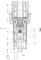
- Fig. 1 shows a longitudinal section of an agricultural sprayer valve unit 1, which can form an agricultural sprayer valve device 2 or can be part of it.
- the agricultural sprayer valve unit 1 has an input-side connection, not shown here, which opens into a primary line 3, and an output-side connection, not shown here, to which a secondary line 4 leads.
- the primary line 3 is connected to the secondary line 4 via an overflow valve 5 and an electronically controlled control valve 6.
- the primary line 3, the overflow valve 5, the control valve 6 and the secondary line 4 are arranged in this order in a fluidic series connection.
- An electronic actuation of the control valve 6 is possible via an electrical actuator 7, which has a holding magnet 8 for the exemplary embodiment shown.
- the holding magnet 8 acts on an armature 9, which carries a valve tappet 10.
- the holding magnet 8 is designed here as a pot magnet 11.
- the holding magnet 8 has an electromagnetically effective receiving body 12, which is designed in the manner of a horizontal U in the semi-longitudinal section.
- a coil 13 of the holding magnet 8 is embedded in the receiving body 12 between the two parallel legs of the lying U, the coil 12 being the in Fig. 1 horizontal actuation axis of the holding magnet 8 concentrically surrounds.
- the inner leg of the lying U in a semi-longitudinal section forms a solid core 14 arranged on the inside of the coil 13.
- the base leg of the lying U has a Passage 15, via which the coil 13 can be supplied with an external electrical input signal, for example via a cable or a plug 16.
- a spring acts between the holding magnet 8 and the armature 9, which is designed here as an opening spring 17 and acts on the armature 9 away from the holding magnet 8.
- the opening spring 17 is also pretensioned in the open position shown, so that the opening spring 17 rests with a spring base on the armature 9 and with the other spring base on the receiving body 12 with a preload force.
- the armature 9 In the de-energized state of the holding magnet 8, the armature 9 is in its open position due to the action of the opening spring 17.
- the control (which also includes regulation) of the electrical loading of the coil 14 of the holding magnet 8 takes place via a control unit 61.
- the agricultural sprayer valve unit 1 has a housing 18 which has housing parts 19, 20 which are connected to one another by means of a union nut 21.
- the housing delimits an interior 22, in which in particular the components of the overflow valve 5, the control valve 6 and the actuator 7 are arranged.
- the housing part 19 has a connection or passage 23 for the plug or cable 16. Furthermore, the housing 18 forms or carries the connections for the primary line 3 and the secondary line 4. The holding magnet 8 is attached to the housing 18 via a fastening screw 59.
- a housing insert 24 is arranged in the interior 22 of the housing 18.
- the housing insert 24 is designed in two parts with housing insert parts 25, 26.
- the housing insert 24 is held firmly in the housing 18 in the assembled state, which is ensured for the exemplary embodiment shown by the fact that a circumferential, radially outwardly oriented annular collar 27 over the union nut 21 is clamped between the end faces of the housing parts 19, 20.
- valve tappet 10 In the end region facing away from the armature 9 and protruding from the housing insert 24, the valve tappet 10 carries a control valve body 52, which forms an annular valve plate 53. In the contact area of the valve plate 53 with the control valve valve seat 45, the control valve valve body 52 has a sealing element 54, which is here at least partially embedded in an axial, circumferential groove of the valve plate 53.
- Fig. 6 shows an electrical application 62, here a current 63, with which the coil 13 of the holding magnet 8 is applied, during a period 64 of the pulse width modulation.
- the period 64 is divided into an ON phase 65, in which the control unit 61 carries out the required electrical loading 62 is applied to the coil 13, as well as an OFF phase 66, in which the electrical loading of the coil 13 is eliminated by the control unit 61.
- the ratio of the duration of the ON phase 65 to the period duration 64 which is between 0 and 1, is also referred to as the duty cycle.
- the duty cycle is approximately 0.45.
- the course 67 of the stream 63 is shown here.
- the course 67a characterizes the course of the stream 63 without any blockage when the fluid is being discharged
- the course 67b indicates the course of the stream 63 with less blockage when the fluid is being discharged
- the course 67c of the stream 63 the discharge of the fluid with a major or complete blockage.
- Fig. 6 It can be seen that the course during the OFF phase 66 changes significantly depending on the extent of the blockage.
- the courses 67a, 67b that are not completely blocked have a turning point, while the course 67c for complete blockage does not have a turning point.
- the course 67a has a more pronounced maximum 68a than the maximum 68b of the course 67b, while the course 67c does not have any maximum. From an evaluation of the curves 67 it can therefore be concluded whether there is a blockage or not. It is even possible to draw conclusions about the extent of the blockage (or a flow rate) (for example from evaluating the height of the maximum 68a, 68b) and to determine a relevant parameter.
- the opening pressure of the overflow valve 5 is preferably above 0.5 bar, 0.8 bar, 1.0 bar or 1.2 bar. It is possible, for example, that the opening pressure of the overflow valve 5 is in the range of 0.5 bar to 2.0 bar, 0.8 bar to 1.5 bar or 1.0 bar to 1.4 bar.
- the agricultural sprayer valve unit 1 is preferably operated in such a way that the control valve 6 is not opened more or less depending on the current supply. Rather, the actuator 7 is electrically acted upon in such a way that only a completely open position and a completely closed position are assumed (with the associated opening and closing movement between the open position and the closed position). It is possible for the open position and/or the closed position to be permanently controlled. However, it is also possible to use pulse width modulation with a resulting change between the open position and the closed position. In particular, pulse width modulation can take place with a frequency of 25 Hz.
- the control valve 6 is preferably opened with pressure support from the fluid, which means that a rapid opening movement can take place.
- This takes advantage of the fact that in the closed position of the control valve 6, a dynamic pressure builds up on the input side of the control valve 6, which is higher than the pressure on the output side, which results in a force acting in the opening direction.
- the closing movement basically takes place against the pressure of the fluid.
- the pressure difference between the input side and the output side is at least reduced in the open position as a result of the pressure equalization made possible in the open position, so that a force generated by the pressure of the fluid, which is opposite to the closing movement, is at least reduced.
- a special test operation of the actuator 7 takes place to detect whether the agricultural sprayer valve unit 1 is working properly and in particular whether it is not blocked.
- an opening of the agricultural sprayer valve unit 1 and a subsequent closure of the agricultural sprayer valve unit 1 can be specifically controlled, in which case the currents or voltages are then used for evaluation, in particular for detecting a possible blockage.
- the curves 67, 71 shown between times t1 and t6 relate to the generation of a holding voltage 72 for closing the holding magnet 8 at a time t1 from an open position of the holding magnet 8, the reduction of the air gap of the holding magnet 8 from a time t2, reaching the closed position at a time t3, detecting that the closed position has been reached at a time t4, reducing the voltage 70 to 0 at a time t5 to reopen the holding magnet 8 and reaching the open position and possibly also maintaining it up to a time t6.
- the curves shown between the times t1 and t6 apply, for example, during pulse width modulation, so that the time t6 is immediately followed by another section corresponding to the curve shown between the times t1 and t6 and the duty cycle is specified by the choice of time t5.
- the holding magnet 8 and the control valve 6 it is also possible for the holding magnet 8 and the control valve 6 to remain in the open position before time t1 and/or after time t6, so that individual control to bring about the closed position and also measurement of the period of time for maintaining the closed position can take place.
- a temporary closure of the holding magnet 8 and the control valve 6 also takes place for test purposes, which can be brought about once or repeatedly or on a regular basis, for example in order to detect a blockage of the control valve 6 (and/or the flow cross sections arranged upstream and/or downstream).
- Fig. 7 the increase in current 63 from 0 can be seen from time t1. While initially the current 63 increases linearly, reducing the gap results in a reduction in the slope of the current increase until a maximum is reached. The current 63 then drops as it approaches the closed position until a threshold value 73 of the current 63 is reached at time t3. Since the gap of the holding magnet 8 is closed from time t3, the course 67d of the current 63 then increases linearly again until it approaches an asymptotic saturation value. If the voltage 70 is reduced again to 0 at time t5 to bring about the open position of the control valve 6, the course 67d of the current 63 initially drops linearly. When the movement of the holding magnet 8 is triggered, the slope of the drop in the current 63 changes slightly and then asymptotically approaches zero current.
- Fig. 8 shows that in the period between t3 and t5, the closed position of the holding magnet 8 and thus of the control valve 6 can be maintained even if different Fig. 7 During this period, the voltage 70 is not held at the holding voltage 72, but the voltage 70 is switched back and forth between the holding voltage 72, which forms a maximum, and a voltage of zero, which thus forms a minimum, oscillating at a constant frequency, from which this in Fig. 8b
- the square wave signal shown results in the period between t4 and t5.
- a control logic of a control unit determines at a time t4 that the holding magnet 8 and the control valve 6 have reached the closed position.
- t4 is identical to t3, although a small period of time between t3 and t4 may be required for the evaluation and signal processing by the control unit.
- the control logic of the control unit triggers the oscillating switching back and forth of the voltage 70. Reducing the voltage 70 to zero does not directly lead to a reduction in the current 63 according to the curve 67e. Rather, the current 63 reduces with a relatively small gradient, for which the cause may be the opposing field indicated in the coil 13 with the core 14 of the holding magnet 8.
- the frequency of the oscillating switching back and forth of the voltage 70 is dimensioned such that the increase in the current 63 resulting from the electromagnetic variables of the holding magnet 8 within the switch-off period of the voltage results in the current 63 only reaching a minimum current 74 and does not fall below.
- This minimum current 74 is (just) enough to keep the holding magnet 8 and the control valve 6 in the closed position.
- the timely generation of the holding voltage 72 when the minimum current 74 is reached then causes the current 63 to increase again in accordance with the curve 67e. This increase then takes place up to a maximum current 75.
- the voltage 70 drops back to zero according to the curve 71e and the process can then be repeated several times. That according to Fig. 8
- the method used for oscillating reduction of the voltage 70 leads to a reduction in the electrical power consumption of the control valve 6 in the closed position of the same.
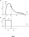
- Fig. 9 shows the generation of a test signal in order to be able to determine whether the control valve 6 (and/or an application nozzle or a secondary line) is clogged.
- the voltage 70 is increased to the holding voltage 72 at time t1.
- the course 67f of the current 63 corresponds to the course 67e of the current 63 Fig. 8 and the course 71f of the voltage 70 corresponds to the course 71e of the voltage 70 Fig. 8 .
- the voltage 70 is immediately reduced to zero again according to the course 71f, so that the Opening position is brought about and thus the closed position of the control valve 6 is kept as short as possible.
- the gap of the holding magnet 8 is closed for a period of time that approaches zero, so that fluid can be discharged from the control valve 6 almost continuously.
- the aim of the test signal generated in this way is then to evaluate the course 67f of the current 63 after time t4.
- a turning point of the course 67f and/or a maximum is formed for the course 67f shown with a solid line with the control valve 6 not or only slightly clogged, while for the dashed line shown course 67f this turning point or the maximum are no longer present.
- the amount of the maximum and/or the extent of a turning point can thus be evaluated to determine whether there is a blockage.
- a test signal according to Fig. 9 can be generated regularly or only temporarily exclusively for these test purposes. But it is also possible that the in Fig. 9
- the curves 67f, 71f shown between the times t1 and t6 are part of a pulse width modulated signal, so that a signal can be used for the evaluation, which is already available as a result of the pulse width modulation and not an additional closure of the control valve 6, which is not necessary in itself monitoring of constipation is required.
- the time period of closure t1 to t3 or t1 to t4 is preferably chosen to be as short as possible, which is preferably less than 100 msec, less than 50 msec or even less than 45 msec.
Landscapes
- Engineering & Computer Science (AREA)
- General Engineering & Computer Science (AREA)
- Mechanical Engineering (AREA)
- Chemical & Material Sciences (AREA)
- Analytical Chemistry (AREA)
- Power Engineering (AREA)
- Physics & Mathematics (AREA)
- General Physics & Mathematics (AREA)
- Automation & Control Theory (AREA)
- Life Sciences & Earth Sciences (AREA)
- Insects & Arthropods (AREA)
- Pest Control & Pesticides (AREA)
- Wood Science & Technology (AREA)
- Zoology (AREA)
- Environmental Sciences (AREA)
- Catching Or Destruction (AREA)
Claims (16)
- Unité de soupape de pulvérisation agricole (1) avec une conduite primaire (3) et une conduite secondaire (4) et une soupape de commande contrôlée électroniquement (6), disposée entre la conduite primaire (3) et la conduite secondaire (4), dans laquellea) une position de soupape de la soupape de commande (6) peut être maintenue et/ou modifiée par l'intermédiaire d'un aimant de fixation (8),
caractérisée en ce queb) une soupape de décharge passive (5) est branchée en série à la soupape de commande contrôlée électroniquement (6), entre la conduite primaire (3) et la conduite secondaire (4) etc) la pression dans la conduite primaire (3) agit, dans une position de fermeture de la soupape de décharge (5), sur une surface de soupape de la soupape de décharge (5) plus petite que dans une position d'ouverture de la soupape de décharge (5). - Unité de soupape de pulvérisation agricole (1) selon la revendication 1, caractérisée en ce que la soupape de commande contrôlée électroniquement (6) prend sa position d'ouverture lorsque l'aimant de fixation (8) n'est pas alimenté en courant.
- Unité de soupape de pulvérisation agricole (1) selon l'une des revendications précédentes, caractérisée en ce quea) la soupape de commande contrôlée électroniquement (6) comprend un corps de soupape de commande (52),b) la soupape de décharge (5) comprend un corps de soupape de décharge (40) etc) un corps de siège de soupape commun (43) constitue aussi bien le siège de soupape de commande (45) de la soupape de commande contrôlée électroniquement (6), contre lequel le corps de soupape de commande (52) s'appuie dans la position de fermeture de la soupape de commande contrôlée électroniquement (6), que le siège de soupape de décharge (44) de la soupape de décharge (5), contre lequel le corps de soupape de décharge (40) s'appuie dans la position de fermeture de la soupape de décharge (5).
- Unité de soupape de pulvérisation agricole (1) selon l'une des revendications précédentes, caractérisée en ce que la soupape de décharge (5) et la soupape de commande contrôlée électroniquement (6) sont imbriquées radialement l'une dans l'autre.
- Unité de soupape de pulvérisation agricole (1) selon l'une des revendications précédentes, caractérisée en ce quea) si la revendication se réfère à la revendication 1, 2 ou 4, sans se référer à la revendication 3, la soupape de décharge (5) comprend un corps de soupape de décharge (40) qui présente un évidement de passage (60), dans lequel un canal (35) entre la soupape de décharge (5) et la soupape de commande contrôlée électroniquement (6) et/ou un composant de la soupape de commande contrôlée électroniquement (6) s'étend(ent) au moins partiellement à travers l'évidement de passage (60) oub) si la revendication se réfère à la revendication 3 ou 4, en se référant à la revendication 3, le corps de soupape de décharge (40) présente un évidement de passage (60), dans lequel un canal (35) entre la soupape de décharge (5) et la soupape de commande contrôlée électroniquement (6) et/ou un composant de la soupape de commande contrôlée électroniquement (6) s'étend(ent) au moins partiellement à travers l'évidement de passage (60).
- Unité de soupape de pulvérisation agricole (1) selon l'une des revendications précédentes, caractérisée en ce qu'un boîtier (18) avec un espace interne (22) est prévu, dans laquellea) le ou un corps de soupape de décharge (40),b) le ou un corps de soupape de commande (52) etc) le ou au moins un corps de siège de soupape (43), qui constitue le siège de soupape de décharge et/ou le siège de soupape de commande,sont réalisés séparément du boîtier (18) et sont disposés dans l'espace interne (22) du boîtier (18).
- Dispositif à soupape de pulvérisation agricole (2) avec une unité de soupape de pulvérisation agricole (1) selon l'une des revendications précédentes, caractérisé en ce qu'une unité de commande (61) avec une logique de commande est prévue, qui détermine, à partir de l'alimentation électrique de l'aimant de fixation (8), au moins une grandeur caractéristique qui est corrélée au moins avec un débit et/ou une étendue d'un colmatagea) de l'unité de soupape de pulvérisation agricole (1),b) de la conduite secondaire (4) et/ouc) d'une buse de sortie.
- Dispositif à soupape de pulvérisation agricole (2) selon la revendication 7, caractérisé en ce que la logique de commande est conçue de sorte que l'aimant de fixation (8) est alimenté électriquement au moyen d'une modulation de largeur d'impulsion et la grandeur caractéristique est déterminée sur la base de l'alimentation électrique,
dans lequel la logique de commande est plus particulièrement conçue de sorte que la grandeur caractéristique est déterminée sur la base de l'alimentation électriquea) pendant la phase OFF (66) de la modulation de largeur d'impulsion ou le mouvement de fermeture de la soupape de commande contrôlée électroniquement (6) oub) pendant la phase ON (66) de la modulation de largeur d'impulsion ou le mouvement d'ouverture de la soupape de commande contrôlée électroniquement (6). - Dispositif à soupape de pulvérisation agricole (2) selon la revendication 8, caractérisé en ce que la logique de commande est conçue de sorte que la grandeur caractéristique est déterminée à partir d'un maximum local (68) de l'alimentation électriquea) pendant la phase OFF (66) de la modulation de largeur d'impulsion ou le mouvement de fermeture de la soupape de commande contrôlée électroniquement (6) oub) pendant la phase ON (66) de la modulation de largeur d'impulsion ou le mouvement d'ouverture de la soupape de commande contrôlée électroniquement (6).
- Dispositif à soupape de pulvérisation agricole (2) selon l'une des revendications 7 à 9, caractérisé en ce que la logique de commande est conçue de sorte que la grandeur caractéristique est déterminée pour plusieurs cycles de la modulation de largeur d'impulsion et une variation de la grandeur caractéristique permet de déduire une variation du débit et/ou d'une étendue d'un colmatage.
- Dispositif à soupape de pulvérisation agricole (2) selon l'une des revendications 7 à 10, caractérisé en ce que plusieurs unités de soupapes de pulvérisation agricole (1) sont prévues, qui correspondent chacune à une buse de sortie, dans lequel les unités de soupapes de pulvérisation agricole (1) avec les buses de sortie correspondantes sont maintenues sur une barre de pulvérisation et sont alimentées par l'intermédiaire d'une pompe avec un fluide à pulvériser, et au moins une unité de commande électronique (61) est prévue, qui contrôle au moins une unité de soupape de pulvérisation agricole (1) correspondante.
- Dispositif à soupape de pulvérisation agricole (2) selon l'une des revendications 7 à 11, caractérisé en ce que la logique de commandea) contrôle, pendant un fonctionnement en continu de l'unité de soupape de pulvérisation agricole (1) ou pour un fonctionnement de test ou de référence, dans une position d'ouverture, aussi bien de la soupape de commande (6) que de la soupape de décharge passive (5), la soupape de commande (6), de manière temporaire ou répétée afin de la mettre dans une position de fermeture etb) une alimentation électrique (62) de l'aimant de fixation (8) est déterminée, qui est ensuite prise en compte pour la détermination d'un débit et/ou d'une étendue d'un colmatage de l'unité de soupape de pulvérisation agricole (1), de la conduite secondaire (4) ou d'une buse de sortie,dans lequel l'unité de commande contrôle plus particulièrement plusieurs unités de soupapes de pulvérisation agricole (1) et la logique de commande contrôle les soupapes de commande (6) des unités de soupapes de pulvérisation agricole (1) de manière décalée dans le temps à des fins de test ou de référence, afin de la mettre dans une position de fermeture.
- Dispositif à soupape de pulvérisation agricole (2) selon l'une des revendications 7 à 12, caractérisé en ce que la logique de commandea) contrôle, dans un fonctionnement de référence, la soupape de commande (6) afin de la mettre dans une position de fermeture,b) enregistre l'alimentation électrique (62) de l'aimant de fixation (8), mesurée pendant le fonctionnement de référence, en tant qu'alimentation de référence,c) contrôle, dans un fonctionnement de test, la soupape de commande (6) afin de mettre dans une position de fermeture etd) une étendue d'un colmatage de l'unité de soupape de pulvérisation agricole (1), de la conduite secondaire (4) et/ou d'une buse de sortie est déterminée grâce à une comparaison de l'alimentation de référence avec l'alimentation électrique mesurée pendant le fonctionnement de test.
- Dispositif à soupape de pulvérisation agricole (2) selon la revendication 13, caractérisé en ce qu'un fonctionnement de référence est exécuté pour différentes pressions dans la conduite primaire et plusieurs alimentations de référence sont enregistrées en fonction de la pression et une étendue d'un colmatage de l'unité de soupape de pulvérisation agricole (1), de la conduite secondaire (4) et/ou d'une buse de sortie est déterminée grâce à une comparaison de l'alimentation de référence pour la pression qui a été appliquée pendant le fonctionnement de test dans la conduite primaire avec l'alimentation électrique mesurée pendant le fonctionnement de test.
- Dispositif à soupape de pulvérisation agricole (2) selon l'une des revendications 7 à 14, caractérisé en ce que la logique de commande fait varier, dans une position de fermeture de la soupape de commande (6), l'alimentation électrique, plus particulièrement de manière oscillante entre un maximum et un minimum.
- Dispositif à soupape de pulvérisation agricole (2) selon l'une des revendications 7 à 15, caractérisé en ce que la logique de commandea) surveille, lors d'un passage de la soupape de commande (6) d'une position d'ouverture vers une position de fermeture, l'évolution du courant (63) avec lequel l'aimant de fixation (8) est alimenté etb) le moment où la position de fermeture de la soupape de commande (6) est atteinte est déterminé à partir de l'évolution du courant (63) avec lequel l'aimant de fixation (8) est alimenté, de la manière suivante :- une diminution du courant (63) à ou en dessous d'une valeur seuil (73) est détectée et/ou une augmentation suivante du courant (63) est détectée et/ou- un point d'inflexion du courant (63) en diminution est détecté et/ou- une instabilité du courant (63) en diminution est détectée.
Applications Claiming Priority (2)
| Application Number | Priority Date | Filing Date | Title |
|---|---|---|---|
| EP18189451.0A EP3610954A1 (fr) | 2018-08-17 | 2018-08-17 | Unité de soupape de pulvérisation agricole et dispositif de soupape de pulvérisation agricole |
| PCT/EP2019/071573 WO2020035443A1 (fr) | 2018-08-17 | 2019-08-12 | Unité de soupape pour pulvérisateur agricole et dispositif de soupape pour pulvérisateur agricole |
Publications (3)
| Publication Number | Publication Date |
|---|---|
| EP3837060A1 EP3837060A1 (fr) | 2021-06-23 |
| EP3837060B1 true EP3837060B1 (fr) | 2024-02-14 |
| EP3837060C0 EP3837060C0 (fr) | 2024-02-14 |
Family
ID=63294132
Family Applications (2)
| Application Number | Title | Priority Date | Filing Date |
|---|---|---|---|
| EP18189451.0A Withdrawn EP3610954A1 (fr) | 2018-08-17 | 2018-08-17 | Unité de soupape de pulvérisation agricole et dispositif de soupape de pulvérisation agricole |
| EP19752703.9A Active EP3837060B1 (fr) | 2018-08-17 | 2019-08-12 | Unité de soupape de pulvérisation agricole et dispositif de soupape de pulvérisation agricole |
Family Applications Before (1)
| Application Number | Title | Priority Date | Filing Date |
|---|---|---|---|
| EP18189451.0A Withdrawn EP3610954A1 (fr) | 2018-08-17 | 2018-08-17 | Unité de soupape de pulvérisation agricole et dispositif de soupape de pulvérisation agricole |
Country Status (5)
| Country | Link |
|---|---|
| US (1) | US11890629B2 (fr) |
| EP (2) | EP3610954A1 (fr) |
| CN (1) | CN112601614B (fr) |
| RU (1) | RU2764551C1 (fr) |
| WO (1) | WO2020035443A1 (fr) |
Families Citing this family (5)
| Publication number | Priority date | Publication date | Assignee | Title |
|---|---|---|---|---|
| EP4080315B1 (fr) | 2021-04-23 | 2023-12-06 | IWN GmbH & Co. KG | Procédé de fonctionnement d'un dispositif de pulvérisation agricole et dispositif de pulvérisation agricole |
| US11980113B2 (en) | 2021-05-17 | 2024-05-14 | Cnh Industrial America Llc | System and method for adjusting actuator pressure on an agricultural implement using a valve |
| EP4147786B1 (fr) | 2021-09-08 | 2024-05-15 | Reinhold Schulte | Unité de soupape de pulvérisation agricole et dispositif de pulvérisation agricole |
| EP4397182B1 (fr) | 2023-01-06 | 2025-09-24 | Reinhold Schulte | Système d'épandage de fluide agricole |
| CN119712766A (zh) * | 2024-12-13 | 2025-03-28 | 杰锋汽车动力系统股份有限公司 | 一种膜片式空气弹簧刚度阀 |
Citations (1)
| Publication number | Priority date | Publication date | Assignee | Title |
|---|---|---|---|---|
| GB2337984A (en) * | 1998-05-27 | 1999-12-08 | Matthew James Harold Rawlings | Liquid spraying apparatus |
Family Cites Families (21)
| Publication number | Priority date | Publication date | Assignee | Title |
|---|---|---|---|---|
| JPH0692743B2 (ja) * | 1985-04-01 | 1994-11-16 | 日本電装株式会社 | 流体制御用電磁弁 |
| HU198116B (en) * | 1986-11-06 | 1989-08-28 | Debreceni Mezoegazdasagi | Spraying machine particularly for area-proportional spreading spray liquor |
| CN2042140U (zh) * | 1988-03-31 | 1989-08-02 | 邢学恩 | 防止流体滴(溢)漏的控制阀 |
| SE500519C2 (sv) * | 1992-02-11 | 1994-07-11 | Sven Linderoth | Tryckreglerare för reglering av spruttrycket till ett flertal munstycken i förhållande till pumpkapaciteten |
| US5450881A (en) * | 1993-12-03 | 1995-09-19 | Murray Equipment, Inc. | Liquid chemical measuring and distribution system |
| US5653389A (en) | 1995-09-15 | 1997-08-05 | Henderson; Graeme W. | Independent flow rate and droplet size control system and method for sprayer |
| JPH1182220A (ja) * | 1997-09-12 | 1999-03-26 | Nissan Motor Co Ltd | ディーゼルエンジンの燃料噴射制御装置 |
| JP3065601B1 (ja) * | 1999-02-26 | 2000-07-17 | 古河機械金属株式会社 | 圧力制御弁 |
| US7306167B2 (en) * | 2004-10-21 | 2007-12-11 | Nch Corporation | Light-activated mist sprayer system |
| US20060273189A1 (en) * | 2005-06-07 | 2006-12-07 | Capstan Ag Systems, Inc. | Electrically actuated variable pressure control system |
| US20100072301A1 (en) | 2008-09-19 | 2010-03-25 | Miro Cater | Discharge device |
| DE102009001532A1 (de) | 2009-03-13 | 2011-08-04 | Schulte, Reinhold, 33106 | Agrare Ausbringeinrichtung für das Ausbringen von Fluiden |
| US8864053B2 (en) * | 2009-05-11 | 2014-10-21 | Caterpillar Inc. | Spray head for a mobile fluid distribution system |
| DE102010001881B4 (de) * | 2010-02-12 | 2012-08-30 | Reinhold Schulte | Agrarspritzen-Ventileinheit |
| DE102011000921B3 (de) | 2011-02-24 | 2012-07-05 | Reinhold Schulte | Agrarspritzen-Überströmventil |
| CN202834247U (zh) * | 2012-09-05 | 2013-03-27 | 北京工业大学 | 一种纯水液压电磁卸荷溢流阀 |
| DE102013101460B3 (de) | 2013-02-14 | 2014-02-13 | Reinhold Schulte | Agrarspritzen-Ventileinheit |
| EP2979765B1 (fr) | 2014-07-28 | 2017-01-11 | Reinhold Schulte | Unité de soupape à pulvérisation agricole |
| US10444048B2 (en) * | 2014-12-19 | 2019-10-15 | Deere & Company | Fluid flow monitoring system |
| KR101778076B1 (ko) * | 2016-03-31 | 2017-09-13 | (주) 현대 테크 | 농약 살포장치 |
| DE112017003084B4 (de) * | 2016-06-21 | 2025-08-07 | Raven Industries, Inc. | Düsensteuersystem und -verfahren |
-
2018
- 2018-08-17 EP EP18189451.0A patent/EP3610954A1/fr not_active Withdrawn
-
2019
- 2019-08-12 CN CN201980054478.3A patent/CN112601614B/zh active Active
- 2019-08-12 RU RU2021106700A patent/RU2764551C1/ru active
- 2019-08-12 EP EP19752703.9A patent/EP3837060B1/fr active Active
- 2019-08-12 WO PCT/EP2019/071573 patent/WO2020035443A1/fr not_active Ceased
-
2021
- 2021-02-16 US US17/176,974 patent/US11890629B2/en active Active
Patent Citations (1)
| Publication number | Priority date | Publication date | Assignee | Title |
|---|---|---|---|---|
| GB2337984A (en) * | 1998-05-27 | 1999-12-08 | Matthew James Harold Rawlings | Liquid spraying apparatus |
Also Published As
| Publication number | Publication date |
|---|---|
| RU2764551C1 (ru) | 2022-01-18 |
| US20210162443A1 (en) | 2021-06-03 |
| CN112601614B (zh) | 2024-03-19 |
| BR112021002746A2 (pt) | 2021-05-11 |
| WO2020035443A1 (fr) | 2020-02-20 |
| CN112601614A (zh) | 2021-04-02 |
| US11890629B2 (en) | 2024-02-06 |
| EP3610954A1 (fr) | 2020-02-19 |
| EP3837060C0 (fr) | 2024-02-14 |
| EP3837060A1 (fr) | 2021-06-23 |
Similar Documents
| Publication | Publication Date | Title |
|---|---|---|
| EP3837060B1 (fr) | Unité de soupape de pulvérisation agricole et dispositif de soupape de pulvérisation agricole | |
| DE3855969T2 (de) | Elektromagnetisch betätigbare Vorrichtung zum schnellen Umschalten eines elektro-hydraulisch betätigten Kraftstoffeinspritzventils | |
| DE102009001532A1 (de) | Agrare Ausbringeinrichtung für das Ausbringen von Fluiden | |
| WO2010085991A2 (fr) | Soupape de régulation de pression proportionnelle | |
| EP2979765B1 (fr) | Unité de soupape à pulvérisation agricole | |
| EP0837275B1 (fr) | Electrovanne d'évacuation de levage électrohydraulique | |
| WO2016134909A1 (fr) | Soupape servant à commuter des fluides, installation d'extinction d'incendie et procédé | |
| EP3001080A1 (fr) | Soupape de reduction de pression dotee d'alesages radiaux superposes pour differents chemins d'ecoulement de fluide | |
| EP3039501B1 (fr) | Dispositif de soupape | |
| EP0777597A1 (fr) | Procede et dispositif d'excitation d'une electrovanne | |
| EP2558758B1 (fr) | Régulateur de débit | |
| DE102011116393B3 (de) | Vorsteuerstufe eines proportional gesteuerten Hydraulikventils | |
| DE102010001881B4 (de) | Agrarspritzen-Ventileinheit | |
| EP1630425A2 (fr) | Circuit de sécurité pour un utilisateur à actionnement par fluide et méthode pour son utilisation | |
| CH658304A5 (de) | Den durchfluss eines druckmediums steuerndes umschaltventil. | |
| EP4080315B1 (fr) | Procédé de fonctionnement d'un dispositif de pulvérisation agricole et dispositif de pulvérisation agricole | |
| DE102013101460B3 (de) | Agrarspritzen-Ventileinheit | |
| DE60108898T2 (de) | Elektromagnetisches zweiwegeventil | |
| EP3308236B1 (fr) | Dispositif de régulation de pression | |
| EP1151363B2 (fr) | Soupape proportionnelle de regulation de la pression | |
| WO2000018382A2 (fr) | Distributeur hydraulique | |
| DE102015111222A1 (de) | Lastkompensiertes Proportional-Drosselventil | |
| EP3821985B1 (fr) | Unité de soupape de pulvérisation agricole, dispositif de pulvérisation agricole, dispositif d'épandage agricole et procédé de fonctionnement d'une unité de soupape de pulvérisation agricole | |
| DE2712491C2 (de) | Elektromagnetisch betätigtes, druckgesteuertes Ventil | |
| DE19908899B4 (de) | Elektromagnetventil |
Legal Events
| Date | Code | Title | Description |
|---|---|---|---|
| STAA | Information on the status of an ep patent application or granted ep patent |
Free format text: STATUS: UNKNOWN |
|
| STAA | Information on the status of an ep patent application or granted ep patent |
Free format text: STATUS: THE INTERNATIONAL PUBLICATION HAS BEEN MADE |
|
| PUAI | Public reference made under article 153(3) epc to a published international application that has entered the european phase |
Free format text: ORIGINAL CODE: 0009012 |
|
| STAA | Information on the status of an ep patent application or granted ep patent |
Free format text: STATUS: REQUEST FOR EXAMINATION WAS MADE |
|
| 17P | Request for examination filed |
Effective date: 20210216 |
|
| AK | Designated contracting states |
Kind code of ref document: A1 Designated state(s): AL AT BE BG CH CY CZ DE DK EE ES FI FR GB GR HR HU IE IS IT LI LT LU LV MC MK MT NL NO PL PT RO RS SE SI SK SM TR |
|
| DAV | Request for validation of the european patent (deleted) | ||
| DAX | Request for extension of the european patent (deleted) | ||
| STAA | Information on the status of an ep patent application or granted ep patent |
Free format text: STATUS: EXAMINATION IS IN PROGRESS |
|
| 17Q | First examination report despatched |
Effective date: 20220923 |
|
| GRAP | Despatch of communication of intention to grant a patent |
Free format text: ORIGINAL CODE: EPIDOSNIGR1 |
|
| STAA | Information on the status of an ep patent application or granted ep patent |
Free format text: STATUS: GRANT OF PATENT IS INTENDED |
|
| GRAJ | Information related to disapproval of communication of intention to grant by the applicant or resumption of examination proceedings by the epo deleted |
Free format text: ORIGINAL CODE: EPIDOSDIGR1 |
|
| STAA | Information on the status of an ep patent application or granted ep patent |
Free format text: STATUS: EXAMINATION IS IN PROGRESS |
|
| INTG | Intention to grant announced |
Effective date: 20230928 |
|
| GRAP | Despatch of communication of intention to grant a patent |
Free format text: ORIGINAL CODE: EPIDOSNIGR1 |
|
| STAA | Information on the status of an ep patent application or granted ep patent |
Free format text: STATUS: GRANT OF PATENT IS INTENDED |
|
| INTC | Intention to grant announced (deleted) | ||
| INTG | Intention to grant announced |
Effective date: 20231031 |
|
| GRAS | Grant fee paid |
Free format text: ORIGINAL CODE: EPIDOSNIGR3 |
|
| GRAA | (expected) grant |
Free format text: ORIGINAL CODE: 0009210 |
|
| STAA | Information on the status of an ep patent application or granted ep patent |
Free format text: STATUS: THE PATENT HAS BEEN GRANTED |
|
| AK | Designated contracting states |
Kind code of ref document: B1 Designated state(s): AL AT BE BG CH CY CZ DE DK EE ES FI FR GB GR HR HU IE IS IT LI LT LU LV MC MK MT NL NO PL PT RO RS SE SI SK SM TR |
|
| REG | Reference to a national code |
Ref country code: GB Ref legal event code: FG4D Free format text: NOT ENGLISH |
|
| REG | Reference to a national code |
Ref country code: CH Ref legal event code: EP |
|
| REG | Reference to a national code |
Ref country code: DE Ref legal event code: R096 Ref document number: 502019010595 Country of ref document: DE |
|
| REG | Reference to a national code |
Ref country code: IE Ref legal event code: FG4D Free format text: LANGUAGE OF EP DOCUMENT: GERMAN |
|
| U01 | Request for unitary effect filed |
Effective date: 20240215 |
|
| U07 | Unitary effect registered |
Designated state(s): AT BE BG DE DK EE FI FR IT LT LU LV MT NL PT SE SI Effective date: 20240226 |
|
| PG25 | Lapsed in a contracting state [announced via postgrant information from national office to epo] |
Ref country code: IS Free format text: LAPSE BECAUSE OF FAILURE TO SUBMIT A TRANSLATION OF THE DESCRIPTION OR TO PAY THE FEE WITHIN THE PRESCRIBED TIME-LIMIT Effective date: 20240614 |
|
| U20 | Renewal fee for the european patent with unitary effect paid |
Year of fee payment: 6 Effective date: 20240603 |
|
| PG25 | Lapsed in a contracting state [announced via postgrant information from national office to epo] |
Ref country code: GR Free format text: LAPSE BECAUSE OF FAILURE TO SUBMIT A TRANSLATION OF THE DESCRIPTION OR TO PAY THE FEE WITHIN THE PRESCRIBED TIME-LIMIT Effective date: 20240515 |
|
| PG25 | Lapsed in a contracting state [announced via postgrant information from national office to epo] |
Ref country code: RS Free format text: LAPSE BECAUSE OF FAILURE TO SUBMIT A TRANSLATION OF THE DESCRIPTION OR TO PAY THE FEE WITHIN THE PRESCRIBED TIME-LIMIT Effective date: 20240514 Ref country code: HR Free format text: LAPSE BECAUSE OF FAILURE TO SUBMIT A TRANSLATION OF THE DESCRIPTION OR TO PAY THE FEE WITHIN THE PRESCRIBED TIME-LIMIT Effective date: 20240214 |
|
| PG25 | Lapsed in a contracting state [announced via postgrant information from national office to epo] |
Ref country code: ES Free format text: LAPSE BECAUSE OF FAILURE TO SUBMIT A TRANSLATION OF THE DESCRIPTION OR TO PAY THE FEE WITHIN THE PRESCRIBED TIME-LIMIT Effective date: 20240214 |
|
| PG25 | Lapsed in a contracting state [announced via postgrant information from national office to epo] |
Ref country code: RS Free format text: LAPSE BECAUSE OF FAILURE TO SUBMIT A TRANSLATION OF THE DESCRIPTION OR TO PAY THE FEE WITHIN THE PRESCRIBED TIME-LIMIT Effective date: 20240514 Ref country code: NO Free format text: LAPSE BECAUSE OF FAILURE TO SUBMIT A TRANSLATION OF THE DESCRIPTION OR TO PAY THE FEE WITHIN THE PRESCRIBED TIME-LIMIT Effective date: 20240514 Ref country code: IS Free format text: LAPSE BECAUSE OF FAILURE TO SUBMIT A TRANSLATION OF THE DESCRIPTION OR TO PAY THE FEE WITHIN THE PRESCRIBED TIME-LIMIT Effective date: 20240614 Ref country code: HR Free format text: LAPSE BECAUSE OF FAILURE TO SUBMIT A TRANSLATION OF THE DESCRIPTION OR TO PAY THE FEE WITHIN THE PRESCRIBED TIME-LIMIT Effective date: 20240214 Ref country code: GR Free format text: LAPSE BECAUSE OF FAILURE TO SUBMIT A TRANSLATION OF THE DESCRIPTION OR TO PAY THE FEE WITHIN THE PRESCRIBED TIME-LIMIT Effective date: 20240515 Ref country code: ES Free format text: LAPSE BECAUSE OF FAILURE TO SUBMIT A TRANSLATION OF THE DESCRIPTION OR TO PAY THE FEE WITHIN THE PRESCRIBED TIME-LIMIT Effective date: 20240214 |
|
| PG25 | Lapsed in a contracting state [announced via postgrant information from national office to epo] |
Ref country code: PL Free format text: LAPSE BECAUSE OF FAILURE TO SUBMIT A TRANSLATION OF THE DESCRIPTION OR TO PAY THE FEE WITHIN THE PRESCRIBED TIME-LIMIT Effective date: 20240214 |
|
| PG25 | Lapsed in a contracting state [announced via postgrant information from national office to epo] |
Ref country code: PL Free format text: LAPSE BECAUSE OF FAILURE TO SUBMIT A TRANSLATION OF THE DESCRIPTION OR TO PAY THE FEE WITHIN THE PRESCRIBED TIME-LIMIT Effective date: 20240214 |
|
| PG25 | Lapsed in a contracting state [announced via postgrant information from national office to epo] |
Ref country code: SM Free format text: LAPSE BECAUSE OF FAILURE TO SUBMIT A TRANSLATION OF THE DESCRIPTION OR TO PAY THE FEE WITHIN THE PRESCRIBED TIME-LIMIT Effective date: 20240214 |
|
| PG25 | Lapsed in a contracting state [announced via postgrant information from national office to epo] |
Ref country code: CZ Free format text: LAPSE BECAUSE OF FAILURE TO SUBMIT A TRANSLATION OF THE DESCRIPTION OR TO PAY THE FEE WITHIN THE PRESCRIBED TIME-LIMIT Effective date: 20240214 |
|
| PG25 | Lapsed in a contracting state [announced via postgrant information from national office to epo] |
Ref country code: SK Free format text: LAPSE BECAUSE OF FAILURE TO SUBMIT A TRANSLATION OF THE DESCRIPTION OR TO PAY THE FEE WITHIN THE PRESCRIBED TIME-LIMIT Effective date: 20240214 |
|
| PG25 | Lapsed in a contracting state [announced via postgrant information from national office to epo] |
Ref country code: SM Free format text: LAPSE BECAUSE OF FAILURE TO SUBMIT A TRANSLATION OF THE DESCRIPTION OR TO PAY THE FEE WITHIN THE PRESCRIBED TIME-LIMIT Effective date: 20240214 Ref country code: SK Free format text: LAPSE BECAUSE OF FAILURE TO SUBMIT A TRANSLATION OF THE DESCRIPTION OR TO PAY THE FEE WITHIN THE PRESCRIBED TIME-LIMIT Effective date: 20240214 Ref country code: RO Free format text: LAPSE BECAUSE OF FAILURE TO SUBMIT A TRANSLATION OF THE DESCRIPTION OR TO PAY THE FEE WITHIN THE PRESCRIBED TIME-LIMIT Effective date: 20240214 Ref country code: CZ Free format text: LAPSE BECAUSE OF FAILURE TO SUBMIT A TRANSLATION OF THE DESCRIPTION OR TO PAY THE FEE WITHIN THE PRESCRIBED TIME-LIMIT Effective date: 20240214 |
|
| REG | Reference to a national code |
Ref country code: DE Ref legal event code: R097 Ref document number: 502019010595 Country of ref document: DE |
|
| PLBE | No opposition filed within time limit |
Free format text: ORIGINAL CODE: 0009261 |
|
| STAA | Information on the status of an ep patent application or granted ep patent |
Free format text: STATUS: NO OPPOSITION FILED WITHIN TIME LIMIT |
|
| 26N | No opposition filed |
Effective date: 20241115 |
|
| REG | Reference to a national code |
Ref country code: CH Ref legal event code: PL |
|
| GBPC | Gb: european patent ceased through non-payment of renewal fee |
Effective date: 20240812 |
|
| PG25 | Lapsed in a contracting state [announced via postgrant information from national office to epo] |
Ref country code: MC Free format text: LAPSE BECAUSE OF FAILURE TO SUBMIT A TRANSLATION OF THE DESCRIPTION OR TO PAY THE FEE WITHIN THE PRESCRIBED TIME-LIMIT Effective date: 20240214 Ref country code: CH Free format text: LAPSE BECAUSE OF NON-PAYMENT OF DUE FEES Effective date: 20240831 |
|
| U20 | Renewal fee for the european patent with unitary effect paid |
Year of fee payment: 7 Effective date: 20250605 |
|
| PG25 | Lapsed in a contracting state [announced via postgrant information from national office to epo] |
Ref country code: GB Free format text: LAPSE BECAUSE OF NON-PAYMENT OF DUE FEES Effective date: 20240812 |
|
| PG25 | Lapsed in a contracting state [announced via postgrant information from national office to epo] |
Ref country code: IE Free format text: LAPSE BECAUSE OF NON-PAYMENT OF DUE FEES Effective date: 20240812 |
|
| PG25 | Lapsed in a contracting state [announced via postgrant information from national office to epo] |
Ref country code: CY Free format text: LAPSE BECAUSE OF FAILURE TO SUBMIT A TRANSLATION OF THE DESCRIPTION OR TO PAY THE FEE WITHIN THE PRESCRIBED TIME-LIMIT; INVALID AB INITIO Effective date: 20190812 |
|
| PG25 | Lapsed in a contracting state [announced via postgrant information from national office to epo] |
Ref country code: HU Free format text: LAPSE BECAUSE OF FAILURE TO SUBMIT A TRANSLATION OF THE DESCRIPTION OR TO PAY THE FEE WITHIN THE PRESCRIBED TIME-LIMIT; INVALID AB INITIO Effective date: 20190812 |