EP3837193B1 - Système et procédé d'orientation d'une pluralité de broches - Google Patents
Système et procédé d'orientation d'une pluralité de broches Download PDFInfo
- Publication number
- EP3837193B1 EP3837193B1 EP19742001.1A EP19742001A EP3837193B1 EP 3837193 B1 EP3837193 B1 EP 3837193B1 EP 19742001 A EP19742001 A EP 19742001A EP 3837193 B1 EP3837193 B1 EP 3837193B1
- Authority
- EP
- European Patent Office
- Prior art keywords
- stud
- arrangement
- conveyor
- longitudinal extension
- studs
- Prior art date
- Legal status (The legal status is an assumption and is not a legal conclusion. Google has not performed a legal analysis and makes no representation as to the accuracy of the status listed.)
- Active
Links
Images



Classifications
-
- B—PERFORMING OPERATIONS; TRANSPORTING
- B27—WORKING OR PRESERVING WOOD OR SIMILAR MATERIAL; NAILING OR STAPLING MACHINES IN GENERAL
- B27B—SAWS FOR WOOD OR SIMILAR MATERIAL; COMPONENTS OR ACCESSORIES THEREFOR
- B27B31/00—Arrangements for conveying, loading, turning, adjusting, or discharging the log or timber, specially designed for saw mills or sawing machines
- B27B31/04—Turning equipment
-
- B—PERFORMING OPERATIONS; TRANSPORTING
- B65—CONVEYING; PACKING; STORING; HANDLING THIN OR FILAMENTARY MATERIAL
- B65G—TRANSPORT OR STORAGE DEVICES, e.g. CONVEYORS FOR LOADING OR TIPPING, SHOP CONVEYOR SYSTEMS OR PNEUMATIC TUBE CONVEYORS
- B65G47/00—Article or material-handling devices associated with conveyors; Methods employing such devices
- B65G47/22—Devices influencing the relative position or the attitude of articles during transit by conveyors
- B65G47/24—Devices influencing the relative position or the attitude of articles during transit by conveyors orientating the articles
- B65G47/248—Devices influencing the relative position or the attitude of articles during transit by conveyors orientating the articles by turning over or inverting them
-
- B—PERFORMING OPERATIONS; TRANSPORTING
- B07—SEPARATING SOLIDS FROM SOLIDS; SORTING
- B07C—POSTAL SORTING; SORTING INDIVIDUAL ARTICLES, OR BULK MATERIAL FIT TO BE SORTED PIECE-MEAL, e.g. BY PICKING
- B07C5/00—Sorting according to a characteristic or feature of the articles or material being sorted, e.g. by control effected by devices which detect or measure such characteristic or feature; Sorting by manually actuated devices, e.g. switches
- B07C5/34—Sorting according to other particular properties
- B07C5/342—Sorting according to other particular properties according to optical properties, e.g. colour
-
- B—PERFORMING OPERATIONS; TRANSPORTING
- B65—CONVEYING; PACKING; STORING; HANDLING THIN OR FILAMENTARY MATERIAL
- B65G—TRANSPORT OR STORAGE DEVICES, e.g. CONVEYORS FOR LOADING OR TIPPING, SHOP CONVEYOR SYSTEMS OR PNEUMATIC TUBE CONVEYORS
- B65G47/00—Article or material-handling devices associated with conveyors; Methods employing such devices
- B65G47/22—Devices influencing the relative position or the attitude of articles during transit by conveyors
- B65G47/24—Devices influencing the relative position or the attitude of articles during transit by conveyors orientating the articles
- B65G47/248—Devices influencing the relative position or the attitude of articles during transit by conveyors orientating the articles by turning over or inverting them
- B65G47/252—Devices influencing the relative position or the attitude of articles during transit by conveyors orientating the articles by turning over or inverting them about an axis substantially perpendicular to the conveying direction
-
- B—PERFORMING OPERATIONS; TRANSPORTING
- B65—CONVEYING; PACKING; STORING; HANDLING THIN OR FILAMENTARY MATERIAL
- B65G—TRANSPORT OR STORAGE DEVICES, e.g. CONVEYORS FOR LOADING OR TIPPING, SHOP CONVEYOR SYSTEMS OR PNEUMATIC TUBE CONVEYORS
- B65G47/00—Article or material-handling devices associated with conveyors; Methods employing such devices
- B65G47/22—Devices influencing the relative position or the attitude of articles during transit by conveyors
- B65G47/26—Devices influencing the relative position or the attitude of articles during transit by conveyors arranging the articles, e.g. varying spacing between individual articles
- B65G47/30—Devices influencing the relative position or the attitude of articles during transit by conveyors arranging the articles, e.g. varying spacing between individual articles during transit by a series of conveyors
- B65G47/32—Applications of transfer devices
-
- B—PERFORMING OPERATIONS; TRANSPORTING
- B07—SEPARATING SOLIDS FROM SOLIDS; SORTING
- B07C—POSTAL SORTING; SORTING INDIVIDUAL ARTICLES, OR BULK MATERIAL FIT TO BE SORTED PIECE-MEAL, e.g. BY PICKING
- B07C5/00—Sorting according to a characteristic or feature of the articles or material being sorted, e.g. by control effected by devices which detect or measure such characteristic or feature; Sorting by manually actuated devices, e.g. switches
- B07C5/04—Sorting according to size
- B07C5/12—Sorting according to size characterised by the application to particular articles, not otherwise provided for
- B07C5/14—Sorting timber or logs, e.g. tree trunks, beams, planks or the like
-
- B—PERFORMING OPERATIONS; TRANSPORTING
- B65—CONVEYING; PACKING; STORING; HANDLING THIN OR FILAMENTARY MATERIAL
- B65G—TRANSPORT OR STORAGE DEVICES, e.g. CONVEYORS FOR LOADING OR TIPPING, SHOP CONVEYOR SYSTEMS OR PNEUMATIC TUBE CONVEYORS
- B65G2201/00—Indexing codes relating to handling devices, e.g. conveyors, characterised by the type of product or load being conveyed or handled
- B65G2201/02—Articles
- B65G2201/0214—Articles of special size, shape or weigh
- B65G2201/0217—Elongated
-
- B—PERFORMING OPERATIONS; TRANSPORTING
- B65—CONVEYING; PACKING; STORING; HANDLING THIN OR FILAMENTARY MATERIAL
- B65G—TRANSPORT OR STORAGE DEVICES, e.g. CONVEYORS FOR LOADING OR TIPPING, SHOP CONVEYOR SYSTEMS OR PNEUMATIC TUBE CONVEYORS
- B65G2201/00—Indexing codes relating to handling devices, e.g. conveyors, characterised by the type of product or load being conveyed or handled
- B65G2201/02—Articles
- B65G2201/0282—Wooden articles, e.g. logs, trunks or planks
-
- E—FIXED CONSTRUCTIONS
- E04—BUILDING
- E04C—STRUCTURAL ELEMENTS; BUILDING MATERIALS
- E04C3/00—Structural elongated elements designed for load-supporting
- E04C3/02—Joists; Girders, trusses, or trusslike structures, e.g. prefabricated; Lintels; Transoms; Braces
- E04C3/12—Joists; Girders, trusses, or trusslike structures, e.g. prefabricated; Lintels; Transoms; Braces of wood, e.g. with reinforcements, with tensioning members
Definitions
- the present invention refers to a system and a method of orienting a plurality of studs into one and the same curvature based orientation.
- the invention further refers to the use of such system in an establishment for prefabricated house manufacturing.
- modules are wall frames, floors and roof trusses.
- the modules are typically produced in high speed production lines.
- the input raw material in the form of wood studs of a certain cross sectional dimension is provided on pallets to the production line.
- the palletized studs are provided pre-cut in a desired length. Since a production plant should allow a certain degree of flexibility, a plurality of pallets with different dimensions must be readily accessible. This applies both in cross section and length. This requires a lot of stock articles, available storage place and also a logistic system which allows easy transportation to and from the production line. This increases the production costs and hence the price on the end product. There is hence a need for a more cost efficient solution which reduces costs for storage and transport of raw material to the production line.
- crowning since wood is a natural product, there is a variance in the curvature as seen along the longitudinal extension caused by the milled wood absorbing moisture from the air during storing. The absorption causes warping and shrinking of the wood whereby a piece of wood, such as a stud, that once has been milled to a correct cross sectional dimension and to a linear extension may change its geometry. This is known as crowning. A crown will be the edge of the wood that warps upward in the center when holding it on edge. Highly exaggerated, the crowning may be seen as the wood having a single curved longitudinal extension. When installing the studs it is of importance that the studs crown all face the same direction. Otherwise, in e.g.
- US 2017/0057113A1 discloses examples of a lumber retrieval system and one example of a lumber retrieval method with selective crown orientation.
- US 2017/0057113A1 discloses a system configured to orient a plurality of studs into one and the same curvature based orientation, the system comprising: a sensor arrangement configured to measure the curvature of the stud as seen along its longitudinal extension and as seen in a major plane of the lower conveyor; and a turning arrangement configured to turn a stud 180 degrees around its longitudinal extension, wherein the turning arrangement comprises at least one pivotable arm configured to be movable from a resting position in which it has no contact with the stud into a turning position in which it engages and lifts a first longitudinal edge portion of the stud to such extent that the stud is turned 180 degrees around its longitudinal extension.
- US 6 374 714 B1 discloses a grading and trimming method for a sawmill.
- US 2010/276250A1 discloses a high speed board feeder.
- One object of the present invention is to provide a handling system that allows an automatized determination and correction of the orientation of studs.
- Another object is to provide a handling system that allows determination and correction of the orientation of studs in a high-speed production line.
- Yet another object is to provide a system that allows un-cut studs having mutually different lengths to be provided as raw material.
- the system may be seen as a screening system that sorts and orients arbitrary arranged crowned studs into one and the same orientation.
- the term "one and the same curvature based orientation" should be understood as that all studs are oriented side by side with a convex longitudinal edge of a first stud facing a concave longitudinal edge of a subsequent stud. Thereby, all studs will be arranged with their crowning extending in the same orientation. Roughly speaking it may be seen as spooning.
- the sensor arrangement may be configured to measure and provide a signal that may be used to determine if there is a need for turning the stud or not.
- the conveyor may be a single conveyor or two or more, preferably three parallel sub-conveyors.
- the conveyor or sub-conveyors may be a belt conveyor or a chain conveyor.
- the invention should not be limited to the type of conveyor or the number of conveyors used.
- the sensor arrangement may comprise at least one sensor being any of a photocell, a laser sensor, a radar sensor, a pressure sensor or an image sensor.
- the sensor arrangement may comprise a combination of two or more sensor types.
- the sensor arrangement may be an array of a plurality of sensors.
- the term "array" should be understood as a group of sensors which are arranged in a determined pattern.
- the array may by way of example be a straight linear pattern with the sensors being arranged one after the other along a straight line.
- the array may be a pattern comprising several adjacent straight lines in which lines sensors are arranged one after the other. No matter pattern of the array, it is preferred that the individual sensors are arranged on a distance from each other and distributed in a direction transverse the feeding direction of the conveyor. In case of a straight linear pattern, it is preferred that at least three sensors are provided. Thereby, in the event not all three indicates a positive signal, i.e.
- a detection of a stud portion this may be used as an indication of an incorrect orientation which may be corrected by turning the stud 180 degrees.
- an array comprising several lines of sensors may be used to determine not only an incorrect orientation, but also to determine if the curvature is too curved. If too curved, it may be used as a signal of that the stud should be removed from the conveyor. It is to be understood that the similar effect may be provided for by using a single image sensor, where the curvature is determined by image analysis.
- the system may comprise a positioning arrangement which forces the stud to be oriented substantially perpendicular to the feeding direction of the conveyor before the stud reaches the sensor arrangement.
- the positioning arrangement may comprise a reciprocating projection which is arranged in a fixed position adjacent each sub-conveyor. As the stud reaches the positioning arrangement, each projection may be set to a position in which it projects transverse the path of the conveyor. As the stud reaches and abuts the respective projection, any angular misalignment will be corrected by the speed of the leading end of the stud temporarily slowing down by that specific projection.
- the system may further comprise a control unit, the control unit being configured to receive a signal from the sensor arrangement; determine whether or not the stud has an acceptable curvature as seen along its longitudinal extension and as seen in the major plane of the conveyor; and instruct the turning arrangement to turn the stud if it is determined that the stud has a non-acceptable curvature.
- the control unit being configured to receive a signal from the sensor arrangement; determine whether or not the stud has an acceptable curvature as seen along its longitudinal extension and as seen in the major plane of the conveyor; and instruct the turning arrangement to turn the stud if it is determined that the stud has a non-acceptable curvature.
- the sensor arrangement is an image sensor
- the signal from that image sensor may be handled by image analysis.
- the turning arrangement comprises at least one pivotable arm configured to be movable from a resting position in which it has no contact with the stud into a turning position in which it engages and lifts a first longitudinal edge portion of the stud to such extent that the stud is turned 180 degrees around its longitudinal extension.
- the turning arrangement is arranged in a position downstream the sensor arrangement.
- the pivotable arm may be pivotable around a support positioned below the conveyor. In case of the conveyor comprises a plurality of sub-conveyors, a pivotable arm may be arranged below each sub-conveyor.
- the system may further comprise a cutting arrangement configured to cut at least one of the two free ends of the stud.
- the cutting arrangement is preferably arranged downstream the turning arrangement. It is further preferred that both free ends of the stud are cut. One end may be cut to provide a clean cut, whereas the other end may be used to cut the stud to a pre-set length.
- the cutting arrangement may comprise two cutting blades, one at each end of the stud. Before cutting the free ends, the stud may be pushed in the longitudinal direction towards an anvil.
- the invention refers to a method with the features of claim 6, of orienting a plurality of studs into one and the same curvature based orientation.
- the act of determining whether or not the stud has an acceptable curvature may comprise receiving, by a control unit, a signal from the sensor arrangement; determining whether or not the stud has an acceptable curvature as seen along its longitudinal extension and as seen in the major plane of the conveyor; and instructing the turning arrangement to turn the stud 180 degrees around its longitudinal extension if it is determined that the stud has a non-acceptable curvature.
- the invention refers to the use according to claim 8 of a system according to any of claims 1-5 in an establishment for prefabricated house manufacturing.
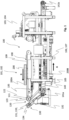
- the system 100 comprises a first section 101 forming a handling and turning arrangement 102 and an optional second section 103 forming a cutting arrangement 104.
- the second section 103 is arranged downstream the first section 101 and the two sections are arranged in communication with each other via a lower conveyor 105 that extends between the two sections.
- the lower conveyor 105 has a feeding direction as illustrated by arrow A.
- the first section 101 comprises a frame 106 supported by legs 107.
- the frame 106 supports an upper conveyor 108 that comprises four parallel sub-conveyors 109 in the form of chain-conveyors.
- Each sub-conveyor 109 is supported by a first and a second driving wheel 110a, 110b.
- the first driving wheels 110a are supported and/or driven by a common motor driven shaft 111. All sub-conveyors 109 may thereby operate at the same speed.
- the upper conveyor 108 is preferably continuously driven.
- the invention should not be limited to the type of conveyor or the number of sub-conveyors used.
- the sub-conveyors 109 have a feeding direction as illustrated by arrow B in Fig. 1 .
- the feeding direction of the upper conveyor 108 is accordingly opposite the feeding direction of the lower conveyor 105.
- the upper surface 112 of the upper conveyor 108 is configured to receive a package of studs 200 (schematically disclosed) arranged edgeways side by side in an abutting relation with their longitudinal extensions extending transverse the feeding direction of the upper conveyor 108.
- the package of studs 200 represents a single layer of studs that may be picked by a robot gripper (not disclosed), such as a vacuum plate from a pallet of studs (not disclosed).
- a separating arrangement 120 is arranged adjacent the downstream end of the upper conveyor 108.
- the separating arrangement 120 comprises a set of sensors 121 configured to detect if a stud (200A, 200B) is approaching.
- the sensors 121 may by the way of example be photo sensors or laser sensors.
- the separating arrangement 120 further comprises a reciprocating projection 122 which is arranged in a fixed position adjacent each sub-conveyor 109. The reciprocation may be provided by using non disclosed pistons or using a cam shaft.
- the separating arrangement 120 comprises a plurality of wheels 123 which are arranged on the same shaft 110a that drives the upper conveyor 108. Each wheel 123 has a larger diameter than the driving wheel 111a of the upper conveyor 108. Thereby, the peripheral velocity of the wheels 123 will be higher than the driving wheels 111a of the upper conveyor 108.
- the separating arrangement 120 comprises a plurality of lifting blocks 124 which are movable in the vertical direction by non-disclosed pistons.
- the sensors 121 will detect the same and provide a signal to a non-disclosed control unit.
- the control unit is configured to set the projections 122 to a position in which they project in the vertical direction transverse the path of the upper conveyor 108.
- the control unit is configured to set the lifting blocks 124 into a vertically lifted position whereby at least the first stud 200A in the package of studs 200 is raised to a clearance position above the upper conveyor 108.
- the leading stud 200A will thereby come in contact with the wheels 123.
- the leading stud 200A will be accelerated and hence be separated from the remaining studs in the package of studs 200.
- the projection 122 is returned to its lowered position. Accordingly, one stud 200B at the time will be allowed to leave the upper conveyor 108 and fall own onto the lower conveyor 105.
- the lifting blocks 124 are then lowered whereby the package of studs 200 comes in contact with the upper conveyor 108 anew and is moved forward. This process is repeated as long as there are any studs remaining in the package 200.
- the studs 200B will be arranged on the lower conveyor 105 with a longitudinal mutual distance to each other.
- the system 100 further comprises a guide arrangement 130 that is arranged downstream the upper conveyor 108 in a position between the upper and the lower conveyors 108, 105.
- the guide arrangement 130 comprises a first set of guiding arms 131, with one guiding arm adjacent each sub-conveyor 109 of the upper conveyor 108.
- Each guiding arm 131 is pivotable attached to the frame 106 adjacent the lower conveyor 105 and forms an angle thereto.
- a substantially vertically acting piston 132 operates the guiding arms 131 to be adjustable in a direction towards the upper conveyor 108.
- each guiding arm 131 in the first set is provided with a conveyor belt 133 having a feeding direction (arrow C) towards the lower conveyor 105.
- the guide arrangement 130 further comprises a second set of guiding arms 134 which are pivotably attached to the frame 106 adjacent the upper conveyor 108 and forms and angle thereto.
- a substantially horizontally acting piston 135 operates the guiding arms 134 to be movable in a direction towards the guiding arms 131 of the first set.
- the purpose of the guide arrangement 130 is to guide the stud 200A which leaves the upper conveyor 108 so that it falls to the lower conveyor 105 in a controlled manner held between the first and second sets of guiding arms 131,134 without rolling over.
- the stud 200B has changed orientation when entering the lower conveyor 105 so that instead of being standing edgeways it is lying down.
- the separated studs 200B are schematically illustrated on the lower conveyor 105.
- the lower conveyor 105 comprises in the disclosed embodiment three parallel sub-conveyors 140. Each sub-conveyor 140 is supported by a first and a second driving wheel 141a, 141b. In the disclosed embodiment the second driving wheels 141b are motor driven. The lower conveyor 105 is preferably continuously driven.
- the sub-conveyors are disclosed as chain-conveyors. The invention should not be limited to the type of conveyor or the number of sub-conveyors used.
- An optional positioning arrangement 150 may be arranged adjacent the upstream end of the lower conveyor 105.
- the positioning arrangement 150 comprises a rotatable projection 151 which is arranged adjacent each sub-conveyor 140.
- each projection 151 is configured to be set to a position in which it projects transverse the path of the lower conveyor 105, see dashed lines.
- any misalignment of the stud 200B will be corrected by the leading end of the stud 200B being temporarily stopped. Since the stud 200B as a whole is fed by a plurality of sub-conveyors 140, the stud 200A will automatically align by turning into a direction perpendicularly to the feeding direction of the lower conveyor 105.
- a sensor arrangement 160 is arranged downstream the positioning arrangement 150, see Figs. 2 and 4A-4B .
- the sensor arrangement 160 is configured to measure the curvature of the stud 200B as seen along its longitudinal extension and as seen in a major plane of the lower conveyor 105.
- the sensor arrangement 160 comprises in the disclosed embodiment, see Figs 4A and 4B , an array of three sensors 161a-161c.
- One sensor is arranged adjacent each sub-conveyor 140.
- the sensors 161a-161c are directed upwards to thereby be able to detect a stud 200B that passes over the sensor arrangement.
- the individual sensors 161a-161c are arranged on a distance from each other and distributed along a virtual line L that extends transverse, i.e. perpendicular to the feeding direction of the lower conveyor 105.
- the sensors 161a-161c are arranged to communicate with a control unit to be discussed below.
- a stud 200B passing the array of sensors 161a-161c is schematically illustrated. In fig.
- each sensor 161a-161c indicates a positive signal, i.e. detection of a stud portion. This is an indication of that the stud 200B has an acceptable orientation and hence a correct curvature.
- Fig. 4B only one of the sensors161a-161c, the sensor 161b in the middle, indicates a positive signal, i.e. a detection of a stud portion. This may be used as an indication of an incorrect orientation which may be corrected by turning the stud 200B 180 degrees.
- the signals from the sensors 161a-161c are transmitted to the control unit which processes the information and further controls the operation of a turning arrangement to be discussed below.
- the sensor arrangement 160 may be an array of a plurality of sensors.
- the sensor arrangement 160 may comprise at least one sensor being any of a photocell, a laser sensor, a radar sensor, a pressure sensor or an image sensor.
- the sensor arrangement 160 may comprise a combination of two or more sensor types.
- the term "array" should be understood as a group of sensors which are arranged in determined pattern.
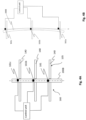
- the array may by way of example be a straight linear pattern with the sensors 161a-161c being arranged one after the other along a straight line L, see Figs. 5A .
- the array may be a pattern comprising several adjacent straight lines in which lines sensors 161a-161c are arranged one after the other, see Fig. 5B .
- the individual sensors 161a-161c are arranged on a distance from each other and distributed in a direction transverse the feeding direction of the lower conveyor 105.
- at least three sensors 161a-161c are provided. Thereby, in the event not all three sensors 161a-161c indicates a positive signal, i.e. a detection of a stud portion, this may be used as an indication of an incorrect orientation which may be corrected by turning the stud 200B 180 degrees.
- an array comprising several lines of sensors 161a-161c may be used to determine not only an incorrect orientation, but also to determine if the curvature is too curved. If too curved, it may be used as a signal of that the stud should be removed from the conveyor.
- Fig. 5C illustrates another example in which the sensor arrangement 160 uses a single image sensor 162 and where the curvature is determined by image analysis.
- the image sensor 162 such as camera may be arranged above the lower conveyor 105 to be able to monitor studs 200A passing on the lower conveyor 105.
- the image sensor has a working area schematically illustrated by dash-dotted lines.
- the image captured by the image sensor 162 is compared, by using the control unit, with pre-determined geometrical boundaries, illustrated by dashed lines, representing an acceptable orientation. If the orientation of the stud 200B is determined by the control unit to be non-acceptable, the stud 200B should be turned 180 degrees. This is made by the control unit communicating with and instructing the turning arrangement to be discussed below to turn the stud 200B.
- the system comprises a turning arrangement 170 which is arranged downstream the sensor arrangement 160.
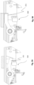
- the turning arrangement 170 comprises in the disclosed embodiment three pivotable arms 171 (only one arm being disclosed in Fig. 2 ), where each arm 171 is pivotably attached to the frame 106 in a position below an adjacent sub-conveyor 140.
- the pivotable arm 171 has a curved extension with a finger 172 in its free end.
- Each pivotable arm 171 is configured to be movable from a resting position, see Fig. 6A in which the arm 171 has no contact with the stud 200B, into an engagement position, see Fig.
- the turning arrangement 170 is configured to be operated based on instructions from the control unit related to the sensor arrangement 160. Accordingly, the turning arrangement 170 is configured to be operated only in the event the stud 200A approaching the turning arrangement 170 has been determined by using the sensor arrangement 160 to have a non-acceptable curvature. Otherwise the stud 200A should be allowed to pass.
- the system comprising a sensor arrangement 160, a control unit and a turning arrangement 170
- all studs passing the turning arrangement 170 on the lower conveyor 105 will be oriented into one and the same orientation.
- the system may be seen as a screening system that sorts and orients arbitrary arranged single-curved studs into one and the same orientation where all studs are oriented side by side with a convex longitudinal edge of a first stud facing a concave longitudinal edge of a subsequent stud.
- the system further comprises a cutting arrangement 180, see Fig. 2 .
- the cutting arrangement 180 is arranged downstream the lower conveyor 105 and is configured to cut at least one of the two free ends of the stud 200B. It is preferred that both free ends of the stud 200B are cut. One end may be cut to provide a clean cut, whereas the other end may be used to cut the stud 200B to a pre-set length.
- the cutting arrangement 180 comprises two cutting machines 181.
- the cutting machines 181 may by way of example be circular saws having disc saw blades (not disclosed) encapsulated in protective housings 182.
- the cutting machines 181 are arranged in parallel with the longitudinal extension of the lower conveyor 105, i.e. one at each end of the stud 200B. Before cutting the free ends, the stud 200B may be pushed in its longitudinal direction towards a non-disclosed anvil. It is preferred that at least one of the cutting machines 181 is movable in a direction transverse the feeding direction of the lower conveyor 105 to thereby set the system to cut studs to a pre-set length.
- this is made by one of the cutting machines 181 being movable along rails 183a, 183b extending transverse the lower conveyor 105.
- the movement of the cutting machines 181 in view of each other may be made based on information communicated directly to the control unit from a CAD model representing a building module, such as a frame wall in which the stud later is to be used.
- Fig. 7 a method of orienting a plurality of studs 200A into one and the same curvature based orientation will be disclosed.
- the method comprises the following acts: Arranging a package of studs 200 on an upper conveyor 108.
- Measuring 2000 by using a sensor arrangement 160, the curvature of the stud 200A as seen along its longitudinal extension and as seen in a major plane of the conveyor.
- Determining 3000 based on input from said measuring, whether or not the stud 200A has an acceptable curvature as seen along its longitudinal extension and as seen in a major plane of the conveyor.
- the act of determining whether or not the stud 200A has an acceptable curvature may comprise receiving, by a control unit, a signal from the sensor arrangement 160; determining whether or not the stud 200A has an acceptable curvature as seen along its longitudinal extension and as seen in the major plane of the conveyor; and instructing the turning arrangement 170 to turn the stud 200A 180 degrees around its longitudinal extension if it is determined that the stud 200A has a non-acceptable curvature.
- the act of turning the stud 200A may comprise moving at least one pivotable arm 171 from a resting position in which it has no contact with the stud 200A into a turning position in which it engages and lifts a first longitudinal edge portion of the stud 200A to such extent that the stud 200A is turned 180 degrees around its longitudinal extension.
- control unit may be used to control the full system and especially the operation of one or more of the separating arrangement 120, the guide arrangement 130, the positioning arrangement 150, the sensor arrangement 160, the turning arrangement 170 and the cutting arrangement 180.
Landscapes
- Engineering & Computer Science (AREA)
- Mechanical Engineering (AREA)
- Life Sciences & Earth Sciences (AREA)
- Forests & Forestry (AREA)
- Biodiversity & Conservation Biology (AREA)
- Wood Science & Technology (AREA)
- Attitude Control For Articles On Conveyors (AREA)
Claims (8)
- Système configuré pour orienter une pluralité de goujons dans une seule et même orientation basée sur la courbure, le système comprenant :un convoyeur supérieur (108) ayant une direction d'alimentation et comprenant une surface supérieure (112) configurée pour recevoir un paquet de goujons (200) ;un agencement de séparation (120) configuré pour permettre à un goujon (200A, 200B) à la fois d'être alimenté sur un convoyeur inférieur (105) à partir du paquet de goujons (200) avec une distance mutuelle les uns par rapport aux autres ;le convoyeur inférieur (105) ayant une direction d'alimentation (A) opposée à la direction d'alimentation du convoyeur supérieur (108) et étant agencé pour recevoir le goujon (200A, 200B) orienté avec son extension longitudinale dans une direction transversale à la direction d'alimentation ;un agencement de capteurs (160) configuré pour mesurer la courbure du goujon (200A, 200B) telle qu'observée selon son extension longitudinale et telle qu'observée dans un plan principal du convoyeur inférieur (105) ; etun agencement de rotation (170) configuré pour faire tourner le goujon (200A, 200B) de 180 degrés autour de son extension longitudinale,dans lequell'agencement de rotation (170) comprend au moins un bras pivotant (171) configuré pour être mobile d'une position de repos dans laquelle il n'a aucun contact avec le goujon (200A, 200B) à une position de rotation dans laquelle il s'engage avec une première portion de bord longitudinale du goujon (200A, 200B) et la soulève de telle sorte que le goujon (200A, 200B) est tourné de 180 degrés autour de son extension longitudinale.
- Système selon la revendication 1, dans lequel l'agencement de capteurs (160) comprend au moins un capteur (161a-161c) qui est une cellule photoélectrique, un capteur laser, un capteur radar, un capteur de pression ou un capteur d'image.
- Système selon la revendication 1 ou 2, dans lequel l'agencement de capteurs (160) est un réseau d'une pluralité de capteurs (161a-161c).
- Système selon l'une quelconque des revendications précédentes, comprenant en outre une unité de commande, l'unité de commande étant configurée pour recevoir un signal provenant de l'agencement de capteurs (160) ; pour déterminer si le goujon (200A, 200B) présente ou non une courbure acceptable telle qu'observée selon son extension longitudinale et telle qu'observée dans le plan principal du convoyeur (105) ; et pour commander à l'agencement de rotation (170) de faire tourner le goujon (200A, 200B) s'il est déterminé que le goujon (200A, 200B) présente une courbure non acceptable.
- Système selon l'une quelconque des revendications précédentes, comprenant en outre un agencement de coupe (180) configuré pour couper au moins l'une des deux extrémités libres du goujon (200A, 200B).
- Procédé d'orientation d'une pluralité de goujons dans une même orientation basée sur la courbure, comprenant les étapes suivantes :agencement d'un paquet de goujons (200) sur un convoyeur supérieur (108) ayant une direction d'alimentation ;séparation, en utilisant un agencement de séparation (120), de la pluralité de goujons (200A, 200B) agencés dans le paquet de goujons (200), permettant ainsi à un goujon (200A, 200B) à la fois d'être alimenté sur un convoyeur inférieur (105) avec une distance mutuelle les uns par rapport aux autres ;positionnement (1000) du goujon (200A, 200B) sur le convoyeur inférieur (105) avec une extension longitudinale du goujon (200A, 200B) orientée dans une direction transversale à une direction d'alimentation (A) du convoyeur inférieur (105), dans lequel la direction d'alimentation du convoyeur inférieur (105) est opposée à la direction d'alimentation du convoyeur supérieur (108) ;mesure (2000), en utilisant un agencement de capteurs (160), de la courbure du goujon (200A, 200B) telle qu'observée selon son extension longitudinale et telle qu'observée dans un plan principal du convoyeur inférieur (105) ;détermination (3000), sur la base de l'entrée provenant de ladite mesure, du fait que le goujon (200A, 200B) présente ou non une courbure acceptable telle qu'observée selon son extension longitudinale et telle qu'observée dans un plan principal du convoyeur inférieur (105) ; ets'il est déterminé que le goujon (200A, 200B) présente une courbure non acceptable, rotation (4000) du goujon (200A, 200B) de 180 degrés autour de son extension longitudinale, dans lequel la rotation est effectuée en déplaçant au moins un bras pivotant (171) d'une position de repos dans laquelle il n'a aucun contact avec le goujon (200A, 200B) à une position de rotation dans laquelle il s'engage avec une première portion de bord longitudinale du goujon (200A, 200B) et la soulève de telle sorte que le goujon (200A, 200B) est tourné de 180 degrés autour de son extension longitudinale.
- Procédé selon la revendication 6, dans lequel l'étape consistant à déterminer (3000) si le goujon (200A, 200B) présente ou non une courbure acceptable comprend :la réception, par une unité de commande, d'un signal provenant de l'agencement de capteurs (160) ;la détermination du fait que le goujon (200A, 200B) présente ou non une courbure acceptable telle qu'observée selon son extension longitudinale et telle qu'observée dans le plan principal du convoyeur (105) ; etla commande à l'agencement de rotation (170) de faire tourner le goujon (200A, 200B) de 180 degrés autour de son extension longitudinale s'il est déterminé que le goujon (200A, 200B) présente une courbure non acceptable.
- Utilisation d'un système selon l'une quelconque des revendications 1 à 5 dans un établissement de fabrication de maisons préfabriquées.
Applications Claiming Priority (2)
| Application Number | Priority Date | Filing Date | Title |
|---|---|---|---|
| SE1850976A SE542989C2 (en) | 2018-08-14 | 2018-08-14 | A system to orient a plurality of studs into one and the same curvature based orientation, a use of such a system during prefabricated house manufacturing and a corresponding method of orienting a plurality of studs |
| PCT/EP2019/068807 WO2020035236A1 (fr) | 2018-08-14 | 2019-07-12 | Système et procédé d'orientation d'une pluralité de broches |
Publications (3)
| Publication Number | Publication Date |
|---|---|
| EP3837193A1 EP3837193A1 (fr) | 2021-06-23 |
| EP3837193C0 EP3837193C0 (fr) | 2024-10-09 |
| EP3837193B1 true EP3837193B1 (fr) | 2024-10-09 |
Family
ID=67352520
Family Applications (1)
| Application Number | Title | Priority Date | Filing Date |
|---|---|---|---|
| EP19742001.1A Active EP3837193B1 (fr) | 2018-08-14 | 2019-07-12 | Système et procédé d'orientation d'une pluralité de broches |
Country Status (5)
| Country | Link |
|---|---|
| US (1) | US11358806B2 (fr) |
| EP (1) | EP3837193B1 (fr) |
| AU (1) | AU2019320978A1 (fr) |
| SE (1) | SE542989C2 (fr) |
| WO (1) | WO2020035236A1 (fr) |
Families Citing this family (4)
| Publication number | Priority date | Publication date | Assignee | Title |
|---|---|---|---|---|
| CN113192752B (zh) * | 2021-03-29 | 2022-12-27 | 深圳市正达飞智能卡有限公司 | 智能卡绕线机 |
| CN114308724B (zh) * | 2021-12-25 | 2023-01-06 | 瑞安市朝阳标准件有限公司 | 一种螺杆检测设备 |
| AT526066B1 (de) * | 2022-09-09 | 2023-11-15 | Fill Gmbh | Holzlamellenhandlinganlage, sowie ein Verfahren zum Betreiben der Holzlamellenhandlinganlage |
| DE102023002012A1 (de) * | 2023-05-15 | 2024-11-21 | Weinig Grecon GmbH & Co. KG | Anlage zum Sortieren von Werkstücken aus Holz, Kunststoff und dergleichen |
Citations (2)
| Publication number | Priority date | Publication date | Assignee | Title |
|---|---|---|---|---|
| US6374714B1 (en) * | 1999-02-26 | 2002-04-23 | Silvatech Corporation | Combined grading and trimming method for sawmill |
| US20170057113A1 (en) * | 2010-09-02 | 2017-03-02 | Steven L. Aylsworth | Lumber Retrieval Method With Selective Crown Orientation |
Family Cites Families (11)
| Publication number | Priority date | Publication date | Assignee | Title |
|---|---|---|---|---|
| US3080042A (en) * | 1961-10-27 | 1963-03-05 | Weyerhaeuser Co | Lumber feeder for random lengths and widths |
| SE424282B (sv) | 1980-12-23 | 1982-07-12 | Hammars Mekaniska Verkstad Ab | Forfarande vid justering av virkesstycken jemte en anordning for utforande av forfarandet |
| US4484675A (en) * | 1982-12-13 | 1984-11-27 | U. S. Natural Resources, Inc. | Board turner apparatus and method capable of multiple turn inspection |
| US5605216A (en) | 1994-12-30 | 1997-02-25 | Hi-Tech Engineering Inc. | Board turning apparatus |
| US6431345B2 (en) * | 1999-06-23 | 2002-08-13 | U.S. Natural Resources, Inc. | High speed board feeder |
| CA2327601A1 (fr) * | 2000-12-05 | 2002-06-05 | 2635-5727 Quebec Inc. | Dispositif de retournement de bois d'oeuvre et de pieces semblables |
| CA2454986A1 (fr) | 2004-01-08 | 2005-07-08 | Martin Perreault | Systeme de tourne-pieces aleatoire |
| US8978872B2 (en) * | 2009-05-01 | 2015-03-17 | Baxley Equipment Co. | High speed board feeder |
| WO2014078939A1 (fr) | 2012-11-26 | 2014-05-30 | 381572 Ontario Limited (O/A Ts Manufacturing Company) | Appareil de transport de baguettes vers une pile de bois |
| WO2017083871A1 (fr) * | 2015-11-13 | 2017-05-18 | Usnr, Llc | Dispositif pour faire tourner des plaques |
| DE202017104924U1 (de) | 2017-08-16 | 2017-09-06 | Vemag Maschinenbau Gmbh | Vorrichtung zum Ausrichten von Würsten |
-
2018
- 2018-08-14 SE SE1850976A patent/SE542989C2/en unknown
-
2019
- 2019-07-12 WO PCT/EP2019/068807 patent/WO2020035236A1/fr not_active Ceased
- 2019-07-12 AU AU2019320978A patent/AU2019320978A1/en not_active Abandoned
- 2019-07-12 EP EP19742001.1A patent/EP3837193B1/fr active Active
- 2019-07-12 US US17/266,301 patent/US11358806B2/en active Active
Patent Citations (2)
| Publication number | Priority date | Publication date | Assignee | Title |
|---|---|---|---|---|
| US6374714B1 (en) * | 1999-02-26 | 2002-04-23 | Silvatech Corporation | Combined grading and trimming method for sawmill |
| US20170057113A1 (en) * | 2010-09-02 | 2017-03-02 | Steven L. Aylsworth | Lumber Retrieval Method With Selective Crown Orientation |
Also Published As
| Publication number | Publication date |
|---|---|
| SE542989C2 (en) | 2020-09-22 |
| AU2019320978A1 (en) | 2021-02-18 |
| EP3837193C0 (fr) | 2024-10-09 |
| EP3837193A1 (fr) | 2021-06-23 |
| WO2020035236A1 (fr) | 2020-02-20 |
| SE1850976A1 (en) | 2020-02-15 |
| US20210300688A1 (en) | 2021-09-30 |
| US11358806B2 (en) | 2022-06-14 |
Similar Documents
| Publication | Publication Date | Title |
|---|---|---|
| EP3837193B1 (fr) | Système et procédé d'orientation d'une pluralité de broches | |
| US5605216A (en) | Board turning apparatus | |
| CA1329908C (fr) | Dispositif d'amenee automatique pour scie a debit longitudinal multiple | |
| AU2019202149B2 (en) | Board turner | |
| US8281696B2 (en) | Linear feed cutting apparatus and method | |
| US11809894B2 (en) | Virtual autocalibration of sensors | |
| EP1896228B1 (fr) | Systeme automatique de coupe de precision de bois courbe | |
| CA2218171C (fr) | Systeme d'alimentation automatique | |
| US4462443A (en) | Positioning and feeding apparatus for lumber edger including improved clamp means | |
| US11964335B2 (en) | Method and apparatus for providing flitches to an edger | |
| US6240821B1 (en) | Dual positioning and orienting saw infeed apparatus | |
| US20170121123A1 (en) | Wood board feeding system with alignment feature | |
| US11958207B2 (en) | Method and apparatus for feeding an edger | |
| US20070039664A1 (en) | Saw infeed system | |
| US20040182214A1 (en) | Handling arrangement for sawing items | |
| US7870880B2 (en) | Optimizing planer infeed system and method | |
| US20070028729A1 (en) | Infeed system with automated workpiece orientation | |
| CA2567084A1 (fr) | Methode et dispositif de manutention de pieces profilees | |
| WO2003064299A1 (fr) | Appareil et procede d'alignement automatique |
Legal Events
| Date | Code | Title | Description |
|---|---|---|---|
| STAA | Information on the status of an ep patent application or granted ep patent |
Free format text: STATUS: UNKNOWN |
|
| STAA | Information on the status of an ep patent application or granted ep patent |
Free format text: STATUS: THE INTERNATIONAL PUBLICATION HAS BEEN MADE |
|
| PUAI | Public reference made under article 153(3) epc to a published international application that has entered the european phase |
Free format text: ORIGINAL CODE: 0009012 |
|
| STAA | Information on the status of an ep patent application or granted ep patent |
Free format text: STATUS: REQUEST FOR EXAMINATION WAS MADE |
|
| 17P | Request for examination filed |
Effective date: 20210208 |
|
| AK | Designated contracting states |
Kind code of ref document: A1 Designated state(s): AL AT BE BG CH CY CZ DE DK EE ES FI FR GB GR HR HU IE IS IT LI LT LU LV MC MK MT NL NO PL PT RO RS SE SI SK SM TR |
|
| DAV | Request for validation of the european patent (deleted) | ||
| DAX | Request for extension of the european patent (deleted) | ||
| STAA | Information on the status of an ep patent application or granted ep patent |
Free format text: STATUS: EXAMINATION IS IN PROGRESS |
|
| 17Q | First examination report despatched |
Effective date: 20220920 |
|
| GRAP | Despatch of communication of intention to grant a patent |
Free format text: ORIGINAL CODE: EPIDOSNIGR1 |
|
| STAA | Information on the status of an ep patent application or granted ep patent |
Free format text: STATUS: GRANT OF PATENT IS INTENDED |
|
| INTG | Intention to grant announced |
Effective date: 20231219 |
|
| GRAJ | Information related to disapproval of communication of intention to grant by the applicant or resumption of examination proceedings by the epo deleted |
Free format text: ORIGINAL CODE: EPIDOSDIGR1 |
|
| STAA | Information on the status of an ep patent application or granted ep patent |
Free format text: STATUS: EXAMINATION IS IN PROGRESS |
|
| GRAP | Despatch of communication of intention to grant a patent |
Free format text: ORIGINAL CODE: EPIDOSNIGR1 |
|
| STAA | Information on the status of an ep patent application or granted ep patent |
Free format text: STATUS: GRANT OF PATENT IS INTENDED |
|
| INTC | Intention to grant announced (deleted) | ||
| INTG | Intention to grant announced |
Effective date: 20240516 |
|
| GRAS | Grant fee paid |
Free format text: ORIGINAL CODE: EPIDOSNIGR3 |
|
| GRAA | (expected) grant |
Free format text: ORIGINAL CODE: 0009210 |
|
| STAA | Information on the status of an ep patent application or granted ep patent |
Free format text: STATUS: THE PATENT HAS BEEN GRANTED |
|
| AK | Designated contracting states |
Kind code of ref document: B1 Designated state(s): AL AT BE BG CH CY CZ DE DK EE ES FI FR GB GR HR HU IE IS IT LI LT LU LV MC MK MT NL NO PL PT RO RS SE SI SK SM TR |
|
| REG | Reference to a national code |
Ref country code: CH Ref legal event code: EP |
|
| REG | Reference to a national code |
Ref country code: DE Ref legal event code: R096 Ref document number: 602019060079 Country of ref document: DE |
|
| REG | Reference to a national code |
Ref country code: IE Ref legal event code: FG4D |
|
| U01 | Request for unitary effect filed |
Effective date: 20241023 |
|
| U07 | Unitary effect registered |
Designated state(s): AT BE BG DE DK EE FI FR IT LT LU LV MT NL PT RO SE SI Effective date: 20241106 |
|
| PG25 | Lapsed in a contracting state [announced via postgrant information from national office to epo] |
Ref country code: IS Free format text: LAPSE BECAUSE OF FAILURE TO SUBMIT A TRANSLATION OF THE DESCRIPTION OR TO PAY THE FEE WITHIN THE PRESCRIBED TIME-LIMIT Effective date: 20250209 Ref country code: HR Free format text: LAPSE BECAUSE OF FAILURE TO SUBMIT A TRANSLATION OF THE DESCRIPTION OR TO PAY THE FEE WITHIN THE PRESCRIBED TIME-LIMIT Effective date: 20241009 |
|
| PG25 | Lapsed in a contracting state [announced via postgrant information from national office to epo] |
Ref country code: ES Free format text: LAPSE BECAUSE OF FAILURE TO SUBMIT A TRANSLATION OF THE DESCRIPTION OR TO PAY THE FEE WITHIN THE PRESCRIBED TIME-LIMIT Effective date: 20241009 |
|
| PG25 | Lapsed in a contracting state [announced via postgrant information from national office to epo] |
Ref country code: NO Free format text: LAPSE BECAUSE OF FAILURE TO SUBMIT A TRANSLATION OF THE DESCRIPTION OR TO PAY THE FEE WITHIN THE PRESCRIBED TIME-LIMIT Effective date: 20250109 |
|
| PG25 | Lapsed in a contracting state [announced via postgrant information from national office to epo] |
Ref country code: GR Free format text: LAPSE BECAUSE OF FAILURE TO SUBMIT A TRANSLATION OF THE DESCRIPTION OR TO PAY THE FEE WITHIN THE PRESCRIBED TIME-LIMIT Effective date: 20250110 |
|
| PG25 | Lapsed in a contracting state [announced via postgrant information from national office to epo] |
Ref country code: PL Free format text: LAPSE BECAUSE OF FAILURE TO SUBMIT A TRANSLATION OF THE DESCRIPTION OR TO PAY THE FEE WITHIN THE PRESCRIBED TIME-LIMIT Effective date: 20241009 |
|
| PG25 | Lapsed in a contracting state [announced via postgrant information from national office to epo] |
Ref country code: RS Free format text: LAPSE BECAUSE OF FAILURE TO SUBMIT A TRANSLATION OF THE DESCRIPTION OR TO PAY THE FEE WITHIN THE PRESCRIBED TIME-LIMIT Effective date: 20250109 |
|
| PG25 | Lapsed in a contracting state [announced via postgrant information from national office to epo] |
Ref country code: SM Free format text: LAPSE BECAUSE OF FAILURE TO SUBMIT A TRANSLATION OF THE DESCRIPTION OR TO PAY THE FEE WITHIN THE PRESCRIBED TIME-LIMIT Effective date: 20241009 |
|
| PGFP | Annual fee paid to national office [announced via postgrant information from national office to epo] |
Ref country code: GB Payment date: 20250613 Year of fee payment: 7 |
|
| U20 | Renewal fee for the european patent with unitary effect paid |
Year of fee payment: 7 Effective date: 20250613 |
|
| PG25 | Lapsed in a contracting state [announced via postgrant information from national office to epo] |
Ref country code: SK Free format text: LAPSE BECAUSE OF FAILURE TO SUBMIT A TRANSLATION OF THE DESCRIPTION OR TO PAY THE FEE WITHIN THE PRESCRIBED TIME-LIMIT Effective date: 20241009 |
|
| PG25 | Lapsed in a contracting state [announced via postgrant information from national office to epo] |
Ref country code: CZ Free format text: LAPSE BECAUSE OF FAILURE TO SUBMIT A TRANSLATION OF THE DESCRIPTION OR TO PAY THE FEE WITHIN THE PRESCRIBED TIME-LIMIT Effective date: 20241009 |
|
| PLBE | No opposition filed within time limit |
Free format text: ORIGINAL CODE: 0009261 |
|
| STAA | Information on the status of an ep patent application or granted ep patent |
Free format text: STATUS: NO OPPOSITION FILED WITHIN TIME LIMIT |
|
| 26N | No opposition filed |
Effective date: 20250710 |
|
| REG | Reference to a national code |
Ref country code: CH Ref legal event code: H13 Free format text: ST27 STATUS EVENT CODE: U-0-0-H10-H13 (AS PROVIDED BY THE NATIONAL OFFICE) Effective date: 20260224 |
|
| PG25 | Lapsed in a contracting state [announced via postgrant information from national office to epo] |
Ref country code: CH Free format text: LAPSE BECAUSE OF NON-PAYMENT OF DUE FEES Effective date: 20250731 |