EP3837485B1 - Vorrichtung - Google Patents
Vorrichtung Download PDFInfo
- Publication number
- EP3837485B1 EP3837485B1 EP19718629.9A EP19718629A EP3837485B1 EP 3837485 B1 EP3837485 B1 EP 3837485B1 EP 19718629 A EP19718629 A EP 19718629A EP 3837485 B1 EP3837485 B1 EP 3837485B1
- Authority
- EP
- European Patent Office
- Prior art keywords
- heat transfer
- transfer element
- heat
- cooling
- devices
- Prior art date
- Legal status (The legal status is an assumption and is not a legal conclusion. Google has not performed a legal analysis and makes no representation as to the accuracy of the status listed.)
- Active
Links
Images






Classifications
-
- F—MECHANICAL ENGINEERING; LIGHTING; HEATING; WEAPONS; BLASTING
- F28—HEAT EXCHANGE IN GENERAL
- F28F—DETAILS OF HEAT-EXCHANGE AND HEAT-TRANSFER APPARATUS, OF GENERAL APPLICATION
- F28F13/00—Arrangements for modifying heat-transfer, e.g. increasing, decreasing
-
- H—ELECTRICITY
- H10—SEMICONDUCTOR DEVICES; ELECTRIC SOLID-STATE DEVICES NOT OTHERWISE PROVIDED FOR
- H10W—GENERIC PACKAGES, INTERCONNECTIONS, CONNECTORS OR OTHER CONSTRUCTIONAL DETAILS OF DEVICES COVERED BY CLASS H10
- H10W40/00—Arrangements for thermal protection or thermal control
- H10W40/10—Arrangements for heating
-
- H—ELECTRICITY
- H10—SEMICONDUCTOR DEVICES; ELECTRIC SOLID-STATE DEVICES NOT OTHERWISE PROVIDED FOR
- H10W—GENERIC PACKAGES, INTERCONNECTIONS, CONNECTORS OR OTHER CONSTRUCTIONAL DETAILS OF DEVICES COVERED BY CLASS H10
- H10W40/00—Arrangements for thermal protection or thermal control
- H10W40/20—Arrangements for cooling
- H10W40/25—Arrangements for cooling characterised by their materials
- H10W40/255—Arrangements for cooling characterised by their materials having a laminate or multilayered structure, e.g. direct bond copper [DBC] ceramic substrates
-
- H—ELECTRICITY
- H10—SEMICONDUCTOR DEVICES; ELECTRIC SOLID-STATE DEVICES NOT OTHERWISE PROVIDED FOR
- H10W—GENERIC PACKAGES, INTERCONNECTIONS, CONNECTORS OR OTHER CONSTRUCTIONAL DETAILS OF DEVICES COVERED BY CLASS H10
- H10W40/00—Arrangements for thermal protection or thermal control
- H10W40/40—Arrangements for thermal protection or thermal control involving heat exchange by flowing fluids
- H10W40/47—Arrangements for thermal protection or thermal control involving heat exchange by flowing fluids by flowing liquids, e.g. forced water cooling
-
- F—MECHANICAL ENGINEERING; LIGHTING; HEATING; WEAPONS; BLASTING
- F28—HEAT EXCHANGE IN GENERAL
- F28F—DETAILS OF HEAT-EXCHANGE AND HEAT-TRANSFER APPARATUS, OF GENERAL APPLICATION
- F28F13/00—Arrangements for modifying heat-transfer, e.g. increasing, decreasing
- F28F2013/005—Thermal joints
-
- F—MECHANICAL ENGINEERING; LIGHTING; HEATING; WEAPONS; BLASTING
- F28—HEAT EXCHANGE IN GENERAL
- F28F—DETAILS OF HEAT-EXCHANGE AND HEAT-TRANSFER APPARATUS, OF GENERAL APPLICATION
- F28F13/00—Arrangements for modifying heat-transfer, e.g. increasing, decreasing
- F28F2013/005—Thermal joints
- F28F2013/006—Heat conductive materials
Definitions
- the invention relates to a device comprising a first device and a second device, wherein the first device is a heat source and wherein the second device is a cooling device, wherein the second device absorbs heat emitted by the first device, wherein a heat transfer element is arranged between the first device and the second device.
- the US 2007/0177356 A1 shows a device comprising a heat source and a cooling device.
- a heat transfer element is arranged between the heat source and the cooling device and is connected to the cooling device.
- the US 4,029,999 shows a device that includes a heat source and a cooling device.
- the side of the heat transfer element facing the heat source has recesses in order to spatially surround the heat-generating components of the heat source.
- a heat transfer element detachably connected to the cooling device is arranged between the heat source and the cooling device.
- the invention is based on the object of further developing a device with a heat-emitting device and a cooling device in such a way that good thermal conductivity is provided between the devices, while at the same time being simple and cost-effective to manufacture.
- the device for solving the problem comprises a first device and a second device, wherein the first device is a heat source and wherein the second device is a cooling device, wherein the second device absorbs heat emitted by the first device, wherein a heat transfer element is arranged between the first device and the second device, wherein the heat transfer element is molded onto the first device or the second device.
- the heat transfer element according to the invention is therefore a molded body, wherein the molded body is shaped at the same time as the heat transfer element is attached to the first device or the second device. This creates a heat transfer element with a shape adapted to the device.
- the heat transfer element can be molded either onto the heat-emitting first device or onto the cooling second device.
- the first device which forms the heat-emitting device, can be, for example, a component of an electronic component, a power electronics system, a sensor, an electrical connection, a battery or the like.
- the second device which is a cooling device, can be, for example, a thick-walled heat sink, a heat sink with cooling fins, a cooling channel through which liquid flows or media flows, a Peltier element or the like.
- the first device is tempered by the second device. If the device is exposed to the environment, it may be necessary to heat the first device at very low ambient temperatures. This can be done by the second device.
- the second device can generally be a device for tempering the first device. At low ambient temperatures, the first device is heated. At higher temperatures or when an operating temperature is reached, the first device is cooled.
- the heat transfer element is elastic.
- the elastic design of the heat transfer element ensures full-surface contact between the heat transfer element and the device on which the heat transfer element is placed. Direct surface contact is ensured by the direct molding of the heat transfer element onto a device.
- the elastic structure also means that the heat transfer element can adapt to surface irregularities or roughness, so that a flat form fit is also ensured at a microscopic level.
- the heat transfer element is molded directly onto a device, the heat transfer element is also firmly connected to this device. This ensures that it cannot be lost and reduces the number of assembly steps.
- the heat transfer element that is attached to one device can have a shape that is adapted to the other device.
- the heat transfer element therefore forms a receptacle for the other device, which on the one hand means particularly good heat transfer and on the other hand also simplifies production.
- the heat transfer element can have recesses for accommodating the device, to which the heat transfer element is not directly molded.
- the other device is not only in contact with the heat transfer element over its entire surface or on one side, but rather there is a large contact area between the other device and the heat transfer element, which further improves heat transport.
- the device is protected from external influences, such as vibrations, mechanical shocks, contamination and - if completely enclosed - also against the ingress of fluids by being embedded in the recess.
- the heat transfer element is made of injection-moldable material.
- the material of the heat transfer element is in liquid form and is applied to the device under high pressure.
- even fine contours of the device are filled so that there is surface contact over the entire surface, even at a microscopic level.
- thermally insulating gas bubbles that form an electrical leakage path occur between the device and the heat transfer element.
- elastomeric materials or thermoplastic elastomers are suitable for the heat transfer element. These materials have elastic properties and enable full-surface contact between the two devices.
- the material of the heat transfer element can contain thermally conductive particles. Such particles are, for example, graphite particles.
- the thermal conductivity of the material of the heat transfer element is preferably at least 0.5 W/(m ⁇ K).
- the material of the heat transfer element can comprise other thermally conductive and electrically insulating particles.
- Such particles are, for example, mineral oxides, such as aluminum oxide (Al 2 O 3 ), hydroxides such as aluminum hydroxide (Al(OH) 3 ) or nitrides, such as boron nitride (BN).
- the device to which the heat transfer element is molded can be made of metallic material.
- devices made of aluminum or copper are particularly suitable. These materials have a particularly high thermal conductivity.
- the heat transfer element, which is molded directly onto the device, ensures a particularly high heat transfer.
- the device on which the heat transfer element is arranged can be made of plastic.
- the plastic is preferably an injection-moldable plastic.
- the use of a plastic results in weight advantages and simplified manufacturability.
- the material of the device can be provided with heat-conducting particles, for example graphite particles.
- the thermal conductivity of the device made of plastic is preferably at least 0.5 W/(m ⁇ K).
- the device is preferably the cooling device and the heat transfer element is molded directly onto the cooling device.
- a particularly cost-effective manufacturing process and a particularly good bond between the device and the heat transfer element are achieved when the device is made of two-component injection molding with an integral heat transfer element.
- the figures show a device 1 with a first device 2 and a second device 3.
- the first device 2 is a heat source, in particular an electronic component that emits heat.
- the first device 2 can be an accumulator, a component from microelectronics, a component of power electronics, for example a busbar, a capacitor, a power module, a transistor, a MOSFET, a bipolar transistor (IGBT) or the like.
- the second device 3 is a cooling device and can be designed, for example, as a metallic heat sink with cooling fins, as a cooling channel through which liquid flows, as a Peltier element or the like. If the device 3 is a channel through which liquid flows, the cooling medium, for example water, This can be water glycol, an oil or a medium known from air conditioning technology such as CO 2 , R1234yf or ammonia.
- a heat transfer element 4 is arranged between the first device 2 and the second device 3.
- the heat transfer element 4 is formed either onto the first device 2 or onto the second device 3.
- FIG. 1 shows a first embodiment of the device 1.
- the heat transfer element 4 is molded directly onto the second device 3, which forms the cooling device.
- the second device 3 is a passive cooling element which consists of a metallic material and is provided with cooling fins.
- the cooling fins are formed from the second device 3 on the side facing away from the first device 2.
- the heat transfer element 4 lies flat on the second device 3.
- the heat transfer element 4 is elastic, consists of an elastomeric material and is molded directly onto the second device 3 by means of injection molding. The heat transfer element 4 is thus integrally connected to the second device 3.
- first devices 2 are arranged on the side of the heat transfer element 4 facing away from the second device 3.
- the first devices 2 are electrical components that emit heat during operation.
- the first devices 2 lie flat on the heat transfer element 4 and transfer the heat via the heat transfer element 4 to the second device 3.
- the second device 3 emits the absorbed heat to the environment.
- the heat transfer element 4 consists of a thermally conductive silicone elastomer and has a thermal conductivity of 1.5 W/(m ⁇ K).
- the thermally conductive silicone elastomer is provided with thermally conductive fillers, present in the form of aluminum oxide (Al 2 O 3 ).
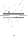
- FIG. 2 shows a further education of the Figure 1 shown device 1.
- the second device 3 is designed as a cooling channel.
- the second device is designed as a rectangular channel and has a directly molded heat transfer element 4 on one side, on which in turn the first devices 2 are arranged.
- the heat emitted by the first devices 2 is introduced into the second device 3 via the heat transfer element 4 and is then released to the cooling medium transported there.
- Cooling media can be, for example, liquid media such as water or a water/glycol mixture.
- the cooling media can be selected so that they undergo a phase transition during the cooling process. These are, for example, cooling media known from air conditioning technology such as R1234yf, ammonia, CO 2 or alkanes. Media that evaporate in the device without pressure and media that are passed through the arrangement in a supercritical state are also conceivable.
- the wall of the second device 3 opposite the heat transfer element 4 can be made of the same material as the wall facing the heat transfer element 4 or of a different material.
- the second device 3 consists of an injection-moldable plastic.
- the thermoplastic material of the second device 3 is provided with thermally conductive particles in the form of graphite particles.
- the second device 3 and the heat transfer element 4 were manufactured together by two-component injection molding.
- Figure 3 shows a further development of the Figure 1 shown device 1.
- the first devices 2 have different heights relative to the second device 3 due to their design.
- not all first devices 2 have the same dimensions.
- the heat transfer element 4 therefore has a shape adapted to the first devices 2.
- the heat transfer element 4 is molded directly onto the second device 3, the shaping being carried out in such a way that the arrangement of the first devices 3 and their dimensions are taken into account. After the assembly of the first devices 2 or the second device 3 with the heat transfer element 4, there is full-surface contact between the first devices 2, the heat transfer element 4 and the second device 3.
- Figure 4 shows a further education of the Figure 3 device shown 1.
- the heat transfer element 4 which is assigned to the first device 2 arranged in section A, has a recess 5 for receiving the first device 2. This improves heat dissipation, since the heat transfer element 4 also rests against the side surfaces of the first device 2.
- the heat transfer element 4 forms a protective device in which the first device 2 is at least partially embedded.
- the first device 2 which is arranged in section B, has an inclination relative to the second device 3.
- the heat transfer element 4 has a shape adapted to the first device 2.
- the first device 2 arranged in section C is partially embedded in the second device 3.
- a recess is made in the second device 3, which accommodates the heat transfer element 4 and partially the first device 2.
- the first device arranged in section D is at least partially embedded in the heat transfer element 4.
- the heat transfer element 4 has a recess 5.
- the heat transfer element 4 is in turn arranged in a recess made in the second device 3.
- the position of the first device 2 is such that the heat transfer element 4 is arranged completely in a recess of the second device 3.
- the heat transfer element 4 in turn has a recess 5 for receiving the first device 2.
- an opening 6 is made in the second device 3 so that the heat transfer element 4 can come into direct contact with a cooling medium.
- a recess 5 is made in the heat transfer element 4, which at least partially accommodates the first device 2.
- FIG. 5 shows various designs of heat transfer elements 4.
- the heat transfer elements 4 truncated pyramid shape. This shape is advantageous with regard to mechanical stress in the transverse direction.
- Figure 6 shows a further education of the Figure 4 shown device 1.
- the second device 3 is provided with cooling fins, wherein cooling fins 7 can also be formed directly from the heat transfer element 4, which are in contact with a cooling medium.
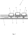
- FIG 7 shows a further education of the Figure 6 shown device 1.
- the heat transfer element 4 is designed as a sealing element.
- the heat transfer element 4 seals the second device 3, which is designed as a cooling channel, against the counter surface.
- the heat transfer element 4 can be arranged in the force shunt or in the force main connection. Additional mechanical anchoring by introducing undercuts of the heat transfer element 4 on the underside of the second device 3 offers advantages in the case of stress in the tensile direction
- Figure 8 shows a further education of the Figure 1 shown device 1.
- the second device 3 is provided with channels through which a cooling medium can flow.
- a turbulent flow and a high cooling capacity are achieved inside.
- the sealing of the channels can be achieved, for example, by applying a cover film.
- Figure 9 shows a further education of the Figure 1 shown device 1.
- a conducting element 8 is arranged between the heat transfer element 4 and the second device 3.
- the conducting element 8 distributes the heat emitted by the first devices 2 over the entire surface of the second device 3.
- the conducting element 8 can be made of metallic material or made of graphite and in the form of a plate or a foil.
- Figure 10 shows a further education of the Figure 9 shown device 1.
- the guide elements 8 are designed as insert elements and integrated into the second device 3.
- metallic components are particularly conceivable.
- Figure 11 shows a further education of the Figure 1 shown device 1.
- the second device 3 is provided with a macroscopic structure with structure depths between 10 and 1,000 ⁇ m on the side facing the cooling medium. This increases the surface and thus improves the heat transfer.
- a microscopic structure with structure depths of up to 10 ⁇ m can be provided.
- Another possibility is to provide the interface of the second device 3 in the direction of the cooling medium with a coating.
- Figure 12 shows a further education of the Figure 1 shown device 1.
- an additional layer 9, which is electrically conductive is applied to the side of the second device 3 facing away from the heat transfer element 4.
- the additional layer 9 can be applied to the second device 3 in the form of a coating.
- the additional layer 9 can be designed as an electrically conductive film, electrically conductive fabric, electrically conductive mesh or electrically conductive nonwoven fabric and can be attached to the second device 3.
- the additional layer 9 can provide electromagnetic shielding for the first devices 2. If the device 1 is designed as a direct current-alternating current inverter, for example, an emission of electromagnetic radiation from the first devices 2 can be avoided. If the device 1 is a battery management system according to another example the first devices 2 can be protected from electromagnetic radiation arriving from outside.
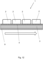
- Figure 13 shows a further development of the Figure 3 shown device 1, wherein the interface between the heat transfer element 4 and the second device 3 in the molding area does not have a planar configuration. This is particularly advantageous in mechanically stressed applications and for improved heat transfer. Such a configuration cannot be realized using platelet-shaped heat transfer elements without gas inclusions occurring.
Landscapes
- Engineering & Computer Science (AREA)
- Physics & Mathematics (AREA)
- Thermal Sciences (AREA)
- Mechanical Engineering (AREA)
- General Engineering & Computer Science (AREA)
- Cooling Or The Like Of Semiconductors Or Solid State Devices (AREA)
- Cooling Or The Like Of Electrical Apparatus (AREA)
Description
- Die Erfindung betrifft eine Vorrichtung, umfassend eine erste Einrichtung und eine zweite Einrichtung, wobei die erste Einrichtung eine Wärmequelle ist und wobei die zweite Einrichtung eine Kühleinrichtung ist, wobei die zweite Einrichtung von der ersten Einrichtung emittierte Wärme aufnimmt, wobei zwischen der ersten Einrichtung und der zweiten Einrichtung ein Wärmetransferelement angeordnet ist.
- Aus dem Bereich der Mikroelektronik ist es bekannt, wärmeemittierende Einrichtungen wie beispielsweise Halbleiterchips mit einer Kühleinrichtung, beispielsweise mit einem Kühlkörper mit Kühlrippen zu versehen. Im Hinblick auf einen Wärmeübergang zwischen der ersten Einrichtung und der zweiten Einrichtung besteht dabei ein Problem darin, dass der Wärmeübergang zwischen den beiden Einrichtungen signifikant sinkt, sobald kein vollflächiger Kontakt zwischen den beiden Einrichtungen gegeben ist, beispielsweise indem Gas zwischen den beiden Einrichtungen eingeschlossen ist. Um einen möglichst flächigen Kontakt der Einrichtungen herzustellen, ist es aus dem Stand der Technik bekannt, flächige elastische Elemente in Form von Pads zwischen den Einrichtungen zu platzieren. Diese werden aus einer Flächenware ausgestanzt, zwischen den Einrichtungen platziert und gegebenenfalls mittels eines Klebers fixiert. Bei den Pads ist nachteilig, dass durch den Stanzvorgang eine erhebliche Abfallmenge entsteht. Dies ist insbesondere dann der Fall, wenn deren Fläche komplex ist und nicht ohne Verschnitt aus Rechtecken darstellbar ist. Darüber hinaus entstehen mehrere, den Wärmestrom behindernde Grenzflächen, wenn das Pad auf einer der Einrichtungen mittels eines Klebers fixiert wird.
- Des Weiteren ist es aus dem Stand der Technik bekannt, eine wärmeleitende Paste auf einer der Einrichtungen anzubringen und die andere Einrichtung in die Paste einzudrücken. Nach dem Fügevorgang härtet die Paste aus. Bei dieser Lösung ist problematisch, dass sich während des Fügevorgangs Gaseinschlüsse oder Risse ergeben können, welche wiederum den Wärmetransport zwischen Einrichtung und Wärmeleitpaste, beziehungsweise zwischen den beiden Einrichtungen behindern. Dabei ist es möglich, dass diese Gaseinschlüsse beim Zusammenbau der Aggregate nicht entdeckt werden, was zu späteren, unerwarteten Ausfällen der Systeme führen kann. Zudem ist bereits der Aushärtungsprozess an sich problematisch. So kann die Aushärtung bei erhöhten Temperaturen erfolgen, wodurch die Verarbeitungszeit gering gehalten werden kann. Derart erhöhte Prozesstemperaturen können bei manchen Elektronikkomponenten, beispielsweise bei Lithium-Ionen-Zellen, schädlich sein. Alternativ kann die Aushärtung bei Raumtemperatur stattfinden, hierbei sind allerdings lange Wartezeiten von bis zu mehreren Stunden nötig.
- Die
US 2007/0177356 A1 zeigt eine Vorrichtung, die eine Wärmequelle und eine Kühleinrichtung umfasst. Zwischen Wärmequelle und Kühleinrichtung ist ein Wärmetransferelement angeordnet, das mit der Kühleinrichtung verbunden ist. - Die
US 4,029,999 zeigt eine Vorrichtung, die eine Wärmequelle und eine Kühleinrichtung umfasst. Die der Wärmequelle zugewandten Seite des Wärmetransferelements weist Aussparungen auf, um die wärmeerzeugenden Bauteile der Wärmequelle räumlich zu umgeben. - Bei der aus der
DE 10 2013 001 645 A1 bekannten Vorrichtung ist das Wärmetransferelement unter Druck zwischen Wärmequelle und Kühleinrichtung verklemmt. - Bei der aus der
JP H09 92760 A - Der Erfindung liegt die Aufgabe zugrunde, eine Vorrichtung mit einer wärmeemittierenden Einrichtung und einer kühlenden Einrichtung so weiterzuentwickeln, dass eine gute Wärmeleitfähigkeit zwischen den Einrichtungen gegeben ist, bei gleichzeitig einfacher und kostengünstiger Herstellbarkeit.
- Diese Aufgabe wird mit den Merkmalen von Anspruch 1 gelöst. Auf vorteilhafte Ausgestaltungen nehmen die Unteransprüche Bezug.
- Die Vorrichtung zur Lösung der Aufgabe umfasst eine erste Einrichtung und eine zweite Einrichtung, wobei die erste Einrichtung eine Wärmequelle ist und wobei die zweite Einrichtung eine Kühleinrichtung ist, wobei die zweite Einrichtung von der ersten Einrichtung emittierte Wärme aufnimmt, wobei zwischen der ersten Einrichtung und der zweiten Einrichtung ein Wärmetransferelement angeordnet ist, wobei das Wärmetransferelement an die erste Einrichtung oder die zweite Einrichtung angeformt ist.
- Das erfindungsgemäße Wärmetransferelement ist demnach ein Formkörper, wobei die Formgebung des Formkörpers gleichzeitig mit dem Befestigen des Wärmetransferelementes an der ersten Einrichtung oder der zweiten Einrichtung erfolgt. Dabei entsteht ein Wärmetransferelement mit einer an die Einrichtung angepassten Gestalt. Dabei kann das Wärmetransferelement entweder an die wärmeemittierende erste Einrichtung oder an die kühlende zweite Einrichtung angeformt sein.
- Die erste Einrichtung, welche die wärmeemittierende Einrichtung bildet, kann beispielsweise eine Komponente eines elektronischen Bauteils, einer Leistungselektronik, ein Sensor, eine elektrische Verbindung, ein Akkumulator oder dergleichen sein. Die zweite Einrichtung, die eine Kühleinrichtung ist, kann beispielsweise ein dickwandiger Kühlkörper, ein Kühlkörper mit Kühlrippen, ein flüssigkeitsdurchströmter, beziehungsweise mediendurchströmter Kühlkanal, ein Peltier-Element oder dergleichen sein.
- Alternativ ist es denkbar, dass die erste Einrichtung durch die zweite Einrichtung temperiert wird. Wenn die Vorrichtung der Umgebung ausgesetzt ist, kann es bei sehr niedrigen Umgebungstemperaturen erforderlich sein, die erste Einrichtung zu erwärmen. Dies kann durch die zweite Einrichtung erfolgen. Insofern kann die zweite Einrichtung generell eine Einrichtung zum Temperieren der ersten Einrichtung sein. Bei niedrigen Umgebungstemperaturen erfolgt eine Erwärmung der ersten Einrichtung. Bei höheren Temperaturen oder bei Erreichen einer Betriebstemperatur erfolgt ein Kühlen der ersten Einrichtung.
- Das Wärmetransferelement ist erfindungsgemäß elastisch. Durch die elastische Ausgestaltung des Wärmetransferelementes ist ein vollflächiger Kontakt des Wärmetransferelementes mit der Einrichtung sichergestellt, auf welchem das Wärmetransferelement platziert ist. Durch das direkte Anformen des Wärmetransferelementes an eine Einrichtung ist ein unmittelbarer flächiger Kontakt gegeben. Die elastische Struktur führt darüber hinaus dazu, dass sich das Wärmetransferelement den Oberflächenunebenheiten oder Oberflächenrauhigkeiten anpassen kann, so dass auch ein flächiger Formschluss auf mikroskopischer Ebene gewährleistet ist.
- Dadurch, dass das Wärmetransferelement direkt an eine Einrichtung angeformt ist, ist das Wärmetransferelement auch fest mit dieser Einrichtung verbunden. Dadurch ist eine Verliersicherheit gegeben und es wird die Anzahl der Montageschritte reduziert.
- Das Wärmetransferelement, welches auf der einen Einrichtung angebracht ist, kann eine auf die andere Einrichtung angepasste Gestalt aufweisen. Das Wärmetransferelement bildet insofern eine Aufnahme für die andere Einrichtung, was einerseits einen besonders guten Wärmetransport bedeutet und andererseits auch die Fertigung vereinfacht.
- Das Wärmetransferelement kann Ausnehmungen zur Aufnahme der Einrichtung aufweisen, an welche das Wärmetransferelement nicht unmittelbar angeformt ist. Bei dieser Ausgestaltung steht die andere Einrichtung nicht nur flächig, beziehungsweise einseitig mit dem Wärmetransferelement in Kontakt, es ist vielmehr eine große Kontaktfläche zwischen der anderen Einrichtung und dem Wärmetransferelement gegeben, was den Wärmetransport nochmals verbessert. Zudem ist die Einrichtung durch die Einbettung in der Ausnehmung vor externen Einflüssen, beispielsweise vor Vibrationen, mechanischen Schlägen, Verschmutzung und - bei vollständiger Umschließung - auch gegen das Eindringen von Fluiden geschützt.
- Das Wärmetransferelement ist erfindungsgemäß aus spritzgießfähigem Werkstoff ausgebildet. Im Spritzgießvorgang liegt der Werkstoff des Wärmetransferelementes in flüssiger Form vor und wird mit hohem Druck auf die Einrichtung aufgebracht. Dabei werden auch feine Konturen der Einrichtung verfüllt, so dass über die gesamte Oberfläche ein flächiger Kontakt, auch auf mikroskopischer Ebene, gegeben ist. Des Weiteren kann ausgeschlossen werden, dass thermisch isolierende und einen elektrischen Kriechweg bildende Gasblasen zwischen Einrichtung und Wärmetransferelement auftreten. In diesem Zusammenhang kommen für das Wärmetransferelement elastomere Werkstoffe oder thermoplastische Elastomere infrage. Diese Werkstoffe weisen ein elastisches Verhalten auf und ermöglichen einen vollflächigen Kontakt der beiden Einrichtungen.
- Das Material des Wärmetransferelementes kann thermisch leitfähige Partikel aufweisen. Derartige Partikel sind beispielsweise Graphitpartikel. Die Wärmeleitfähigkeit des Materials des Wärmetransferelementes beträgt vorzugsweise mindestens 0,5 W/(m·K).
- Alternativ zu den Graphitpartikeln kann das Material des Wärmetransferelementes andere thermisch leitfähige und elektrisch isolierende Partikel aufweisen. Derartige Partikel sind beispielsweise mineralische Oxide, beispielsweise Aluminiumoxid (Al2O3), Hydroxide wie Aluminiumhydroxid (Al(OH)3) oder Nitride, beispielsweise Bornitrid (BN).
- Die Einrichtung, an die das Wärmetransferelement angeformt ist, kann aus metallischem Werkstoff bestehen. In diesem Zusammenhang kommen insbesondere Einrichtungen aus Aluminium oder Kupfer in Betracht. Diese Werkstoffe weisen eine besonders hohe Wärmeleitfähigkeit auf. Durch das Wärmetransferelement, welches direkt an die Einrichtung angeformt ist, ist ein besonders hoher Wärmeübergang gegeben.
- In einer alternativen Ausgestaltung kann die Einrichtung, an die das Wärmetransferelement angeordnet ist, aus Kunststoff ausgebildet sein. Dabei ist der Kunststoff vorzugsweise ein spritzgießfähiger Kunststoff. Durch die Verwendung eines Kunststoffs ergeben sich Gewichtsvorteile und eine vereinfachte Herstellbarkeit. Ebenso wie das Material des Wärmetransferelementes kann das Material der Einrichtung mit wärmeleitenden Partikeln versehen sein, beispielsweise mit Graphitpartikeln. Die Wärmeleitfähigkeit der aus Kunststoff ausgebildeten Einrichtung beträgt vorzugsweise mindestens 0,5 W/(m·K). Bei dieser Ausgestaltung ist die Einrichtung vorzugsweise die kühlende Einrichtung und das Wärmetransferelement ist direkt an die kühlende Einrichtung angeformt.
- Eine besonders kostengünstige Herstellbarkeit und ein besonders guter Verbund aus Einrichtung und Wärmetransferelement ergeben sich, wenn die Einrichtung mit angeformtem Wärmetransferelement aus Zweikomponenten-Spritzguss ausgebildet ist.
- Einige Ausgestaltungen der erfindungsgemäßen Vorrichtung werden nachfolgend anhand der Figuren näher erläutert. Diese zeigen, jeweils schematisch:
- Fig. 1
- eine Vorrichtung mit an der zweiten Einrichtung angeformtem Wärmetransferelement;
- Fig. 2
- eine Vorrichtung mit einer zweiten Einrichtung in Form eines Kühlkanals;
- Fig. 3
- eine Vorrichtung mit an die erste Einrichtung angepasstem Wärmetransferelement;
- Fig. 4
- eine Vorrichtung mit Aufnahmen für die Einrichtungen;
- Fig. 5
- verschiedene Ausgestaltungen von Wärmetransferelementen;
- Fig. 6
- eine Vorrichtung mit Kühlrippen;
- Fig. 7
- ein Wärmetransferelement mit Dichtfunktion;
- Fig. 8
- eine zweite Einrichtung mit Kühlkanälen;
- Fig. 9
- eine Vorrichtung mit Leitelement zwischen Wärmetransferelement und zweiter Einrichtung;
- Fig. 10
- eine Vorrichtung mit Leitelementen, welche in die zweite Einrichtung eingebettet sind;
- Fig. 11
- eine zweite Einrichtung mit funktionalisierter Oberfläche;
- Fig. 12
- eine zweite Einrichtung mit elektrisch leitfähiger Lage;
- Fig. 13
- verschiedene Ausgestaltungen des Anformbereiches zwischen Wärmetransferelement und Einrichtung.
- Die Figuren zeigen eine Vorrichtung 1 mit einer ersten Einrichtung 2 und einer zweiten Einrichtung 3. Die erste Einrichtung 2 ist eine Wärmequelle, insbesondere ein elektronisches Bauteil, welches Wärme emittiert. Insofern kann die erste Einrichtung 2 ein Akkumulator, eine Komponente aus der Mikroelektronik, eine Komponente der Leistungselektronik, beispielsweise eine Stromschiene, ein Kondensator, ein Leistungsmodul, ein Transistor, ein MOSFET, ein Bipolartransistor (IGBT) oder dergleichen sein. Die zweite Einrichtung 3 ist eine Kühleinrichtung und kann beispielsweise als metallischer Kühlkörper mit Kühlrippen, als flüssigkeitsdurchströmter Kühlkanal, als Peltier-Element oder dergleichen ausgebildet sein. Ist die Einrichtung 3 ein durchströmter Kanal, kann das Kühlmedium, beispielsweise Wasser, Wasserglykol, ein Öl oder auch ein aus der Klimatechnik bekanntes Medium wie beispielsweise CO2, R1234yf oder Ammoniak sein.
- Zwischen der ersten Einrichtung 2 und der zweiten Einrichtung 3 ist ein Wärmetransferelement 4 angeordnet. Dabei ist das Wärmetransferelement 4 entweder an die erste Einrichtung 2 oder an die zweite Einrichtung 3 angeformt.
-
Figur 1 zeigt eine erste Ausgestaltung der Vorrichtung 1. Bei der vorliegenden Ausgestaltung ist das Wärmetransferelement 4 direkt an die zweite Einrichtung 3 angeformt, welche die Kühleinrichtung bildet. Dabei ist die zweite Einrichtung 3 ein passives Kühlelement, welches aus metallischem Werkstoff besteht und mit Kühlrippen versehen ist. Die Kühlrippen sind auf der der ersten Einrichtung 2 abgewandten Seite aus der zweiten Einrichtung 3 ausgeformt. Das Wärmetransferelement 4 liegt flächig auf der zweiten Einrichtung 3 auf. Das Wärmetransferelement 4 ist elastisch ausgebildet, besteht aus elastomerem Werkstoff und ist mittels Spritzgießen direkt auf die zweite Einrichtung 3 angeformt. Dadurch ist das Wärmetransferelement 4 stoffschlüssig mit der zweiten Einrichtung 3 verbunden. - Auf der der zweiten Einrichtung 3 abgewandten Seite des Wärmetransferelementes 4 sind mehrere erste Einrichtungen 2 angeordnet. Die ersten Einrichtungen 2 sind elektrotechnische Komponenten, welche im Betrieb Wärme abgeben. Die ersten Einrichtungen 2 liegen flächig auf dem Wärmetransferelement 4 auf und übertragen die Wärme über das Wärmetransferelement 4 in die zweite Einrichtung 3. Die zweite Einrichtung 3 gibt die aufgenommene Wärme an die Umgebung ab.
- Bei der vorliegenden Ausgestaltung besteht das Wärmetransferelement 4 aus einem thermisch leitfähigen Silikon-Elastomer und weist eine Wärmeleitfähigkeit von 1,5 W/(m·K) auf. Zur Erhöhung der Wärmeleitfähigkeit ist das thermisch leitfähige Silikon-Elastomer mit thermisch leitfähigen Füllstoffen, vorliegend in Form von Aluminiumoxid (Al2O3), versehen.
-
Figur 2 zeigt eine Weiterbildung der inFigur 1 gezeigten Vorrichtung 1. Bei der vorliegenden Ausgestaltung ist die zweite Einrichtung 3 als Kühlkanal ausgebildet. Dabei ist die zweite Einrichtung im Querschnitt betrachtet als Rechteckkanal ausgebildet und weist auf einer Seite ein direkt angeformtes Wärmetransferelement 4 auf, auf welchem wiederum die ersten Einrichtungen 2 angeordnet sind. Die von den ersten Einrichtungen 2 emittierte Wärme wird über das Wärmetransferelement 4 in die zweite Einrichtung 3 eingebracht und dort wiederum an das dort transportierte Kühlmedium abgegeben. Kühlmedien können beispielsweise flüssige Medien wie Wasser oder ein Wasser/Glykol-Gemisch sein. Des Weiteren können die Kühlmedien so gewählt sein, dass diese beim Kühlvorgang einem Phasenübergang unterliegen. Dies sind beispielsweise aus der Klimatechnik bekannte Kühlmedien wie R1234yf, Ammoniak, CO2 oder Alkane. Denkbar sind auch Medien die in der Vorrichtung drucklos verdampfen und Medien die in überkritischem Zustand durch die Anordnung geführt werden. - Die dem Wärmetransferelement 4 gegenüberliegende Wand der zweiten Einrichtung 3 kann aus demselben Werkstoff bestehen wie die dem Wärmetransferelement 4 zugewandte Wand oder aus einem anderen Material bestehen.
- Bei der vorliegenden Ausgestaltung besteht die zweite Einrichtung 3 aus einem spritzgießfähigem Kunststoff. Zur Erhöhung der Wärmeleitfähigkeit ist der thermoplastische Werkstoff der zweiten Einrichtung 3 mit thermisch leitfähigen Partikeln in Form von Graphit-Partikeln versehen.
- Die zweite Einrichtung 3 und das Wärmetransferelement 4 wurden gemeinsam im Zweikomponenten-Spritzguss gefertigt.
-
Figur 3 zeigt eine Weiterentwicklung der inFigur 1 gezeigten Vorrichtung 1. Bei der vorliegenden Ausgestaltung weisen die ersten Einrichtungen 2 konstruktionsbedingt unterschiedliche Höhenlagen relativ zu der zweiten Einrichtung 3 auf. Darüber hinaus weisen nicht alle ersten Einrichtungen 2 übereinstimmenden Dimensionen auf. Um einen vollflächigen Kontakt und eine gute Wärmeübertragung zwischen den ersten Einrichtungen 2 und der zweiten Einrichtung 3 zu gewährleisten, weist das Wärmetransferelement 4 daher eine auf die ersten Einrichtungen 2 angepasste Gestalt auf. Dabei ist das Wärmetransferelement 4 direkt an die zweite Einrichtung 3 angeformt, wobei die Formgebung so erfolgt, dass die Anordnung der ersten Einrichtungen 3 und deren Dimensionen berücksichtigt sind. Nach der Montage der ersten Einrichtungen 2 beziehungsweise der zweiten Einrichtung 3 mit dem Wärmetransferelement 4 ist ein vollflächiger Kontakt zwischen den ersten Einrichtungen 2, dem Wärmetransferelement 4 und der zweiten Einrichtung 3 gegeben. -
Figur 4 zeigt eine Weiterbildung der inFigur 3 gezeigten Vorrichtung 1. - Das Wärmetransferelement 4, welches der in Abschnitt A angeordneten ersten Einrichtung 2 zugeordnet ist, weist eine Ausnehmung 5 zur Aufnahme der ersten Einrichtung 2 auf. Dadurch verbessert sich die Wärmeabfuhr, da das Wärmetransferelement 4 auch an den Seitenflächen der ersten Einrichtung 2 anliegt. Darüber hinaus bildet das Wärmetransferelement 4 eine Schutzvorrichtung, in welchen die erste Einrichtung 2 zumindest teilweise eingebettet ist.
- Die erste Einrichtung 2, die im Abschnitt B angeordnet ist, weist relativ zu der zweiten Einrichtung 3 eine Schrägstellung auf. Um die Schrägstellung zu kompensieren, weist das Wärmetransferelement 4 eine auf die erste Einrichtung 2 angepasste Gestalt auf.
- Die in Abschnitt C angeordnete erste Einrichtung 2 ist teilweise in die zweite Einrichtung 3 eingelassen. Hierzu ist eine Ausnehmung in die zweite Einrichtung 3 eingebracht, welche das Wärmetransferelement 4 und teilweise die erste Einrichtung 2 aufnimmt.
- Die in Abschnitt D angeordnete erste Einrichtung ist zumindest teilweise in das Wärmetransferelement 4 eingebettet. Dazu weist das Wärmetransferelement 4 eine Ausnehmung 5 auf. Das Wärmetransferelement 4 wiederum ist in eine in die zweite Einrichtung 3 eingebrachte Ausnehmung angeordnet.
- Bei der in Abschnitt E gezeigten ersten Einrichtung 2 ist die Lage der ersten Einrichtung 2 derart, dass das Wärmetransferelement 4 vollkommen in einer Ausnehmung der zweiten Einrichtung 3 angeordnet ist. Das Wärmetransferelement 4 weist wiederum eine Ausnehmung 5 zur Aufnahme der ersten Einrichtung 2 auf.
- Bei der in Abschnitt F gezeigten ersten Einrichtung 2 ist eine Durchbrechung 6 in die zweite Einrichtung 3 eingebracht, so dass das Wärmetransferelement 4 unmittelbar in Kontakt mit einem Kühlmedium gelangen kann. In das Wärmetransferelement 4 ist eine Ausnehmung 5 eingebracht, welche die erste Einrichtung 2 zumindest teilweise aufnimmt.
-
Figur 5 zeigt verschiedene Ausgestaltungen von Wärmetransferelementen 4. Bei der vorliegenden Ausgestaltung sind die Wärmetransferelemente 4 pyramidenstumpfförmig ausgebildet. Diese Gestalt ist vorteilhaft in Bezug auf eine mechanische Beanspruchung in Querrichtung. -
Figur 6 zeigt eine Weiterbildung der inFigur 4 gezeigten Vorrichtung 1. Bei der vorliegenden Ausgestaltung ist die zweite Einrichtung 3 mit Kühlrippen versehen, wobei auch direkt aus dem Wärmetransferelement 4 Kühlrippen 7 ausgebildet sein können, welche in Kontakt mit einem Kühlmedium stehen. -
Figur 7 zeigt eine Weiterbildung der inFigur 6 gezeigten Vorrichtung 1. Dabei ist das Wärmetransferelement 4 als Dichtelement ausgestaltet. Das Wärmetransferelement 4 dichtet in diesem Fall den als Kühlkanal ausgebildete zweite Einrichtung 3 gegen die Gegenfläche ab. Dabei kann das Wärmetransferelement 4 im Kraftnebenschluss oder im Krafthauptschluss angeordnet sein. Eine zusätzliche mechanische Verankerung durch das Einbringen von Hinterschnitten des Wärmetransferelementes 4 an der Unterseite der zweiten Einrichtung 3 bietet Vorteile bei Beanspruchung in Zugrichtung -
Figur 8 zeigt eine Weiterbildung der inFigur 1 gezeigten Vorrichtung 1. Bei der vorliegenden Ausgestaltung ist die zweite Einrichtung 3 mit Kanälen versehen, durch welche ein Kühlmedium strömen kann. Je nach Ausgestaltung der Kanäle ergibt sich im Inneren eine turbulente Strömung und eine hohe Kühlleistung. Die Abdichtung der Kanäle kann beispielsweise durch eine aufgebrachte Abdeckfolie erzielt werden. -
Figur 9 zeigt eine Weiterbildung der inFigur 1 gezeigten Vorrichtung 1. Dabei ist zwischen dem Wärmetransferelement 4 und der zweiten Einrichtung 3 ein Leitelement 8 angeordnet. Das Leitelement 8 verteilt die von den ersten Einrichtungen 2 abgegebene Wärme flächig über die gesamte Oberfläche der zweiten Einrichtung 3. Das Leitelement 8 kann aus metallischem Material oder aus Graphit bestehen und in Form einer Platte oder einer Folie ausgebildet sein. -
Figur 10 zeigt eine Weiterbildung der inFigur 9 gezeigten Vorrichtung 1. Bei der vorliegenden Ausgestaltung sind die Leitelemente 8 als Einlegeelemente ausgebildet und in die zweite Einrichtung 3 integriert. Hierbei sind vor allem metallische Bauteile denkbar. -
Figur 11 zeigt eine Weiterbildung der inFigur 1 gezeigten Vorrichtung 1. Dabei ist die zweite Einrichtung 3 auf der dem Kühlmedium zugewandten Seite mit einer makroskopischen Strukturierung mit Strukturtiefen zwischen 10 und 1.000 µm versehen. Diese vergrößern die Oberfläche und verbessern damit den Wärmeübergang. Alternativ kann eine mikroskopische Strukturierung mit Strukturtiefen bis 10 µm vorgesehen sein. Eine weitere Möglichkeit besteht darin, die Grenzfläche der zweiten Einrichtung 3 in Richtung des Kühlmediums mit einer Beschichtung zu versehen. -
Figur 12 zeigt eine Weiterbildung der inFigur 1 gezeigten Vorrichtung 1. Bei der vorliegenden Ausgestaltung ist auf der dem Wärmetransferelement 4 abgewandten Seite der zweiten Einrichtung 3 eine zusätzliche Lage 9 aufgebracht, welche elektrisch leitfähig ist. Die zusätzliche 9 Lage kann in Form einer Beschichtung auf die zweite Einrichtung 3 aufgebracht sein. Alternativ kann die zusätzliche Lage 9 als elektrisch leitfähige Folie, elektrisch leitfähiges Gewebe, elektrisch leitfähiges Netz oder als elektrisch leitfähiger Vliesstoff ausgebildet sein und an der zweiten Einrichtung 3 befestigt sein. Durch die zusätzliche Lage 9 kann eine elektromagnetische Abschirmung der ersten Einrichtungen 2 erzielt werden. Ist die Vorrichtung 1 beispielsweise als Gleichstrom-Wechselstrom-Inverter ausgebildet, kann eine Emission elektromagnetischer Strahlung der ersten Einrichtungen 2 vermieden werden. Ist die Vorrichtung 1 gemäß einem weiteren Beispiel ein Batterie-Management-System können die ersten Einrichtungen 2 vor von außen ankommender elektromagnetischer Strahlung geschützt werden. -
Figur 13 zeigt eine Weiterentwicklung der inFigur 3 gezeigten Vorrichtung 1, wobei die Grenzfläche zwischen Wärmetransferelement 4 und der zweiten Einrichtung 3 im Anformbereich keine planare Ausgestaltung aufweist. Dies ist insbesondere vorteilhaft bei mechanisch beanspruchten Anwendungen sowie für einen verbesserten Wärmeübergang. Eine derartige Ausgestaltung ist durch plättchenförmige Wärmetransferelemente nicht realisierbar, ohne dass es zu Gaseinschlüssen kommt.
Claims (7)
- Vorrichtung (1), umfassend eine erste Einrichtung (2) und eine zweite Einrichtung (3), wobei die erste Einrichtung (2) eine Wärmequelle ist und wobei die zweite Einrichtung (3) eine Kühleinrichtung ist, wobei die zweite Einrichtung (3) von der ersten Einrichtung (2) emittierte Wärme aufnimmt, wobei zwischen der ersten Einrichtung (2) und der zweiten Einrichtung (3) ein Wärmetransferelement (4) angeordnet ist, wobei das Wärmetransferelement (4) derart an die erste Einrichtung (2) oder die zweite Einrichtung (3) angeformt ist, dass das Wärmetransferelement (4) fest mit der ersten Einrichtung (2) oder der zweiten Einrichtung (3) verbunden ist, wobei das Wärmetransferelement (4) aus elastomerem Werkstoff besteht und elastisch ist, dadurch gekennzeichnet, dass das Wärmetransferelement (4) aus spritzgießfähigem Werkstoff ausgebildet ist und mittels Spritzgießen direkt auf die erste Einrichtung (2) oder die zweite Einrichtung (3) angeformt ist, so dass das Wärmetransferelement (4) stoffschlüssig mit der ersten Einrichtung (2) oder der zweiten Einrichtung (3) verbunden ist.
- Vorrichtung nach Anspruch 1, dadurch gekennzeichnet, dass das auf der einen Einrichtung (2, 3) angebrachte Wärmetransferelement (4) eine auf die andere Einrichtung (2, 3) angepasste Gestalt aufweist.
- Vorrichtung nach Anspruch 2, dadurch gekennzeichnet, dass das Wärmetransferelement (4) Ausnehmungen (5) zur Aufnahme der anderen Einrichtung (2, 3) aufweist.
- Vorrichtung nach einem der Ansprüche 1 bis 3, dadurch gekennzeichnet, dass die Einrichtung (2, 3), an welche das Wärmetransferelement (4) angeformt ist, aus metallischem Werkstoff besteht.
- Vorrichtung nach einem der Ansprüche 1 bis 3, dadurch gekennzeichnet, dass die Einrichtung (2, 3), an welche das Wärmetransferelement (4) angeformt ist, aus Kunststoff ausgebildet ist.
- Vorrichtung nach Anspruch 5, dadurch gekennzeichnet, dass der Kunststoff ein spritzgießfähiger Kunststoff ist.
- Vorrichtung nach Anspruch 5 oder 6, dadurch gekennzeichnet, dass die Einrichtung (2, 3) zusammen mit dem angeformten Wärmetransferelement (4) aus Zweikomponenten-Spritzguss ausgebildet ist.
Applications Claiming Priority (2)
| Application Number | Priority Date | Filing Date | Title |
|---|---|---|---|
| DE102018120118.4A DE102018120118A1 (de) | 2018-08-17 | 2018-08-17 | Vorrichtung |
| PCT/EP2019/059220 WO2020035172A1 (de) | 2018-08-17 | 2019-04-11 | Vorrichtung |
Publications (3)
| Publication Number | Publication Date |
|---|---|
| EP3837485A1 EP3837485A1 (de) | 2021-06-23 |
| EP3837485B1 true EP3837485B1 (de) | 2024-11-13 |
| EP3837485C0 EP3837485C0 (de) | 2024-11-13 |
Family
ID=66240090
Family Applications (1)
| Application Number | Title | Priority Date | Filing Date |
|---|---|---|---|
| EP19718629.9A Active EP3837485B1 (de) | 2018-08-17 | 2019-04-11 | Vorrichtung |
Country Status (3)
| Country | Link |
|---|---|
| EP (1) | EP3837485B1 (de) |
| DE (1) | DE102018120118A1 (de) |
| WO (1) | WO2020035172A1 (de) |
Families Citing this family (5)
| Publication number | Priority date | Publication date | Assignee | Title |
|---|---|---|---|---|
| EP3923689B1 (de) | 2020-06-12 | 2024-04-24 | Aptiv Technologies AG | Kühlvorrichtung und verfahren zu deren herstellung |
| EP3955716B1 (de) | 2020-08-13 | 2024-07-31 | Aptiv Technologies AG | Kühlvorrichtung und verfahren zur herstellung davon |
| EP4025024B1 (de) | 2021-01-04 | 2026-03-18 | Aptiv Technologies AG | Kühlvorrichtung und verfahren zur herstellung davon |
| DE102021117432A1 (de) | 2021-07-06 | 2023-01-12 | Bayerische Motoren Werke Aktiengesellschaft | Verfahren zum Herstellen eines Konditionierelements, Konditionierelement sowie elektrischer Energiespeicher |
| GB2611028A (en) | 2021-09-17 | 2023-03-29 | Aptiv Tech Ltd | A method of fitting a cooling device to a circuit board and a circuit board cooling device |
Citations (1)
| Publication number | Priority date | Publication date | Assignee | Title |
|---|---|---|---|---|
| JPS607155A (ja) * | 1983-06-24 | 1985-01-14 | Mitsubishi Electric Corp | 電子部品用放熱装置 |
Family Cites Families (12)
| Publication number | Priority date | Publication date | Assignee | Title |
|---|---|---|---|---|
| US4029999A (en) * | 1975-04-10 | 1977-06-14 | Ibm Corporation | Thermally conducting elastomeric device |
| US5604978A (en) * | 1994-12-05 | 1997-02-25 | International Business Machines Corporation | Method for cooling of chips using a plurality of materials |
| JPH0992760A (ja) * | 1995-09-25 | 1997-04-04 | Fujitsu Ltd | 電子モジュールの放熱構造 |
| US5920458A (en) * | 1997-05-28 | 1999-07-06 | Lucent Technologies Inc. | Enhanced cooling of a heat dissipating circuit element |
| AT6359U3 (de) * | 2003-04-16 | 2004-03-25 | Cool Structures Production And | Elektrische baugruppe und verfahren zu ihrer herstellung |
| EP1791177A1 (de) * | 2005-11-29 | 2007-05-30 | Congatec AG | Halbleitereinheit mit verbesserter Wärmekopplungsanordnung |
| US20070177356A1 (en) * | 2006-02-01 | 2007-08-02 | Jeffrey Panek | Three-dimensional cold plate and method of manufacturing same |
| US8917510B2 (en) * | 2011-01-14 | 2014-12-23 | International Business Machines Corporation | Reversibly adhesive thermal interface material |
| DE102011055311A1 (de) * | 2011-11-11 | 2013-05-16 | Bernd Schneider | Verfahren zur Herstellung von Wärmetauscherkörpern und Wärmetauscherkörper für plattenförmige Solarmodule |
| DE102013001645A1 (de) * | 2013-01-31 | 2014-07-31 | Connaught Electronics Ltd. | Elektronisches Gerät mit verbesserter elektromagnetischer Verträglichkeit, Kamerasystem, Kraftfahrzeug und Verfahren zum Herstellen eines Gehäuses |
| US9960099B2 (en) * | 2013-11-11 | 2018-05-01 | Taiwan Semiconductor Manufacturing Co., Ltd. | Thermally conductive molding compound structure for heat dissipation in semiconductor packages |
| DE102016202849A1 (de) * | 2016-02-24 | 2017-08-24 | Mahle International Gmbh | Wärmeübertrager für ein Kraftfahrzeug und Wärmeübertragersystem |
-
2018
- 2018-08-17 DE DE102018120118.4A patent/DE102018120118A1/de active Pending
-
2019
- 2019-04-11 WO PCT/EP2019/059220 patent/WO2020035172A1/de not_active Ceased
- 2019-04-11 EP EP19718629.9A patent/EP3837485B1/de active Active
Patent Citations (1)
| Publication number | Priority date | Publication date | Assignee | Title |
|---|---|---|---|---|
| JPS607155A (ja) * | 1983-06-24 | 1985-01-14 | Mitsubishi Electric Corp | 電子部品用放熱装置 |
Also Published As
| Publication number | Publication date |
|---|---|
| WO2020035172A1 (de) | 2020-02-20 |
| EP3837485C0 (de) | 2024-11-13 |
| EP3837485A1 (de) | 2021-06-23 |
| DE102018120118A1 (de) | 2020-02-20 |
Similar Documents
| Publication | Publication Date | Title |
|---|---|---|
| EP3837485B1 (de) | Vorrichtung | |
| DE102009027292B4 (de) | Inverterleistungsmodul mit verteilter Stütze zur direkten Substratkühlung | |
| DE102011077543B4 (de) | Halbleitervorrichtung | |
| DE102015118245B4 (de) | Elektronische Komponente mit einem thermischen Schnittstellenmaterial, Herstellungsverfahren für eine elektronische Komponente, Wärmeabfuhrkörper mit einem thermischen Schnittstellenmaterial und thermisches Schnittstellenmaterial | |
| EP1982355B1 (de) | Leistungselektronikanordnung | |
| DE102017126716B4 (de) | Anordnung mit einem Leistungshalbleitermodul mit einer Schalteinrichtung | |
| DE102007014713B3 (de) | Kühlanordnung, Umrichter und elektrisches Antriebssystem | |
| DE112004002702B4 (de) | Verfahren zum Herstellen einer Halbleiterbaugruppe und Matrixbaugruppe | |
| EP3387684B1 (de) | Energiespeicher für kraftfahrzeuge | |
| EP3273474A1 (de) | Leistungselektronische schalteinrichtung, anordnung hiermit und verfahren zur herstellung der schalteinrichtung | |
| DE102020207150A1 (de) | Vorrichtung für das wärmemanagement von elektronikbauteilen | |
| EP4071801A1 (de) | Halbleitermodulanordnung mit einem kühlkörper und zumindest einem halbleitermodul | |
| DE102015221062A1 (de) | Halbleiterschaltungsanordnung mit gepresstem gel und montageverfahren | |
| DE112016001427B4 (de) | Leistungsmodul | |
| EP3467855B1 (de) | Elektrische baueinheit | |
| DE102015115132A1 (de) | Halbleitermodul mit integrierter Stift- oder Rippenkühlstruktur | |
| DE102022213806A1 (de) | Kühlanordnung, Steuereinrichtung, Steuereinrichtungssystem und Herstellungsverfahren | |
| EP2219213B1 (de) | Halbleiteranordnung | |
| DE102021210597B4 (de) | Leistungshalbleitermodul und Antriebsstrang für ein Fahrzeug aufweisend ein derartiges Leistungshalbleitermodul | |
| WO2013178380A1 (de) | Elektronikmodul sowie verfahren zur herstellung eines solchen elektronikmoduls, sowie elektronisches steuergerät mit einem solchen elektronikmodul | |
| DE102020127606B4 (de) | Leistungselektronische Schalteinrichtung mit einer Wärmeleiteinrichtung und Verfahren zu ihrer Herstellung | |
| EP2006910B1 (de) | Leistungselektronikmodul | |
| DE19904279B4 (de) | Halbleitervorrichtung | |
| DE102023209171A1 (de) | Batterieeinheit | |
| DE102008051560A1 (de) | Leistungshalbleitermodul |
Legal Events
| Date | Code | Title | Description |
|---|---|---|---|
| STAA | Information on the status of an ep patent application or granted ep patent |
Free format text: STATUS: UNKNOWN |
|
| STAA | Information on the status of an ep patent application or granted ep patent |
Free format text: STATUS: THE INTERNATIONAL PUBLICATION HAS BEEN MADE |
|
| PUAI | Public reference made under article 153(3) epc to a published international application that has entered the european phase |
Free format text: ORIGINAL CODE: 0009012 |
|
| STAA | Information on the status of an ep patent application or granted ep patent |
Free format text: STATUS: REQUEST FOR EXAMINATION WAS MADE |
|
| 17P | Request for examination filed |
Effective date: 20210119 |
|
| AK | Designated contracting states |
Kind code of ref document: A1 Designated state(s): AL AT BE BG CH CY CZ DE DK EE ES FI FR GB GR HR HU IE IS IT LI LT LU LV MC MK MT NL NO PL PT RO RS SE SI SK SM TR |
|
| DAV | Request for validation of the european patent (deleted) | ||
| DAX | Request for extension of the european patent (deleted) | ||
| RIN1 | Information on inventor provided before grant (corrected) |
Inventor name: HOFMANN, JENS Inventor name: STRIEFLER, ARMIN Inventor name: SCHMITT-FERRARESE, SEBASTIAN Inventor name: HARWAR-LAVIGNASSE, MARIO Inventor name: KLEMT, MICHAEL Inventor name: KRITZER, PETER |
|
| STAA | Information on the status of an ep patent application or granted ep patent |
Free format text: STATUS: EXAMINATION IS IN PROGRESS |
|
| 17Q | First examination report despatched |
Effective date: 20230531 |
|
| GRAP | Despatch of communication of intention to grant a patent |
Free format text: ORIGINAL CODE: EPIDOSNIGR1 |
|
| STAA | Information on the status of an ep patent application or granted ep patent |
Free format text: STATUS: GRANT OF PATENT IS INTENDED |
|
| INTG | Intention to grant announced |
Effective date: 20240607 |
|
| GRAJ | Information related to disapproval of communication of intention to grant by the applicant or resumption of examination proceedings by the epo deleted |
Free format text: ORIGINAL CODE: EPIDOSDIGR1 |
|
| STAA | Information on the status of an ep patent application or granted ep patent |
Free format text: STATUS: EXAMINATION IS IN PROGRESS |
|
| GRAS | Grant fee paid |
Free format text: ORIGINAL CODE: EPIDOSNIGR3 |
|
| STAA | Information on the status of an ep patent application or granted ep patent |
Free format text: STATUS: GRANT OF PATENT IS INTENDED |
|
| GRAA | (expected) grant |
Free format text: ORIGINAL CODE: 0009210 |
|
| STAA | Information on the status of an ep patent application or granted ep patent |
Free format text: STATUS: THE PATENT HAS BEEN GRANTED |
|
| INTC | Intention to grant announced (deleted) | ||
| AK | Designated contracting states |
Kind code of ref document: B1 Designated state(s): AL AT BE BG CH CY CZ DE DK EE ES FI FR GB GR HR HU IE IS IT LI LT LU LV MC MK MT NL NO PL PT RO RS SE SI SK SM TR |
|
| REG | Reference to a national code |
Ref country code: GB Ref legal event code: FG4D Free format text: NOT ENGLISH |
|
| REG | Reference to a national code |
Ref country code: CH Ref legal event code: EP |
|
| REG | Reference to a national code |
Ref country code: DE Ref legal event code: R096 Ref document number: 502019012481 Country of ref document: DE |
|
| REG | Reference to a national code |
Ref country code: IE Ref legal event code: FG4D Free format text: LANGUAGE OF EP DOCUMENT: GERMAN |
|
| U01 | Request for unitary effect filed |
Effective date: 20241126 |
|
| U07 | Unitary effect registered |
Designated state(s): AT BE BG DE DK EE FI FR IT LT LU LV MT NL PT RO SE SI Effective date: 20241202 |
|
| PG25 | Lapsed in a contracting state [announced via postgrant information from national office to epo] |
Ref country code: HR Free format text: LAPSE BECAUSE OF FAILURE TO SUBMIT A TRANSLATION OF THE DESCRIPTION OR TO PAY THE FEE WITHIN THE PRESCRIBED TIME-LIMIT Effective date: 20241113 Ref country code: IS Free format text: LAPSE BECAUSE OF FAILURE TO SUBMIT A TRANSLATION OF THE DESCRIPTION OR TO PAY THE FEE WITHIN THE PRESCRIBED TIME-LIMIT Effective date: 20250313 |
|
| PG25 | Lapsed in a contracting state [announced via postgrant information from national office to epo] |
Ref country code: ES Free format text: LAPSE BECAUSE OF FAILURE TO SUBMIT A TRANSLATION OF THE DESCRIPTION OR TO PAY THE FEE WITHIN THE PRESCRIBED TIME-LIMIT Effective date: 20241113 |
|
| PG25 | Lapsed in a contracting state [announced via postgrant information from national office to epo] |
Ref country code: NO Free format text: LAPSE BECAUSE OF FAILURE TO SUBMIT A TRANSLATION OF THE DESCRIPTION OR TO PAY THE FEE WITHIN THE PRESCRIBED TIME-LIMIT Effective date: 20250213 |
|
| PG25 | Lapsed in a contracting state [announced via postgrant information from national office to epo] |
Ref country code: GR Free format text: LAPSE BECAUSE OF FAILURE TO SUBMIT A TRANSLATION OF THE DESCRIPTION OR TO PAY THE FEE WITHIN THE PRESCRIBED TIME-LIMIT Effective date: 20250214 |
|
| PG25 | Lapsed in a contracting state [announced via postgrant information from national office to epo] |
Ref country code: PL Free format text: LAPSE BECAUSE OF FAILURE TO SUBMIT A TRANSLATION OF THE DESCRIPTION OR TO PAY THE FEE WITHIN THE PRESCRIBED TIME-LIMIT Effective date: 20241113 |
|
| PG25 | Lapsed in a contracting state [announced via postgrant information from national office to epo] |
Ref country code: RS Free format text: LAPSE BECAUSE OF FAILURE TO SUBMIT A TRANSLATION OF THE DESCRIPTION OR TO PAY THE FEE WITHIN THE PRESCRIBED TIME-LIMIT Effective date: 20250213 |
|
| U20 | Renewal fee for the european patent with unitary effect paid |
Year of fee payment: 7 Effective date: 20250424 |
|
| PG25 | Lapsed in a contracting state [announced via postgrant information from national office to epo] |
Ref country code: SM Free format text: LAPSE BECAUSE OF FAILURE TO SUBMIT A TRANSLATION OF THE DESCRIPTION OR TO PAY THE FEE WITHIN THE PRESCRIBED TIME-LIMIT Effective date: 20241113 |
|
| PG25 | Lapsed in a contracting state [announced via postgrant information from national office to epo] |
Ref country code: SK Free format text: LAPSE BECAUSE OF FAILURE TO SUBMIT A TRANSLATION OF THE DESCRIPTION OR TO PAY THE FEE WITHIN THE PRESCRIBED TIME-LIMIT Effective date: 20241113 |
|
| PG25 | Lapsed in a contracting state [announced via postgrant information from national office to epo] |
Ref country code: CZ Free format text: LAPSE BECAUSE OF FAILURE TO SUBMIT A TRANSLATION OF THE DESCRIPTION OR TO PAY THE FEE WITHIN THE PRESCRIBED TIME-LIMIT Effective date: 20241113 |
|
| PLBE | No opposition filed within time limit |
Free format text: ORIGINAL CODE: 0009261 |
|
| STAA | Information on the status of an ep patent application or granted ep patent |
Free format text: STATUS: NO OPPOSITION FILED WITHIN TIME LIMIT |
|
| 26N | No opposition filed |
Effective date: 20250814 |
|
| REG | Reference to a national code |
Ref country code: CH Ref legal event code: H13 Free format text: ST27 STATUS EVENT CODE: U-0-0-H10-H13 (AS PROVIDED BY THE NATIONAL OFFICE) Effective date: 20251125 |
|
| PG25 | Lapsed in a contracting state [announced via postgrant information from national office to epo] |
Ref country code: MC Free format text: LAPSE BECAUSE OF FAILURE TO SUBMIT A TRANSLATION OF THE DESCRIPTION OR TO PAY THE FEE WITHIN THE PRESCRIBED TIME-LIMIT Effective date: 20241113 |
|
| GBPC | Gb: european patent ceased through non-payment of renewal fee |
Effective date: 20250411 |
|
| PG25 | Lapsed in a contracting state [announced via postgrant information from national office to epo] |
Ref country code: GB Free format text: LAPSE BECAUSE OF NON-PAYMENT OF DUE FEES Effective date: 20250411 |
|
| PG25 | Lapsed in a contracting state [announced via postgrant information from national office to epo] |
Ref country code: CH Free format text: LAPSE BECAUSE OF NON-PAYMENT OF DUE FEES Effective date: 20250430 |
|
| PG25 | Lapsed in a contracting state [announced via postgrant information from national office to epo] |
Ref country code: IE Free format text: LAPSE BECAUSE OF NON-PAYMENT OF DUE FEES Effective date: 20250411 |