EP3837954B1 - Mower combination - Google Patents
Mower combination Download PDFInfo
- Publication number
- EP3837954B1 EP3837954B1 EP20214897.9A EP20214897A EP3837954B1 EP 3837954 B1 EP3837954 B1 EP 3837954B1 EP 20214897 A EP20214897 A EP 20214897A EP 3837954 B1 EP3837954 B1 EP 3837954B1
- Authority
- EP
- European Patent Office
- Prior art keywords
- units
- lateral
- mowing
- mower combination
- signals
- Prior art date
- Legal status (The legal status is an assumption and is not a legal conclusion. Google has not performed a legal analysis and makes no representation as to the accuracy of the status listed.)
- Active
Links
Images

Classifications
-
- A—HUMAN NECESSITIES
- A01—AGRICULTURE; FORESTRY; ANIMAL HUSBANDRY; HUNTING; TRAPPING; FISHING
- A01D—HARVESTING; MOWING
- A01D34/00—Mowers; Mowing apparatus of harvesters
- A01D34/006—Control or measuring arrangements
- A01D34/008—Control or measuring arrangements for automated or remotely controlled operation
-
- A—HUMAN NECESSITIES
- A01—AGRICULTURE; FORESTRY; ANIMAL HUSBANDRY; HUNTING; TRAPPING; FISHING
- A01D—HARVESTING; MOWING
- A01D34/00—Mowers; Mowing apparatus of harvesters
- A01D34/01—Mowers; Mowing apparatus of harvesters characterised by features relating to the type of cutting apparatus
- A01D34/412—Mowers; Mowing apparatus of harvesters characterised by features relating to the type of cutting apparatus having rotating cutters
- A01D34/63—Mowers; Mowing apparatus of harvesters characterised by features relating to the type of cutting apparatus having rotating cutters having cutters rotating about a vertical axis
- A01D34/64—Mowers; Mowing apparatus of harvesters characterised by features relating to the type of cutting apparatus having rotating cutters having cutters rotating about a vertical axis mounted on a vehicle, e.g. a tractor, or drawn by an animal or a vehicle
- A01D34/66—Mowers; Mowing apparatus of harvesters characterised by features relating to the type of cutting apparatus having rotating cutters having cutters rotating about a vertical axis mounted on a vehicle, e.g. a tractor, or drawn by an animal or a vehicle with two or more cutters
-
- A—HUMAN NECESSITIES
- A01—AGRICULTURE; FORESTRY; ANIMAL HUSBANDRY; HUNTING; TRAPPING; FISHING
- A01D—HARVESTING; MOWING
- A01D43/00—Mowers combined with apparatus performing additional operations while mowing
- A01D43/06—Mowers combined with apparatus performing additional operations while mowing with means for collecting, gathering or loading mown material
- A01D43/077—Mowers combined with apparatus performing additional operations while mowing with means for collecting, gathering or loading mown material with auxiliary means, e.g. fans, for transporting the mown crop
-
- A—HUMAN NECESSITIES
- A01—AGRICULTURE; FORESTRY; ANIMAL HUSBANDRY; HUNTING; TRAPPING; FISHING
- A01D—HARVESTING; MOWING
- A01D57/00—Delivering mechanisms for harvesters or mowers
- A01D57/20—Delivering mechanisms for harvesters or mowers with conveyor belts
-
- A—HUMAN NECESSITIES
- A01—AGRICULTURE; FORESTRY; ANIMAL HUSBANDRY; HUNTING; TRAPPING; FISHING
- A01D—HARVESTING; MOWING
- A01D75/00—Accessories for harvesters or mowers
- A01D75/30—Arrangements for trailing two or more mowers
-
- A—HUMAN NECESSITIES
- A01—AGRICULTURE; FORESTRY; ANIMAL HUSBANDRY; HUNTING; TRAPPING; FISHING
- A01D—HARVESTING; MOWING
- A01D75/00—Accessories for harvesters or mowers
- A01D75/30—Arrangements for trailing two or more mowers
- A01D75/303—Arrangements for trailing two or more mowers for mowers positioned one behind the other or side by side
-
- A—HUMAN NECESSITIES
- A01—AGRICULTURE; FORESTRY; ANIMAL HUSBANDRY; HUNTING; TRAPPING; FISHING
- A01D—HARVESTING; MOWING
- A01D2101/00—Lawn-mowers
Definitions
- the present invention relates to a mower combination comprising an agricultural vehicle and a number of mowing units suitable for generating swathes of cut crop, and in particular to a mowing apparatus for cutting a standing crop such as hay.
- a mower combination in which a first mower unit is located ahead of an agricultural vehicle such as a tractor with two further lateral mower units trailing the agricultural vehicle.
- the rear mower units can be provided with conveyor units for depositing cut crop into a swath or swathes behind the agricultural vehicle.
- Document EP 2 529 614 A1 discloses a mower combination comprising an agricultural vehicle and a number of mowing units suitable for cutting a standing crop connected to the agricultural vehicle.
- the mower combination includes a front mowing unit and two lateral mowing units located behind and to the sides of the front mowing unit.
- Each of the lateral mowing units is provided with conveyor units to deposit the cut crop as a swath.
- Each of the conveyor units is mounted to be displaceable with respect to the associated lateral mowing unit in a direction lateral to a direction of travel of the mower combination.
- a mower combination comprises an agricultural vehicle and a number of mowing units suitable for cutting a standing crop connected to the agricultural vehicle, including a front mowing unit and two lateral mowing units located behind and to the sides of the front mowing unit, each of the lateral mowing units being provided with conveyor units to deposit the cut crop as a swath, each of the conveyor units being mounted to be displaceable with respect to the associated lateral mowing unit in a direction lateral to a direction of travel of the mower combination, the mower combination further comprising a control unit receiving a plurality of signals, the signals representing unprocessed crop boundary data, field boundary data, and data relating to the lateral displacement of each of the lateral mowing units, the control unit being configured to receive the plurality of signals and compare the signals for the unprocessed crop boundary data, the field boundary data and the data relating to the lateral displacement of each of the conveyor units against a predetermined target set of values and to adjust the lateral displacement of
- this also has as an advantage that the operator no longer needs constantly to monitor the operation of the conveyor units thereby reducing the stress and tiredness of the operator.
- the signals representing unprocessed crop boundary data are provided by one or more sensors located on the front mowing unit or the agricultural vehicle.
- the signals representing unprocessed crop boundary data are provided by one or more sensors located on the lateral mowing units.
- the sensors include optical sensors, or gps apparatus.
- control unit receives signals representing aspects of the agricultural vehicle. More preferably the control unit receives signals corresponding to an orientation of a longitudinal axis of the agricultural vehicle and/or a speed of the agricultural vehicle.
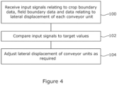
- a method of operation of a mower combination in accordance with the first aspect of the invention comprises the steps of receiving a plurality of signals, the signals representing unprocessed crop boundary data, field boundary data, and data relating to a lateral displacement of each of two conveyor units, comparing the plurality of signals for the unprocessed crop boundary data, the field boundary data and a lateral displacement of one or more of the conveyor units against a predetermined set of target values and adjusting the lateral displacement of at least one conveyor unit based on this comparison.
- a computer readable program comprises instructions which when executed by a computer, causes the mower combination of the first aspect of the invention to implement the method of the second aspect of the invention.
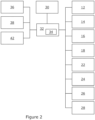
- FIG. 1 a plan view of a mower combination 2 for use in the present invention is shown. (For reasons of clarity, substantially only the wheels of the agricultural vehicle are shown in Figures 3a,3b and 5a,5b ).
- a mower combination 2 comprises an agricultural vehicle 4 such as a tractor and a number of mowing units 6,8,10 suitable for cutting standing crop, the mowing units 6,8,10 being connected to the agricultural vehicle.
- the mowing units include a front mowing unit 6 located to the front of the agricultural vehicle 4 and two lateral mowing units 8,10 located behind and to the sides of the agricultural vehicle 4, each of the mowing units 6,8,10 being adapted to cut crop.
- the front mowing unit 6 is conveniently mounted on a front hitch 12 of the agricultural vehicle 4.
- the two lateral mowing units 8,10 are conveniently mounted on a central chassis supported from a rear hitch 14 of the agricultural vehicle 4.
- the lateral mowing units 8,10 are supported from a central chassis by hydraulic apparatus 22,24.
- Each hydraulic unit 22,24 may be used to move a respective lateral mowing unit 8,10 from a working position to a transport position.
- a headland position may be defined between the working position and the transport position.
- the height of each of the lateral mowing units 8,10 above the ground surface may be further controlled by operation of the hydraulic apparatus 22,24.
- a swath 20 produced by the front mowing unit 6 is shown.
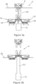
- conveyor units 16,18 mounted to the rear of the lateral mowing units 8,10 are adapted to direct the deposit of cut crop material to one side or the other of the respective lateral mowing units 8,10 to produce a broader central swath 21 or one or more additional swathes as desired (cf Figures 3a , 5a ). For clarity, these swathes are omitted from Figure 1 .
- the conveyor units 16,18 are mounted to be displaceable with respect to the lateral mowing units 8,10.
- the conveyor units may be displaced by hydraulic apparatus 26,28 or other suitable apparatus.
- the conveyor units 16,18 are mounted to be displaced (arrows A in Figures 1 and 3a ) in a direction lateral to a direction of travel (arrow T in Figure 1 ) of the mower combination 2.
- the conveyor units 8,10 can comprise conveyor belts or conveyor screws.
- An operator can control operation of the front and rear mowing units 6,8,10 from within the agricultural vehicle 4 by use of a suitable user terminal 30.
- the operator can control the lateral displacement of the conveyor units, can cause each of the mowing units 6,8,10 to move from a working position to a headland position, can cause the rear mowing units 8,10 to move from the working position to a transport position, or can cause the conveyor units 16,18 to move from an active position to an inactive position.
- the user terminal 30 communicates with an electronic control unit 32.
- the control unit 32 may provide signals to control operation of the front and rear hitches 12,14 of the agricultural vehicle 4 and provides signals to control operation of the mowing units 6,8,10 and the conveyor units 16,18 eg to control the lateral displacement of the conveyor units 16,18.
- the signals are provided by way of a suitable data communication network such as one compliant with the ISOBUS standard (a network in conformance to ISO 11783).
- the control unit 32 may conveniently comprise a single processor located on the agricultural vehicle or its functions may be split between a processor located on the agricultural vehicle and one or more additional processors located on the mowing units 6,8,10, the additional processor(s) being in electronic communication with the first processor.
- the control unit 32 is also able to access a suitable memory 34.
- the memory 34 may take any suitable form and is in electronic communication with the control unit 32.
- the memory 34 is adapted to store, in any suitable manner such as a database or look up table, reference values for a desired lateral displacement of the conveyor units 16,18 in the presence or absence of unprocessed crop ahead of the mower combination.
- the mower combination 2 further comprises a plurality of sensors adapted to provide input signals to be received by the control unit 32.
- An input signal representing the presence of an unprocessed crop boundary is provided.
- the presence or absence of unprocessed crop can be provided by a suitable sensor or sensors 36.
- the sensor is provided on the front mower unit 6 or the agricultural vehicle 4. Any suitable sensor may be utilised, including for example a camera.
- the input signal could be provided as a result of information provided by a GPS sensor, for example the location of the mower combination 2 may be known or calculated from existing mapped data allowing the control unit 32 to determine whether the location to be traversed has previously been processed and accordingly whether crop in front of the mower combination has been or is yet to be processed and accordingly, the relative location of both the unprocessed crop boundary and the field boundary.
- a network interface 42 connected to the control unit 32 is provided.
- the network interface 42 can comprise hardware and/or software that enables wireless connection to one or more remotely located computing devices over a network (e.g., a wireless or mixed wireless and wired network).
- a network e.g., a wireless or mixed wireless and wired network
- the network interface 42 may cooperate with browser software or other software of the control unit 30 to communicate with a server device, enabling remote monitoring or control of the mower combination 2.
- the GPS sensor may also be sued to provide an input signal representative of the location of the field boundary (including the location of the headland).
- the data relating to the field boundary may be downloaded by way of the network interface 42 or otherwise signalled to the control unit 32 before commencing operation of the mower combination.
- Suitable sensors 38 mounted on the mower combination 2, for example on the conveyor units 16,18 can provide input signals representative of the lateral displacement of the conveyor units 16,18.
- the lateral displacement may be measured from any suitable reference point.
- the control unit 32 is configured to receive the input signals representing the presence or absence of unprocessed crop and the lateral displacement of the conveyor units 16,18 and to compare the input signals with the reference values for a reference lateral displacement of the conveyor units 16,18 and, as required, adjust the lateral displacement of at least one conveyor unit 16,18 based on this comparison.
- the control unit 32 receives signals indicating that the unprocessed crop boundary is approaching the field boundary and a current lateral displacement of the conveyor units 16,18 (step 100, Figure 4 ). Based on a comparison of the input signals with the reference target values stored in the memory 34 (step 102), the control unit 32 causes the lateral displacement of each of the conveyor units 16,18 to be adjusted (step 102). The mower combination will then create a swath of narrower width 21' as it traverses the final section of unprocessed crop ahead of the headland region ( Figure 3b ) and the unprocessed crop boundary meets the field boundary. The control unit 32 can then cause the rear mowing units 8,10 (and the associated conveyors 16,18) to adopt a headland position.
- the control unit 32 receives signals indicating the field boundary.
- the control unit 32 lowers the rear mowing units 8,10 from the headland position to a working position to meet the field boundary.
- the control unit 32 then receives signals indicating that the unprocessed crop boundary is moving away from the field boundary.
- the control unit 32 Based on a comparison of the input signals with the reference values stored in the memory 34, after depositing the cut crop as a swath of relatively narrow width on the initial cutting of the unprocessed crop away from the field boundary, the control unit 32 then causes the lateral displacement of each conveyor unit 16,18 to be adjusted outward such a that the cut crop is deposited as a swath of regular width.
- the control unit 32 may also receive signals indicative of the speed of the agricultural vehicle allowing the control unit 32 a further means of determining the relative position of the mower combination from the field boundary and to adjust the lateral displacement of at least one conveyor unit.
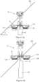
- FIGS 5a and 5b illustrate a common situation, namely that of an angled headland or field boundary 60.
- the control unit 30 based upon the input signals will determine that the unprocessed crop interface varies to the left and to the right of the mower combination.
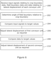
- the control unit 32 receives signals indicating that the unprocessed crop boundary is approaching the field boundary and a current lateral displacement of the conveyor units 16,18 (step 200, Figure 6 ).
- the control unit 32 is able to determine an angle ⁇ (in Figures 5a and 5b running from left to right) between the field boundary 60 and the crop boundary (step 202, Figure 6 ).
- the control unit 32 Based on a continuous comparison of the input signals (and so the angle ⁇ ) with the reference values stored in the memory 34 (steps 204,208), the control unit 32 causes the lateral displacement of a first conveyor unit 16 to be adjusted (step 206, Figure 6 ) - in Figure 5a the left hand conveyor unit (arrow C) - and then subsequently the lateral displacement of a second conveyor unit 18 (step 220 Figure 6 ) in Figure 5b the right hand conveyor unit (arrow D).
- control unit 30 determines on the basis of signals from the sensors 36 a first crop boundary location ahead of a first lateral mower unit and its associated conveyor unit and a second crop boundary location ahead of the second lateral mower unit and its associated conveyor unit. Based upon the comparison of the input signals with the reference values stored in the memory 34, the control unit 32 causes the lateral displacement of each of the conveyor units in turn.
- control unit 32 may receive input from the user terminal 30, as entered by the operator. For instance, the operator may prompt a display of the parameters (the distance to or from an unprocessed crop interface to a field boundary, the lateral displacement of the conveyor units 16,18).
- the control unit 32 provides the corresponding information for rendering on a display screen in the agricultural vehicle 4. Additionally or alternatively the control unit 32 may provides the corresponding information for rendering on a display screen remote from the agricultural vehicle 4.
- the operator may use the user terminal 32 to configure the width of a tapered swath and or the length of the swath of reduced width as desired.
- control unit 32 may provide feedback of the automatic adjustment in the lateral position of the conveyor units 16,18 to the operator via the user terminal 30, for example visually or audibly.
Landscapes
- Life Sciences & Earth Sciences (AREA)
- Environmental Sciences (AREA)
- Harvester Elements (AREA)
Priority Applications (1)
| Application Number | Priority Date | Filing Date | Title |
|---|---|---|---|
| SI202030259T SI3837954T1 (sl) | 2019-12-19 | 2020-12-17 | Kombinacija kosilnic |
Applications Claiming Priority (1)
| Application Number | Priority Date | Filing Date | Title |
|---|---|---|---|
| GBGB1918845.7A GB201918845D0 (en) | 2019-12-19 | 2019-12-19 | Mower combination |
Publications (2)
| Publication Number | Publication Date |
|---|---|
| EP3837954A1 EP3837954A1 (en) | 2021-06-23 |
| EP3837954B1 true EP3837954B1 (en) | 2023-08-23 |
Family
ID=69322843
Family Applications (1)
| Application Number | Title | Priority Date | Filing Date |
|---|---|---|---|
| EP20214897.9A Active EP3837954B1 (en) | 2019-12-19 | 2020-12-17 | Mower combination |
Country Status (6)
| Country | Link |
|---|---|
| US (1) | US20210185928A1 (da) |
| EP (1) | EP3837954B1 (da) |
| DK (1) | DK3837954T3 (da) |
| GB (1) | GB201918845D0 (da) |
| PL (1) | PL3837954T3 (da) |
| SI (1) | SI3837954T1 (da) |
Families Citing this family (1)
| Publication number | Priority date | Publication date | Assignee | Title |
|---|---|---|---|---|
| FR3160083A1 (fr) * | 2024-03-14 | 2025-09-19 | Kuhn Sas | Procédé de fonctionnement pour une machine de récolte à plusieurs unités, et machine de récolte associée |
Family Cites Families (6)
| Publication number | Priority date | Publication date | Assignee | Title |
|---|---|---|---|---|
| FR2837347B1 (fr) * | 2002-03-21 | 2004-07-30 | Kuhn Sa | Faucheuse agricole comportant un vehicule porteur et plusieurs unites de travail |
| NL1037815C2 (nl) * | 2010-03-18 | 2011-09-20 | Forage Innovations Bv | Hooibouwinrichting. |
| DE202011101277U1 (de) * | 2011-05-31 | 2011-09-26 | Fella-Werke Gmbh | Mähwerkskombination |
| EP3251484B1 (de) * | 2016-06-03 | 2018-09-26 | Kverneland Group Kerteminde A/S | Verfahren und vorrichtung zum betreiben einer landwirtschaftlichen maschine |
| DE102017216196A1 (de) * | 2017-09-13 | 2019-03-14 | Deere & Company | Verfahren zur Querverschiebung eines Mähwerks eines landwirtschaftlichen Fahrzeugs |
| US11363753B2 (en) * | 2019-10-24 | 2022-06-21 | Deere & Company | Mower implement guidance system |
-
2019
- 2019-12-19 GB GBGB1918845.7A patent/GB201918845D0/en not_active Ceased
-
2020
- 2020-12-17 SI SI202030259T patent/SI3837954T1/sl unknown
- 2020-12-17 DK DK20214897.9T patent/DK3837954T3/da active
- 2020-12-17 PL PL20214897.9T patent/PL3837954T3/pl unknown
- 2020-12-17 EP EP20214897.9A patent/EP3837954B1/en active Active
- 2020-12-19 US US17/128,060 patent/US20210185928A1/en not_active Abandoned
Also Published As
| Publication number | Publication date |
|---|---|
| SI3837954T1 (sl) | 2023-10-30 |
| DK3837954T3 (da) | 2023-11-13 |
| EP3837954A1 (en) | 2021-06-23 |
| PL3837954T3 (pl) | 2024-02-19 |
| GB201918845D0 (en) | 2020-02-05 |
| US20210185928A1 (en) | 2021-06-24 |
Similar Documents
| Publication | Publication Date | Title |
|---|---|---|
| EP2893797B1 (de) | Erntevorrichtung | |
| EP2803256B1 (de) | Erntemaschine mit vorausschauender Vortriebsgeschwindigkeitsregelung | |
| EP2452551B1 (de) | Steueranordnung zur Kontrolle des Überladens landwirtschaftlichen Ernteguts von einer Erntemaschine auf ein Transportfahrzeug | |
| US12248322B2 (en) | Agricultural machine | |
| EP3878262A1 (en) | Agricultural apparatus | |
| EP3878267B1 (en) | Mower combination | |
| EP4212003A1 (en) | Agricultural residue depositing apparatus and method | |
| US10959378B2 (en) | Unloading system for agricultural harvesting machines | |
| US20230345879A1 (en) | Working machine and working device | |
| EP1685759B2 (de) | Vorrichtung zur gleichmässigen Beschickung von Arbeitsmaschinen | |
| EP3837954B1 (en) | Mower combination | |
| EP3837952B1 (en) | Mower combination | |
| WO2019179756A1 (de) | Verfahren zum ermitteln einer bestandhöhe von feldpflanzen | |
| US11778949B2 (en) | Mower combination with location based conveyor control | |
| US11950532B2 (en) | Mower combination with location based conveyor control | |
| EP3878264B1 (en) | Agricultural apparatus | |
| EP3837953B1 (en) | Agricultural apparatus | |
| EP4014709A1 (en) | Agricultural apparatus with cutting height control | |
| JP7203717B2 (ja) | 農業機械 | |
| EP3878263B1 (en) | Mower combination | |
| EP3902385A1 (en) | Device for the engagement and disengagement of a power take-off in a vehicle with a trailer operatively joined thereto with a cardan |
Legal Events
| Date | Code | Title | Description |
|---|---|---|---|
| PUAI | Public reference made under article 153(3) epc to a published international application that has entered the european phase |
Free format text: ORIGINAL CODE: 0009012 |
|
| STAA | Information on the status of an ep patent application or granted ep patent |
Free format text: STATUS: THE APPLICATION HAS BEEN PUBLISHED |
|
| AK | Designated contracting states |
Kind code of ref document: A1 Designated state(s): AL AT BE BG CH CY CZ DE DK EE ES FI FR GB GR HR HU IE IS IT LI LT LU LV MC MK MT NL NO PL PT RO RS SE SI SK SM TR |
|
| STAA | Information on the status of an ep patent application or granted ep patent |
Free format text: STATUS: REQUEST FOR EXAMINATION WAS MADE |
|
| 17P | Request for examination filed |
Effective date: 20211223 |
|
| RBV | Designated contracting states (corrected) |
Designated state(s): AL AT BE BG CH CY CZ DE DK EE ES FI FR GB GR HR HU IE IS IT LI LT LU LV MC MK MT NL NO PL PT RO RS SE SI SK SM TR |
|
| GRAP | Despatch of communication of intention to grant a patent |
Free format text: ORIGINAL CODE: EPIDOSNIGR1 |
|
| STAA | Information on the status of an ep patent application or granted ep patent |
Free format text: STATUS: GRANT OF PATENT IS INTENDED |
|
| RIC1 | Information provided on ipc code assigned before grant |
Ipc: A01D 75/30 20060101ALI20230504BHEP Ipc: A01D 57/20 20060101ALI20230504BHEP Ipc: A01D 34/66 20060101AFI20230504BHEP |
|
| P01 | Opt-out of the competence of the unified patent court (upc) registered |
Effective date: 20230518 |
|
| INTG | Intention to grant announced |
Effective date: 20230531 |
|
| GRAS | Grant fee paid |
Free format text: ORIGINAL CODE: EPIDOSNIGR3 |
|
| GRAA | (expected) grant |
Free format text: ORIGINAL CODE: 0009210 |
|
| STAA | Information on the status of an ep patent application or granted ep patent |
Free format text: STATUS: THE PATENT HAS BEEN GRANTED |
|
| AK | Designated contracting states |
Kind code of ref document: B1 Designated state(s): AL AT BE BG CH CY CZ DE DK EE ES FI FR GB GR HR HU IE IS IT LI LT LU LV MC MK MT NL NO PL PT RO RS SE SI SK SM TR |
|
| REG | Reference to a national code |
Ref country code: GB Ref legal event code: FG4D |
|
| REG | Reference to a national code |
Ref country code: CH Ref legal event code: EP |
|
| REG | Reference to a national code |
Ref country code: DE Ref legal event code: R096 Ref document number: 602020016184 Country of ref document: DE |
|
| REG | Reference to a national code |
Ref country code: IE Ref legal event code: FG4D |
|
| REG | Reference to a national code |
Ref country code: DK Ref legal event code: T3 Effective date: 20231108 |
|
| REG | Reference to a national code |
Ref country code: LT Ref legal event code: MG9D |
|
| REG | Reference to a national code |
Ref country code: NL Ref legal event code: MP Effective date: 20230823 |
|
| PG25 | Lapsed in a contracting state [announced via postgrant information from national office to epo] |
Ref country code: GR Free format text: LAPSE BECAUSE OF FAILURE TO SUBMIT A TRANSLATION OF THE DESCRIPTION OR TO PAY THE FEE WITHIN THE PRESCRIBED TIME-LIMIT Effective date: 20231124 |
|
| PG25 | Lapsed in a contracting state [announced via postgrant information from national office to epo] |
Ref country code: IS Free format text: LAPSE BECAUSE OF FAILURE TO SUBMIT A TRANSLATION OF THE DESCRIPTION OR TO PAY THE FEE WITHIN THE PRESCRIBED TIME-LIMIT Effective date: 20231223 |
|
| PG25 | Lapsed in a contracting state [announced via postgrant information from national office to epo] |
Ref country code: SE Free format text: LAPSE BECAUSE OF FAILURE TO SUBMIT A TRANSLATION OF THE DESCRIPTION OR TO PAY THE FEE WITHIN THE PRESCRIBED TIME-LIMIT Effective date: 20230823 Ref country code: RS Free format text: LAPSE BECAUSE OF FAILURE TO SUBMIT A TRANSLATION OF THE DESCRIPTION OR TO PAY THE FEE WITHIN THE PRESCRIBED TIME-LIMIT Effective date: 20230823 Ref country code: PT Free format text: LAPSE BECAUSE OF FAILURE TO SUBMIT A TRANSLATION OF THE DESCRIPTION OR TO PAY THE FEE WITHIN THE PRESCRIBED TIME-LIMIT Effective date: 20231226 Ref country code: NO Free format text: LAPSE BECAUSE OF FAILURE TO SUBMIT A TRANSLATION OF THE DESCRIPTION OR TO PAY THE FEE WITHIN THE PRESCRIBED TIME-LIMIT Effective date: 20231123 Ref country code: NL Free format text: LAPSE BECAUSE OF FAILURE TO SUBMIT A TRANSLATION OF THE DESCRIPTION OR TO PAY THE FEE WITHIN THE PRESCRIBED TIME-LIMIT Effective date: 20230823 Ref country code: LV Free format text: LAPSE BECAUSE OF FAILURE TO SUBMIT A TRANSLATION OF THE DESCRIPTION OR TO PAY THE FEE WITHIN THE PRESCRIBED TIME-LIMIT Effective date: 20230823 Ref country code: LT Free format text: LAPSE BECAUSE OF FAILURE TO SUBMIT A TRANSLATION OF THE DESCRIPTION OR TO PAY THE FEE WITHIN THE PRESCRIBED TIME-LIMIT Effective date: 20230823 Ref country code: IS Free format text: LAPSE BECAUSE OF FAILURE TO SUBMIT A TRANSLATION OF THE DESCRIPTION OR TO PAY THE FEE WITHIN THE PRESCRIBED TIME-LIMIT Effective date: 20231223 Ref country code: HR Free format text: LAPSE BECAUSE OF FAILURE TO SUBMIT A TRANSLATION OF THE DESCRIPTION OR TO PAY THE FEE WITHIN THE PRESCRIBED TIME-LIMIT Effective date: 20230823 Ref country code: GR Free format text: LAPSE BECAUSE OF FAILURE TO SUBMIT A TRANSLATION OF THE DESCRIPTION OR TO PAY THE FEE WITHIN THE PRESCRIBED TIME-LIMIT Effective date: 20231124 Ref country code: FI Free format text: LAPSE BECAUSE OF FAILURE TO SUBMIT A TRANSLATION OF THE DESCRIPTION OR TO PAY THE FEE WITHIN THE PRESCRIBED TIME-LIMIT Effective date: 20230823 |
|
| REG | Reference to a national code |
Ref country code: AT Ref legal event code: UEP Ref document number: 1601422 Country of ref document: AT Kind code of ref document: T Effective date: 20230823 |
|
| PG25 | Lapsed in a contracting state [announced via postgrant information from national office to epo] |
Ref country code: ES Free format text: LAPSE BECAUSE OF FAILURE TO SUBMIT A TRANSLATION OF THE DESCRIPTION OR TO PAY THE FEE WITHIN THE PRESCRIBED TIME-LIMIT Effective date: 20230823 |
|
| PG25 | Lapsed in a contracting state [announced via postgrant information from national office to epo] |
Ref country code: SM Free format text: LAPSE BECAUSE OF FAILURE TO SUBMIT A TRANSLATION OF THE DESCRIPTION OR TO PAY THE FEE WITHIN THE PRESCRIBED TIME-LIMIT Effective date: 20230823 Ref country code: RO Free format text: LAPSE BECAUSE OF FAILURE TO SUBMIT A TRANSLATION OF THE DESCRIPTION OR TO PAY THE FEE WITHIN THE PRESCRIBED TIME-LIMIT Effective date: 20230823 Ref country code: ES Free format text: LAPSE BECAUSE OF FAILURE TO SUBMIT A TRANSLATION OF THE DESCRIPTION OR TO PAY THE FEE WITHIN THE PRESCRIBED TIME-LIMIT Effective date: 20230823 Ref country code: EE Free format text: LAPSE BECAUSE OF FAILURE TO SUBMIT A TRANSLATION OF THE DESCRIPTION OR TO PAY THE FEE WITHIN THE PRESCRIBED TIME-LIMIT Effective date: 20230823 Ref country code: CZ Free format text: LAPSE BECAUSE OF FAILURE TO SUBMIT A TRANSLATION OF THE DESCRIPTION OR TO PAY THE FEE WITHIN THE PRESCRIBED TIME-LIMIT Effective date: 20230823 Ref country code: SK Free format text: LAPSE BECAUSE OF FAILURE TO SUBMIT A TRANSLATION OF THE DESCRIPTION OR TO PAY THE FEE WITHIN THE PRESCRIBED TIME-LIMIT Effective date: 20230823 |
|
| REG | Reference to a national code |
Ref country code: DE Ref legal event code: R097 Ref document number: 602020016184 Country of ref document: DE |
|
| PLBE | No opposition filed within time limit |
Free format text: ORIGINAL CODE: 0009261 |
|
| STAA | Information on the status of an ep patent application or granted ep patent |
Free format text: STATUS: NO OPPOSITION FILED WITHIN TIME LIMIT |
|
| 26N | No opposition filed |
Effective date: 20240524 |
|
| REG | Reference to a national code |
Ref country code: CH Ref legal event code: PL |
|
| PG25 | Lapsed in a contracting state [announced via postgrant information from national office to epo] |
Ref country code: LU Free format text: LAPSE BECAUSE OF NON-PAYMENT OF DUE FEES Effective date: 20231217 |
|
| PG25 | Lapsed in a contracting state [announced via postgrant information from national office to epo] |
Ref country code: MC Free format text: LAPSE BECAUSE OF FAILURE TO SUBMIT A TRANSLATION OF THE DESCRIPTION OR TO PAY THE FEE WITHIN THE PRESCRIBED TIME-LIMIT Effective date: 20230823 |
|
| PG25 | Lapsed in a contracting state [announced via postgrant information from national office to epo] |
Ref country code: MC Free format text: LAPSE BECAUSE OF FAILURE TO SUBMIT A TRANSLATION OF THE DESCRIPTION OR TO PAY THE FEE WITHIN THE PRESCRIBED TIME-LIMIT Effective date: 20230823 Ref country code: LU Free format text: LAPSE BECAUSE OF NON-PAYMENT OF DUE FEES Effective date: 20231217 |
|
| PG25 | Lapsed in a contracting state [announced via postgrant information from national office to epo] |
Ref country code: CH Free format text: LAPSE BECAUSE OF NON-PAYMENT OF DUE FEES Effective date: 20231231 |
|
| PG25 | Lapsed in a contracting state [announced via postgrant information from national office to epo] |
Ref country code: CH Free format text: LAPSE BECAUSE OF NON-PAYMENT OF DUE FEES Effective date: 20231231 |
|
| PG25 | Lapsed in a contracting state [announced via postgrant information from national office to epo] |
Ref country code: BG Free format text: LAPSE BECAUSE OF FAILURE TO SUBMIT A TRANSLATION OF THE DESCRIPTION OR TO PAY THE FEE WITHIN THE PRESCRIBED TIME-LIMIT Effective date: 20230823 |
|
| PG25 | Lapsed in a contracting state [announced via postgrant information from national office to epo] |
Ref country code: BG Free format text: LAPSE BECAUSE OF FAILURE TO SUBMIT A TRANSLATION OF THE DESCRIPTION OR TO PAY THE FEE WITHIN THE PRESCRIBED TIME-LIMIT Effective date: 20230823 |
|
| PG25 | Lapsed in a contracting state [announced via postgrant information from national office to epo] |
Ref country code: CY Free format text: LAPSE BECAUSE OF FAILURE TO SUBMIT A TRANSLATION OF THE DESCRIPTION OR TO PAY THE FEE WITHIN THE PRESCRIBED TIME-LIMIT; INVALID AB INITIO Effective date: 20201217 |
|
| PG25 | Lapsed in a contracting state [announced via postgrant information from national office to epo] |
Ref country code: HU Free format text: LAPSE BECAUSE OF FAILURE TO SUBMIT A TRANSLATION OF THE DESCRIPTION OR TO PAY THE FEE WITHIN THE PRESCRIBED TIME-LIMIT; INVALID AB INITIO Effective date: 20201217 |
|
| GBPC | Gb: european patent ceased through non-payment of renewal fee |
Effective date: 20241217 |
|
| PG25 | Lapsed in a contracting state [announced via postgrant information from national office to epo] |
Ref country code: GB Free format text: LAPSE BECAUSE OF NON-PAYMENT OF DUE FEES Effective date: 20241217 |
|
| PG25 | Lapsed in a contracting state [announced via postgrant information from national office to epo] |
Ref country code: TR Free format text: LAPSE BECAUSE OF FAILURE TO SUBMIT A TRANSLATION OF THE DESCRIPTION OR TO PAY THE FEE WITHIN THE PRESCRIBED TIME-LIMIT Effective date: 20230823 |
|
| PGFP | Annual fee paid to national office [announced via postgrant information from national office to epo] |
Ref country code: DE Payment date: 20251211 Year of fee payment: 6 |
|
| PGFP | Annual fee paid to national office [announced via postgrant information from national office to epo] |
Ref country code: AT Payment date: 20251222 Year of fee payment: 6 |
|
| PGFP | Annual fee paid to national office [announced via postgrant information from national office to epo] |
Ref country code: IT Payment date: 20251222 Year of fee payment: 6 Ref country code: DK Payment date: 20251224 Year of fee payment: 6 |
|
| PGFP | Annual fee paid to national office [announced via postgrant information from national office to epo] |
Ref country code: FR Payment date: 20251229 Year of fee payment: 6 |
|
| PGFP | Annual fee paid to national office [announced via postgrant information from national office to epo] |
Ref country code: BE Payment date: 20251219 Year of fee payment: 6 |
|
| PGFP | Annual fee paid to national office [announced via postgrant information from national office to epo] |
Ref country code: IE Payment date: 20251219 Year of fee payment: 6 |
|
| PGFP | Annual fee paid to national office [announced via postgrant information from national office to epo] |
Ref country code: PL Payment date: 20251204 Year of fee payment: 6 |
|
| PGFP | Annual fee paid to national office [announced via postgrant information from national office to epo] |
Ref country code: SI Payment date: 20251204 Year of fee payment: 6 |