EP3838245A1 - Module de base, système médical et procédé de fonctionnement du système médical - Google Patents
Module de base, système médical et procédé de fonctionnement du système médical Download PDFInfo
- Publication number
- EP3838245A1 EP3838245A1 EP19216765.8A EP19216765A EP3838245A1 EP 3838245 A1 EP3838245 A1 EP 3838245A1 EP 19216765 A EP19216765 A EP 19216765A EP 3838245 A1 EP3838245 A1 EP 3838245A1
- Authority
- EP
- European Patent Office
- Prior art keywords
- medical system
- module
- base module
- designed
- medical
- Prior art date
- Legal status (The legal status is an assumption and is not a legal conclusion. Google has not performed a legal analysis and makes no representation as to the accuracy of the status listed.)
- Ceased
Links
Images

Classifications
-
- A—HUMAN NECESSITIES
- A61—MEDICAL OR VETERINARY SCIENCE; HYGIENE
- A61B—DIAGNOSIS; SURGERY; IDENTIFICATION
- A61B6/00—Apparatus or devices for radiation diagnosis; Apparatus or devices for radiation diagnosis combined with radiation therapy equipment
-
- A—HUMAN NECESSITIES
- A61—MEDICAL OR VETERINARY SCIENCE; HYGIENE
- A61G—TRANSPORT, PERSONAL CONVEYANCES, OR ACCOMMODATION SPECIALLY ADAPTED FOR PATIENTS OR DISABLED PERSONS; OPERATING TABLES OR CHAIRS; CHAIRS FOR DENTISTRY; FUNERAL DEVICES
- A61G7/00—Beds specially adapted for nursing; Devices for lifting patients or disabled persons
- A61G7/08—Apparatus for transporting beds
-
- A—HUMAN NECESSITIES
- A61—MEDICAL OR VETERINARY SCIENCE; HYGIENE
- A61B—DIAGNOSIS; SURGERY; IDENTIFICATION
- A61B6/00—Apparatus or devices for radiation diagnosis; Apparatus or devices for radiation diagnosis combined with radiation therapy equipment
- A61B6/02—Arrangements for diagnosis sequentially in different planes; Stereoscopic radiation diagnosis
- A61B6/03—Computed tomography [CT]
- A61B6/032—Transmission computed tomography [CT]
- A61B6/035—Mechanical aspects of CT
-
- A—HUMAN NECESSITIES
- A61—MEDICAL OR VETERINARY SCIENCE; HYGIENE
- A61B—DIAGNOSIS; SURGERY; IDENTIFICATION
- A61B6/00—Apparatus or devices for radiation diagnosis; Apparatus or devices for radiation diagnosis combined with radiation therapy equipment
- A61B6/04—Positioning of patients; Tiltable beds or the like
- A61B6/0407—Supports, e.g. tables or beds, for the body or parts of the body
-
- A—HUMAN NECESSITIES
- A61—MEDICAL OR VETERINARY SCIENCE; HYGIENE
- A61B—DIAGNOSIS; SURGERY; IDENTIFICATION
- A61B6/00—Apparatus or devices for radiation diagnosis; Apparatus or devices for radiation diagnosis combined with radiation therapy equipment
- A61B6/44—Constructional features of apparatus for radiation diagnosis
- A61B6/4405—Constructional features of apparatus for radiation diagnosis the apparatus being movable or portable, e.g. handheld or mounted on a trolley
-
- A—HUMAN NECESSITIES
- A61—MEDICAL OR VETERINARY SCIENCE; HYGIENE
- A61B—DIAGNOSIS; SURGERY; IDENTIFICATION
- A61B8/00—Diagnosis using ultrasonic, sonic or infrasonic waves
- A61B8/40—Positioning of patients, e.g. means for holding or immobilising parts of the patient's body
-
- A—HUMAN NECESSITIES
- A61—MEDICAL OR VETERINARY SCIENCE; HYGIENE
- A61G—TRANSPORT, PERSONAL CONVEYANCES, OR ACCOMMODATION SPECIALLY ADAPTED FOR PATIENTS OR DISABLED PERSONS; OPERATING TABLES OR CHAIRS; CHAIRS FOR DENTISTRY; FUNERAL DEVICES
- A61G13/00—Operating tables; Auxiliary appliances therefor
- A61G13/10—Parts, details or accessories
- A61G13/104—Adaptations for table mobility, e.g. arrangement of wheels
-
- B—PERFORMING OPERATIONS; TRANSPORTING
- B60—VEHICLES IN GENERAL
- B60B—VEHICLE WHEELS; CASTORS; AXLES FOR WHEELS OR CASTORS; INCREASING WHEEL ADHESION
- B60B33/00—Castors in general ; Anti-clogging castors
- B60B33/0036—Castors in general ; Anti-clogging castors characterised by type of wheels
- B60B33/0044—Roller type wheels, i.e. extra wide wheels
-
- B—PERFORMING OPERATIONS; TRANSPORTING
- B60—VEHICLES IN GENERAL
- B60B—VEHICLE WHEELS; CASTORS; AXLES FOR WHEELS OR CASTORS; INCREASING WHEEL ADHESION
- B60B33/00—Castors in general ; Anti-clogging castors
- B60B33/04—Castors in general ; Anti-clogging castors adjustable, e.g. in height; linearly shifting castors
- B60B33/06—Castors in general ; Anti-clogging castors adjustable, e.g. in height; linearly shifting castors mounted retractably
-
- G—PHYSICS
- G01—MEASURING; TESTING
- G01D—MEASURING NOT SPECIALLY ADAPTED FOR A SPECIFIC VARIABLE; ARRANGEMENTS FOR MEASURING TWO OR MORE VARIABLES NOT COVERED IN A SINGLE OTHER SUBCLASS; TARIFF METERING APPARATUS; MEASURING OR TESTING NOT OTHERWISE PROVIDED FOR
- G01D21/00—Measuring or testing not otherwise provided for
- G01D21/02—Measuring two or more variables by means not covered by a single other subclass
-
- G—PHYSICS
- G16—INFORMATION AND COMMUNICATION TECHNOLOGY [ICT] SPECIALLY ADAPTED FOR SPECIFIC APPLICATION FIELDS
- G16H—HEALTHCARE INFORMATICS, i.e. INFORMATION AND COMMUNICATION TECHNOLOGY [ICT] SPECIALLY ADAPTED FOR THE HANDLING OR PROCESSING OF MEDICAL OR HEALTHCARE DATA
- G16H40/00—ICT specially adapted for the management or administration of healthcare resources or facilities; ICT specially adapted for the management or operation of medical equipment or devices
- G16H40/60—ICT specially adapted for the management or administration of healthcare resources or facilities; ICT specially adapted for the management or operation of medical equipment or devices for the operation of medical equipment or devices
- G16H40/67—ICT specially adapted for the management or administration of healthcare resources or facilities; ICT specially adapted for the management or operation of medical equipment or devices for the operation of medical equipment or devices for remote operation
-
- H—ELECTRICITY
- H04—ELECTRIC COMMUNICATION TECHNIQUE
- H04L—TRANSMISSION OF DIGITAL INFORMATION, e.g. TELEGRAPHIC COMMUNICATION
- H04L12/00—Data switching networks
- H04L12/28—Data switching networks characterised by path configuration, e.g. LAN [Local Area Networks] or WAN [Wide Area Networks]
- H04L12/40—Bus networks
-
- H—ELECTRICITY
- H04—ELECTRIC COMMUNICATION TECHNIQUE
- H04L—TRANSMISSION OF DIGITAL INFORMATION, e.g. TELEGRAPHIC COMMUNICATION
- H04L67/00—Network arrangements or protocols for supporting network services or applications
- H04L67/01—Protocols
- H04L67/12—Protocols specially adapted for proprietary or special-purpose networking environments, e.g. medical networks, sensor networks, networks in vehicles or remote metering networks
-
- A—HUMAN NECESSITIES
- A61—MEDICAL OR VETERINARY SCIENCE; HYGIENE
- A61B—DIAGNOSIS; SURGERY; IDENTIFICATION
- A61B6/00—Apparatus or devices for radiation diagnosis; Apparatus or devices for radiation diagnosis combined with radiation therapy equipment
- A61B6/02—Arrangements for diagnosis sequentially in different planes; Stereoscopic radiation diagnosis
- A61B6/03—Computed tomography [CT]
- A61B6/032—Transmission computed tomography [CT]
-
- A—HUMAN NECESSITIES
- A61—MEDICAL OR VETERINARY SCIENCE; HYGIENE
- A61G—TRANSPORT, PERSONAL CONVEYANCES, OR ACCOMMODATION SPECIALLY ADAPTED FOR PATIENTS OR DISABLED PERSONS; OPERATING TABLES OR CHAIRS; CHAIRS FOR DENTISTRY; FUNERAL DEVICES
- A61G2203/00—General characteristics of devices
- A61G2203/10—General characteristics of devices characterised by specific control means, e.g. for adjustment or steering
- A61G2203/18—General characteristics of devices characterised by specific control means, e.g. for adjustment or steering by patient's head, eyes, facial muscles or voice
-
- A—HUMAN NECESSITIES
- A61—MEDICAL OR VETERINARY SCIENCE; HYGIENE
- A61G—TRANSPORT, PERSONAL CONVEYANCES, OR ACCOMMODATION SPECIALLY ADAPTED FOR PATIENTS OR DISABLED PERSONS; OPERATING TABLES OR CHAIRS; CHAIRS FOR DENTISTRY; FUNERAL DEVICES
- A61G2203/00—General characteristics of devices
- A61G2203/30—General characteristics of devices characterised by sensor means
-
- A—HUMAN NECESSITIES
- A61—MEDICAL OR VETERINARY SCIENCE; HYGIENE
- A61G—TRANSPORT, PERSONAL CONVEYANCES, OR ACCOMMODATION SPECIALLY ADAPTED FOR PATIENTS OR DISABLED PERSONS; OPERATING TABLES OR CHAIRS; CHAIRS FOR DENTISTRY; FUNERAL DEVICES
- A61G2210/00—Devices for specific treatment or diagnosis
- A61G2210/50—Devices for specific treatment or diagnosis for radiography
-
- H—ELECTRICITY
- H04—ELECTRIC COMMUNICATION TECHNIQUE
- H04L—TRANSMISSION OF DIGITAL INFORMATION, e.g. TELEGRAPHIC COMMUNICATION
- H04L12/00—Data switching networks
- H04L12/28—Data switching networks characterised by path configuration, e.g. LAN [Local Area Networks] or WAN [Wide Area Networks]
- H04L12/40—Bus networks
- H04L2012/40208—Bus networks characterized by the use of a particular bus standard
- H04L2012/40215—Controller Area Network CAN
Definitions
- the present invention relates to a basic module for a mobile medical system which is designed for autonomous and / or semi-autonomous locomotion.
- the present invention also relates to the medical system designed for the autonomous or semi-autonomous covering of distances and a method for operating such a mobile medical system.
- the medical system represents a platform of a general type that serves in particular as a basis for transporting imaging devices, medical alignment and / or loads, in particular in a clinical environment.
- the megatrend of electrification, automation and digitization is not only finding its way into industry (keyword: Industry 4.0), but is also reflected in the further development of medical processes, clinical procedures and medical devices, especially imaging facilities. This development is generally referred to by the keywords Digital Hospital or Hospital 2.0.
- mobile medical systems for example mobile imaging systems
- mobile imaging systems which are designed to cover paths or distances, for example within a hospital, autonomously or partially autonomously.
- mobile medical systems for example mobile imaging systems
- an autonomously or partially autonomously movable or displaceable imaging system is known.
- DE 10 2011 083 876 B4 discloses, for example, a stationary imaging system that includes a highly mobile x-ray system.
- DE 10 2014 115 901 A1 describes a floor platform for operating tables which comprises an interface for fastening a patient support unit for supporting a patient and an omnidirectional, electric drive unit.
- the drive unit is designed in such a way that the floor platform can be moved and rotated in any direction within a predetermined plane solely by the drive unit.
- an operating unit for controlling the drive unit is provided, this comprising a manual actuating element.
- the operating unit also has a control unit which, as a function of the actuation of the actuating element, determines control signals for the drive unit and transmits them to the drive unit.
- the drive unit moves the floor platform on the basis of the control signals.
- the drive unit of the medical system described comprises several independently controllable driven wheels, the control unit controlling the direction of movement of the floor platform through the individual control of the driven wheels.
- the medical system of DE 10 2014 115 901 A1 is very complex and expensive to implement, as it has eight complex Mecanum wheels.
- a Mecanum wheel is an all-side wheel (also: omnidirectional wheel) in which the running surface of the main wheel is formed by rollers, the axes of which are arranged at an angle with respect to the tangential direction of the main wheel. Since several Mecanum wheels are installed, the medical system is prone to failure and an increased need for maintenance can usually be assumed. In addition, the medical system cannot be used universally, but is only designed to attach a patient support unit.
- a mobile medical system which has two different drive mechanisms.
- a so-called precision drive fine movement mechanism
- coarse drive fine movement mechanism
- coarse drive gross movement mechanism
- belt drive is proposed as an alternative type of drive to the multiple driven wheels.
- the use of two differently designed drive systems in a mobile medical system is complex, expensive and, as a rule, prone to failure and thus entails an increased need for maintenance.
- the proposed medical system cannot be used universally, but is only provided for a mobile imaging device.
- this object is achieved by a base module with the features of claim 1, by a medical system with the features of claim 11 and a method for operating the medical system with the features of claim 15.
- a basic module for a mobile medical system which is designed to cover distances autonomously or semi-autonomously, comprises a chassis having a plurality of rolling bodies.
- the rolling bodies are rotatably mounted about axes of rotation and adjustable in the vertical direction by means of adjusting devices such that each rolling body is between a first position in which the respective rolling body is in contact with a floor surface and a second position in which the respective rolling body is spaced from the floor surface is movable.
- the present invention provides an alternative, comparatively simply structured and modularly designed construction kit solution for an autonomously or partially autonomously (also: semi-autonomously) movable or displaceable medical system.
- the above-mentioned basic module is used for locomotion of the modular medical system. Due to the adjustability of the rolling bodies in the vertical direction, various driving maneuvers, in particular in a confined space, can be carried out in a simple manner. Rolling bodies that would hinder or impair the performance of the respective driving maneuver are automatically drawn in accordingly so that they no longer have any contact with the ground surface. In this way, mechanically complex components, such as omnidirectional wheels or Mecanum wheels, can be dispensed with.
- the medical system according to the invention can be used, for example, as a mobile platform for imaging devices, such as C-arm x-ray devices, computer tomographs, ultrasound devices, and / or for medical equipment, patient beds or the like.
- the medical system can represent a cost-efficient variant of a mobile platform for medical containers or the like, which can be equipped in a modular and demand-oriented manner, i.e. depending on the current use.
- the medical system can therefore be used in many ways.
- the medical system is primarily intended for use in a clinical environment (hospital, medical center, practice, etc.) and can be used for a wide variety of applications in terms of the modular construction principle, for example for imaging devices such as C-arms, computer tomographs or ultrasound devices, and / or for medical equipment, patient beds or the like.
- the medical system is used, for example, as a mobile trolley.
- the medical system represents a movable or movable platform, or a platform that can be shifted with regard to its location, in order to autonomously handle arrangements with a larger mass (in particular imaging modalities, but also other types of heavy mobile clinical tables, cabinets or storage containers) or to move at least partially autonomously between at least two locations.
- At least two axes of rotation of the rolling bodies are arranged in relation to one another in an arrangement which deviates from a parallel or anti-parallel arrangement.
- the chassis of the base module has rolling bodies with at least two different axes of rotation which are oriented to one another at an angle that is different from zero.
- At least two axes of rotation of the rolling bodies are arranged at an obtuse, in particular right, angle to one another.
- the chassis of the base module has, in particular, differently oriented rolling bodies which are used, for example, to move the medical system forwards or backwards and to move the medical system sideways.
- the axes of rotation of the rolling bodies of the chassis form at least one circumferential, in particular rectangular or square, arrangement. Such arrangements are mechanically very stable.
- the rolling bodies are each mounted in pairs so that they can rotate about the axes of rotation.
- at least two rolling bodies are arranged concentrically around each axis of rotation in order to improve the stability of the chassis. In this way, sufficient stability is also ensured if, for example, a rolling element has to be drawn in to carry out a certain driving maneuver and thus no longer has any contact with the ground surface.
- the adjustment device is designed as an adjustable shock absorber, in particular a gas pressure shock absorber.
- the rolling bodies are designed to be essentially cylindrical.
- the rolling bodies have, for example, an essentially constant diameter.
- the rolling elements have a crown in embodiments, in particular such that the diameter of the rolling element tapers at the end.
- the base module has a vibration sensor system for detecting vibrations, in particular vibrations that occur while driving.
- the vibration sensor system has, for example, suitably designed acceleration sensors for detecting the vibrations.
- the base module has an acceleration sensor system for detecting accelerations, in particular collisions.
- the acceleration sensor system has, for example, suitably designed acceleration sensors, in particular for detecting collisions with moving or stationary objects.
- the autonomous or at least partially autonomous movement is realized in that the medical system represents a carrier platform for several interconnectable modules (also: modular modules).
- the medical system includes in Refinements of a drive module which is implemented by the basic module described above.
- the base module is used at least predominantly for the purely mechanical movement of the medical system and comprises a relatively simple and robust mechanism which enables movement of the medical system on unrolling bodies of simple design.
- the medical system also has the environment detection module, which in embodiments includes several transmitters / sensors and, for example, further, different types of sensor elements (e.g. video / camera, LIDAR, near-field radar, wide-field radar, etc.) and are designed to detect the environment of the medical system.
- the environment detection module includes several transmitters / sensors and, for example, further, different types of sensor elements (e.g. video / camera, LIDAR, near-field radar, wide-field radar, etc.) and are designed to detect the environment of the medical system.
- the medical system also has the control module, which is provided to internally process and / or qualify information from the environment detection module.
- the control module generates travel control commands as a function of this information, for example, which it forwards to the base module for controlling the movement of the medical system.
- the medical system optionally includes an energy storage module in embodiments, which provides the power and voltage supply for the aforementioned modular modules.
- the base module, the environment detection module, the optionally provided energy storage module and the control module are collectively referred to below as modules (also: modular module) of the medical system.
- modules are designed to be capable of intercommunication and networks.
- the modules are provided, for example, with suitable interfaces that are used for wireless or wired communication, in particular in Real time, are trained.
- the interfaces include, for example, an internal bus system that is implemented in particular by an Ethernet, a CAN bus or by another field bus system suitable for medical applications.
- the Ethernet, the CAN bus and / or the field bus system is real-time capable, so that the modules can communicate with one another in real time.
- the modules have one or more microchips, processors, controllers and / or other electronic components that are designed to carry out digital operations.
- the modules also have memories, in particular non-volatile memories, and main memories, in particular volatile main memories.
- Operating systems (OS) and / or further software packages, in particular in the respective non-volatile memories, are installed in configurations on all modules 10, 20, 30, 40.
- the modules are capable of self-diagnosis and are set up, for example, to store states relating to their mode of operation and, in particular, to transmit them to an evaluation unit or base station of an external network as part of remote diagnosis / remote maintenance.
- the external network is, for example, a wired network or a wireless network or has both wired subnetworks and wireless subnetworks.
- the internal network or bus system has, for example, an access port set up for remote diagnosis and / or remote maintenance to a cloud application.
- the medical system is supplied with energy by means of the energy storage module already mentioned above.
- the control module is preferably designed to control the movement of the base module, taking into account the energy or charge state of the energy storage module.
- control module has a user interface and is used for voice control and / or gesture control educated.
- the user interface preferably has appropriately designed detection devices, such as microphones, optical sensors and / or cameras.
- Software for speech recognition and / or gesture recognition is preferably implemented in the control module.
- the medical system is designed to carry and move an imaging device, medical equipment, a patient bed and / or other loads.
- Such components can, for example, be releasably attached or permanently installed on a carrier platform of the medical system.
- the control module for controlling the locomotion generates travel control commands and transmits these to the base module for execution.
- the execution of at least one of the travel control commands by the base module includes the adjustment of at least one of the rolling bodies in the vertical direction.
- roll-off bodies that would hinder the implementation of the corresponding driving maneuver can be adjusted in the vertical direction in such a way that they no longer have any contact with the floor surface on which the medical system is moving.
- the adjustment of the respective rolling bodies in the vertical direction is preferably carried out automatically as a function of the driving maneuver to be carried out.
- the driving control commands are generated as a function of data from a vibration sensor system, which are particularly indicative of vibrations that occur while driving.
- the data from the vibration sensor system thus represent an indicator for shocks and vibrations and / or contain information about vibrations occurring while driving. In particular, this allows conclusions to be drawn about the nature of the floor surface on which the medical system is moving.
- the driving control commands are generated as a function of data from an acceleration sensor system, which are in particular indicative of accelerations occurring while driving.
- the data from the acceleration sensor system represent, for example, an indicator of any collisions that may have occurred with moving or immobile objects and can in particular be used to implement an automatic emergency stop of the medical system.
- the driving control commands are generated as a function of qualified environmental data, which are particularly indicative of the surroundings of the medical system.
- the qualified environmental data represent, for example, an indicator for objects present in the immediate and / or immediate surroundings of the medical system.
- the consideration of the qualified environmental data is decisive for route planning and enables in particular the autonomous or semi-autonomous planning and covering of routes, in particular within a clinical environment or a field environment.
- the driving control commands are generated as a function of diagnostic protocols of a battery management system, which are in particular indicative of a state of charge and / or an availability state of an energy store.
- diagnostic protocols can in particular be used to assess the operational capability of the medical system in advance.
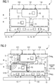
- Figure 1 shows schematically a mobile medical system 1 designed for autonomous or at least partially autonomous covering of distances in a schematic representation.
- the medical system 1 has a modular structure and comprises an in Figure 1 Carrier platform 3 shown in dashed lines for several network and communication-capable modules 10, 20, 30, 40, which are used for the mutual exchange of data with are designed according to wired or wireless interfaces.
- the carrier platform 3 represents the basis for a modular concept in which, for example, several different modules 10, 20, 30, 40 are arranged and interconnected in an interior area of the carrier platform 3 so that they can functionally communicate with one another.
- Figure 1 shows only a non-restrictive embodiment of this construction kit or module concept, ie the number and type of modules 10, 20, 30, 40 with which the carrier platform 3 is equipped, is generally "on demand", ie needs-based depending on the desired area of application , customized.
- the modules 10, 20, 30, 40 are in particular a base module 10, an environment detection module 20, an optionally optionally provided energy storage module 30 and a control module 40.
- the base module 10 with a chassis 12 and an, for example electric, drive 14 is located near the floor.
- the chassis 12 comprises a plurality of motor-driven or drivable drive means 16, which are designed as essentially cylindrical or barrel-shaped rolling bodies 18.
- the diameter of the rolling body 18 is not constant in advantageous embodiments, but rather has a crown such that the diameter decreases at least slightly in the direction of the axial ends of the respective rolling body 18.
- the rolling elements 18 are provided, for example, with a rubber, linoleum or plastic surface.
- Linoleum is advantageously antistatic, slightly fungicidal and bacteriostatic, ie it inhibits any bacterial growth.
- the cause is the permanent emission of small amounts of different aldehydes from the so-called linseed oil oxidation in air or from the oxidation reaction in the manufacturing process. For this reason, linoleum is often used as a floor covering in buildings with increased hygiene requirements, such as hospitals or medical practices.
- the barrel-shaped rolling bodies 18 can have a stainless steel construction in configurations which is designed to accommodate a roller, for example made of solid rubber.
- the stainless steel construction is designed so that plastic rollers can be used in these.
- the plastic rollers have, for example, a thermoplastic polyurethane tread. This facilitates the mobility or the displaceability of the carrier platform 3 or the medical system 1.
- the drive means 16 are arranged in a comparatively simple drive mechanism which enables movement on the rolling elements 18.
- Corners and edges of the rolling elements 18 are advantageously rounded in configurations.
- the simple geometric shape of the essentially barrel-shaped or cylindrical rolling elements 18 enables simple cleaning, in particular by means of common disinfecting chemicals.
- the carrier platform 3 is designed, for example, to carry an imaging device 100 (also: imaging modality), further medical equipment 102 and / or additional medical loads 104 and / or further receptacles or containers. These components can be fastened to the carrier platform 3, for example, by means of tensioning and / or clip quick-release fasteners.
- the medical system 1 can, for example be used to transport containers, in particular to transport surgical and / or surgical products or aids that are contaminated with body fluids.
- the containers can be releasably fastened to the carrier platform 3, for example, by means of quick-release fasteners and / or clip fasteners.
- the mobile medical system 1 further comprises the environment detection module 20 for detecting the environment, in particular the stationary environment and of stationary and / or moving objects in the environment of the medical system 1.
- the environment detection module 20 is also used to plan the route.
- the optional energy storage module 30 is used to supply the modules 10, 20, 30, 40 with energy, in particular electrical energy, and the control module 40 for controlling and / or regulating the locomotion, taking into account the environment of the medical system 1 and the, in particular, sensor-detected environment Energy or charge state of the energy storage module 30.
- the modules 10, 20, 30, 40 are designed to be capable of intercommunication and networks.
- the modules 10, 20, 30, 40 are provided with suitable interfaces which are designed for wireless or wired communication, in particular in real time.
- These interfaces include, for example, an internal bus system BS, which is implemented in particular by an Ethernet, a CAN bus or by another field bus system suitable for medical applications.
- the Ethernet, the CAN bus and / or the field bus system is real-time capable, so that the modules 10, 20, 30, 40 can communicate with one another in real time.
- the modules 10, 20, 30, 40 have one or more microchips, processors, controllers and / or other electronic components that are designed to carry out digital data operations.
- the modules 10, 20, 30, 40 also have memories, in particular non-volatile memories, and RAM, especially volatile RAM.
- Operating systems (OS) and / or further software packages, in particular in the respective non-volatile memory, are installed in configurations on all modules 10, 20, 30, 40.
- the modules 10, 20, 30, 40 are designed in configurations to exchange protocols, that is to say in particular to send and / or receive them.
- the modules 10, 20, 30, 40 are configured as electronic control devices or comprise one or more electronic control devices.
- the control devices are embedded in modules 10, 20, 30, 40, for example.
- the modules 10, 20, 30, 40 communicate with one another by means of a secure, real-time capable bus system BS, which supports diagnostic protocols and is also set up for wired or wireless communication with a further external network.
- BS secure, real-time capable bus system
- the modules 10, 20, 30, 40 are, for example, capable of self-diagnosis and are thus set up to store states about their mode of operation (for example error codes or error memory entries) in the respective memory or in an internal module error memory or in a memory area provided for storing errors.
- states about their mode of operation for example error codes or error memory entries
- the error codes or error memory entries can be read out via diagnostic programs or so-called diagnostic services, in particular by means of a so-called diagnostic scan tool.
- a so-called “P-code” tool can be used, which is used, for example, in the context of on-board diagnostics (OBD) in the automotive industry.
- the error codes or error memory entries are made with the help of an external evaluation unit, such as a laptop or Notebook, readable.
- the error codes or error memory entries can, for example, as a response to an external trigger that is transmitted to the respective module 10, 20, 30, 40 as part of a remote diagnosis and / or remote maintenance, to the external evaluation unit or to a base station that is in an external network is arranged, can be transmitted wirelessly or wired.
- the external trigger is, for example, a so-called diagnostic job that is sent by the external evaluation unit, in particular by a notebook or a diagnostic scan tool or the like, and is executed in the internal network of the medical system 1 or the modules 10, 20, 30, 40 becomes.
- the external network is implemented as a wireless network, for example.
- At least some of the intercommunication and network-capable modules 10, 20, 30, 40 are thus designed to communicate protocols not only over the internal network or the internal bus system, in particular in real time, but are also designed in such a way that protocols on the external network can be sent and received from there.
- the modules 10, 20, 30, 40 or the internal network or bus system BS have at least appropriately designed wireless or wired external interfaces ES.
- OTA over-the-air
- the internal network or bus system BS has, for example, at least one access port set up for remote diagnosis and / or remote maintenance to a cloud application.
- This enables in particular a comparison of internal status data, for example, actual data of the modular medical system 1 or of the modules 10, 20, 30, 40 "on board", with external standard data.
- the external standard data can be target data, for example, which are stored in particular in the external network of a hospital or a similar medical facility.
- status data of the imaging device 100 can be called up from a control center without having to send one or more service technicians into the immediate vicinity of the imaging device 100, which is time-consuming and costly.
- this also brings advantages with regard to the hygiene standards to be observed in a clinical environment.
- the base module 10 is essential for the mechanical movement of the medical system 1 or the carrier platform 3. It has no omnidirectional wheels, in particular no Mecanum wheels.
- the chassis 12 of the base module 10 has a comparatively simple mechanism which enables the medical system 1 to move on structurally simple, rolling rolling elements 18.
- the base module 10 has a vibration sensor system 11 which is designed to detect vibrations that arise when the medical system 1 is in motion.
- the vibration sensor system 11 comprises, for example, an acceleration sensor.
- the vibration sensor system 11 of the base module 10 is designed to detect vibrations that occur during a journey. Based on the recorded vibrations, conclusions can be drawn drawn on the condition of the road or the roadway.
- the chassis 12 of the base module 10 is controlled in the operation of the medical system 1 by the control module 40 by means of suitable travel control commands FB depending on the detected vibrations, for example in such a way that when leaving a flat surface or a flat floor surface B, the base module 10 automatically pauses or stops driving. In this way, for example, damage to the underside of the carrier platform 3 and / or the base module 10 due to an uneven surface structure can be avoided.
- the base module 10 forwards, for example, the data VD from the vibration sensor system 11 to the environment detection module 20 via the aforementioned bus communication.
- the data VD originating from the vibration sensor system 11 are passed on directly to the control module 40 by means of the internal bus system BS.
- the base module 10 has, for example, an acceleration sensor system 13 which is designed in particular to detect accelerations that occur while driving.
- this acceleration sensor system 13 comprises at least one acceleration sensor which, in particular, has a different structural shape than the acceleration sensor of the aforementioned vibration sensor system 11.
- the acceleration sensor system 13 of the base module 10 is designed in particular to detect when a journey stops or starts abruptly. This can be used as a measure of any collisions between the medical system 1 and other moving or immobile objects, such as people, objects, walls, walls or the like.
- the base module 10 is designed to forward the data BD from the acceleration sensor system 13 to the environment detection module 20 via the aforementioned bus communication.
- the base module 10 is designed to forward the data recorded by the acceleration sensor system 13 directly internally to the control module 40 by means of bus communication.
- the base module 10 has a discrete electrical diagnostic line Diag A , via which diagnostic protocols, in particular status monitoring of the base module 10, detected collisions, bad road detection or the like, can be passed on to the control module 40.
- no discrete diagnosis line is provided.
- the diagnostic protocols are sent and received, for example, via the bus communication described above, that is to say via the bus system BS.
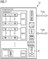
- FIG. 2 schematically illustrates the structure and the procedural interaction of the modules 10, 20, 30, 40 of the medical system 1.
- the base module 10 of the illustrated medical system 1 has a discrete diagnosis line Diag A.
- the poor road identification implemented via the acceleration sensor system 13 and / or via the vibration sensor system 11 is transmitted from the base module 10 as qualified raw data QRD by means of bus communication to the environment detection module 20 and further qualified there.
- the chassis 12 of the base module 10 comprises a plurality of independently controllable and / or drivable roller or barrel-shaped rolling elements 18 on which the mobile medical System 1 can move.
- the rolling elements 18 can be driven, for example, by means of an electric drive 14 in such a way that the drive axis of the electric drive 14 corresponds to the axis of rotation R of the respectively coupled rolling element 18. In this way, rolling bodies 18 with direct drive are implemented in configurations.
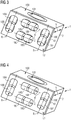
- FIGs 3, 4 and 5 illustrate by way of example running gears 12, each with eight roll bodies 18 that can be controlled and driven independently of one another.
- Figures 3 and 4 show, by way of example, a medical system 1 with an imaging device 100 designed as a computer tomograph (CT) and having a mobile gantry 101, in a perspective illustration.
- the rolling bodies 18 are each arranged in pairs along axes of rotation R in such a way that when the medical system 1 moves, they rotate while making contact with the ground and roll in a statically stable manner on the floor without tilting to the side.
- rollers shown represent the aforementioned barrel-shaped rolling elements 18 as an example.
- Each rolling element 18A, 18B, 18C, 18D, 18E, 18F, 18G, 18H can be driven and controlled individually.
- Each rolling body 18A, 18B, 18C, 18D, 18E, 18F, 18G, 18H has, for example, in its geometrical interior an electrical drive 14 which is non-rotatably connected to the base module 10 and is designed to provide a drive torque.
- the electric drive 14 can rotate in the opposite direction as well as, with appropriate control, in a clockwise direction.
- the rolling bodies 18A, 18B, 18C, 18D, 18E, 18F, 18G, 18H can rotate forwards and backwards.
- the rolling bodies 18A, 18B, 18C, 18D, 18E, 18F, 18G, 18H are each aligned in pairs along a respective axis of rotation R, so that four different axes of rotation R are formed.
- the axes of rotation R are, for example, arranged at right angles to one another, in particular in a rectangle or in a square, the axes of rotation R running parallel to side surfaces of the base module 10 or the carrier platform 3, for example.
- the chassis 12 accordingly comprises four travel axes for moving the medical system 1 forwards, backwards, to the right and to the left.
- the rolling bodies 18, 18A, 18B, 18C, 18D, 18E, 18F, 18G, 18H have in particular in the in Figure 3
- the embodiment shown does not have a constant diameter, but is curved so that only one contact point with a bottom surface B is formed, which is, for example, located in the center of the respective rolling body 18, 18A, 18B, 18C, 18D, 18E, 18F, 18G, 18H .
- a crown is in the rolling or.
- Storage technology a targeted barrel-like, for example central thickening of a roller or a rolling body.
- cylindrical, non-cambered rolling bodies 18 form contact lines with the floor surface B on which the medical system 1 moves. This results in increased rolling friction.
- Curved rolling bodies 18, 18A, 18B, 18C, 18D, 18E, 18F, 18G, 18H have less rolling friction and bring about an improved static determination with regard to the stability of the base module 10.
- Figure 4 shows an example of an embodiment with cylindrical rolling elements 18, 18A, 18B, 18C, 18D, 18E, 18F, 18G, 18H without a crown.
- FIG. 3 shows an exemplary embodiment of the mobile medical system 1, which carries a patient bed 103 as medical equipment 102.
- the basic module 10 with the independently controllable and drivable rolling elements 18, 18A, 18B, 18C, 18D, 18E, 18F, 18G, 18H corresponds essentially the one already referring to Figures 3 and 4 described execution.
- the base module 10 has a hygiene apron 17 running around the area close to the floor.
- the above-mentioned drive concept with eight independently controllable and drivable rolling elements 18, 18A, 18B, 18C, 18D, 18E, 18F, 18G, 18H is therefore equally suitable for an imaging device 100, in particular a mobile C-arm or a computer tomograph with gantry 101, or a patient bed 103.
- the medical system 1 can be moved as follows: If, for example, the rolling bodies 18A, 18B and / or the rolling bodies 18E, 18F (cf. in particular Figures 3 and 4 ) set in a rotary movement, the base module 10 moves in one direction, forwards or backwards - depending on the control of the electrical drives 14, which are located, for example, in the interior of the rolling bodies 18A, 18B, 18E, 18F. If, on the other hand, the rolling bodies 18G, 18H and / or the rolling bodies 18C, 18D are driven (cf. in particular Figures 3 and 4 ), the base module 10 moves in a lateral direction, corresponding to the activation of the electric drives 14.
- the base module 10 swivels to the left. If, on the other hand, only the two rollers 18A and 18F are driven (cf. in particular Figures 3 and 4 ), the base module 10 swivels to the right.
- the base module 10 with the rolling elements 18, 18A, 18B, 18C, 18D, 18E, 18F, 18G, 18H which can be driven and controlled independently of one another, can move in a particularly simple manner.
- no complex omnidirectional gears and, in particular, no complex Mecanum gears are required for this.
- one or more rolling elements 18, 18A, 18B, 18C, 18D, 18E, 18F, 18G, 18H is / are driven by an electric drive 14 via a transmission. In this way, an indirect drive is implemented.
- the rolling elements 18, 18A, 18B, 18C, 18D, 18E, 18F, 18G, 18H are retractable and extendable in the vertical direction.
- the rolling bodies 18A, 18B and / or the rolling bodies 18E, 18F are driven, for example. So that this driving maneuver is not adversely affected by the unneeded rolling bodies 18C, 18D, 18G, 18H, these rolling bodies 18C, 18V, 18G, 18H are retracted.
- an adjustment device 15, in particular a mechatronic adjustment device 15, is provided, which is designed to adjust the rolling bodies 18, 18A, 18B, 18C, 18D, 18E, 18F, 18G, 18H individually in the vertical direction V.
- the adjusting device 15 has, for example, a frame and an actuator.
- the rolling bodies 18, 18A, 18B, 18C, 18D, 18E, 18F, 18G, 18H are typically resiliently mounted, so that the spring deflection when the rolling bodies 18, 18A, 18B, 18C, 18D, 18E, 18F, 18G, 18H are retracted shortened in the vertical direction V.
- the adjustment device 15 is, for example, an adjustable shock absorber which is designed as a spring travel adjuster.
- the adjustment device 15 is designed, for example, for the electrical, hydraulic or pneumatic adjustment of the rolling bodies 18, 18A, 18B, 18C, 18D, 18E, 18F, 18G, 18H.
- the adjusting device 15 is realized by a controllable gas pressure shock absorber.
- the rolling element 18, 18A, 18B, 18C, 18D, 18E, 18F, 18G, 18H can be moved between a first position in which the rolling element 18, 18A, 18B, 18C, 18D, 18E, 18F, 18G, 18H has contact with the floor surface B, and a second position in which the rolling body 18, 18A, 18B, 18C, 18D, 18E, 18F, 18G, 18H is spaced from the floor surface B in the vertical direction V, are moved.
- each of the independently controllable rolling bodies 18, 18A, 18B, 18C, 18D, 18E, 18F, 18G, 18H can be adjusted in the vertical direction via an adjustment device 15.
- each rolling body 18, 18A, 18B, 18C, 18D, 18E, 18F, 18G, 18H can be in operative connection with the base module 10 via a separate, adjustable shock absorber.
- the environment detection module 20 (also: sensor base) comprises an environment sensor system 21 with several transmitters and / or sensors and / or further sensors.
- the environment sensor system 21 is designed to detect the environment of the medical system 1.
- the environment detection module 20 has environment sensors that can detect the environment, which changes dynamically while driving.
- the environmental sensors of the environmental sensor system 21 can have different designs and are designed, for example, as near-field radar sensors, far-field radar sensors, LIDAR (light detection and ranging) sensors or laser-scanning sensor elements, preferably in combination with a video and / or camera sensor system.
- ultrasound sensors for example, are alternatively or additionally provided, which are arranged on the environment detection module 20 or are at least electrically connected to the environment detection module 20.
- the environment sensor system 21 of the environment detection module 20 is able, through the interaction of several such sensors and / or sensor elements, to detect both dynamically moving and stationary people and objects as environmental information or raw data RD.
- These raw data RD (see in particular Figure 2 ) are passed on internally to the environment detection module 20 or further processed there.
- an operating system (OS) is operated within the environment detection module 20.
- the operating system enables image recognition software to run within the environment detection module 20, for example. This image recognition software is used to qualify the raw data, ie the dynamic and stationary detection of objects, in particular of people and objects, in the vicinity of the medical system 1 results in the actual detection of People and objects.
- the recognized people and objects can then be passed on to the control module 40 as qualified environment data QUD, in particular in such a way that a virtual image of the environment can be created in the control module 40, with the aim of collision-free route planning for the route and the direction of travel of the medical System 1 to provide.
- the medical system 1 has configurations (cf. in particular Figure 2 ) a discrete electrical diagnosis line Diag s , via which diagnosis protocols (eg error pattern detection, collision detection) can be transmitted to the control module 40 (also: control base).
- diagnosis protocols eg error pattern detection, collision detection
- the diagnostic protocols are, for example, based on the one described above Bus communication, i.e. via the bus system BS, sent and received.
- FIG. 6 shows a possible embodiment of a medical system 1 with an environment detection module 20 having an environment sensor system 21.
- the environment sensor system 21 comprises cameras 22 which are directed forward in the direction of travel and have an essentially conical detection area EK.
- the environment sensor system 21 further comprises near-field radar sensors 23 and far-field radar sensors 24, which are directed forward in the direction of travel and rearward counter to the direction of travel.
- the near-field radar sensors 23 have essentially conical detection areas EN.
- the far-field radar sensors 24 have essentially conical detection areas EF with a greater range.
- the near-field radar sensors 23 are, for example, 24 GHz radar sensors.
- the far-field radar sensors 24 are, for example, 77 GHz radar sensors.
- The, in particular optionally provided, energy storage module 30 (also: supply base) is in one possible embodiment in Figure 7 shown.
- the energy storage module 30 is used in particular to ensure the autonomy or self-sufficiency of stationary supply networks.
- the energy storage module 30 provides the power and voltage supply for the modules 10, 20, 30 and for this purpose has several energy cells 31 for storing electrical energy.
- the energy storage module 30 is connected to the power supply with the modules 10, 20, 30 and the optionally available imaging device 100 via electrical lines L.
- the energy cells 31 are designed, for example, as batteries or accumulators and also have an internal control and regulation system, a so-called Battery or accumulator management system BMS.
- the battery management system BMS is designed in particular to monitor the state-of-charge (SOC) and the availability state (English: state-of-health, SOH) of the energy cells 31, preferably in real time, so that internal and current information about a remaining running time of the energy storage module 30 is always available.
- SOC state-of-charge
- SOH availability state-of-health
- the state of charge can, as in particular in Figure 2 are used in a method for operating the medical system 1 to transmit real-time information about the remaining capacity of the energy cells 31 of the energy storage module 30 to the control module 40.
- the communication of the energy storage module 30 with the control module 40 takes place via a dedicated or discrete diagnosis line Diag E or via the bus communication already described, which is provided by the bus system BS.
- the availability state is a measure of the ability of the energy cells 31 “on board” to deliver their specified output. This is particularly important for assessing the readiness of emergency power devices and an indicator of whether maintenance measures, in particular within the scope of the aforementioned predictive maintenance, are required.
- the battery management system BMS is designed in embodiments to implement a method for cell protection. This cell protection is used to comply with the design limits of the energy cells 31. Operating an energy cell 31 outside the specified design limits generally leads to failure of the corresponding energy cell 31 and thus to additional costs for a required battery change.
- the energy storage module 30 has further communication interfaces which enable a user or the control module 40 to access, in particular to change control parameters of the battery management system BMS or to carry out a diagnosis or a test of the energy storage module 30.
- Diagnostic protocols can be passed on to control module 40 during operation of medical system 1 via the discrete electrical diagnostic line Diag E. In alternative configurations to this, no discrete diagnosis line is provided. In this case, the diagnostic protocols are sent and received, for example, via the bus communication described above or via the internal bus system BS.
- the energy storage module 30 comprises, for example, energy cells 31 which are designed as nickel-metal hydride (NiMH) batteries.
- the energy cells 31 are designed, for example, as AGM batteries, as lithium-ion batteries (LiB) or as lithium-polymer accumulators (LiPo).
- the energy cells 31 are arranged, for example, in parallel and series connection and advantageously divided into cell packets or modules and submodules.
- the energy storage module 30 comprises a fuel cell, in particular a fuel cell that can be operated with methanol, butane or the like.
- a control and / or an energy management system of the fuel cell is preferably implemented in these configurations of the energy storage module 30.
- Such an energy storage module 30 is designed, in particular, to be energy self-sufficient in a field environment such as a field hospital in a war or disaster area. In these cases, energy self-sufficiency can offer decisive advantages with regard to the availability of the medical system 1.
- the energy storage module 30 has, in addition to the battery management system BMS, alternatives to commercially available accumulators or batteries with a high energy density.
- the energy storage module 30 has a lithium-air battery as an energy store.
- Such energy storage devices can have an energy density that is 5 to 10 times higher than that of conventional lithium-ion batteries.
- the energy storage module 30 has, for example, a silicon-based accumulator which comprises anodes made of pure silicon. Compared to the common lithium-ion technology, such an energy storage device can have an energy density that is ten times higher, for example.
- the energy storage module 30 has, for example, so-called lithium iron phosphate batteries (LiFeP batteries) or lithium titanate batteries (Li-Ti batteries). Since the titanate cannot react with oxides from the negative electrode, thermal runaway of the battery can be prevented with such a design, possibly even if mechanical damage is present.
- a lithium titanate battery can advantageously be operated at low temperatures, for example in a temperature range from -40 ° C to +55 ° C.
- the energy storage module 30 comprises a so-called redox flow battery (RFB), for example in the form of a vanadium redox accumulator, a sodium bromide redox accumulator or a zinc-bromine accumulator, as an energy store.
- RFB redox flow battery
- the energy storage module 30 comprises a so-called solid-state battery (also: solid-state accumulator) as an energy store.
- solid-state battery also: solid-state accumulator
- Such designs have increased safety, since in solid batteries of this type both electrodes and the electrolyte are made of solid material.
- Such a solid-state battery is particularly in comparison to conventional lithium-ion accumulators only relatively flame retardant.
- the flammability of the energy store used can play an important role.
- the control module 40 (also: control module, control basis) is designed to internally process and / or qualify data or information from the environment detection module 20, to convert them into travel control commands FB and to pass them on to the base module 10.
- the control module 40 is also for the acquisition, processing and realization of user interactions as well as for system monitoring, calibration, interconnectivity with clinical IT systems, such as a hospital information system (HIS), a laboratory information system (LIS) or a so-called picture archiving or Communication System (PACS) and data security monitoring responsible.
- HIS hospital information system
- LIS laboratory information system
- PACS picture archiving or Communication System
- control module 40 has a user interface 41 that includes, for example, input devices such as a touchscreen, a keyboard or a device that is designed to record and recognize gestures by the user and / or voice commands.
- input devices such as a touchscreen, a keyboard or a device that is designed to record and recognize gestures by the user and / or voice commands.
- the control module 40 is designed, for example, to implement the following functions: function example User interactions Motorized support of movements Voice and gesture controls System monitoring Predictive maintenance Condition monitoring, self-diagnosis and error display calibration (Semi-) autonomous in-situ calibration routines (e.g. localization and navigation tasks, wear detection) Data security monitoring Data security, data integrity (e.g. checksums) Data protection (e.g. PKI methods)
- the control module 40 comprises high-performance regulation and control electronics in order to enable the partially autonomous or autonomous operation of the medical system 1 or the carrier platform 3.
- An operating system (OS) is installed within the control module 40 in configurations, such as, for example, also in the other modules 10, 20, 30.
- the operating system of the control module 40 enables the installation of further software.
- route planning or navigation software is implemented within the control module 40.
- the route planning or navigation in a method for operating the medical system 1 takes place as a function of the qualified environment data QUD, in particular as a function of the persons and objects detected and recognized by sensors, for example in such a way that a virtual image of the environment is created in the control module 40.
- the purpose of the virtual image of the environment is to provide collision-free route planning for the route and the direction of travel of the mobile medical system 1 or the carrier platform 3.
- control module 40 transmits travel control commands FB to the base module 10 for controlling the drive means 16, for example as a function of the virtual image of the environment.
- the control module 40 is designed to: to regulate the movement of the medical system 1 and in particular to take into account the environment and / or the energy state of the energy storage module 30, which is determined, for example, as mentioned above by the battery management system BMS of the energy storage module 30 and made available to the control module 40 via the bus system BS.
- Some exemplary travel control commands FB may relate to a forward, backward, left pan (45 degrees), right pan (45 degrees), starboard (left direction), port (right direction) movement.
- control module 40 has what is known as voice assistance functionality and, in particular, software designed for this purpose, as well as a user interface 41 that is designed to capture human speech.
- user interface 41 has, for example, microphones or the like.
- the speech recognition software is designed to recognize at least one language.
- voice assistance software By means of such voice assistance software, it is possible for people, such as doctors, clinic staff, medical-technical assistants (MTA), to issue voice commands which the voice assistance function can detect and recognize as such.
- the voice commands can, for example, be identical to the aforementioned travel control commands FB and consist, for example, of words such as "forward”, “left swivel 45" (degrees), “right swivel 45” (degrees), “backwards", “left” (starboard), pronounced “right” (port) aloud.
- the execution of one of the driving control commands FB by the base module 10 includes, for example, the adjustment of at least one of the rolling bodies 18, 18A, 18B, 18C, 18D, 18E, 18F, 18G, 18H in the vertical direction V so that the corresponding driving maneuver can be carried out.
- the voice commands or spoken commands are processed within the control module 40 with priority over the drive control commands FB generated internally using the virtual image, so that as a result the user (MTA, doctor, clinic staff) can see the movement of the medical system 1 in Can control refinements completely on the basis of spoken commands, instead of having to rely on the travel control commands FB generated by the control module 40.
- control via spoken commands can be viewed as “partially autonomous” operation of the medical system 1.
- the control module 40 advantageously has a control device gateway, i.e. a qualified data and / or communication interface for network communication between the internal bus system BS and an external network, for example a wireless network or a "cloud".
- a control device gateway i.e. a qualified data and / or communication interface for network communication between the internal bus system BS and an external network, for example a wireless network or a "cloud”.
- an external network for example a wireless network or a "cloud”.
- over-the-air updates of individual software packages can be downloaded from the external network.
- the importing of future software updates can be offered as a service in an advantageous manner.
- the invention also relates to the advantageous technical interaction and control method of the aforementioned modules 10, 20, 30, 40.
- the medical system 1 comprises the base module 10, the environment detection module 20 and the control module 40, optionally also the energy storage module 30, in order to be autonomous or at least partially to enable autonomous movement of the medical system 1 from one location (for example a hospital, a medical center, a practice, a field hospital, etc.) to a further / next location that is different from the first location.
- one location for example a hospital, a medical center, a practice, a field hospital, etc.
Landscapes
- Health & Medical Sciences (AREA)
- Life Sciences & Earth Sciences (AREA)
- Engineering & Computer Science (AREA)
- Medical Informatics (AREA)
- General Health & Medical Sciences (AREA)
- Public Health (AREA)
- Veterinary Medicine (AREA)
- Animal Behavior & Ethology (AREA)
- Biomedical Technology (AREA)
- Physics & Mathematics (AREA)
- Surgery (AREA)
- Radiology & Medical Imaging (AREA)
- Heart & Thoracic Surgery (AREA)
- Molecular Biology (AREA)
- Nuclear Medicine, Radiotherapy & Molecular Imaging (AREA)
- Biophysics (AREA)
- Pathology (AREA)
- Optics & Photonics (AREA)
- High Energy & Nuclear Physics (AREA)
- Mechanical Engineering (AREA)
- Nursing (AREA)
- Signal Processing (AREA)
- Computer Networks & Wireless Communication (AREA)
- Business, Economics & Management (AREA)
- Primary Health Care (AREA)
- Computing Systems (AREA)
- General Physics & Mathematics (AREA)
- Pulmonology (AREA)
- Theoretical Computer Science (AREA)
- Epidemiology (AREA)
- General Business, Economics & Management (AREA)
- Apparatus For Radiation Diagnosis (AREA)
- Manipulator (AREA)
Priority Applications (3)
| Application Number | Priority Date | Filing Date | Title |
|---|---|---|---|
| EP19216765.8A EP3838245A1 (fr) | 2019-12-17 | 2019-12-17 | Module de base, système médical et procédé de fonctionnement du système médical |
| US17/113,323 US11723824B2 (en) | 2019-12-17 | 2020-12-07 | Base module, medical system and method for operation of the medical system |
| CN202011483456.XA CN112971817A (zh) | 2019-12-17 | 2020-12-16 | 基础模块、医学系统和用于运行医学系统的方法 |
Applications Claiming Priority (1)
| Application Number | Priority Date | Filing Date | Title |
|---|---|---|---|
| EP19216765.8A EP3838245A1 (fr) | 2019-12-17 | 2019-12-17 | Module de base, système médical et procédé de fonctionnement du système médical |
Publications (1)
| Publication Number | Publication Date |
|---|---|
| EP3838245A1 true EP3838245A1 (fr) | 2021-06-23 |
Family
ID=68917749
Family Applications (1)
| Application Number | Title | Priority Date | Filing Date |
|---|---|---|---|
| EP19216765.8A Ceased EP3838245A1 (fr) | 2019-12-17 | 2019-12-17 | Module de base, système médical et procédé de fonctionnement du système médical |
Country Status (3)
| Country | Link |
|---|---|
| US (1) | US11723824B2 (fr) |
| EP (1) | EP3838245A1 (fr) |
| CN (1) | CN112971817A (fr) |
Families Citing this family (1)
| Publication number | Priority date | Publication date | Assignee | Title |
|---|---|---|---|---|
| WO2022136077A1 (fr) * | 2020-12-22 | 2022-06-30 | Koninklijke Philips N.V. | Rétroaction de données d'auto-test de système ultrasonore destinée à une analyse de tendance de système |
Citations (6)
| Publication number | Priority date | Publication date | Assignee | Title |
|---|---|---|---|---|
| US4605086A (en) * | 1983-11-03 | 1986-08-12 | Itshak Marom | Lifting and maneuvering device for motor vehicles |
| US20080123818A1 (en) * | 2006-11-23 | 2008-05-29 | General Electric Company | Systems, methods and apparatus of wheels for lateral motion of mobile c-arm x-ray devices |
| DE102014208463A1 (de) | 2014-05-06 | 2015-11-12 | Siemens Aktiengesellschaft | Patientenliege mit einem Steuerungssystem und Verfahren zum Steuern einer Patientenliege |
| DE102014115901A1 (de) | 2014-10-31 | 2016-05-04 | MAQUET GmbH | Operationstisch und Bodenplattform für einen Operationstisch |
| US20180242932A1 (en) | 2017-02-28 | 2018-08-30 | NeuroLogica Corporation, a subsidiary of Samsung Electronics Co., Ltd. | Mobile anatomical imaging system with improved movement system |
| DE102011083876B4 (de) | 2011-09-30 | 2018-12-27 | Siemens Healthcare Gmbh | Verfahren zur Bewegungssteuerung einer Röntgenvorrichtung und Röntgensystem |
Family Cites Families (16)
| Publication number | Priority date | Publication date | Assignee | Title |
|---|---|---|---|---|
| US3876255A (en) | 1972-11-13 | 1975-04-08 | Ilon B E | Wheels for a course stable selfpropelling vehicle movable in any desired direction on the ground or some other base |
| KR20120054409A (ko) * | 2010-11-19 | 2012-05-30 | 삼성메디슨 주식회사 | 이동형 초음파진단장치 및 그 제어방법 |
| US20140094997A1 (en) * | 2012-09-28 | 2014-04-03 | Elwha Llc | Automated Systems, Devices, and Methods for Transporting and Supporting Patients Including Multi-Floor Operation |
| EP2967470B1 (fr) * | 2013-03-15 | 2020-10-21 | Mobius Imaging, Llc | Système de roulette pour appareil mobile |
| CN105705095B (zh) * | 2013-09-06 | 2019-10-08 | 株式会社岛津制作所 | 移动式x射线摄影装置 |
| DE102014202033B4 (de) * | 2014-02-05 | 2017-07-06 | Siemens Healthcare Gmbh | Mobiles medizinisches Gerät sowie Verfahren zur Steuerung einer Bewegung des mobilen medizinischen Geräts |
| DE102014202024A1 (de) * | 2014-02-05 | 2015-08-06 | Siemens Aktiengesellschaft | Medizinische Vorrichtung |
| US11058378B2 (en) * | 2016-02-03 | 2021-07-13 | Globus Medical, Inc. | Portable medical imaging system |
| DE102016208123B4 (de) | 2016-05-11 | 2020-03-19 | Siemens Healthcare Gmbh | Verfahren und System zum Ausführen einer Scanbewegung einer Bildgebungsdaten-Akquisitionseinheit |
| DE102016212077A1 (de) * | 2016-07-04 | 2018-01-04 | Siemens Healthcare Gmbh | Verfahren zum Betrieb einer wenigstens teilweise autonom bewegten, mobilen medizintechnischen Einheit und mobile medizintechnische Einheit |
| US10051718B2 (en) | 2016-08-03 | 2018-08-14 | Samsung Electronics Co., Ltd. | Mobile X-ray apparatus and method of operating the same |
| DE102017220500B4 (de) * | 2017-11-16 | 2024-07-18 | Siemens Healthineers Ag | System und Verfahren zur Unterstützung einer medizinischen Maßnahme |
| DE102018211669B4 (de) | 2018-07-12 | 2020-01-23 | Siemens Healthcare Gmbh | Omnidirektionales Fahrwerk für eine Gantry eines Computertomographiegeräts |
| DE202019102172U1 (de) | 2019-04-16 | 2019-04-29 | Siemens Healthcare Gmbh | Radanordnung |
| DE102019209543A1 (de) | 2019-06-28 | 2020-09-17 | Siemens Healthcare Gmbh | Verfahren zum Bereitstellen einer Kollisionsinformation und medizinische Bildgebungsvorrichtung |
| EP3851050B1 (fr) | 2020-01-16 | 2025-07-16 | Siemens Healthineers AG | Plateforme mobile |
-
2019
- 2019-12-17 EP EP19216765.8A patent/EP3838245A1/fr not_active Ceased
-
2020
- 2020-12-07 US US17/113,323 patent/US11723824B2/en active Active
- 2020-12-16 CN CN202011483456.XA patent/CN112971817A/zh active Pending
Patent Citations (6)
| Publication number | Priority date | Publication date | Assignee | Title |
|---|---|---|---|---|
| US4605086A (en) * | 1983-11-03 | 1986-08-12 | Itshak Marom | Lifting and maneuvering device for motor vehicles |
| US20080123818A1 (en) * | 2006-11-23 | 2008-05-29 | General Electric Company | Systems, methods and apparatus of wheels for lateral motion of mobile c-arm x-ray devices |
| DE102011083876B4 (de) | 2011-09-30 | 2018-12-27 | Siemens Healthcare Gmbh | Verfahren zur Bewegungssteuerung einer Röntgenvorrichtung und Röntgensystem |
| DE102014208463A1 (de) | 2014-05-06 | 2015-11-12 | Siemens Aktiengesellschaft | Patientenliege mit einem Steuerungssystem und Verfahren zum Steuern einer Patientenliege |
| DE102014115901A1 (de) | 2014-10-31 | 2016-05-04 | MAQUET GmbH | Operationstisch und Bodenplattform für einen Operationstisch |
| US20180242932A1 (en) | 2017-02-28 | 2018-08-30 | NeuroLogica Corporation, a subsidiary of Samsung Electronics Co., Ltd. | Mobile anatomical imaging system with improved movement system |
Also Published As
| Publication number | Publication date |
|---|---|
| US20210177683A1 (en) | 2021-06-17 |
| US11723824B2 (en) | 2023-08-15 |
| CN112971817A (zh) | 2021-06-18 |
Similar Documents
| Publication | Publication Date | Title |
|---|---|---|
| EP3415070B1 (fr) | Système pourvu d'au moins deux dispositifs de traitement du sol | |
| DE202020104652U1 (de) | Patientenliege für eine medizinische Bildgebungsanlage | |
| EP3388295B1 (fr) | Procédé de fonctionnement d'un système de transport ainsi que système de transport correspondant | |
| DE102013213379A1 (de) | Vorrichtung und Verfahren zur Unterstützung eines Fahrers beim Ein- und Ausparken seines Fahrzeugs in einer Parkeinrichtung | |
| DE102012112035A1 (de) | Verfahren zum Betrieb eines Staubsaugerroboters und nach dem Verfahren arbeitender Staubsaugerroboter sowie System mit einem solchen Staubsaugerroboter | |
| EP3559773B1 (fr) | Procédé de navigation et localisation automatique d'un appareil d'usinage à déplacement autonome | |
| DE112021002948B4 (de) | Unabhängiges robotersicherheitssystem mit einer sicherheitsbewerteten sps | |
| US20250346273A1 (en) | Cart | |
| WO2023274689A1 (fr) | Système robotique modulaire et procédé de transport d'un objet | |
| DE102016011768A1 (de) | Batteriesystem mit bidirektionaler drahtloser Kommunikation | |
| EP3838245A1 (fr) | Module de base, système médical et procédé de fonctionnement du système médical | |
| EP3915831A1 (fr) | Attelage et véhicule tracté doté d'un dispositif de traitement du signal | |
| DE202016004708U1 (de) | Modulares Fahrzeug- und Logistiksystem zum hoch-automatisierten Transport, Austausch und Übergabe von Waren, Paketen und Gütern innerhalb von und zwischen Fahrzeugen, Warensendern und -empfängern | |
| EP3957524A1 (fr) | Système intralogistique pourvu de véhicules autonomes et/ou automatisés et stations de nettoyage pour capteurs de véhicule, ainsi que procédés de commande du système | |
| DE102020212464A1 (de) | Modulares Robotersystem zum Transportieren eines Objektes und Verfahren zum Transportieren eines Objektes | |
| DE112020002438T5 (de) | Stromversorgungssystem und stromversorgungseinrichtung | |
| EP3452255A1 (fr) | Système de mesure mobile | |
| DE102016222016B4 (de) | Verfahren zur Überwachung eines Roboters und Steuereinheit | |
| DE102019202558A1 (de) | Unbemanntes bodengebundenes transportfahrzeug und verfahren zum transportieren von kabinenmonumenten | |
| DE202023103766U1 (de) | Mobile medizinische Patientenliege | |
| DE102019218112A1 (de) | Transportvorrichtung für ein Parksystem zum Positionieren eines Kraftfahrzeugs und Verfahren zum Betreiben einer Transportvorrichtung | |
| DE102016216162B4 (de) | Medizintechnisches System | |
| DE102016216210A1 (de) | Roboterfahrzeug, insbesondere für eine Automatisierungsanlage sowie eine Automatisierungsanlage mit dem Roboterfahrzeug | |
| DE102018109449A1 (de) | Fahrerloses Bodenfahrzeug zur Förderung von Lasten wie Fahrzeugkarosserien oder/und Fahrzeugteilen sowie Verfahren zum Transportieren einer solchen Last | |
| DE102016010664A1 (de) | Verfahren zur Positionierung von Batterien in Elektrofahrzeugen |
Legal Events
| Date | Code | Title | Description |
|---|---|---|---|
| PUAI | Public reference made under article 153(3) epc to a published international application that has entered the european phase |
Free format text: ORIGINAL CODE: 0009012 |
|
| STAA | Information on the status of an ep patent application or granted ep patent |
Free format text: STATUS: THE APPLICATION HAS BEEN PUBLISHED |
|
| AK | Designated contracting states |
Kind code of ref document: A1 Designated state(s): AL AT BE BG CH CY CZ DE DK EE ES FI FR GB GR HR HU IE IS IT LI LT LU LV MC MK MT NL NO PL PT RO RS SE SI SK SM TR |
|
| STAA | Information on the status of an ep patent application or granted ep patent |
Free format text: STATUS: REQUEST FOR EXAMINATION WAS MADE |
|
| 17P | Request for examination filed |
Effective date: 20211220 |
|
| RBV | Designated contracting states (corrected) |
Designated state(s): AL AT BE BG CH CY CZ DE DK EE ES FI FR GB GR HR HU IE IS IT LI LT LU LV MC MK MT NL NO PL PT RO RS SE SI SK SM TR |
|
| STAA | Information on the status of an ep patent application or granted ep patent |
Free format text: STATUS: EXAMINATION IS IN PROGRESS |
|
| 17Q | First examination report despatched |
Effective date: 20230724 |
|
| RAP1 | Party data changed (applicant data changed or rights of an application transferred) |
Owner name: SIEMENS HEALTHINEERS AG |
|
| STAA | Information on the status of an ep patent application or granted ep patent |
Free format text: STATUS: THE APPLICATION HAS BEEN REFUSED |
|
| 18R | Application refused |
Effective date: 20251110 |