EP3838320A1 - Belüftungsvorrichtung - Google Patents
Belüftungsvorrichtung Download PDFInfo
- Publication number
- EP3838320A1 EP3838320A1 EP18930080.9A EP18930080A EP3838320A1 EP 3838320 A1 EP3838320 A1 EP 3838320A1 EP 18930080 A EP18930080 A EP 18930080A EP 3838320 A1 EP3838320 A1 EP 3838320A1
- Authority
- EP
- European Patent Office
- Prior art keywords
- oxygen sensor
- ventilation apparatus
- paramagnetic oxygen
- housing
- buffer
- Prior art date
- Legal status (The legal status is an assumption and is not a legal conclusion. Google has not performed a legal analysis and makes no representation as to the accuracy of the status listed.)
- Granted
Links
Images






Classifications
-
- A—HUMAN NECESSITIES
- A61—MEDICAL OR VETERINARY SCIENCE; HYGIENE
- A61B—DIAGNOSIS; SURGERY; IDENTIFICATION
- A61B5/00—Measuring for diagnostic purposes; Identification of persons
- A61B5/08—Measuring devices for evaluating the respiratory organs
- A61B5/087—Measuring breath flow
-
- A—HUMAN NECESSITIES
- A61—MEDICAL OR VETERINARY SCIENCE; HYGIENE
- A61B—DIAGNOSIS; SURGERY; IDENTIFICATION
- A61B5/00—Measuring for diagnostic purposes; Identification of persons
- A61B5/08—Measuring devices for evaluating the respiratory organs
- A61B5/083—Measuring rate of metabolism by using breath test, e.g. measuring rate of oxygen consumption
-
- A—HUMAN NECESSITIES
- A61—MEDICAL OR VETERINARY SCIENCE; HYGIENE
- A61B—DIAGNOSIS; SURGERY; IDENTIFICATION
- A61B5/00—Measuring for diagnostic purposes; Identification of persons
- A61B5/08—Measuring devices for evaluating the respiratory organs
- A61B5/097—Devices for facilitating collection of breath or for directing breath into or through measuring devices
-
- A—HUMAN NECESSITIES
- A61—MEDICAL OR VETERINARY SCIENCE; HYGIENE
- A61M—DEVICES FOR INTRODUCING MEDIA INTO, OR ONTO, THE BODY; DEVICES FOR TRANSDUCING BODY MEDIA OR FOR TAKING MEDIA FROM THE BODY; DEVICES FOR PRODUCING OR ENDING SLEEP OR STUPOR
- A61M16/00—Devices for influencing the respiratory system of patients by gas treatment, e.g. ventilators; Tracheal tubes
- A61M16/0003—Accessories therefor, e.g. sensors, vibrators, negative pressure
-
- A—HUMAN NECESSITIES
- A61—MEDICAL OR VETERINARY SCIENCE; HYGIENE
- A61M—DEVICES FOR INTRODUCING MEDIA INTO, OR ONTO, THE BODY; DEVICES FOR TRANSDUCING BODY MEDIA OR FOR TAKING MEDIA FROM THE BODY; DEVICES FOR PRODUCING OR ENDING SLEEP OR STUPOR
- A61M16/00—Devices for influencing the respiratory system of patients by gas treatment, e.g. ventilators; Tracheal tubes
- A61M16/021—Devices for influencing the respiratory system of patients by gas treatment, e.g. ventilators; Tracheal tubes operated by electrical means
- A61M16/022—Control means therefor
- A61M16/024—Control means therefor including calculation means, e.g. using a processor
-
- A—HUMAN NECESSITIES
- A61—MEDICAL OR VETERINARY SCIENCE; HYGIENE
- A61M—DEVICES FOR INTRODUCING MEDIA INTO, OR ONTO, THE BODY; DEVICES FOR TRANSDUCING BODY MEDIA OR FOR TAKING MEDIA FROM THE BODY; DEVICES FOR PRODUCING OR ENDING SLEEP OR STUPOR
- A61M16/00—Devices for influencing the respiratory system of patients by gas treatment, e.g. ventilators; Tracheal tubes
- A61M16/10—Preparation of respiratory gases or vapours
- A61M16/1005—Preparation of respiratory gases or vapours with O2 features or with parameter measurement
-
- G—PHYSICS
- G01—MEASURING; TESTING
- G01N—INVESTIGATING OR ANALYSING MATERIALS BY DETERMINING THEIR CHEMICAL OR PHYSICAL PROPERTIES
- G01N33/00—Investigating or analysing materials by specific methods not covered by groups G01N1/00 - G01N31/00
- G01N33/0004—Gaseous mixtures, e.g. polluted air
- G01N33/0009—General constructional details of gas analysers, e.g. portable test equipment
- G01N33/0027—General constructional details of gas analysers, e.g. portable test equipment concerning the detector
- G01N33/0036—General constructional details of gas analysers, e.g. portable test equipment concerning the detector specially adapted to detect a particular component
-
- A—HUMAN NECESSITIES
- A61—MEDICAL OR VETERINARY SCIENCE; HYGIENE
- A61M—DEVICES FOR INTRODUCING MEDIA INTO, OR ONTO, THE BODY; DEVICES FOR TRANSDUCING BODY MEDIA OR FOR TAKING MEDIA FROM THE BODY; DEVICES FOR PRODUCING OR ENDING SLEEP OR STUPOR
- A61M16/00—Devices for influencing the respiratory system of patients by gas treatment, e.g. ventilators; Tracheal tubes
- A61M16/0057—Pumps therefor
- A61M16/0066—Blowers or centrifugal pumps
-
- A—HUMAN NECESSITIES
- A61—MEDICAL OR VETERINARY SCIENCE; HYGIENE
- A61M—DEVICES FOR INTRODUCING MEDIA INTO, OR ONTO, THE BODY; DEVICES FOR TRANSDUCING BODY MEDIA OR FOR TAKING MEDIA FROM THE BODY; DEVICES FOR PRODUCING OR ENDING SLEEP OR STUPOR
- A61M16/00—Devices for influencing the respiratory system of patients by gas treatment, e.g. ventilators; Tracheal tubes
- A61M16/08—Bellows; Connecting tubes ; Water traps; Patient circuits
- A61M16/0816—Joints or connectors
- A61M16/0841—Joints or connectors for sampling
- A61M16/085—Gas sampling
-
- A—HUMAN NECESSITIES
- A61—MEDICAL OR VETERINARY SCIENCE; HYGIENE
- A61M—DEVICES FOR INTRODUCING MEDIA INTO, OR ONTO, THE BODY; DEVICES FOR TRANSDUCING BODY MEDIA OR FOR TAKING MEDIA FROM THE BODY; DEVICES FOR PRODUCING OR ENDING SLEEP OR STUPOR
- A61M16/00—Devices for influencing the respiratory system of patients by gas treatment, e.g. ventilators; Tracheal tubes
- A61M16/0003—Accessories therefor, e.g. sensors, vibrators, negative pressure
- A61M2016/0015—Accessories therefor, e.g. sensors, vibrators, negative pressure inhalation detectors
- A61M2016/0018—Accessories therefor, e.g. sensors, vibrators, negative pressure inhalation detectors electrical
- A61M2016/0024—Accessories therefor, e.g. sensors, vibrators, negative pressure inhalation detectors electrical with an on-off output signal, e.g. from a switch
-
- A—HUMAN NECESSITIES
- A61—MEDICAL OR VETERINARY SCIENCE; HYGIENE
- A61M—DEVICES FOR INTRODUCING MEDIA INTO, OR ONTO, THE BODY; DEVICES FOR TRANSDUCING BODY MEDIA OR FOR TAKING MEDIA FROM THE BODY; DEVICES FOR PRODUCING OR ENDING SLEEP OR STUPOR
- A61M16/00—Devices for influencing the respiratory system of patients by gas treatment, e.g. ventilators; Tracheal tubes
- A61M16/10—Preparation of respiratory gases or vapours
- A61M16/1005—Preparation of respiratory gases or vapours with O2 features or with parameter measurement
- A61M2016/102—Measuring a parameter of the content of the delivered gas
- A61M2016/1025—Measuring a parameter of the content of the delivered gas the O2 concentration
-
- A—HUMAN NECESSITIES
- A61—MEDICAL OR VETERINARY SCIENCE; HYGIENE
- A61M—DEVICES FOR INTRODUCING MEDIA INTO, OR ONTO, THE BODY; DEVICES FOR TRANSDUCING BODY MEDIA OR FOR TAKING MEDIA FROM THE BODY; DEVICES FOR PRODUCING OR ENDING SLEEP OR STUPOR
- A61M2202/00—Special media to be introduced, removed or treated
- A61M2202/02—Gases
- A61M2202/0208—Oxygen
-
- A—HUMAN NECESSITIES
- A61—MEDICAL OR VETERINARY SCIENCE; HYGIENE
- A61M—DEVICES FOR INTRODUCING MEDIA INTO, OR ONTO, THE BODY; DEVICES FOR TRANSDUCING BODY MEDIA OR FOR TAKING MEDIA FROM THE BODY; DEVICES FOR PRODUCING OR ENDING SLEEP OR STUPOR
- A61M2205/00—General characteristics of the apparatus
- A61M2205/33—Controlling, regulating or measuring
-
- A—HUMAN NECESSITIES
- A61—MEDICAL OR VETERINARY SCIENCE; HYGIENE
- A61M—DEVICES FOR INTRODUCING MEDIA INTO, OR ONTO, THE BODY; DEVICES FOR TRANSDUCING BODY MEDIA OR FOR TAKING MEDIA FROM THE BODY; DEVICES FOR PRODUCING OR ENDING SLEEP OR STUPOR
- A61M2205/00—General characteristics of the apparatus
- A61M2205/33—Controlling, regulating or measuring
- A61M2205/3306—Optical measuring means
-
- G—PHYSICS
- G01—MEASURING; TESTING
- G01N—INVESTIGATING OR ANALYSING MATERIALS BY DETERMINING THEIR CHEMICAL OR PHYSICAL PROPERTIES
- G01N27/00—Investigating or analysing materials by the use of electric, electrochemical, or magnetic means
- G01N27/72—Investigating or analysing materials by the use of electric, electrochemical, or magnetic means by investigating magnetic variables
- G01N27/74—Investigating or analysing materials by the use of electric, electrochemical, or magnetic means by investigating magnetic variables of fluids
Definitions
- the disclosure relates to the technical field of medical instruments, and for example, relates to a ventilation apparatus.
- An oxygen concentration sensor is an important part of a ventilator.
- the ventilator monitors, by means of the oxygen concentration sensor, an oxygen concentration value of a mixed gas conveyed to a patient by the ventilator.
- a chemical oxygen battery is mainly used as the oxygen concentration sensor for the ventilator.
- the chemical oxygen battery is widely used due to its low cost, but the chemical oxygen battery needs to consume an internal lead electrode during measurement, has the service life of only 1-2 years, and needs to be replaced regularly. If the chemical oxygen battery is used for a long time and exceeds the service life, but the hospital does not replace the chemical oxygen battery on time, inaccurate monitoring of the oxygen concentration value and other consequences may be caused, which may pose a risk to the patient. In addition, the chemical oxygen battery is usually provided inside the ventilator, resulting in inconvenient maintenance.
- the disclosure provides a ventilation apparatus.
- the service life may be prolonged, the detection precision may be improved, and the risk to a patient is avoided; and on the other hand, a paramagnetic oxygen sensor is convenient to maintain.
- a ventilation apparatus comprising a housing, a gas source port provided on the housing, and an inhalation branch, an exhalation branch and a control unit enclosed within the housing, wherein the ventilation apparatus further comprises a mounting assembly and a paramagnetic oxygen sensor provided outside the housing by means of the mounting assembly, the paramagnetic oxygen sensor detecting oxygen content in the inhalation branch.
- a gas inlet of the paramagnetic oxygen sensor is connected to the inhalation branch by means of an adapter tube or a sampling tube.
- the adapter tube and the mounting assembly are integrated.
- the ventilation apparatus further comprises: a buffer structure at least partially provided outside the paramagnetic oxygen sensor.
- the buffer structure comprises: a buffer cover sleeving at least part of a periphery of the paramagnetic oxygen sensor.
- the buffer structure comprises: a buffer pad
- buffer pad is:
- a gas inlet of the paramagnetic oxygen sensor is connected to the inhalation branch by means of the adapter tube, and the buffer pad sleeves a periphery of the adapter tube.
- a mounting groove is provided in the periphery of the adapter tube, and the buffer pad is provided in the mounting groove.
- At least part of a periphery of the buffer pad is serrated.
- the buffer pad is provided with a plurality of through holes.
- the buffer structure comprises: a buffer connecting member, the paramagnetic oxygen sensor being movably connected to the housing by means of the buffer connecting member.
- the buffer connecting member comprises a sliding portion, the paramagnetic oxygen sensor being movable relative to the sliding portion.
- the ventilation apparatus further comprises: a mounting error prevention structure for correctly mounting the paramagnetic oxygen sensor on the housing in a preset direction.
- the ventilation apparatus further comprises: a shielding structure matching the housing to jointly accommodate the paramagnetic oxygen sensor.
- the ventilation apparatus further comprises an outer cover, the paramagnetic oxygen sensor being provided inside the outer cover, and the outer cover being connected to the housing.
- the ventilation apparatus comprises the housing, the inhalation branch, the control unit, the gas source port, the exhalation branch, and the paramagnetic oxygen sensor.
- the paramagnetic oxygen sensor is used for detecting the oxygen content in the inhalation branch, and the paramagnetic oxygen sensor is basically free of loss during measurement, so that the service life may be prolonged, the condition of inaccurate detection precision caused by untimely replacement after long-term use is avoided, safety of the ventilation apparatus during use is ensured, and the risk to the patient is avoided.
- the gas source port is provided on the housing, the inhalation branch, the control unit and the exhalation branch are enclosed within the housing, the paramagnetic oxygen sensor is provided outside the housing, and an operator may maintain the paramagnetic oxygen sensor without dismounting the housing, thereby facilitating maintenance of the paramagnetic oxygen sensor.
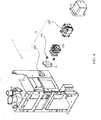
- FIG. 1 is a schematic structural diagram of a ventilation apparatus 1 provided by an embodiment of the disclosure.
- FIG. 2 is a simplified diagram of an interior of the ventilation apparatus 1 provided by an embodiment of the disclosure.
- FIG. 3 is an exploded view, in one direction, of the ventilation apparatus 1 provided by an embodiment of the disclosure.
- the ventilation apparatus 1 provided by an embodiment of the disclosure comprises a housing 11, an inhalation branch 16, a control unit 17, a gas source port 18, an exhalation branch 19, and a paramagnetic oxygen sensor 12.
- the paramagnetic oxygen sensor 12 is configured to detect oxygen content in the inhalation branch 16, and the paramagnetic oxygen sensor 12 is basically free of loss during measurement, so that the service life may be prolonged, the condition of inaccurate detection precision caused by untimely replacement after long-term use is avoided, the safety of the ventilation apparatus 1 during use is ensured, and the risk to a patient is avoided.
- the gas source port 18 is provided on the housing 11, the inhalation branch 16, the control unit 17 and the exhalation branch 19 are enclosed within the housing 11, the paramagnetic oxygen sensor 12 is provided outside the housing 11 by means of a mounting assembly, for example, a screw, a snap-fit fastener, etc., and an operator may maintain the paramagnetic oxygen sensor 12 without dismounting the housing 11, thereby facilitating maintenance of the paramagnetic oxygen sensor 12.
- the ventilation apparatus 1 provided by the embodiment of the disclosure may be a ventilator, an anaesthesia machine, etc.
- the gas source port 18 in the embodiment of the disclosure is in communication with the inhalation branch 16, and the inhalation branch 16 and the exhalation branch 19 are connected to a mouth and a nose of the patient by means of a patient pipeline.
- gas introduced from the gas source port 18 is transmitted to the mouth and the nose of the patient by means of the inhalation branch 16.
- exhaled gas is exhausted by means of the exhalation branch 19.
- the control unit 17 may control opening and closing of the inhalation branch 16 and the exhalation branch 19 separately, thereby achieving normal use of the ventilation apparatus 1.
- An outside the housing 11 referred to in the embodiment of the disclosure refers to a spatial area between the housing and an area outside the interior where the inhalation branch 16 is provided.
- the housing 11 provided in the embodiment of the disclosure comprises a body 112 and a mounting groove 113, and the paramagnetic oxygen sensor 12 is provided in the mounting groove 113, which may effectively reduce an overall size of the ventilation apparatus 1.
- the ventilation apparatus 1 provided by the embodiment of the disclosure further comprises a mounting door 20, the mounting door 20 covers an opening position of the mounting groove 113, one side of the mounting door 20 is hinged to the body 112, a hook 181 is provided on the other side of the mounting door 20, a hanging groove 182 is provided in the body 112, and when the hook 181 is hung in the hanging groove 182, the mounting door 20 and the body 112 may be locked, so that the effect of shielding the paramagnetic oxygen sensor 12 is achieved, and an appearance of the ventilation apparatus 1 may be more attractive.
- a first electromagnetic assembly 183 is provided on the hook 181, a second electromagnetic assembly 184 is provided in the hanging groove 182, the first electromagnetic assembly 183 and the second electromagnetic assembly 184 are connected to a power source separately, and when at least one of the first electromagnetic assembly 183 and the second electromagnetic assembly 184 is energized, attraction of the first electromagnetic assembly 183 and the second electromagnetic assembly 184 may be achieved, thereby further improving secure locking between the mounting door 20 and the body 112.
- the paramagnetic oxygen sensor 12 needs to be maintained or inspected, only the mounting door 20 needs to be opened, which is simple and convenient.
- latches, screws and other locking structures may also be provided between the mounting door 20 and the body 112 of the housing 11 to lock the mounting door 20 to the body 112 after the mounting door is closed.
- the housing 11, referring to a housing part that needs to be dismounted by service personnel with a tool, of the ventilation apparatus is referred to as "housing".
- the mounting door 20 may also be replaced with other shielding structures to match the housing 11 to jointly accommodate the paramagnetic oxygen sensor 12.
- the body 112 is provided with the mounting groove 113, and the paramagnetic oxygen sensor 12 is entirely or partially accommodated in the mounting groove 113.
- the paramagnetic oxygen sensor 12 is provided on an outer surface of the body 112, and no mounting door 20 is additionally provided, thereby facilitating mounting of the paramagnetic oxygen sensor 12; and it is also possible that the paramagnetic oxygen sensor 12 is directly mounted outside the housing 11 by means of the mounting assembly, and no mounting groove 113 and no mounting door 20 are provided.
- the mounting door 20 and the body 112 may also be locked by means of other easily-removable locking structures, for example, hook structures, etc., all of which fall within the scope of protection of the application.
- FIG. 4 is an exploded view, in another direction, of the ventilation apparatus 1 provided by an embodiment of the disclosure.
- the ventilation apparatus 1 provided by the embodiment of the disclosure further comprises a buffer structure 13, a mounting error prevention structure and an outer cover 15.
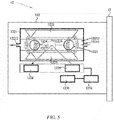
- FIG. 5 is a simplified diagram of a structure of the paramagnetic oxygen sensor 12 provided by an embodiment of the disclosure.
- the paramagnetic oxygen sensor 12 provided by the embodiment of the disclosure comprises a paramagnetic oxygen sensor body 122, wherein the paramagnetic oxygen sensor body 122 comprises a housing 1221, a first magnetic pole 1222, a second magnetic pole 1223, a first hollow sphere 1224, a second hollow sphere 1225, a metal band 1226, a planar mirror 1227, a photocell 1228, a light source assembly 1229, a controller 1230, and an amplifier 1231.
- a gas inlet 12211, a gas outlet 12212 and a gas channel 12213 are provided in the housing 1221, the gas inlet 12211 and the gas outlet 12212 are located at two ends of the gas channel 12213 respectively, gradients of magnetic field intensities of the first magnetic pole 1222 and the second magnetic pole 1223 are opposite, and the first magnetic pole and the second magnetic pole are provided in the housing 1221.
- the metal band 1226 is provided on the housing 1221, the first hollow sphere 1224 and the second hollow sphere 1225 which are equal in volume are provided in the gas channel 12213 by means of the metal band 1226, the first hollow sphere 1224 and the second hollow sphere 1225 are provided in a gap between the first magnetic pole 1222 and the second magnetic pole 1223, and the first hollow sphere 1224 and the second hollow sphere 1225 rotate with the metal band 1226 as an axis of rotation but may not swing vertically.
- the planar mirror 1227 is provided at an intersection point of a connecting line of the first hollow sphere 1224 and the second hollow sphere 1225 and the metal band 1226, the controller 1230 enables the light source assembly 1229 to emit a light ray by means of the amplifier 1231, and the emitted light ray irradiates the mirror 1227 and then is reflected to the photocell 1228.
- the controller 1230 enables the light source assembly 1229 to emit a light ray by means of the amplifier 1231, and the emitted light ray irradiates the mirror 1227 and then is reflected to the photocell 1228.
- a molecular density of an area close to the magnetic field intensity is relatively high, and a pressure difference in direct proportion to the oxygen content is generated in a gradient direction of the magnetic field intensity, such that the first hollow sphere 1224 and the second hollow sphere 1225 generate a thrust due to the pressure difference, and the thrust makes the first hollow sphere 1224 and the second hollow sphere 1225 deflect at an angle.
- the planar mirror 1227 also deflects, thereby making irradiation received by the photocell 1228 change, and then an electric signal is generated, wherein the electric signal is in direct proportion to the deflection angle of the first hollow sphere 1224 and the second hollow sphere 1225 and is in direct proportion to the oxygen content in the measured gas.
- the paramagnetic oxygen sensor 12 uses physical characteristics of oxygen, and the paramagnetic oxygen sensor 12 is basically free of loss during measurement, so the paramagnetic oxygen sensor 12 is long in service life and may be free of replacement in an entire life cycle of the ventilation apparatus 1, the problem of inaccurate precision after long-term use of a chemistry oxygen battery is avoided, and the safety and reliability of the ventilation apparatus 1 are improved.
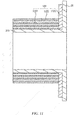
- FIG. 6 is a cutaway view of the ventilation apparatus 1 provided by an embodiment of the disclosure
- FIG. 7 is a partially enlarged diagram of portion A in FIG. 6 . As shown in FIGS.
- At least part of the buffer structure 13 is provided outside the paramagnetic oxygen sensor 12, so that vibration transmitted into the paramagnetic oxygen sensor 12 may be effectively reduced, damage to the internal structure of the paramagnetic oxygen sensor 12 is avoided, and the accuracy of measuring the oxygen concentration by the paramagnetic oxygen sensor 12 is ensured.
- the buffer structure 13 comprises a buffer connecting member 131, and the paramagnetic oxygen sensor 12 is connected to the housing 11 by means of the buffer connecting member 131 to guarantee that the paramagnetic oxygen sensor 12 may move relative to the housing 11.
- the paramagnetic oxygen sensor 12 is not completely fastened to the housing 11, so a certain shaking amount exists between the paramagnetic oxygen sensor 12 and the housing 11, vibration directly transmitted to the paramagnetic oxygen sensor 12 may be reduced, and the damage to the internal structure of the paramagnetic oxygen sensor 12 is avoided.
- FIG. 8 is a schematic structural diagram of the buffer connecting member 131 provided by an embodiment of the disclosure, and the buffer connecting member 131 comprises a connector 1312, a sliding portion 1311, and a threaded portion 1313 connected in sequence.
- the ventilation apparatus 1 provided by the embodiment of the disclosure further comprises a paramagnetic oxygen adapter block 21, wherein the paramagnetic oxygen adapter block 21 movably sleeves the sliding portion 1311, and the buffer connecting member 131 is fixed to the housing 11 by means of the threaded portion 1313.
- a thickness of the paramagnetic oxygen adapter block 21 is smaller than a distance between the connector 1312 and the housing 11, so as to guarantee that the paramagnetic oxygen adapter block 21 is limited to movement between the connector 1312 and the housing 11.
- a connecting hole is provided in the paramagnetic oxygen adapter block 21, the buffer connecting member 131 penetrates the connecting hole, and a diameter of the connecting hole is larger than that of the sliding portion 1311, so as to guarantee that the paramagnetic oxygen adapter block 21 may move in a radial direction relative to the buffer connecting member 131, and the paramagnetic oxygen adapter block 21 moves relative to the housing 11 in the radial direction of the buffer connecting member 131.
- the buffer connecting member 131 and the housing 11 may also be fixed by welding or other modes.
- two buffer connecting members 131 are provided, distances between axes of the two buffer connecting members 131 located at different mounting positions and a center line of the mounting hole 111 are different, and when the paramagnetic oxygen adapter block 21 is mounted, a good mounting error prevention effect may be achieved, thereby guaranteeing that a mounting direction of the paramagnetic oxygen sensor 12 is correct, and achieving normal use of the paramagnetic oxygen sensor 12.
- three, four or more buffer connecting members 131 may also be provided.
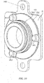
- FIG. 9 is a schematic structural diagram of the paramagnetic oxygen adapter block 21 provided by an embodiment of the disclosure
- FIG. 10 is a schematic structural diagram of the paramagnetic oxygen adapter block 21 and a buffer pad 132 provided by an embodiment of the disclosure.
- the buffer pad 132 comprises a first buffer portion 1321 and a second buffer portion 1322 connected to each other, wherein the first buffer portion 1321 is provided between the housing 11 and the paramagnetic oxygen sensor 12.
- the first buffer portion 1321 may absorb vibration generated by movement of the paramagnetic oxygen sensor 12 relative to the housing 11 in a horizontal direction of FIG. 6 ; and on the other hand, the first buffer portion 1321 may absorb vibration generated from the housing 11.
- the first buffer portion 1321 may be made of an elastic deformable material such as rubber, and when the paramagnetic oxygen adapter block 21 moves relative to the housing 11, constant sealing between the housing 11 and the paramagnetic oxygen sensor 12 may be achieved.
- the second buffer portion 1322 is provided between the inhalation branch 16 and the paramagnetic oxygen sensor 12; on one hand, the second buffer portion 1322 may absorb vibration generated by movement of the paramagnetic oxygen sensor 12 relative to the inhalation branch 16 in a vertical direction of FIG. 6 ; and on the other hand, the second buffer portion 1322 may achieve constant sealing between the paramagnetic oxygen sensor 12 and the inhalation branch 16, prevent gas leakage, and improve a utilization rate of the ventilation apparatus 1.
- first buffer portion 1321 or the second buffer portion 1322, which may also achieve buffer and sealing effects.
- the paramagnetic oxygen adapter block 21 provided by the embodiment of the disclosure comprises an adapter tube 211, and as shown in FIG. 4 , the adapter tube 211 may extend into the mounting hole 111 in the housing 11, and the adapter tube 211 is connected to the inhalation branch 16 provided in the housing 11, thereby achieving the effect of transmitting the gas in the ventilation apparatus 1 into the paramagnetic oxygen sensor 12.
- the ventilation apparatus 1 further comprises the mounting assembly
- the paramagnetic oxygen sensor 12 may be mounted on the housing 11 by means of the mounting assembly
- the mounting assembly in the embodiment of the disclosure may comprise a plate body of the paramagnetic oxygen adapter block 21 and the buffer connecting member 131, wherein the plate body of the paramagnetic oxygen adapter block 21, the buffer connecting member 131 and the adapter tube 211 may be integrated.
- a gas inlet of the paramagnetic oxygen sensor 12 may also be connected to the inhalation branch 16 by means of a flexible-textured sampling tube, thereby achieving the effect of transmitting the gas of the internal inhalation branch 16 of the ventilation apparatus 1 into the paramagnetic oxygen sensor 12.
- the mounting hole 111 the paramagnetic oxygen adapter block 21 and the housing 11 may be well positioned and mounted, thereby improving the mounting efficiency and precision of the paramagnetic oxygen sensor 12.
- the adapter tube 211 provided by the embodiment of the disclosure extends into the inhalation branch 16, the second buffer portion 1322 sleeves a periphery of the adapter tube 211, and the periphery of the adapter tube 211 abuts against an inner peripheral wall of the inhalation branch 16, thereby achieving sealing between the adapter tube 211 and the inhalation branch 16.
- the mounting groove 2111 is provided in the periphery of the adapter tube 211 provided by the embodiment of the disclosure, and the second buffer portion 1322 is provided in the mounting groove 2111, so that the second buffer portion 1322 may be well mounted and positioned, and the second buffer portion 1322 is prevented from deviating during the use of the ventilation apparatus 1.
- the first buffer portion 1321 and the second buffer portion 1322 may be integrally formed, thereby simplifying an assembly process of the first buffer portion 1321 and the second buffer potion 1322 to the paramagnetic oxygen adapter block 21, and improving the mounting efficiency of the ventilation apparatus 1.
- the first buffer portion 1321, the second buffer portion 1322 and the paramagnetic oxygen adapter block 21 may also be integrally formed, which improves the mounting efficiency of the ventilation apparatus 1.
- FIG. 11 is a schematic structural diagram of another paramagnetic oxygen adapter block 21 and another buffer pad 132 provided by other embodiments, and as shown in FIG. 11 , a plurality of through holes 1323 may also be provided in the second buffer portion 1322, which may also improve the compressibility of the second buffer portion 1322.
- the through hole 1323 extends in a lengthwise direction of the adapter tube 211, which may improve a deformation effect of the second buffer portion 1322 in a vertical direction in FIG. 11 .
- the ventilation apparatus 1 provided by the embodiment of the disclosure further comprises a mounting error prevention structure
- the mounting error prevention structure may correctly mount the paramagnetic oxygen sensor 12 on the housing 11 in a preset direction, thereby guaranteeing the normal use of the paramagnetic oxygen sensor 12.
- the mounting error prevention structure comprises three first positioning sets 141 and two second positioning sets 142.
- the first positioning set 141 comprises a first positioning column 1411 and a first positioning hole 1412, the first positioning column 1411 being provided on the buffer pad 132, and the first positioning hole 1412 being provided on the housing 11; and the second positioning set 142 comprises a second positioning hole 1421 and a third positioning hole 1422, the second positioning hole 1421 and the third positioning hole 1422 being in one-to-one correspondence, the second positioning hole 1421 being provided on the paramagnetic oxygen adapter block 21, and the third positioning hole 1422 being provided on the housing 11.
- the first positioning column 1411 When the first positioning column 1411 is inserted into the corresponding first positioning hole 1412, the second positioning hole 1421 is aligned with the corresponding third positioning hole 1422, and the buffer connecting member 131 sequentially penetrates the second positioning hole 1421 and the corresponding third positioning hole 1422 to connect the paramagnetic oxygen sensor 12 to the housing 11.
- the paramagnetic oxygen sensor 12 By means of cooperation between the first positioning set 141 and the second positioning set 142, the paramagnetic oxygen sensor 12 is mounted on the housing 11 in the preset direction.
- the first positioning column 1411 may also be provided on the paramagnetic oxygen sensor 12, or on both the paramagnetic oxygen sensor 12 and the buffer pad 132.
- one, two or more first positioning sets 141 may also be provided, and one, three or more second positioning sets may also be provided.
- the positions of the first positioning column 1411 and the first positioning hole 1412 may be interchanged, and the positions of the second positioning hole 1421 and the third positioning hole 1422 may be interchanged.
- a mounting error prevention effect may also be achieved by means of a shape fit.
- three first positioning sets 141 may be provided, shapes of the first positioning column 1411 and the first positioning hole 1412 of one of the first positioning sets 141 are different from those of the other two positioning sets, so as to achieve the mounting error prevention effect.
- FIG. 12 is a schematic structural diagram of the outer cover 15 provided by an embodiment of the disclosure.
- the paramagnetic oxygen sensor 12 is provided in the outer cover 15, and the outer cover 15 is fixed to the housing 11, thereby achieving the effect of protecting the paramagnetic oxygen sensor 12, preventing external dust from entering the paramagnetic oxygen sensor 12, and guaranteeing normal use of the paramagnetic oxygen sensor 12.
- the outer cover 15 may be made of metal and may also play a role in shielding the paramagnetic oxygen sensor 12, thereby guaranteeing that the paramagnetic oxygen sensor 12 is free of interference from external signals when working.
- FIG. 13 is a schematic structural diagram of the buffer cover 133 provided by an embodiment of the disclosure, and as shown in FIGS. 7 and 13 , the buffer cover 133 sleeves a part of the periphery of the paramagnetic oxygen sensor 12 and abuts against the outer cover 15.
- the outer cover 15 is fixedly connected to the housing 11, and vibration of the housing 11 is absorbed by the buffer cover 133 by means of the outer cover 15, thereby further reducing vibration borne by the paramagnetic oxygen sensor 12, and avoiding damage to the internal structure of the paramagnetic oxygen sensor 12.
- peripheral surfaces of the paramagnetic oxygen sensor 12 are completely covered by the buffer cover 133, so that the effect of better reducing the vibration borne by the paramagnetic oxygen sensor 12 may be achieved.
- a plurality of protrusions 1331 are provided on a periphery of the buffer cover 133, such that the buffer cover 133 and the outer cover 15 abut against each other more closely, thereby avoiding relative movement between the buffer cover 133 and the outer cover 15, and improving capacity to absorb vibration by the buffer cover 133.
- the outer cover 15 and the buffer cover 133 may be integrally formed of rubber, thereby reducing assembly steps of the ventilation apparatus 1 and improving the mounting efficiency of the ventilation apparatus 1.
- the buffer cover 133 covers at least one surface of the paramagnetic oxygen sensor 12, and the buffer cover 133 is connected to the housing 11, such that the buffer cover 133 may absorb part of vibration transmitted from the housing 11 and may also achieve the effect of avoiding damage to the internal structure of the paramagnetic oxygen sensor 12.
Landscapes
- Health & Medical Sciences (AREA)
- Life Sciences & Earth Sciences (AREA)
- Engineering & Computer Science (AREA)
- General Health & Medical Sciences (AREA)
- Heart & Thoracic Surgery (AREA)
- Biomedical Technology (AREA)
- Pulmonology (AREA)
- Animal Behavior & Ethology (AREA)
- Public Health (AREA)
- Veterinary Medicine (AREA)
- Emergency Medicine (AREA)
- Anesthesiology (AREA)
- Hematology (AREA)
- Physics & Mathematics (AREA)
- Pathology (AREA)
- Chemical & Material Sciences (AREA)
- Biophysics (AREA)
- Medical Informatics (AREA)
- Molecular Biology (AREA)
- Surgery (AREA)
- Physiology (AREA)
- Combustion & Propulsion (AREA)
- Obesity (AREA)
- Food Science & Technology (AREA)
- Medicinal Chemistry (AREA)
- Analytical Chemistry (AREA)
- Biochemistry (AREA)
- General Physics & Mathematics (AREA)
- Immunology (AREA)
- Sampling And Sample Adjustment (AREA)
Applications Claiming Priority (1)
| Application Number | Priority Date | Filing Date | Title |
|---|---|---|---|
| PCT/CN2018/101162 WO2020034216A1 (zh) | 2018-08-17 | 2018-08-17 | 一种通气设备 |
Publications (3)
| Publication Number | Publication Date |
|---|---|
| EP3838320A1 true EP3838320A1 (de) | 2021-06-23 |
| EP3838320A4 EP3838320A4 (de) | 2021-08-25 |
| EP3838320B1 EP3838320B1 (de) | 2024-07-31 |
Family
ID=69524570
Family Applications (1)
| Application Number | Title | Priority Date | Filing Date |
|---|---|---|---|
| EP18930080.9A Active EP3838320B1 (de) | 2018-08-17 | 2018-08-17 | Belüftungsvorrichtung |
Country Status (4)
| Country | Link |
|---|---|
| US (1) | US12090277B2 (de) |
| EP (1) | EP3838320B1 (de) |
| CN (2) | CN112203707B (de) |
| WO (1) | WO2020034216A1 (de) |
Families Citing this family (2)
| Publication number | Priority date | Publication date | Assignee | Title |
|---|---|---|---|---|
| CN112964773A (zh) * | 2021-03-10 | 2021-06-15 | 西人马联合测控(泉州)科技有限公司 | 氧传感器和提高氧传感器稳定性的方法 |
| CN118465185B (zh) * | 2024-05-09 | 2025-06-06 | 武汉中新汽车零部件有限公司 | 一种碳罐排放管排气量检测设备 |
Family Cites Families (19)
| Publication number | Priority date | Publication date | Assignee | Title |
|---|---|---|---|---|
| EP1237614B1 (de) * | 1999-12-10 | 2005-10-19 | Vapotherm, Inc. | Vorrichtung zur atemwegstherapie |
| JP4440439B2 (ja) * | 2000-06-27 | 2010-03-24 | 株式会社メトラン | 人工呼吸装置およびそのモニタ装置 |
| US6581595B1 (en) * | 2000-11-14 | 2003-06-24 | Sensormedics Corporation | Positive airway pressure device with indirect calorimetry system |
| US6613280B2 (en) * | 2001-03-20 | 2003-09-02 | Therox, Inc. | Disposable cartridge for producing gas-enriched fluids |
| AU2003215788A1 (en) * | 2002-03-22 | 2003-10-08 | Instrumentarium Corporation | Paramagnetic oxygen sensing apparatus and method |
| EP1775582A1 (de) * | 2005-10-14 | 2007-04-18 | General Electric Company | Paramagnetischer Gas-Analysator mit Sensorbefestigung |
| JP4863960B2 (ja) * | 2007-10-12 | 2012-01-25 | 日立オートモティブシステムズ株式会社 | 酸素センサの検査方法 |
| US8042402B2 (en) * | 2008-05-01 | 2011-10-25 | General Electric Company | Modular sensor assembly |
| EP2123320A1 (de) * | 2008-05-20 | 2009-11-25 | General Electric Company | Anordnung und Verfahren zur Überwachung eines medizinischen Monitors |
| EP2340073B1 (de) * | 2008-10-17 | 2016-09-21 | Koninklijke Philips N.V. | Portierungsblock für ein medizinisches beatmungsgerät |
| DE102009013396B3 (de) * | 2009-03-16 | 2010-08-05 | Dräger Medical AG & Co. KG | Vorrichtung und Verfahren zur Steuerung der Sauerstoffdosierung eines Beatmungsgerätes |
| EP2515105B1 (de) * | 2011-04-21 | 2019-01-02 | General Electric Company | Gassensor zum Messen einer paramagnetischen Gaskomponente |
| CN103908722A (zh) * | 2012-12-29 | 2014-07-09 | 北京谊安医疗系统股份有限公司 | 一种呼吸机氧浓度的监测与控制方法 |
| CN204106778U (zh) * | 2014-08-08 | 2015-01-21 | 北京谊安医疗系统股份有限公司 | 一种流量传感器安装结构 |
| CN105628075B (zh) * | 2014-11-06 | 2019-11-15 | 深圳迈瑞生物医疗电子股份有限公司 | 一种传感器安装座结构、氧浓度传感装置及呼吸设备 |
| DE102014017619B4 (de) * | 2014-11-28 | 2023-03-23 | Drägerwerk AG & Co. KGaA | Sensormodul für atembare Gasgemische, Beatmungsgerät, Therapiegerät und Verfahren zur Messung mehrerer Gase eines atembaren Gasgemisches |
| WO2016140980A1 (en) * | 2015-03-02 | 2016-09-09 | Covidien Lp | Medical ventilator, method for replacing an oxygen sensor on a medical ventilator, and medical ventilator assembly |
| CN106345021B (zh) * | 2015-07-23 | 2019-04-16 | 北京谊安医疗系统股份有限公司 | 一种用于呼吸机的流量传感器的连接件 |
| CN108348715B (zh) * | 2015-11-13 | 2021-03-19 | 欧根·卡根 | 呼吸机 |
-
2018
- 2018-08-17 EP EP18930080.9A patent/EP3838320B1/de active Active
- 2018-08-17 CN CN201880093627.2A patent/CN112203707B/zh active Active
- 2018-08-17 WO PCT/CN2018/101162 patent/WO2020034216A1/zh not_active Ceased
- 2018-08-17 CN CN202311580879.7A patent/CN117694870A/zh active Pending
-
2021
- 2021-02-07 US US17/169,526 patent/US12090277B2/en active Active
Also Published As
| Publication number | Publication date |
|---|---|
| WO2020034216A1 (zh) | 2020-02-20 |
| CN112203707B (zh) | 2023-12-12 |
| EP3838320A4 (de) | 2021-08-25 |
| US20210154428A1 (en) | 2021-05-27 |
| US12090277B2 (en) | 2024-09-17 |
| CN117694870A (zh) | 2024-03-15 |
| CN112203707A (zh) | 2021-01-08 |
| EP3838320B1 (de) | 2024-07-31 |
Similar Documents
| Publication | Publication Date | Title |
|---|---|---|
| US12090277B2 (en) | Ventilation apparatus | |
| US8621914B2 (en) | Respirator test accessory | |
| WO2006122092A3 (en) | Patient interface with respiratory gas measurement component | |
| EP2275031A1 (de) | Atemwegsadapter für die Leitung der ausgeatmeten Gase in einen Analysator | |
| CN103372256A (zh) | 呼出膜片阀 | |
| US20160331271A1 (en) | A manual resuscitator and capnograph assembly | |
| CN208568576U (zh) | 一种多组份气体吸收池 | |
| EP1420691B1 (de) | Vorrichtung zur quantitativen analyse von atemgasen | |
| EP1420842B1 (de) | Vorrichtung zur quantitativen analyse von atemgasen | |
| CN219982871U (zh) | 气体浓度和呼吸力学参数融合的测量装置及适配器 | |
| CN218512391U (zh) | 微量环氧乙烷检测装置 | |
| EP1420692A1 (de) | Vorrichtung für die quantitative analyse von atemgasen, umfassend einen passiven atemgasbefeuchter, in dem lichtstrahlen durch einen befeuchteten gasfluss geleitet werden | |
| CN210571944U (zh) | 二氧化碳红外线气体分析仪 | |
| CN217385192U (zh) | 一种医用二氧化碳传感器 | |
| CN223581752U (zh) | 耐高温的气体检测装置 | |
| CN223112123U (zh) | 氧电池安装座 | |
| KR102498414B1 (ko) | 고압 산소 챔버의 안전 개폐 방법 | |
| CN219302405U (zh) | 一种大气一氧化碳自动在线监测仪 | |
| CN116831556B (zh) | 气体浓度和呼吸力学参数融合的测量装置和方法及适配器 | |
| CN219830796U (zh) | 防爆型激光分析仪 | |
| CN219830730U (zh) | 粉尘浓度测定装置 | |
| CN221557195U (zh) | 一种呼吸机的气源模块及呼吸机 | |
| CN121977755A (en) | Respiratory protection equipment suitability checking system and method | |
| CN209525333U (zh) | 一种带有报警功能的气体检测装置 | |
| CN223861133U (zh) | 通气治疗设备的底盘结构及通气治疗设备 |
Legal Events
| Date | Code | Title | Description |
|---|---|---|---|
| STAA | Information on the status of an ep patent application or granted ep patent |
Free format text: STATUS: THE INTERNATIONAL PUBLICATION HAS BEEN MADE |
|
| PUAI | Public reference made under article 153(3) epc to a published international application that has entered the european phase |
Free format text: ORIGINAL CODE: 0009012 |
|
| STAA | Information on the status of an ep patent application or granted ep patent |
Free format text: STATUS: REQUEST FOR EXAMINATION WAS MADE |
|
| 17P | Request for examination filed |
Effective date: 20210301 |
|
| AK | Designated contracting states |
Kind code of ref document: A1 Designated state(s): AL AT BE BG CH CY CZ DE DK EE ES FI FR GB GR HR HU IE IS IT LI LT LU LV MC MK MT NL NO PL PT RO RS SE SI SK SM TR |
|
| A4 | Supplementary search report drawn up and despatched |
Effective date: 20210727 |
|
| RIC1 | Information provided on ipc code assigned before grant |
Ipc: A61M 16/00 20060101AFI20210721BHEP Ipc: G01N 27/74 20060101ALI20210721BHEP Ipc: G01R 33/16 20060101ALI20210721BHEP Ipc: A61B 5/083 20060101ALI20210721BHEP Ipc: A61B 5/087 20060101ALI20210721BHEP Ipc: A61B 5/097 20060101ALI20210721BHEP Ipc: A61M 16/10 20060101ALN20210721BHEP Ipc: G01N 33/497 20060101ALN20210721BHEP Ipc: A61B 5/08 20060101ALN20210721BHEP |
|
| DAV | Request for validation of the european patent (deleted) | ||
| DAX | Request for extension of the european patent (deleted) | ||
| GRAP | Despatch of communication of intention to grant a patent |
Free format text: ORIGINAL CODE: EPIDOSNIGR1 |
|
| STAA | Information on the status of an ep patent application or granted ep patent |
Free format text: STATUS: GRANT OF PATENT IS INTENDED |
|
| INTG | Intention to grant announced |
Effective date: 20230519 |
|
| RIC1 | Information provided on ipc code assigned before grant |
Ipc: A61B 5/08 20060101ALN20230509BHEP Ipc: G01N 33/497 20060101ALN20230509BHEP Ipc: A61M 16/10 20060101ALN20230509BHEP Ipc: G01N 33/00 20060101ALI20230509BHEP Ipc: A61B 5/097 20060101ALI20230509BHEP Ipc: A61B 5/087 20060101ALI20230509BHEP Ipc: A61B 5/083 20060101ALI20230509BHEP Ipc: G01R 33/16 20060101ALI20230509BHEP Ipc: G01N 27/74 20060101ALI20230509BHEP Ipc: A61M 16/00 20060101AFI20230509BHEP |
|
| GRAJ | Information related to disapproval of communication of intention to grant by the applicant or resumption of examination proceedings by the epo deleted |
Free format text: ORIGINAL CODE: EPIDOSDIGR1 |
|
| STAA | Information on the status of an ep patent application or granted ep patent |
Free format text: STATUS: REQUEST FOR EXAMINATION WAS MADE |
|
| STAA | Information on the status of an ep patent application or granted ep patent |
Free format text: STATUS: EXAMINATION IS IN PROGRESS |
|
| INTC | Intention to grant announced (deleted) | ||
| 17Q | First examination report despatched |
Effective date: 20231012 |
|
| GRAP | Despatch of communication of intention to grant a patent |
Free format text: ORIGINAL CODE: EPIDOSNIGR1 |
|
| STAA | Information on the status of an ep patent application or granted ep patent |
Free format text: STATUS: GRANT OF PATENT IS INTENDED |
|
| RIC1 | Information provided on ipc code assigned before grant |
Ipc: A61B 5/08 20060101ALN20240129BHEP Ipc: G01N 33/497 20060101ALN20240129BHEP Ipc: A61M 16/10 20060101ALN20240129BHEP Ipc: G01N 33/00 20060101ALI20240129BHEP Ipc: A61B 5/097 20060101ALI20240129BHEP Ipc: A61B 5/087 20060101ALI20240129BHEP Ipc: A61B 5/083 20060101ALI20240129BHEP Ipc: G01R 33/16 20060101ALI20240129BHEP Ipc: G01N 27/74 20060101ALI20240129BHEP Ipc: A61M 16/00 20060101AFI20240129BHEP |
|
| INTG | Intention to grant announced |
Effective date: 20240222 |
|
| GRAS | Grant fee paid |
Free format text: ORIGINAL CODE: EPIDOSNIGR3 |
|
| GRAA | (expected) grant |
Free format text: ORIGINAL CODE: 0009210 |
|
| STAA | Information on the status of an ep patent application or granted ep patent |
Free format text: STATUS: THE PATENT HAS BEEN GRANTED |
|
| AK | Designated contracting states |
Kind code of ref document: B1 Designated state(s): AL AT BE BG CH CY CZ DE DK EE ES FI FR GB GR HR HU IE IS IT LI LT LU LV MC MK MT NL NO PL PT RO RS SE SI SK SM TR |
|
| P01 | Opt-out of the competence of the unified patent court (upc) registered |
Free format text: CASE NUMBER: APP_35738/2024 Effective date: 20240626 |
|
| REG | Reference to a national code |
Ref country code: CH Ref legal event code: EP Ref country code: GB Ref legal event code: FG4D |
|
| REG | Reference to a national code |
Ref country code: DE Ref legal event code: R096 Ref document number: 602018072617 Country of ref document: DE |
|
| REG | Reference to a national code |
Ref country code: IE Ref legal event code: FG4D |
|
| REG | Reference to a national code |
Ref country code: SE Ref legal event code: TRGR |
|
| REG | Reference to a national code |
Ref country code: LT Ref legal event code: MG9D |
|
| REG | Reference to a national code |
Ref country code: NL Ref legal event code: MP Effective date: 20240731 |
|
| PG25 | Lapsed in a contracting state [announced via postgrant information from national office to epo] |
Ref country code: PT Free format text: LAPSE BECAUSE OF FAILURE TO SUBMIT A TRANSLATION OF THE DESCRIPTION OR TO PAY THE FEE WITHIN THE PRESCRIBED TIME-LIMIT Effective date: 20241202 |
|
| REG | Reference to a national code |
Ref country code: AT Ref legal event code: MK05 Ref document number: 1707894 Country of ref document: AT Kind code of ref document: T Effective date: 20240731 |
|
| PG25 | Lapsed in a contracting state [announced via postgrant information from national office to epo] |
Ref country code: PT Free format text: LAPSE BECAUSE OF FAILURE TO SUBMIT A TRANSLATION OF THE DESCRIPTION OR TO PAY THE FEE WITHIN THE PRESCRIBED TIME-LIMIT Effective date: 20241202 |
|
| PG25 | Lapsed in a contracting state [announced via postgrant information from national office to epo] |
Ref country code: NO Free format text: LAPSE BECAUSE OF FAILURE TO SUBMIT A TRANSLATION OF THE DESCRIPTION OR TO PAY THE FEE WITHIN THE PRESCRIBED TIME-LIMIT Effective date: 20241031 |
|
| PG25 | Lapsed in a contracting state [announced via postgrant information from national office to epo] |
Ref country code: NL Free format text: LAPSE BECAUSE OF FAILURE TO SUBMIT A TRANSLATION OF THE DESCRIPTION OR TO PAY THE FEE WITHIN THE PRESCRIBED TIME-LIMIT Effective date: 20240731 Ref country code: GR Free format text: LAPSE BECAUSE OF FAILURE TO SUBMIT A TRANSLATION OF THE DESCRIPTION OR TO PAY THE FEE WITHIN THE PRESCRIBED TIME-LIMIT Effective date: 20241101 Ref country code: FI Free format text: LAPSE BECAUSE OF FAILURE TO SUBMIT A TRANSLATION OF THE DESCRIPTION OR TO PAY THE FEE WITHIN THE PRESCRIBED TIME-LIMIT Effective date: 20240731 Ref country code: PL Free format text: LAPSE BECAUSE OF FAILURE TO SUBMIT A TRANSLATION OF THE DESCRIPTION OR TO PAY THE FEE WITHIN THE PRESCRIBED TIME-LIMIT Effective date: 20240731 |
|
| PG25 | Lapsed in a contracting state [announced via postgrant information from national office to epo] |
Ref country code: BG Free format text: LAPSE BECAUSE OF FAILURE TO SUBMIT A TRANSLATION OF THE DESCRIPTION OR TO PAY THE FEE WITHIN THE PRESCRIBED TIME-LIMIT Effective date: 20240731 |
|
| PG25 | Lapsed in a contracting state [announced via postgrant information from national office to epo] |
Ref country code: LV Free format text: LAPSE BECAUSE OF FAILURE TO SUBMIT A TRANSLATION OF THE DESCRIPTION OR TO PAY THE FEE WITHIN THE PRESCRIBED TIME-LIMIT Effective date: 20240731 |
|
| PG25 | Lapsed in a contracting state [announced via postgrant information from national office to epo] |
Ref country code: IS Free format text: LAPSE BECAUSE OF FAILURE TO SUBMIT A TRANSLATION OF THE DESCRIPTION OR TO PAY THE FEE WITHIN THE PRESCRIBED TIME-LIMIT Effective date: 20241130 Ref country code: AT Free format text: LAPSE BECAUSE OF FAILURE TO SUBMIT A TRANSLATION OF THE DESCRIPTION OR TO PAY THE FEE WITHIN THE PRESCRIBED TIME-LIMIT Effective date: 20240731 |
|
| PG25 | Lapsed in a contracting state [announced via postgrant information from national office to epo] |
Ref country code: HR Free format text: LAPSE BECAUSE OF FAILURE TO SUBMIT A TRANSLATION OF THE DESCRIPTION OR TO PAY THE FEE WITHIN THE PRESCRIBED TIME-LIMIT Effective date: 20240731 |
|
| PG25 | Lapsed in a contracting state [announced via postgrant information from national office to epo] |
Ref country code: ES Free format text: LAPSE BECAUSE OF FAILURE TO SUBMIT A TRANSLATION OF THE DESCRIPTION OR TO PAY THE FEE WITHIN THE PRESCRIBED TIME-LIMIT Effective date: 20240731 Ref country code: RS Free format text: LAPSE BECAUSE OF FAILURE TO SUBMIT A TRANSLATION OF THE DESCRIPTION OR TO PAY THE FEE WITHIN THE PRESCRIBED TIME-LIMIT Effective date: 20241031 |
|
| PG25 | Lapsed in a contracting state [announced via postgrant information from national office to epo] |
Ref country code: RS Free format text: LAPSE BECAUSE OF FAILURE TO SUBMIT A TRANSLATION OF THE DESCRIPTION OR TO PAY THE FEE WITHIN THE PRESCRIBED TIME-LIMIT Effective date: 20241031 Ref country code: PL Free format text: LAPSE BECAUSE OF FAILURE TO SUBMIT A TRANSLATION OF THE DESCRIPTION OR TO PAY THE FEE WITHIN THE PRESCRIBED TIME-LIMIT Effective date: 20240731 Ref country code: NO Free format text: LAPSE BECAUSE OF FAILURE TO SUBMIT A TRANSLATION OF THE DESCRIPTION OR TO PAY THE FEE WITHIN THE PRESCRIBED TIME-LIMIT Effective date: 20241031 Ref country code: NL Free format text: LAPSE BECAUSE OF FAILURE TO SUBMIT A TRANSLATION OF THE DESCRIPTION OR TO PAY THE FEE WITHIN THE PRESCRIBED TIME-LIMIT Effective date: 20240731 Ref country code: LV Free format text: LAPSE BECAUSE OF FAILURE TO SUBMIT A TRANSLATION OF THE DESCRIPTION OR TO PAY THE FEE WITHIN THE PRESCRIBED TIME-LIMIT Effective date: 20240731 Ref country code: IS Free format text: LAPSE BECAUSE OF FAILURE TO SUBMIT A TRANSLATION OF THE DESCRIPTION OR TO PAY THE FEE WITHIN THE PRESCRIBED TIME-LIMIT Effective date: 20241130 Ref country code: HR Free format text: LAPSE BECAUSE OF FAILURE TO SUBMIT A TRANSLATION OF THE DESCRIPTION OR TO PAY THE FEE WITHIN THE PRESCRIBED TIME-LIMIT Effective date: 20240731 Ref country code: GR Free format text: LAPSE BECAUSE OF FAILURE TO SUBMIT A TRANSLATION OF THE DESCRIPTION OR TO PAY THE FEE WITHIN THE PRESCRIBED TIME-LIMIT Effective date: 20241101 Ref country code: FI Free format text: LAPSE BECAUSE OF FAILURE TO SUBMIT A TRANSLATION OF THE DESCRIPTION OR TO PAY THE FEE WITHIN THE PRESCRIBED TIME-LIMIT Effective date: 20240731 Ref country code: ES Free format text: LAPSE BECAUSE OF FAILURE TO SUBMIT A TRANSLATION OF THE DESCRIPTION OR TO PAY THE FEE WITHIN THE PRESCRIBED TIME-LIMIT Effective date: 20240731 Ref country code: BG Free format text: LAPSE BECAUSE OF FAILURE TO SUBMIT A TRANSLATION OF THE DESCRIPTION OR TO PAY THE FEE WITHIN THE PRESCRIBED TIME-LIMIT Effective date: 20240731 Ref country code: AT Free format text: LAPSE BECAUSE OF FAILURE TO SUBMIT A TRANSLATION OF THE DESCRIPTION OR TO PAY THE FEE WITHIN THE PRESCRIBED TIME-LIMIT Effective date: 20240731 |
|
| PG25 | Lapsed in a contracting state [announced via postgrant information from national office to epo] |
Ref country code: SM Free format text: LAPSE BECAUSE OF FAILURE TO SUBMIT A TRANSLATION OF THE DESCRIPTION OR TO PAY THE FEE WITHIN THE PRESCRIBED TIME-LIMIT Effective date: 20240731 Ref country code: DK Free format text: LAPSE BECAUSE OF FAILURE TO SUBMIT A TRANSLATION OF THE DESCRIPTION OR TO PAY THE FEE WITHIN THE PRESCRIBED TIME-LIMIT Effective date: 20240731 Ref country code: RO Free format text: LAPSE BECAUSE OF FAILURE TO SUBMIT A TRANSLATION OF THE DESCRIPTION OR TO PAY THE FEE WITHIN THE PRESCRIBED TIME-LIMIT Effective date: 20240731 |
|
| PG25 | Lapsed in a contracting state [announced via postgrant information from national office to epo] |
Ref country code: LU Free format text: LAPSE BECAUSE OF NON-PAYMENT OF DUE FEES Effective date: 20240817 |
|
| PG25 | Lapsed in a contracting state [announced via postgrant information from national office to epo] |
Ref country code: MC Free format text: LAPSE BECAUSE OF FAILURE TO SUBMIT A TRANSLATION OF THE DESCRIPTION OR TO PAY THE FEE WITHIN THE PRESCRIBED TIME-LIMIT Effective date: 20240731 Ref country code: EE Free format text: LAPSE BECAUSE OF FAILURE TO SUBMIT A TRANSLATION OF THE DESCRIPTION OR TO PAY THE FEE WITHIN THE PRESCRIBED TIME-LIMIT Effective date: 20240731 |
|
| PG25 | Lapsed in a contracting state [announced via postgrant information from national office to epo] |
Ref country code: CZ Free format text: LAPSE BECAUSE OF FAILURE TO SUBMIT A TRANSLATION OF THE DESCRIPTION OR TO PAY THE FEE WITHIN THE PRESCRIBED TIME-LIMIT Effective date: 20240731 |
|
| PG25 | Lapsed in a contracting state [announced via postgrant information from national office to epo] |
Ref country code: SK Free format text: LAPSE BECAUSE OF FAILURE TO SUBMIT A TRANSLATION OF THE DESCRIPTION OR TO PAY THE FEE WITHIN THE PRESCRIBED TIME-LIMIT Effective date: 20240731 Ref country code: IT Free format text: LAPSE BECAUSE OF FAILURE TO SUBMIT A TRANSLATION OF THE DESCRIPTION OR TO PAY THE FEE WITHIN THE PRESCRIBED TIME-LIMIT Effective date: 20240731 |
|
| REG | Reference to a national code |
Ref country code: DE Ref legal event code: R097 Ref document number: 602018072617 Country of ref document: DE |
|
| PLBE | No opposition filed within time limit |
Free format text: ORIGINAL CODE: 0009261 |
|
| STAA | Information on the status of an ep patent application or granted ep patent |
Free format text: STATUS: NO OPPOSITION FILED WITHIN TIME LIMIT |
|
| GBPC | Gb: european patent ceased through non-payment of renewal fee |
Effective date: 20241031 |
|
| REG | Reference to a national code |
Ref country code: BE Ref legal event code: MM Effective date: 20240831 |
|
| 26N | No opposition filed |
Effective date: 20250501 |
|
| PG25 | Lapsed in a contracting state [announced via postgrant information from national office to epo] |
Ref country code: GB Free format text: LAPSE BECAUSE OF NON-PAYMENT OF DUE FEES Effective date: 20241031 |
|
| PG25 | Lapsed in a contracting state [announced via postgrant information from national office to epo] |
Ref country code: BE Free format text: LAPSE BECAUSE OF NON-PAYMENT OF DUE FEES Effective date: 20240831 |
|
| PG25 | Lapsed in a contracting state [announced via postgrant information from national office to epo] |
Ref country code: FR Free format text: LAPSE BECAUSE OF NON-PAYMENT OF DUE FEES Effective date: 20240930 |
|
| PG25 | Lapsed in a contracting state [announced via postgrant information from national office to epo] |
Ref country code: IE Free format text: LAPSE BECAUSE OF NON-PAYMENT OF DUE FEES Effective date: 20240817 |
|
| PGFP | Annual fee paid to national office [announced via postgrant information from national office to epo] |
Ref country code: DE Payment date: 20250820 Year of fee payment: 8 |
|
| PGFP | Annual fee paid to national office [announced via postgrant information from national office to epo] |
Ref country code: CH Payment date: 20250916 Year of fee payment: 8 Ref country code: SE Payment date: 20250820 Year of fee payment: 8 |
|
| PG25 | Lapsed in a contracting state [announced via postgrant information from national office to epo] |
Ref country code: CY Free format text: LAPSE BECAUSE OF FAILURE TO SUBMIT A TRANSLATION OF THE DESCRIPTION OR TO PAY THE FEE WITHIN THE PRESCRIBED TIME-LIMIT; INVALID AB INITIO Effective date: 20180817 |
|
| PG25 | Lapsed in a contracting state [announced via postgrant information from national office to epo] |
Ref country code: HU Free format text: LAPSE BECAUSE OF FAILURE TO SUBMIT A TRANSLATION OF THE DESCRIPTION OR TO PAY THE FEE WITHIN THE PRESCRIBED TIME-LIMIT; INVALID AB INITIO Effective date: 20180817 |