EP3838404A1 - Appareil pour introduire du gaz dans un réacteur - Google Patents
Appareil pour introduire du gaz dans un réacteur Download PDFInfo
- Publication number
- EP3838404A1 EP3838404A1 EP21156490.1A EP21156490A EP3838404A1 EP 3838404 A1 EP3838404 A1 EP 3838404A1 EP 21156490 A EP21156490 A EP 21156490A EP 3838404 A1 EP3838404 A1 EP 3838404A1
- Authority
- EP
- European Patent Office
- Prior art keywords
- conduit
- inlet
- outlet conduit
- velocity
- longitudinal axis
- Prior art date
- Legal status (The legal status is an assumption and is not a legal conclusion. Google has not performed a legal analysis and makes no representation as to the accuracy of the status listed.)
- Withdrawn
Links
Images









Classifications
-
- C—CHEMISTRY; METALLURGY
- C07—ORGANIC CHEMISTRY
- C07C—ACYCLIC OR CARBOCYCLIC COMPOUNDS
- C07C5/00—Preparation of hydrocarbons from hydrocarbons containing the same number of carbon atoms
- C07C5/32—Preparation of hydrocarbons from hydrocarbons containing the same number of carbon atoms by dehydrogenation with formation of free hydrogen
- C07C5/327—Formation of non-aromatic carbon-to-carbon double bonds only
- C07C5/333—Catalytic processes
-
- B—PERFORMING OPERATIONS; TRANSPORTING
- B01—PHYSICAL OR CHEMICAL PROCESSES OR APPARATUS IN GENERAL
- B01J—CHEMICAL OR PHYSICAL PROCESSES, e.g. CATALYSIS OR COLLOID CHEMISTRY; THEIR RELEVANT APPARATUS
- B01J19/00—Chemical, physical or physico-chemical processes in general; Their relevant apparatus
- B01J19/26—Nozzle-type reactors, i.e. the distribution of the initial reactants within the reactor is effected by their introduction or injection through nozzles
-
- B—PERFORMING OPERATIONS; TRANSPORTING
- B01—PHYSICAL OR CHEMICAL PROCESSES OR APPARATUS IN GENERAL
- B01J—CHEMICAL OR PHYSICAL PROCESSES, e.g. CATALYSIS OR COLLOID CHEMISTRY; THEIR RELEVANT APPARATUS
- B01J23/00—Catalysts comprising metals or metal oxides or hydroxides, not provided for in group B01J21/00
- B01J23/90—Regeneration or reactivation
- B01J23/94—Regeneration or reactivation of catalysts comprising metals, oxides or hydroxides of the iron group metals or copper
-
- B—PERFORMING OPERATIONS; TRANSPORTING
- B01—PHYSICAL OR CHEMICAL PROCESSES OR APPARATUS IN GENERAL
- B01J—CHEMICAL OR PHYSICAL PROCESSES, e.g. CATALYSIS OR COLLOID CHEMISTRY; THEIR RELEVANT APPARATUS
- B01J23/00—Catalysts comprising metals or metal oxides or hydroxides, not provided for in group B01J21/00
- B01J23/90—Regeneration or reactivation
- B01J23/96—Regeneration or reactivation of catalysts comprising metals, oxides or hydroxides of the noble metals
-
- B—PERFORMING OPERATIONS; TRANSPORTING
- B01—PHYSICAL OR CHEMICAL PROCESSES OR APPARATUS IN GENERAL
- B01J—CHEMICAL OR PHYSICAL PROCESSES, e.g. CATALYSIS OR COLLOID CHEMISTRY; THEIR RELEVANT APPARATUS
- B01J37/00—Processes, in general, for preparing catalysts; Processes, in general, for activation of catalysts
- B01J37/02—Impregnation, coating or precipitation
- B01J37/03—Precipitation; Co-precipitation
- B01J37/031—Precipitation
-
- B—PERFORMING OPERATIONS; TRANSPORTING
- B01—PHYSICAL OR CHEMICAL PROCESSES OR APPARATUS IN GENERAL
- B01J—CHEMICAL OR PHYSICAL PROCESSES, e.g. CATALYSIS OR COLLOID CHEMISTRY; THEIR RELEVANT APPARATUS
- B01J38/00—Regeneration or reactivation of catalysts, in general
- B01J38/02—Heat treatment
-
- B—PERFORMING OPERATIONS; TRANSPORTING
- B01—PHYSICAL OR CHEMICAL PROCESSES OR APPARATUS IN GENERAL
- B01J—CHEMICAL OR PHYSICAL PROCESSES, e.g. CATALYSIS OR COLLOID CHEMISTRY; THEIR RELEVANT APPARATUS
- B01J38/00—Regeneration or reactivation of catalysts, in general
- B01J38/04—Gas or vapour treating; Treating by using liquids vaporisable upon contacting spent catalyst
- B01J38/12—Treating with free oxygen-containing gas
- B01J38/18—Treating with free oxygen-containing gas with subsequent reactive gas treating
-
- B—PERFORMING OPERATIONS; TRANSPORTING
- B01—PHYSICAL OR CHEMICAL PROCESSES OR APPARATUS IN GENERAL
- B01J—CHEMICAL OR PHYSICAL PROCESSES, e.g. CATALYSIS OR COLLOID CHEMISTRY; THEIR RELEVANT APPARATUS
- B01J4/00—Feed or outlet devices; Feed or outlet control devices
- B01J4/001—Feed or outlet devices as such, e.g. feeding tubes
- B01J4/005—Feed or outlet devices as such, e.g. feeding tubes provided with baffles
-
- B—PERFORMING OPERATIONS; TRANSPORTING
- B01—PHYSICAL OR CHEMICAL PROCESSES OR APPARATUS IN GENERAL
- B01J—CHEMICAL OR PHYSICAL PROCESSES, e.g. CATALYSIS OR COLLOID CHEMISTRY; THEIR RELEVANT APPARATUS
- B01J8/00—Chemical or physical processes in general, conducted in the presence of fluids and solid particles; Apparatus for such processes
- B01J8/02—Chemical or physical processes in general, conducted in the presence of fluids and solid particles; Apparatus for such processes with stationary particles, e.g. in fixed beds
- B01J8/0242—Chemical or physical processes in general, conducted in the presence of fluids and solid particles; Apparatus for such processes with stationary particles, e.g. in fixed beds the fluid flow within the bed being predominantly vertical
-
- B—PERFORMING OPERATIONS; TRANSPORTING
- B01—PHYSICAL OR CHEMICAL PROCESSES OR APPARATUS IN GENERAL
- B01J—CHEMICAL OR PHYSICAL PROCESSES, e.g. CATALYSIS OR COLLOID CHEMISTRY; THEIR RELEVANT APPARATUS
- B01J8/00—Chemical or physical processes in general, conducted in the presence of fluids and solid particles; Apparatus for such processes
- B01J8/02—Chemical or physical processes in general, conducted in the presence of fluids and solid particles; Apparatus for such processes with stationary particles, e.g. in fixed beds
- B01J8/0242—Chemical or physical processes in general, conducted in the presence of fluids and solid particles; Apparatus for such processes with stationary particles, e.g. in fixed beds the fluid flow within the bed being predominantly vertical
- B01J8/025—Chemical or physical processes in general, conducted in the presence of fluids and solid particles; Apparatus for such processes with stationary particles, e.g. in fixed beds the fluid flow within the bed being predominantly vertical in a cylindrical shaped bed
-
- B—PERFORMING OPERATIONS; TRANSPORTING
- B01—PHYSICAL OR CHEMICAL PROCESSES OR APPARATUS IN GENERAL
- B01J—CHEMICAL OR PHYSICAL PROCESSES, e.g. CATALYSIS OR COLLOID CHEMISTRY; THEIR RELEVANT APPARATUS
- B01J8/00—Chemical or physical processes in general, conducted in the presence of fluids and solid particles; Apparatus for such processes
- B01J8/02—Chemical or physical processes in general, conducted in the presence of fluids and solid particles; Apparatus for such processes with stationary particles, e.g. in fixed beds
- B01J8/0278—Feeding reactive fluids
-
- B—PERFORMING OPERATIONS; TRANSPORTING
- B01—PHYSICAL OR CHEMICAL PROCESSES OR APPARATUS IN GENERAL
- B01J—CHEMICAL OR PHYSICAL PROCESSES, e.g. CATALYSIS OR COLLOID CHEMISTRY; THEIR RELEVANT APPARATUS
- B01J8/00—Chemical or physical processes in general, conducted in the presence of fluids and solid particles; Apparatus for such processes
- B01J8/02—Chemical or physical processes in general, conducted in the presence of fluids and solid particles; Apparatus for such processes with stationary particles, e.g. in fixed beds
- B01J8/0292—Chemical or physical processes in general, conducted in the presence of fluids and solid particles; Apparatus for such processes with stationary particles, e.g. in fixed beds with stationary packing material in the bed, e.g. bricks, wire rings, baffles
-
- C—CHEMISTRY; METALLURGY
- C07—ORGANIC CHEMISTRY
- C07C—ACYCLIC OR CARBOCYCLIC COMPOUNDS
- C07C5/00—Preparation of hydrocarbons from hydrocarbons containing the same number of carbon atoms
- C07C5/32—Preparation of hydrocarbons from hydrocarbons containing the same number of carbon atoms by dehydrogenation with formation of free hydrogen
- C07C5/327—Formation of non-aromatic carbon-to-carbon double bonds only
-
- C—CHEMISTRY; METALLURGY
- C07—ORGANIC CHEMISTRY
- C07C—ACYCLIC OR CARBOCYCLIC COMPOUNDS
- C07C5/00—Preparation of hydrocarbons from hydrocarbons containing the same number of carbon atoms
- C07C5/32—Preparation of hydrocarbons from hydrocarbons containing the same number of carbon atoms by dehydrogenation with formation of free hydrogen
- C07C5/327—Formation of non-aromatic carbon-to-carbon double bonds only
- C07C5/333—Catalytic processes
- C07C5/3335—Catalytic processes with metals
-
- C—CHEMISTRY; METALLURGY
- C07—ORGANIC CHEMISTRY
- C07C—ACYCLIC OR CARBOCYCLIC COMPOUNDS
- C07C5/00—Preparation of hydrocarbons from hydrocarbons containing the same number of carbon atoms
- C07C5/32—Preparation of hydrocarbons from hydrocarbons containing the same number of carbon atoms by dehydrogenation with formation of free hydrogen
- C07C5/327—Formation of non-aromatic carbon-to-carbon double bonds only
- C07C5/333—Catalytic processes
- C07C5/3335—Catalytic processes with metals
- C07C5/3337—Catalytic processes with metals of the platinum group
-
- B—PERFORMING OPERATIONS; TRANSPORTING
- B01—PHYSICAL OR CHEMICAL PROCESSES OR APPARATUS IN GENERAL
- B01J—CHEMICAL OR PHYSICAL PROCESSES, e.g. CATALYSIS OR COLLOID CHEMISTRY; THEIR RELEVANT APPARATUS
- B01J2204/00—Aspects relating to feed or outlet devices; Regulating devices for feed or outlet devices
- B01J2204/002—Aspects relating to feed or outlet devices; Regulating devices for feed or outlet devices the feeding side being of particular interest
-
- B—PERFORMING OPERATIONS; TRANSPORTING
- B01—PHYSICAL OR CHEMICAL PROCESSES OR APPARATUS IN GENERAL
- B01J—CHEMICAL OR PHYSICAL PROCESSES, e.g. CATALYSIS OR COLLOID CHEMISTRY; THEIR RELEVANT APPARATUS
- B01J2208/00—Processes carried out in the presence of solid particles; Reactors therefor
- B01J2208/00796—Details of the reactor or of the particulate material
- B01J2208/00893—Feeding means for the reactants
- B01J2208/00902—Nozzle-type feeding elements
-
- B—PERFORMING OPERATIONS; TRANSPORTING
- B01—PHYSICAL OR CHEMICAL PROCESSES OR APPARATUS IN GENERAL
- B01J—CHEMICAL OR PHYSICAL PROCESSES, e.g. CATALYSIS OR COLLOID CHEMISTRY; THEIR RELEVANT APPARATUS
- B01J2208/00—Processes carried out in the presence of solid particles; Reactors therefor
- B01J2208/00796—Details of the reactor or of the particulate material
- B01J2208/00938—Flow distribution elements
-
- C—CHEMISTRY; METALLURGY
- C07—ORGANIC CHEMISTRY
- C07C—ACYCLIC OR CARBOCYCLIC COMPOUNDS
- C07C2523/00—Catalysts comprising metals or metal oxides or hydroxides, not provided for in group C07C2521/00
- C07C2523/08—Catalysts comprising metals or metal oxides or hydroxides, not provided for in group C07C2521/00 of gallium, indium or thallium
-
- C—CHEMISTRY; METALLURGY
- C07—ORGANIC CHEMISTRY
- C07C—ACYCLIC OR CARBOCYCLIC COMPOUNDS
- C07C2523/00—Catalysts comprising metals or metal oxides or hydroxides, not provided for in group C07C2521/00
- C07C2523/14—Catalysts comprising metals or metal oxides or hydroxides, not provided for in group C07C2521/00 of germanium, tin or lead
-
- C—CHEMISTRY; METALLURGY
- C07—ORGANIC CHEMISTRY
- C07C—ACYCLIC OR CARBOCYCLIC COMPOUNDS
- C07C2523/00—Catalysts comprising metals or metal oxides or hydroxides, not provided for in group C07C2521/00
- C07C2523/16—Catalysts comprising metals or metal oxides or hydroxides, not provided for in group C07C2521/00 of arsenic, antimony, bismuth, vanadium, niobium, tantalum, polonium, chromium, molybdenum, tungsten, manganese, technetium or rhenium
- C07C2523/24—Chromium, molybdenum or tungsten
-
- C—CHEMISTRY; METALLURGY
- C07—ORGANIC CHEMISTRY
- C07C—ACYCLIC OR CARBOCYCLIC COMPOUNDS
- C07C2523/00—Catalysts comprising metals or metal oxides or hydroxides, not provided for in group C07C2521/00
- C07C2523/38—Catalysts comprising metals or metal oxides or hydroxides, not provided for in group C07C2521/00 of noble metals
-
- C—CHEMISTRY; METALLURGY
- C07—ORGANIC CHEMISTRY
- C07C—ACYCLIC OR CARBOCYCLIC COMPOUNDS
- C07C2523/00—Catalysts comprising metals or metal oxides or hydroxides, not provided for in group C07C2521/00
- C07C2523/70—Catalysts comprising metals or metal oxides or hydroxides, not provided for in group C07C2521/00 of the iron group metals or copper
- C07C2523/74—Iron group metals
-
- Y—GENERAL TAGGING OF NEW TECHNOLOGICAL DEVELOPMENTS; GENERAL TAGGING OF CROSS-SECTIONAL TECHNOLOGIES SPANNING OVER SEVERAL SECTIONS OF THE IPC; TECHNICAL SUBJECTS COVERED BY FORMER USPC CROSS-REFERENCE ART COLLECTIONS [XRACs] AND DIGESTS
- Y02—TECHNOLOGIES OR APPLICATIONS FOR MITIGATION OR ADAPTATION AGAINST CLIMATE CHANGE
- Y02P—CLIMATE CHANGE MITIGATION TECHNOLOGIES IN THE PRODUCTION OR PROCESSING OF GOODS
- Y02P20/00—Technologies relating to chemical industry
- Y02P20/50—Improvements relating to the production of bulk chemicals
- Y02P20/584—Recycling of catalysts
Definitions
- Embodiments described generally relate to processes and apparatus for introducing a gas into a reactor. More particularly, such embodiments relate to processes and inlet assemblies for introducing a gas into a reactor having an improved velocity centroid.
- a commercially important refinery processes is the dehydrogenation of alkanes, e.g ., propane, to produce the corresponding olefin or alkene, e.g. , propylene.
- alkanes e.g ., propane
- alkene e.g. , propylene
- One process that is widely used for the dehydrogenation of C 3 and C 4 alkanes is the CATOFIN® process. This process is a cyclical operation that cycles between a dehydrogenation mode and an air regeneration mode.
- One challenge in operating the dehydrogenation reactor is that the large reactor size makes it difficult to achieve a uniform distribution of gases within a catalyst bed disposed within the reactor. Improving the gas distribution into the catalyst bed is desirable because a more uniform gas flow results in more of the catalyst within the reactor being used to convert the alkane to the alkene.
- a process for dehydrogenating an alkane can include introducing an alkane into a reactor from an outlet conduit of an inlet assembly.
- a catalyst within the reactor can be contacted with the alkane to produce a dehydrogenated product that can include an alkene and a coked catalyst that can include coke disposed on the catalyst.
- the dehydrogenated product can be separated from the coked catalyst.
- An oxygen-containing fluid can be introduced into the reactor from the outlet conduit.
- the oxygen-containing fluid can have a velocity profile at an end of the outlet conduit coupled to the reactor.
- the end of the outlet conduit coupled to the reactor can have a radial distance from an inner surface thereof to a center thereof.
- a velocity maxima of the velocity profile at the end of the outlet conduit coupled to the reactor can be at least 80% of the radial distance away from the inner surface thereof when a velocity of the oxygen-containing fluid is greater than or equal to 100 m/s. At least a portion of the coke disposed on the catalyst can be combusted in the presence of the oxygen-containing fluid to produce a decoked catalyst.
- a process for dehydrogenating an alkane can include introducing an alkane into a reactor from an outlet conduit of an inlet assembly.
- a catalyst within the reactor can be contacted with the alkane to produce a dehydrogenated product that can include an alkene and a coked catalyst that can include coke disposed on the catalyst.
- the dehydrogenated product can be separated from the coked catalyst.
- An oxygen-containing fluid can be introduced into the reactor from the outlet conduit.
- the oxygen-containing fluid can have a velocity profile at an end of the outlet conduit coupled to the reactor.
- the end of the outlet conduit coupled to the reactor can have a radial distance from an inner surface thereof to a center thereof.
- a velocity maxima of the velocity profile at the end of the outlet conduit coupled to the reactor can be at least 80% of the radial distance away from the inner surface thereof when a velocity of the oxygen-containing fluid is greater than or equal to 100 m/s, as determined using computational fluid dynamics modeling. At least a portion of the coke disposed on the catalyst can be combusted in the presence of the oxygen-containing fluid to produce a decoked catalyst.
- a process for regenerating a coked catalyst in a reactor can include flowing an oxygen-containing fluid through a first inlet conduit into a junction of an inlet assembly.
- a second inlet conduit and an outlet conduit can be coupled to the junction.
- the oxygen-containing fluid can flow through the junction and into the outlet conduit.
- the oxygen-containing fluid can flow through the outlet conduit and into a reactor coupled to an end of the outlet conduit.
- the oxygen-containing fluid can have a velocity profile at the end of the outlet conduit coupled to the reactor.
- the end of the outlet conduit coupled to the reactor can have a radial distance from an inner surface thereof to a center thereof.
- a velocity maxima of the velocity profile at the end of the outlet conduit coupled to the reactor can be at least 80% of the radial distance away from the inner surface of the outlet conduit when a velocity of the oxygen-containing fluid is greater than or equal to 100 m/s.
- the reactor can include a coked catalyst that can include coke disposed on a catalyst. At least a portion of the coke disposed on the catalyst can be combusted in the presence of the oxygen-containing fluid to produce a regenerated catalyst.
- a process for regenerating a coked catalyst in a reactor can include flowing an oxygen-containing fluid through a first inlet conduit into a junction of an inlet assembly.
- a second inlet conduit and an outlet conduit can be coupled to the junction.
- the oxygen-containing fluid can flow through the junction and into the outlet conduit.
- the oxygen-containing fluid can flow through the outlet conduit and into a reactor coupled to an end of the outlet conduit.
- the oxygen-containing fluid can have a velocity profile at the end of the outlet conduit coupled to the reactor.
- the end of the outlet conduit coupled to the reactor can have a radial distance from an inner surface thereof to a center thereof.
- a velocity maxima of the velocity profile at the end of the outlet conduit coupled to the reactor can be at least 80% of the radial distance away from the inner surface of the outlet conduit when a velocity of the oxygen-containing fluid is greater than or equal to 100 m/s, as determined using computational fluid dynamics modeling.
- the reactor can include a coked catalyst that can include coke disposed on a catalyst. At least a portion of the coke disposed on the catalyst can be combusted in the presence of the oxygen-containing fluid to produce a regenerated catalyst.
- a process for introducing a gas into a reactor can include flowing a gas through a first inlet conduit into a junction of an inlet assembly.
- a second inlet conduit and an outlet conduit can be coupled to the junction.
- the gas can flow through the junction and into the outlet conduit.
- the gas can flow into a reactor through an end of the outlet conduit.
- the gas can have a velocity profile at the end of the outlet conduit.
- the end of the outlet conduit can have a radial distance from an inner surface thereof to a center thereof.
- a velocity maxima of the velocity profile at the end of the outlet conduit can be at least 80% of the radial distance away from the inner surface of the end of the outlet conduit when a velocity of the gas is greater than or equal to 100 m/s.
- an inlet assembly for introducing a fluid into a reactor can include a first inlet conduit, a second inlet conduit, and an outlet conduit fluidly connected at a junction.
- the first inlet conduit can be configured to convey a first gas therethrough
- the second inlet conduit can be configured to convey a second gas therethrough
- the outlet conduit can be configured to convey the first gas and the second gas therethrough and into a reactor.
- a pre-distributor can be disposed within the first inlet conduit.
- an inlet assembly for introducing a fluid into a reactor can include a first inlet conduit, a second inlet conduit, and an outlet conduit fluidly connected at a junction.
- the first inlet conduit can be configured to convey a first gas therethrough
- the second inlet conduit can be configured to convey a second gas therethrough
- the outlet conduit can be configured to convey the first gas and the second gas therethrough and into a reactor.
- a pre-distributor can be disposed on an inner surface of the first inlet conduit.
- Figure 1 depicts a cross-sectional elevational view of an illustrative inlet assembly 100 for introducing one or more gases into a rector, e.g., a dehydrogenation reactor, which includes a pre-distributor 150, according to one or more embodiments.
- the inlet assembly 100 can include a first inlet conduit or "first conduit” 110, a second inlet conduit or “second conduit” 120, and an outlet conduit 130 that can be fluidly connected at a junction 140.
- the pre-distributor 150 can be disposed within the first conduit 110. In some examples, the pre-distributor 150 can be in physical contact with an inner surface 114 of the first conduit 110 about at least a portion of an inner perimeter thereof. In some examples, a gas tight seal can be formed between the pre-distributor 150 and the inner surface 114 of the first conduit 110.
- the inlet assembly 100 can include 1, 2, 3, 4, 5, 6, 7, 8, 9, 10, or more pre-distributors 150 disposed within the first conduit 110. In at least one example, the inlet assembly 100 can include three pre-distributors 150. In at least one other example, the inlet assembly 100 can include one first pre-distributor 150.
- the inlet assembly used in a fixed bed dehydrogenation process, e.g., the CATOFIN® dehydrogenation process, does not introduce the air, e.g., during a catalyst regeneration cycle, uniformly into the reactor. Rather, the air significantly deviates from a central longitudinal axis of the inlet assembly, leading to a nonuniform distribution of air into the reactor.
- the inlet assembly generally includes at least two inlet conduits (often three or more inlet conduits) and an outlet conduit that are coupled to one another at a junction.
- placing, positioning, or otherwise locating the pre-distributor 150 within the first conduit 110 can significantly improve the distribution of a fluid, e.g., a gas, introduced via the first conduit 110 into the inlet assembly 100 as the fluid exits from the outlet conduit 130. More particularly, it has been discovered that when the pre-distributor 150 is located within the first conduit 110, the centroid of a velocity profile of a fluid introduced via the first conduit 110 upon exiting the outlet 130 can be significantly more centralized with respect to the central longitudinal axis 132 of the outlet conduit 130 as compared to the same inlet assembly, but without the pre-distributor 150.
- a fluid e.g., a gas
- gas flow oscillations develop as the fluid, e.g., air, flows from the first inlet conduit 110 through the junction 140 and into the outlet conduit 130.
- the fluid e.g., air
- the inlet assembly 100 it is believed that a significant quantity of fluid flows along the inner surfaces 114, 144, and 134 of the first conduit 110, the junction 140, and the outlet conduit 130, respectively.
- eddies are formed that cause some of the fluid to circulate within the second conduit 115 that in turn cause flow oscillations of the fluid flowing through the inlet assembly 100. It is believed that these flow oscillations cause the centroid of the velocity profile to deviate from a central path through the inlet assembly 100 toward a side of the inlet assembly 100.
- the pre-distributor 150 can provide an impingement surface along the inner surface 114 of the first inlet conduit 110 that can allow a majority of the fluid flow to pass through the junction while reducing or minimizing the formation of the eddies and improving the centroid of the velocity flow.
- the pre-distributor 150 can provide a significant benefit when the inlet assembly 100 is used to introduce a fluid, e.g., an oxygen-containing fluid, into a reactor.
- the pre-distributor 150 can significantly improve the centroid of the velocity flow of an oxygen-containing fluid introduced via the first conduit 110 through the inlet assembly 100 and into the dehydrogenation reactor. Improving the centroid of the velocity flow of the oxygen-containing fluid can lead to a significant increase in the amount of alkene produced in the dehydrogenation process because improving the centroid of the velocity flow of the oxygen-containing fluid into the reactor can allow a more complete regeneration of the catalyst, which can provide more active catalyst sites for the dehydrogenation of the alkane.
- the fluid introduced via the inlet assembly 100 can be in the turbulent flow regime as the fluid flows through the inlet assembly 100.
- the second end 137 of the outlet conduit 130 can have a radial distance from the inner surface 134 thereof to the center or central longitudinal axis 132 thereof.
- the velocity maxima of the velocity profile of the oxygen-containing fluid at the second end 137 of the outlet conduit 130 can be at least 80%, at least 82%, at least 83%, at least 84%, at least 85%, at least 86%, at least 87%, at least 88%, at least 89%, at least 90%, at least 91%, at least 92%, at least 93%, at least 94%, at least 94.5%, at least 95%, at least 95.5%, at least 96%, at least 96.5%, at least 97%, at least 97.5%, or more of a radial distance away from the inner surface 134 thereof.
- the velocity maxima of the velocity profile of the oxygen-containing fluid at the second end 137 of the outlet conduit 130 can be at least 80%, at least 82%, at least 83%, at least 84%, at least 85%, at least 86%, at least 87%, at least 88%, at least 89%, at least 90%, at least 91%, at least 92%, at least 93%, at least 94%, at least 94.5%, at least 95%, at least 95.5%, at least 96%, at least 96.5%, at least 97%, at least 97.5%, or more of a radial distance away from the inner surface 134 thereof when a velocity of the fluid, e.g., an oxygen-containing fluid, is greater than or equal to 100 m/s.
- a velocity of the fluid e.g., an oxygen-containing fluid
- the velocity maxima of the velocity profile of the oxygen-containing fluid at the second end 137 of the outlet conduit 130 can be at least 80%, at least 82%, at least 83%, at least 84%, at least 85%, at least 86%, at least 87%, at least 88%, at least 89%, at least 90%, at least 91%, at least 92%, at least 93%, at least 94%, at least 94.5%, at least 95%, at least 95.5%, at least 96%, at least 96.5%, at least 97%, at least 97.5%, or more of a radial distance away from the inner surface 134 thereof when a velocity of the fluid is greater than or equal to 150 m/s.
- the velocity maxima of the velocity profile of the oxygen-containing fluid at the second end 137 of the outlet conduit 130 can be at least 80%, at least 82%, at least 83%, at least 84%, at least 85%, at least 86%, at least 87%, at least 88%, at least 89%, at least 90%, at least 91%, at least 92%, at least 93%, at least 94%, at least 94.5%, at least 95%, at least 95.5%, at least 96%, at least 96.5%, at least 97%, at least 97.5%, or more of a radial distance away from the inner surface 134 thereof when a velocity of the fluid is greater than or equal to 175 m/s.
- the velocity maxima of the velocity profile of the oxygen-containing fluid at the second end 137 of the outlet conduit 130 can be at least 80%, at least 82%, at least 83%, at least 84%, at least 85%, at least 86%, at least 87%, at least 88%, at least 89%, at least 90%, at least 91%, at least 92%, at least 93%, at least 94%, at least 94.5%, at least 95%, at least 95.5%, at least 96%, at least 96.5%, at least 97%, at least 97.5%, or more of a radial distance away from the inner surface 134 thereof when a velocity of the fluid is greater than or equal to 200 m/s.
- the addition of the pre-distributor 150 to the inlet assembly 100 can also significantly improve the velocity profile of the fluid not only at the second end 137 of the outlet conduit 130, but within the junction 140 and/or along the length of the outlet conduit 130.
- the velocity maxima of the velocity profile of the fluid at the first end 136 of the outlet conduit 130 can be at least 80%, at least 81%, at least 82%, at least 83%, at least 84%, at least 85%, at least 86%, at least 87%, at least 88%, at least 89%, at least 90%, at least 91%, at least 92%, at least 93%, at least 94%, at least 94.5%, at least 95%, at least 95.5%, at least 96%, at least 96.5%, at least 97%, at least 97.5%, or more of a radial distance away from the inner surface 134 thereof.
- the velocity maxima of the velocity profile of the fluid at the first end 136 of the outlet conduit 130 can be at least 80%, at least 81%, at least 82%, at least 83%, at least 84%, at least 85%, at least 86%, at least 87%, at least 88%, at least 89%, at least 90%, at least 91%, at least 92%, at least 93%, at least 94%, at least 94.5%, at least 95%, at least 95.5%, at least 96%, at least 96.5%, at least 97%, at least 97.5%, or more of a radial distance away from the inner surface 134 thereof when a velocity of the fluid is greater than or equal to 100 m/s.
- the velocity maxima of the velocity profile of the fluid at the first end 136 of the outlet conduit 130 can be at least 80%, at least 81%, at least 82%, at least 83%, at least 84%, at least 85%, at least 86%, at least 87%, at least 88%, at least 89%, at least 90%, at least 91%, at least 92%, at least 93%, at least 94%, at least 94.5%, at least 95%, at least 95.5%, at least 96%, at least 96.5%, at least 97%, at least 97.5%, or more of a radial distance away from the inner surface 134 thereof when a velocity of the fluid is greater than or equal to 150 m/s.
- the velocity maxima of the velocity profile of the fluid at the first end 136 of the outlet conduit 130 can be at least 80%, at least 81%, at least 82%, at least 83%, at least 84%, at least 85%, at least 86%, at least 87%, at least 88%, at least 89%, at least 90%, at least 91%, at least 92%, at least 93%, at least 94%, at least 94.5%, at least 95%, at least 95.5%, at least 96%, at least 96.5%, at least 97%, at least 97.5%, or more of a radial distance away from the inner surface 134 thereof when a velocity of the fluid is greater than or equal to 175 m/s.
- the velocity maxima of the velocity profile of the fluid at the first end 136 of the outlet conduit 130 can be at least 80%, at least 81%, at least 82%, at least 83%, at least 84%, at least 85%, at least 86%, at least 87%, at least 88%, at least 89%, at least 90%, at least 91%, at least 92%, at least 93%, at least 94%, at least 94.5%, at least 95%, at least 95.5%, at least 96%, at least 96.5%, at least 97%, at least 97.5%, or more of a radial distance away from the inner surface 134 thereof when a velocity of the fluid is greater than or equal to 200 m/s.
- the velocity maxima of the velocity profile of the fluid at the second end 137 of the outlet conduit 130 and/or the velocity maxima of the velocity profile of the fluid at the first end 136 of the outlet conduit 130 can be estimated, computed, or otherwise determined via computational fluid dynamics (CFD) modeling.
- CFD modeling can use a CFD solver and a meshing solver.
- the CFD solver can be the Ansys CFX V17.2 and the meshing solver can be the Ansys Mesher V17.2.
- the CFD modeling can utilize a set of mesh details for geometry with no internals based on inlet diameter being equal to D I .
- Illustrative mesh details can include, but are not limited to, a mesh type that can be fully tetrahedral with wall inflation; a size function refinement that can be proximity and curvature; a number of elements that can be greater than 1800000; a number of wall inflation layers that can be 7; a maximum face size that can be about 0.0800D; a minimum face sizing that can be about 0.0123D; and a maximum tetrahedral size that can be about 0.0984D.
- the first conduit 110 can have a first average cross-sectional length, e.g., a first diameter, at a first or "top" end 116 and a second average cross-sectional length, e.g., a second diameter, at a second or "junction" end 117.
- the first average cross-sectional length at the first end 116 and the second average cross-sectional length at the second end 117 can be the same.
- the first average cross-sectional length at the first end 116 can be less than the second average cross-sectional length at the second end 117.
- the first conduit 110 can have a frusto-conical inner surface. In some examples, however, the first conduit 110 can have a cylindrical inner surface or any other profile.
- the second conduit 120 can have a first average cross-sectional length at a first or "top" end 124 and a second average cross-sectional length at a second or "junction" end 126 thereof.
- the first average cross-sectional length at the first end 124 and the second average cross-sectional length at the second end 126 thereof can be the same.
- the first average cross-sectional length at the first end 124 and the second average cross-sectional length at the second end 126 thereof can be different.
- the second conduit 120 can have a cylindrical inner surface. In other examples, the second conduit 120 can have a frusto-conical inner surface.
- the outlet conduit 130 can have a first average cross-sectional length, e.g., first diameter, at a first or "junction" end 136 and a second average cross-sectional length, e.g., second diameter, at a second or "outlet" end 137.
- first average cross-sectional length at the first end 136 and the second average cross-sectional length at the second end 137 can be the same.
- first average cross-sectional length of the first end 136 can be less than the second average cross-sectional length at the second end 137.
- the outlet conduit 130 can have a frusto-conical inner surface. In some examples, however, the outlet conduit 130 can have a cylindrical inner surface or any other profile.
- the inner surface 144 of the junction 140 can transition from the second average cross-sectional length at the second end 117 of the first conduit 110 to the first average cross-sectional length at first end 136 of the outlet conduit 130 in a substantially smooth manner.
- the junction 140 can also have a frusto-conical inner surface 144 to provide a substantially frusto-conical inner surface through the first conduit 110, the junction 140, and the outlet conduit 130.
- the acute angle (a) between the central longitudinal axis 112 of the first conduit 110 and the central longitudinal axis 122 of the second conduit 120 can be about 10°, about 20°C, about 30°, or about 40° to about 50°, about 60°, about 70°, or about 80°.
- the obtuse angle (b) between the central longitudinal axis 122 of the second conduit 120 and the central longitudinal axis 132 of the outlet conduit can be about 100°, about 110°, about 120°, or about 130° to about 140°, about 150°, about 160°, or about 170°.
- the acute angle (a) can be about 40° to about 50°, e.g., about 45°
- the obtuse angle can be about 130° to about 140°, e.g., about 135°.
- the pre-distributor 150 can have any structure capable of directing or otherwise urging at least a portion of any gas flowing along the inner surface 114 of the first conduit 110 away from the inner surface 114 and toward the central longitudinal axis 112 of the first conduit 110.
- the pre-distributor 150 can be or include a band of material.
- the band of material can be disposed on the inner surface 112 of the first conduit 110.
- the band of material can be disposed about an inner perimeter of the first conduit 110.
- the band of material can have a substantially symmetrical inner surface.
- the band of material can be or include one or more rings having a substantially constant width and the external perimeter, e.g ., outer circumference, of the ring can be attached, fixed, coupled, or otherwise secured to the inner surface 112 of the first conduit 110.
- the band of material can be or include one or more rings having a substantially constant width and a plurality of tabs can be attached to an inner surface of the ring.
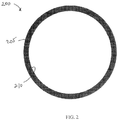
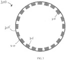
- Figures 2-4 depict plan views of illustrative pre-distributors 200, 300, and 400, respectively, which can be disposed within the first conduit 110.
- the pre-distributor 200 can be a band of material having a form of a ring that can have a substantially constant width between an outer surface or perimeter 205 and an inner surface or perimeter 210 thereof.
- the pre-distributor 300 can be a band of material having a form of a ring that can have a substantially constant width between an outer surface or perimeter 305 and an inner surface or perimeter 310 thereof.
- the pre-distributor 300 can also include a plurality of rectangular or semi-rectangular tabs 315 secured to the inner surface or perimeter 310 thereof.
- the tabs 315 can be referred to as "semi-rectangular” rather than “rectangular” because the side attached to the inner surface 310 can be curved to generally correspond thereto.
- the pre-distributor 400 can be a band of material having a form of a ring that can have a substantially constant width between an outer surface or perimeter 405 and an inner surface or perimeter 410 thereof.
- the pre-distributor 400 can also include a plurality of semi-elliptical tabs 415 secured to the inner surface or perimeter 410 thereof.
- each of the plurality of tabs 310 and 410 can have the same shape or a different shape with respect to one another.
- the plurality of tabs 310, 410 can provide a symmetrical inner surface or inner perimeter.
- tabs having the same or substantially the same shape can be disposed across from one another on the inner surfaces 315, 415 of the rings 305, 405, respectively, to provide a symmetrical inner surface.
- the plurality of tabs 315, 415 can have any desired geometrical shape.
- Illustrative shapes can include, but are not limited to, the semi-rectangular and semi-elliptical shapes depicted in Figures 3 and 4 .
- other geometrical shapes can include semi-triangular, semi-polygons having more than four sides such as a semi-pentagon, a semi-hexagon, a semi-heptagon, a semi-octagon, a semi-oval, a semi-parallelogram, a semi-trapezoid, a semi-kite, a semi-trapezium, a semi-crescent, or any combination thereof.
- the pre-distributors 200, 300, and 400 can each have any desired thickness, i.e., the length along the central longitudinal axis of the first conduit 110.
- the pre-distributors 200, 300, and 400 can each have a thickness of about 5 mm, about 10 mm, about 20 mm, about 30 mm, about 40 mm, about 45 mm, or about 50 mm to about 55 mm, about 60 mm, about 70 mm, about 80 mm, about 90 mm, or about 100 mm.
- the pre-distributors 300 and 400 can include any number of tabs 310 and 410, respectively.
- the pre-distributors 300 and 400 can include about 10, about 15, about 20, or about 25 to about 30, about 50, about 75, about 100 or more tabs 315 and 415, respectively, disposed about the inner surface or perimeter 310, 410, respectively.
- the pre-distributors 200, 300, and 400 can each be made of any suitable material.
- the pre-distributors 200, 300, and 400 can be made of a solid material, e.g ., solid metal.
- the pre-distributor can be made of a porous material, e.g., a ceramic or sintered metal.
- Illustrative metals can include, but are not limited to, stainless steel, stainless steel alloys, carbon steel, carbon still alloys, nickel, nickel alloys, low chrome steel, or any combination thereof.
- the metal can be or include a metal alloy that can include, but is not limited to, nickel, iron, chromium, cobalt, silicon, manganese, molybdenum, titanium, carbon, tungsten, and columbium.
- a metal alloy that can include, but is not limited to, nickel, iron, chromium, cobalt, silicon, manganese, molybdenum, titanium, carbon, tungsten, and columbium.
- Illustrative ceramic materials can be or include, but are not limited to, silicon dioxide, aluminum oxide, titanium dioxide, magnesium oxide, or any combination thereof.
- Figure 5 depicts a cross-sectional elevational view of another illustrative inlet assembly 500 for introducing one or more gases into a reactor, e.g., a dehydrogenation reactor, which includes a first pre-distributor 550 and a second pre-distributor 570, according to one or more embodiments.
- the inlet assembly 500 can include a first inlet conduit or "first conduit” 510, a second inlet conduit or "second conduit” 520, a third inlet conduit or "third conduit” 560, and an outlet conduit 530 that can be fluidly connected at a junction 540.
- the inlet assembly 500 like the inlet assembly 100, is often referred to as a "cactus" assembly because of the branched conduits, i.e., the first conduit 510, the second conduit 520, and the third conduit 560.
- the central longitudinal axis 512 of the first conduit 510 can be axially aligned with the central longitudinal axis 532 of the outlet conduit 530.
- the first pre-distributor 550 can be disposed within the first conduit 510 and the second pre-distributor 570 can be disposed within the outlet conduit 530. It should be noted that any number of first pre-distributors 550 can be disposed within the first conduit 210 and any number of second pre-distributors 570 can be disposed within the outlet conduit 530.
- the inlet assembly 500 can include 1, 2, 3, 4, 5, 6, 7, 8, 9, 10, or more first pre-distributors 550 disposed within the first conduit 510 and 1, 2, 3, 4, 5, 6, 7, 8, 9, 10, or more second pre-distributors 570 disposed within the outlet conduit 530.
- the inlet assembly 500 can include three first pre-distributors 550 and two second pre-distributors 570. In at least one other example, the inlet assembly 500 can include one first pre-distributor 550 and two second pre-distributors 570.
- the first conduit 510 can have a first average cross-sectional length, e.g., a first diameter, at a first or "top" end 516 and a second average cross-sectional length, e.g., a second diameter, at a second or "junction" end 517.
- the first average cross-sectional length at the first end 516 and the second average cross-sectional length at the second end 517 can be the same.
- the first average cross-sectional length at the first end 516 can be less than the second average cross-sectional length at the second end 517.
- the first conduit 510 can have a frusto-conical inner surface. In some examples, however, the first conduit 510 can have a cylindrical inner surface or any other profile.
- the second conduit 520 can have a first average cross-sectional length at a first or "top" end 524 and a second average cross-sectional length at a second or “junction" end 526 thereof.
- the first average cross-sectional length at the first end 524 and the second average cross-sectional length at the second end 526 thereof can be the same.
- the first average cross-sectional length at the first end 524 and the second average cross-sectional length at the second end 526 thereof can be different.
- the second conduit 520 can have a cylindrical inner surface. In other examples, the second conduit 520 can have a frusto-conical inner surface.
- the third conduit 560 can have a first average cross-sectional length at a first or "top" end 562 and a second average cross-sectional length at a second or “junction" end 564 thereof.
- the first average cross-sectional length at the first end 562 and the second average cross-sectional length at the second end 564 thereof can be the same.
- the first average cross-sectional length at the first end 562 and the second average cross-sectional length at the second end 564 thereof can be different.
- the third conduit 560 can have a cylindrical inner surface. In other examples, the third conduit 560 can have a frusto-conical inner surface.
- the outlet conduit 530 can have a first average cross-sectional length, e.g., first diameter, at a first or "junction" end 536 and a second average cross-sectional length, e.g., second diameter, at a second or "outlet" end 537.
- first average cross-sectional length at the first end 536 and the second average cross-sectional length at the second end 537 can be the same.
- first average cross-sectional length of the first end 536 can be less than the second average cross-sectional length at the second end 537.
- the outlet conduit 530 can have a frusto-conical inner surface. In some examples, however, the outlet conduit 530 can have a cylindrical inner surface or any other profile.
- the inner surface 544 of the junction 540 can transition from the second average cross-sectional length at the second end 517 of the first conduit 510 to the first average cross-sectional length at first end 536 of the outlet conduit 530 in a substantially smooth manner.
- the junction 540 can also have a frust-conical inner surface 544 to provide a substantially frusto-conical inner surface through the first conduit 510, the junction 540, and the outlet conduit 530.
- the acute angle (e) between the central longitudinal axis 512 of the first conduit 510 and the central longitudinal axis 522 of the second conduit 520 can be about 10°, about 20°C, about 30°, or about 40° to about 50°, about 60°, about 70°, or about 80°.
- the obtuse angle (f) between the central longitudinal axis 522 of the second conduit 520 and the central longitudinal axis 532 of the outlet conduit can be about 100°, about 110°, about 120°, or about 130° to about 140°, about 150°, about 160°, or about 170°.
- the acute angle (g) between the central longitudinal axis 512 of the first conduit 510 and the central longitudinal axis 563 of the third conduit 560 can be about 10°, about 20°C, about 30°, or about 40° to about 50°, about 60°, about 70°, or about 80°.
- the obtuse angle (h) between the central longitudinal axis 563 of the third conduit 560 and the central longitudinal axis 532 of the outlet conduit can be about 100°, about 110°, about 120°, or about 130° to about 140°, about 150°, about 160°, or about 170°.
- the acute angle (e) can be about 40° to about 50°, e.g., about 45°
- the obtuse angle (f) can be about 130° to about 140°, e.g., about 135°
- the acute angle (g) can be about 40° to about 50°, e.g., about 45°
- the obtuse angle (g) can be about 130° to about 140°, e.g., about 135°.
- the first pre-distributor 550 and the second pre-distributor 570 can be the same or substantially similar to the pre-distributors 150, 200, 300, and/or 400 discussed and described above with reference to Figures 1-4 .
- the first pre-distributor 550 and the second pre-distributor can be or include a band of material, a plurality of tabs, or a combination thereof.
- any one of the pre-distributors can be composed of a plurality of tabs that can be directly attached to the inner surface of the first conduit 110 and/or 510.
- the pre-distributors 150, 200, 300, 400, 550, and 570 can be free from any continuous band of material that traverses the inner perimeter of the first conduit 110 and/or 510.
- the pre-distributors 150, 200, 300, 400, 550, and 570 can be coupled, secured, or otherwise attached to the inner surface 114, 514 of the first conduit 110, 510, respectively, via any suitable attachment device or combination of attachment devices.
- the pre-distributors 150, 200, 300, 400, 550, and 570 can be welded, bolted, riveted, formed as an integral component of the first conduit, clamped, and/or held in place via friction fit.
- the pre-distributors 150, 200, 300, 400, 550, and/or 570 can be a ledge or other surface that can be milled, machined, cut, pressed, or otherwise formed into the inner surface 114, 514 of the first conduits 110, 510, respectively, and/or the inner surface 134, 534 of the outlet conduits 130, 530, respectively.
- the dimensions of the inlet assemblies 100 and 500 can be described as a ratio of a given dimension to the average cross-sectional length of the second ends 137, 537 of the outlet conduits 130, 530, respectively.
- the average cross-sectional lengths of the various conduits can be described as being diameters of a circle. Accordingly, the "D" below refers to the inner diameter at the second ends 137, 537 of the outlet conduits 130, 530, respectively. It should be understood, however, that any one or more of these cross-sectional lengths can be non-circular, e.g ., oval, a non-circular ellipse, a polygon, or any other geometrical shape.
- the first ends 116, 516 of the first conduits 110, 510 can have a diameter of about 0.3D, about 0.33D, about 0.35D, about 0.37D, or about 0.4D to about 0.41D, about 0.43D, about 0.45D, about 0.47D, or about 0.5D.
- a distance from a center of the junctions 140, 540 to the second ends 137, 537 of the outlet conduits 130, 530, respectively, can be about 0.7D, about 0.75D, about 0.8D, about 0.85D, about 0.9D, or about 0.95D to about 0.97D, about ID, about 1.05D, about 1.1D, about 1.15D, about 1.2D about 1.25D, or about 1.3D.
- a distance from the first ends 116, 516 of the first conduits 110, 510 to the second ends 137, 537 of the outlet conduits 130, 530, respectively, can be about 1.7D, about 1.8D, about 1.9D, about 2D, about 2.1D, about 2.2D, about 2.3D, or about 2.4D to about 2.5D, about 2.6D, about 2.7D, about 2.8D, about 2.9D, about 3D, about 3. ID, or about 3.2D.
- the second conduits 120, 520 can have a cylindrical inner surface and can have an inner diameter of about 0.3D, about 0.33D, about 0.35D, about 0.37D, about 0.4D, or about 0.42D to about 0.44D, about 0.47D, about 0.5D, about 0.53D, or about 0.55D.
- the third conduit 560 can have a cylindrical inner surface and can have an inner diameter of about 0.15D, about 0.17D, about 0.19D, about 0.2D, or about 0.21D to about 0.22D, about 0.24D, about 0.26D, about 0.28D, or about 0.3D.
- the components of the inlet assemblies 100 and 500 i.e., the first conduits 110, 510, the second conduits 120, 520, the third conduit 560, the junctions 140, 540, and the outlet conduits 130, 530 can be made of any suitable material.
- the components of the inlet assemblies 100 and 500 can be made of one or more metals, one or more ceramics, or a combination thereof.
- Illustrative metals can include, but are not limited to, stainless steel, stainless steel alloys, carbon steel, carbon still alloys, nickel, nickel alloys, low chrome steel, or any combination thereof.
- the metal can be or include a metal alloy that can include, but is not limited to, nickel, iron, chromium, cobalt, silicon, manganese, molybdenum, titanium, carbon, tungsten, and columbium.
- a metal alloy that can include, but is not limited to, nickel, iron, chromium, cobalt, silicon, manganese, molybdenum, titanium, carbon, tungsten, and columbium.
- Illustrative ceramic materials can be or include, but are not limited to, silicon dioxide, aluminum oxide, titanium dioxide, magnesium oxide, or any combination thereof.
- one or more fluids can be introduced via the first conduit 510 and can flow through the inlet assembly 500.
- the fluid can have a velocity profile at the second end 537 of the outlet conduit 530.
- the second end 537 of the outlet conduit 530 can have a radial distance from the inner surface 534 thereof to the central longitudinal axis 532 thereof.
- a velocity maxima of the velocity profile at the second end 537 of the outlet conduit 530 can be least 80% of the radial distance away from the inner surface 534 thereof.
- the velocity maxima of the velocity profile at the second end 537 of the outlet conduit 530 can be least 82%, at least 84%, at least 86%, at least 88%, at least 90%, at least 92%, at least 93%, at least 94%, at least 94.5%, at least 95%, at least 95.5%, at least 96%, at least 96.5%, at least 97%, at least 97.5%, or more of the radial distance away from the inner surface 534 thereof.
- the velocity maxima of the velocity profile of the oxygen-containing fluid at the second end 137 of the outlet conduit 130 can be at least 80%, at least 82%, at least 83%, at least 84%, at least 85%, at least 86%, at least 87%, at least 88%, at least 89%, at least 90%, at least 91%, at least 92%, at least 93%, at least 94%, at least 94.5%, at least 95%, at least 95.5%, at least 96%, at least 96.5%, at least 97%, at least 97.5%, or more of a radial distance away from the inner surface 134 thereof when a velocity of the fluid is greater than or equal to 100 m/s, 125 m/s, 150 m/s, 175 m/s, and/or 200 m/s.
- the velocity maxima of the velocity profile can be measured, computed, determined, or otherwise estimated via computational fluid dynamics (CFD) modeling.
- CFD computational fluid dynamics
- the CFD modeling can use a CFD solver and a meshing solver.
- the CFD solver can be the Ansys CFX V17.2 and the meshing solver can be the Ansys Mesher V17.2.
- Figure 6 depicts a cross-sectional elevational view of an illustrative reactor system 600 for dehydrogenating one or more alkanes that includes the inlet assembly 500 discussed and described above with reference to Figure 5 coupled to a dehydrogenation reactor 610, according to one or more embodiments.
- the reactor 610 can include one or more gas distributors 615 and one or more catalyst beds 620.
- the catalyst bed 620 can be a fixed catalyst bed.
- the reactor can also include an outlet 625 for recovering a crude dehydrogenated product via line 626 therefrom.
- the reactor 610 can also include one or more purge gas or off-gas outlets 630 for recovering one or more purge gases, off-gases, regeneration gases, or other fluids via line 631, e.g., fluids introduced and/or produced during a catalyst decoking and regeneration process.
- Suitable dehydrogenation process conditions, feeds, and other parameters can be or include those discussed and described in U.S. Patent Nos.: 2,423,029 , 4,560,824 , and 4,581,339 ; and WO Publication No. WO 2016/069918 .
- One or more alkanes via line 635 can be introduced to the second conduit 520 of the inlet assembly 500.
- the alkane can pass through inlet assembly 500 and into the reactor 610.
- the alkane can contact the catalyst to produce a crude product that can include one or more alkenes, such as propylene or butylene, and a coked catalyst that can include coke disposed on the catalyst.
- the dehydrogenation of the alkane is an endothermic reaction. Accordingly, the alkane and/or the catalyst can be heated to a temperature sufficient to provide at least a portion of the heat required to dehydrogenate the alkane in the presence of the catalyst.
- the catalyst can be a fresh or new catalyst, a regenerated catalyst, or a mixture thereof.
- Illustrative alkanes can be or include, but are not limited to, ethane, propane, butane, 2-methylpropane, pentane, 2-methylbutane, 2,2-dimethylpropane, isomers thereof, or any mixture thereof.
- the dehydrogenated product can be or include, but is not limited to, ethene (ethylene), propene (propylene), but-1-ene (butylene), ( Z )-but-2-ene, ( E )-but-2-ene, 2-methylpropene, 1-pentene, cis -2-pentene, trans -2-pentene, isomers thereof, or any mixture thereof.
- the alkane can be or include propane and the dehydrogenated product can be or include propylene.
- the alkane can include at least 80 wt% of propane, at least 85 wt% of propane, at least 90 wt% of propane, at least 95 wt% of propane, at least 97 wt% of propane, at least 98 wt% of propane, at least 99 wt% of propane, at least 99.5 wt% of propane, at least 99.7 wt% of propane, or at least 99.9 wt% of propane.
- the alkane can include at least 80 wt% of butane, at least 85 wt% of butane, at least 90 wt% of butane, at least 95 wt% of butane, at least 97 wt% of butane, at least 98 wt% of butane, at least 99 wt% of butane, at least 99.5 wt% of butane, at least 99.7 wt% of butane, or at least 99.9 wt% of butane.
- the dehydrogenation of the alkane to the alkene can be incomplete.
- the crude dehydrogenated product can include the alkene and the alkane that was not dehydrogenated.
- At least a portion of the alkane present in the crude dehydrogenated product can be separated therefrom to produce a purified dehydrogenated product.
- the alkane separated from the crude dehydrogenated product can be recycled or combined with fresh or incoming alkane and contacted with the catalyst.
- the catalyst can be at a temperature of about 425°C, about 450°C, about 475°C, about 500°C, about 535°C, about 550°C, about 565°C, about 585°C or about 590°C to about 595°C, about 600°C, about 625°C, about 650°C, about 675°C, about 700°C, about 750°C, or about 800°C when contacted with the alkane.
- the catalyst can include one or more metals.
- the one or more metals can include, but are not limited to, platinum, palladium, gold, indium, chromium, tin, iron, molybdenum, tungsten, nickel, silver, any alloy thereof, any oxide thereof, or any mixture thereof.
- Illustrative supports can include, but are not limited to, one or more inorganic oxides.
- Illustrative inorganic oxides can include, but are not limited to, alumina, silica, titania, zirconia, boria, zinc oxide, magnesia, or any mixture thereof.
- Illustrative combinations of inorganic oxides can include, but are not limited to, alumina-silica, silica-titania, alumina-silica-titania, alumina-zirconia, alumina-titania, or any mixture thereof.
- the support can be or include alumina, silica, or a combination thereof.
- the catalyst can be disposed within the reactor within a fixed bed and the alkane can be introduced to a first side of the fixed bed and the dehydrogenated product can be recovered from a second side of the fixed bed.
- the first side and the second side of the fixed bed can be on opposite sides of the fixed bed with respect to one another.
- the alkane can be diverted to another reactor and the coked catalyst can be contacted with a purge fluid introduced via line 640 to the third conduit 560 to remove at least a portion of any residual alkane on, about, and/or within the catalyst bed 620 and/or within the reactor 610.
- the purge fluid can be or include, but is not limited to, nitrogen, argon, helium, carbon dioxide, exhaust or combustion gas, air, water or steam, or any mixture thereof.
- the purge fluid can be or include steam.
- the purge fluid e.g ., steam
- the purge fluid can be at a temperature of about 120°C, about 150°C, about 175°C, about 200°C, about 225°C, about 250°C, or about 275°C to about 400°C, about 450°C, about 500°C, about 525°C, about 550°C, about 575°C, or about 600°C.
- the purge fluid e.g ., steam
- the purge fluid can be at a pressure of about 101 kPa, about 125 kPa, about 200 kPa, about 350 kPa, about 500 kPa, about 1,000 kPa, about 1,500 kPa, about 2,000 kPa, or about 2,500 kPa to about 3,000 kPa, about 3,500 kPa, about 4,000 kPa, or about 4,500 kPa.
- the catalyst After contacting the catalyst with the purge fluid, the catalyst can be decoked. Decoking the coked catalyst can remove at least a portion of the coke deposited on, in, and/or about the catalyst.
- the coke can be removed from the catalyst by combustion of the coke.
- the catalyst can be contacted with an oxygen-containing fluid at conditions sufficient to combust at least a portion of the coke, thereby removing coke from the coked catalyst.
- oxygen-containing fluids can be or include, but are not limited to, ambient air, bottled air, in-line or in-house air, oxygen (O 2 ), nitrous oxide, ozone, or any mixture thereof.
- the oxygen-containing fluid can be or include air.
- the oxygen-containing fluid can be introduced via line 645 to the first conduit 510. The oxygen-containing fluid can flow through the inlet assembly 500 and into the reactor 610.
- the oxygen-containing fluid can be at a temperature of about 500°C, about 550°C, about 600°C, about 650°C, about 660°C, about 665°C, about 670°C, or about 675°C to a temperature of about 680°C, about 685°C, about 690°C, about 695°C, about 700°C, about 725°C, about 750°C, about 775°C, or about 800°C when flowing through the inlet assembly 500 and/or when contacted with the coked catalyst to produce the regenerated catalyst.
- the oxygen-containing fluid can be at a pressure of about 101 kPa, about 250 kPa, about 500 kPa, or about 750 kPa to about 1,000 kPa, about 1,250 kPa, about 1,500 kPa, about 1,750 kPa, about 2,500 kPa, about 3,000 kPa, about 3,500 kPa, about 4,000 kPa, or about 4,500 kPa when flowing through the inlet assembly 500 and/or when contacted with the coked catalyst to produce the regenerated catalyst.
- the oxygen-containing fluid can be at a pressure of about 101 kPa, about 110 kPa, or about 115 kPa to about 125 kPa, about 135 kPa, or about 150 kPa when flowing through the inlet assembly 500 and/or when contacted with the coked catalyst to produce the regenerated catalyst.
- the oxygen-containing fluid can flow through the inlet assembly 500 at a velocity of about 100 m/s, about 125 m/s, about 150 m/s, about 175 m/s, or about 190 m/s to about 210 m/s, about 225 m/s, or about 250 m/s.
- the amount of the oxygen-containing fluid that can be introduced to the reactor 610 and contacted with the coke catalyst to produce the decoked catalyst can widely vary.
- the amount of the oxygen-containing fluid introduced to the reactor 610 and contacted with the coked catalyst to produce the decoked catalyst can be about 300 m 3 /s, about 325 m 3 /s, or about 350 m 3 /s to about 375 m 3 /s, about 400 m 3 /s, or about 425 m 3 /s.
- the oxygen-containing fluid can have a velocity profile at the second end 537 of the outlet conduit 530.
- the second end 537 of the outlet conduit 530 can have a radial distance from the inner surface 534 thereof to the central longitudinal axis 532 thereof.
- the velocity maxima of the velocity profile at the second end 537 of the outlet conduit 530 can be at least 80% of the radial distance.
- the velocity maxima of the velocity profile at the second end 537 of the outlet conduit 530 can be at least 82%, at least 84%, at least 86%, at least 88%, at least 90%, at least 92%, at least 93%, at least 94%, at least 94.5%, at least 95%, at least 95.5%, at least 96%, at least 96.5%, at least 97%, at least 97.5%, or more of the radial distance.
- the velocity maxima of the velocity profile of the oxygen-containing fluid at the second end 537 of the outlet conduit 530 can be at least 80%, at least 82%, at least 83%, at least 84%, at least 85%, at least 86%, at least 87%, at least 88%, at least 89%, at least 90%, at least 91%, at least 92%, at least 93%, at least 94%, at least 94.5%, at least 95%, at least 95.5%, at least 96%, at least 96.5%, at least 97%, at least 97.5%, or more of a radial distance away from the inner surface 534 thereof when a velocity of the oxygen-containing fluid is greater than or equal to 100 m/s, 125 m/s, 150 m/s, 175 m/s, and/or 200 m/s.
- the velocity maxim of the velocity profile can be measured, computed, determined, or otherwise estimated via computational fluid dynamics (CFD) modeling.
- CFD computational fluid dynamics
- the CFD modeling can use a CFD solver and a meshing solver.
- the CFD solver can be the Ansys CFX V17.2 and the meshing solver can be the Ansys Mesher V17.2.
- the oxygen-containing fluid introduced via line 645 to the first conduit 510 can flow through the inlet assembly 500 in the turbulent flow regime.
- one or more hydrocarbon fuels can be contacted with the coked catalyst while the oxygen-containing fluid contacts the coked catalyst.
- the hydrocarbon fuel can combust in the presence of the oxygen-containing fluid to increase the temperature of the decoked catalyst.
- the hydrocarbon fuel can be introduced via line 640 to the third conduit 560 and the oxygen-containing fluid can be introduced via line 645 to the first conduit 510.
- contact between the oxygen-containing fluid and the coked catalyst can be started, then contact between the hydrocarbon fuel and the coked catalyst can be started, then contact between the hydrocarbon fuel can be stopped, and then contact between the oxygen-containing fluid can be stopped.
- contact between the oxygen-containing fluid and the hydrocarbon fuel can be started at the same or substantially the same time, e.g., within 10 seconds of one another, then contact between the hydrocarbon fuel can be stopped, and then contact between the oxygen-containing fluid can be stopped.
- the hydrocarbon fuel can be a gas and/or a liquid hydrocarbon.
- Illustrative hydrocarbon fuels can include, but are not limited to, one or more C 1 -C 6 hydrocarbons such as methane, ethane, propane, butane, pentane, hexane, or any mixture thereof.
- the hydrocarbon fuel can be or include methane and can be contacted with the coked catalyst while the oxygen-containing fluid contacts the coked catalyst.
- the hydrocarbon fuel can include at least 90 wt%, at least 93 wt%, at least 95 wt%, at least 97 wt%, or at least 99 wt% methane.
- the hydrocarbon fuel can be or include natural gas.
- the decoked catalyst can be contacted with one or more reducing gases to produce a regenerated catalyst and an off-gas.
- the reducing gas can be introduced via line 640 to the third conduit 560 and into the reactor 610 via the inlet assembly 500.
- the reducing gas can contact the decoked catalyst therein to produce the regenerated catalyst and the off-gas.
- the reducing gas can remove at least a portion of any adsorbed oxygen from the decoked catalyst.
- the catalyst includes chromium
- the reducing gas can convert at least a portion of any chromium (VI) to chromium (III).
- the off-gas can include at least a portion of the adsorbed oxygen that can be removed from the decoked catalyst.
- the off-gas, oxygen-containing fluid, combustion gas products, reducing gas, and purge gas can be removed from the reactor 620 via line 631 from outlet 630. Once the coked catalyst has been decoked and regenerated additional alkane can be introduced to the reactor 610 to produce additional dehydrogenated products.
- Illustrative reducing gases can be or include, but are not limited to, hydrogen, methane, ethane, ethylene, propane, propylene, carbon monoxide, butane, or any mixture thereof.
- the reducing gas can be or include a hydrogen product recovered from one or more pressure swing absorption units that separates a gas mixture containing hydrogen and one or more other components such as methane, ethane, carbon dioxide, nitrogen, oxygen, ammonia, or any mixture thereof.
- the reducing gas can be or include hydrogen recovered via membrane separation of a gas mixture containing hydrogen and one or more other components such as methane, ethane, carbon dioxide, nitrogen, oxygen, ammonia, or any mixture thereof.
- Computational Fluid Dynamics (CFD) modeling is used to simulate the velocity contour profile of air flowing through large and a small sized models of an inlet assembly for introducing a fluid into a reactor.
- the CFD solver is Ansys CFX V17.2 and the meshing solver is Ansys Mesher V17.2.
- the mesh details for geometry with no internals based on inlet diameter being equal to D are as follows: mesh type is fully tetrahedral with wall inflation; size function refinement is proximity and curvature; number of elements is greater than 1800000, number of wall inflation layers is 7, maximum face size is about 0.0800D; minimum face sizing is about 0.0123D; and maximum tetrahedral size is about 0.0984D.
- Figure 7 depicts a CFD inlet assembly model that is used in the CFD modeling of both large and small sized inlet assemblies in Examples C1, C2, and Ex. 1-4.
- the CFD model includes a viscous section 705 and an inviscid section 710.
- the inviscid section 710 is added for numerical stability only.
- Table 2 lists the relevant geometric dimensions of the large and small inlet assemblies that are used in the simulations.
- the longitudinal axis of the first inlet conduit and the longitudinal axis of the outlet conduit are axially aligned with one another.
- the dimensions listed in Table 2 are indicated in Figure 8 .
- Table 2 Dimensions Model Large Model Small Model First Inlet Conduit Diameter (805) 0.403 x D L 0.405 x D S Outlet Conduit Diameter (810) D L Ds Length of Inlet assembly (815) 2.416 x D L 2.643 x Ds Length from Outlet End to Center of Junction (820) 0.966 x D L 1.063 x D S Second Inlet Conduit Diameter (825) 0.430 x D L 0.532 x D S Third Conduit Diameter (830) 0.215 x D L 0.228 x D S
- the first simulation (C1) is a comparative example that does not include any pre-distributor.
- the second and third simulations are inventive examples that include a pre-distributor.
- Ex. 1 includes five rings, each having a constant width. Three rings are disposed on an inner surface of the first conduit about an inner perimeter thereof and two rings are disposed on an inner surface of the outlet conduit about an inner perimeter thereof.
- Ex. 2 includes three lobed rings, i.e., rings having semi-elliptical tabs disposed about an inner surface thereof. One lobed ring is disposed on an inner surface of the first conduit about an inner perimeter thereof and two lobed rings are disposed on an inner surface of the outlet conduit about an inner perimeter thereof.
- Table 3 lists the distance from the longitudinal axis of the first inlet conduit or the outlet conduit (depending on the particular ring) to the inner surface of each ring disposed therein (AA), the distance each ring is from the end of the first inlet conduit (BB), and the width of each ring (CC).
- Figure 9 illustrates the distances AA, BB, and CC provided in Table 3.
- Table 3 Dimensions for Large Model with 5 Rings Ring Position Ring Thickness Distance from longitudinal axis to inner surface of ring (AA) Distance from end of first inlet conduit to ring (BB) Width of ring (CC) 1 0.01321 x D L 0.45326 x D L 0.20476 x D L 0.02531 x D L 2 0.01321 x D L 0.48711 x D L 0.33686 x D L 0.04164 x D L 3 0.01321 x D L 0.51857 x D L 0.46896 x D L 0.05797 x D L 4 0.01321 x D L 0.91048 x D L 2.05416 x D L 0.05894 x D L 5 0.01321 x D L 0.0.94313 x D L 2.18626 x D L 0.07527 x D L
- Table 4 lists the distance from the longitudinal axis of the first inlet conduit or the outlet conduit (depending on the particular ring) to the inner surface of each lobed ring at a position corresponding to the center of each lobe (AA), the distance each ring is from the end of the first inlet conduit (BB), the width of each ring (CC), and the radius of each lobe (DD).
- Figures 10 and 11 illustrate the distances AA, BB, CC, and DD provided in Table 4.
- Each lobed ring has 30 lobes, i.e., semi-elliptical tabs disposed about an inner surface of the ring.
- Table 4 Dimensions for Large Model with 3 lobed Rings Ring Position Ring Thickness Distance from longitudinal axis to inner surface of ring at center of lobe (AA) Distance from end of first inlet conduit to ring (BB) Width of ring (CC) Radius of lobe (DD) 1 0.01321 x D L 0.60637 x D L 0.82404 x D L 0.02396 x D L 0.02351 x D L 2 0.01321 x D L 0.86110 x D L 1.85443 x D L 0.03348 x D L 0.03322 x D L 3 0.01321 x D L 0.91336 x D L 2.06579 x D L 0.03543 x D L 0.03527 x D L
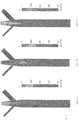
- Figures 12, 13, and 14 depict the simulated air velocity contours through the inlet assemblies along the ZX-plane in examples C1, Ex. 1, and Ex. 2, respectively.
- Figures 15, 16, and 17 depict the simulated air velocity contours through the inlet assemblies along the YZ-plane in examples C1, Ex. 1, and Ex. 2, respectively.
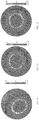
- Figures 18, 19, and 20 depict the simulated air velocity fields at the end of the outlet conduit of the inlet assemblies in examples C1, Ex. 1, and Ex. 2, respectively.
- Figures 21, 22, and 23 depict the approximate 3D-structure of the simulated velocity profiles at the end of the outlet conduit of the inlet assemblies in Examples C1, Ex. 1, and Ex. 2, respectively.
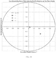
- Figure 24 depicts a coordinate position of the simulated velocity profile maxima at the end of the outlet conduit of the inlet assemblies in Examples C1, Ex. 1, and Ex. 2, respectively.
- the velocity centroids for the two inventive examples are significantly more centered than the comparative example (C1) that does not include a pre-distributor.
- the positional accuracy of the velocity profile maxima i.e., the percent of radial position where the velocity maxima is found, for Ex. 1 and Ex. 2 are 97.6% and 94.5%, respectively.
- the positional accuracy of the velocity profile maxima for comparative example (C1) is only 47.2%.
- the pressure loss for the comparative example (C1) and inventive examples (Ex. 1 and Ex. 2) is 2,349.7 Pa, 7,638.2 Pa, and 2,510.2 Pa, respectively.
- the first simulation (C2) is a comparative example that does not include any pre-distributor.
- the second and third simulations are inventive examples that include a pre-distributor.
- Ex. 3 includes four rings, each having a constant width, as the pre-distributors. Two rings are disposed on an inner surface of the first conduit about an inner perimeter thereof and two rings are disposed on an inner surface of the outlet conduit about an inner perimeter thereof.
- Ex. 2 includes three lobed rings, i.e., rings having semi-elliptical tabs disposed about an inner surface thereof. One lobed ring is disposed on an inner surface of the first conduit about an inner perimeter thereof and two lobed rings are disposed on an inner surface of the outlet conduit about an inner perimeter thereof.
- Table 5 lists the distance from the longitudinal axis of the first inlet conduit or the outlet conduit (depending on the particular ring) to the inner surface of each ring disposed therein (AA), the distance each ring is from the end of the first inlet conduit (BB), and the width of each ring (CC).
- the distances AA, BB, and CC provided in Table 5 are the same as those in the large simulations and are shown in Figure 9 .
- Table 5 Dimensions for Small Model with 4 Rings Ring Position Ring Thickness Distance from longitudinal axis to inner surface of ring (AA) Distance from end of first inlet conduit to ring (BB) Width of ring (CC) 1 0.02491 x D S 0.46426 x D S 0.26334 x D S 0.02964 x D S 2 0.02491 x D S 0.50912 x D S 0.46264 x D S 0.05207 x D S 3 0.02491 x D S 0.91289 x D S 2.25635 x D S 0.03292 x D S 4 0.02491 x D S 0.95775 x D S 2.45566 x D S 0.05535 x D S
- Table 6 lists the distance from the longitudinal axis of the first inlet conduit or the outlet conduit (depending on the particular ring) to the inner surface of each lobed ring at a position corresponding to the center of each lobe (AA), the distance each ring is from the end of the first inlet conduit (BB), the width of each ring (CC), and the radius of each lobe (DD).
- the distances AA, BB, CC, and DD provided in Table 6 are the same distances referred to with regard to the large model simulations and are also indicated in Figures 10 and 11 .
- Each lobed ring has 30 lobes, i.e., semi-elliptical tabs disposed about an inner surface of the ring.
- Table 6 Dimensions for Small Model with 3 Rings Ring Position Ring Thickness Distance from longitudinal axis to inner surface of ring at center of lobe (AA) Distance from end of first inlet conduit to ring (BB) Width of ring (CC) Radius of lobe (DD) 1 0.01321 x D S 0.61006 x D S 0.91106 x D S 0.02838 x D S 0.02292 x D S 2 0.01321 x D S 0.86801 x D S 2.05705 x D S 0.04284 x D S 0.03413 x D S 3 0.01321 x D S 0.92409 x D S 2.30618 x D S 0.04598 x D S 0.03687 x D S
- Figures 25, 26, and 27 depict the simulated air velocity contours through the inlet assemblies along the ZX-plane in examples C2, Ex. 3, and Ex. 4, respectively.
- Figures 28, 29, and 30 depict the simulated air velocity contours through the inlet assemblies along the YZ-plane in examples C2, Ex. 3, and Ex. 4, respectively.
- Figures 31, 32, and 33 depict the simulated air velocity fields at the end of the outlet conduits of the inlet assemblies in examples C2, Ex. 3, and Ex. 4, respectively.
- Figures 34, 35, and 36 depict an approximate 3D-structure of the simulated velocity profiles at the end of the outlet conduits of the inlet assemblies in Examples C2, Ex. 3, and Ex. 4, respectively.
- Figure 37 depicts a coordinate position of the simulated velocity profile maxima at the end of the outlet conduits of the inlet assemblies of Examples C2, Ex. 3, and Ex. 4, respectively.
- the velocity centroids of the two inventive examples are significantly more centered than the comparative example (C2) that does not include a pre-distributor.
- the positional accuracy of the velocity profile maxima i.e., the percent of radial position where the velocity maxima is found, for Ex. 3 and Ex. 4 are 98.6% and 97.9%, respectively.
- the positional accuracy of the velocity profile maxima for comparative example (C2) is only 70.6%.
- the pressure loss for the comparative example (C2) and inventive examples (Ex. 3 and Ex. 4) is 2,204.4 Pa, 7,769.4 Pa, and 2,796.0 Pa, respectively.
Landscapes
- Chemical & Material Sciences (AREA)
- Organic Chemistry (AREA)
- Chemical Kinetics & Catalysis (AREA)
- Engineering & Computer Science (AREA)
- Materials Engineering (AREA)
- Physics & Mathematics (AREA)
- Fluid Mechanics (AREA)
- Thermal Sciences (AREA)
- Devices And Processes Conducted In The Presence Of Fluids And Solid Particles (AREA)
- Physical Or Chemical Processes And Apparatus (AREA)
- Industrial Gases (AREA)
Applications Claiming Priority (3)
| Application Number | Priority Date | Filing Date | Title |
|---|---|---|---|
| US201762491688P | 2017-04-28 | 2017-04-28 | |
| PCT/IB2018/052959 WO2018198097A2 (fr) | 2017-04-28 | 2018-04-28 | Traitements et appareil d'introduction du gaz dans un réacteur |
| EP18726222.5A EP3615212A2 (fr) | 2017-04-28 | 2018-04-28 | Procédés et appareil pour introduire du gaz dans un réacteur |
Related Parent Applications (1)
| Application Number | Title | Priority Date | Filing Date |
|---|---|---|---|
| EP18726222.5A Division EP3615212A2 (fr) | 2017-04-28 | 2018-04-28 | Procédés et appareil pour introduire du gaz dans un réacteur |
Publications (1)
| Publication Number | Publication Date |
|---|---|
| EP3838404A1 true EP3838404A1 (fr) | 2021-06-23 |
Family
ID=62218017
Family Applications (2)
| Application Number | Title | Priority Date | Filing Date |
|---|---|---|---|
| EP21156490.1A Withdrawn EP3838404A1 (fr) | 2017-04-28 | 2018-04-28 | Appareil pour introduire du gaz dans un réacteur |
| EP18726222.5A Withdrawn EP3615212A2 (fr) | 2017-04-28 | 2018-04-28 | Procédés et appareil pour introduire du gaz dans un réacteur |
Family Applications After (1)
| Application Number | Title | Priority Date | Filing Date |
|---|---|---|---|
| EP18726222.5A Withdrawn EP3615212A2 (fr) | 2017-04-28 | 2018-04-28 | Procédés et appareil pour introduire du gaz dans un réacteur |
Country Status (6)
| Country | Link |
|---|---|
| US (2) | US20180339280A1 (fr) |
| EP (2) | EP3838404A1 (fr) |
| KR (1) | KR20190139286A (fr) |
| CN (1) | CN111201083A (fr) |
| CA (1) | CA3061584A1 (fr) |
| WO (1) | WO2018198097A2 (fr) |
Families Citing this family (2)
| Publication number | Priority date | Publication date | Assignee | Title |
|---|---|---|---|---|
| EP3848113A1 (fr) * | 2020-01-07 | 2021-07-14 | SABIC Global Technologies B.V. | Systèmes, dispositifs et procédés d'un système de distribution d'alimentation de réacteur |
| WO2021165830A1 (fr) * | 2020-02-20 | 2021-08-26 | Sabic Global Technologies B.V. | Systèmes, dispositifs, et procédés d'un ensemble d'écoulement pour processus de déshydrogénation |
Citations (11)
| Publication number | Priority date | Publication date | Assignee | Title |
|---|---|---|---|---|
| US2423029A (en) | 1942-07-18 | 1947-06-24 | Houdry Process Corp | Process for producing diolefins |
| US4560824A (en) | 1985-05-07 | 1985-12-24 | Air Products And Chemicals, Inc. | Heat balance control in catalytic dehydrogenation of isobutane |
| US4581339A (en) | 1985-03-18 | 1986-04-08 | Air Products And Chemicals, Inc. | Catalytic dehydrogenation reactor cycle |
| US6012652A (en) * | 1998-01-30 | 2000-01-11 | Mobil Oil Corporation | Atomizing nozzle and method of use thereof |
| US6669915B1 (en) * | 1999-07-13 | 2003-12-30 | Exxonmobil Research And Engineering Company | Gas-liquid inlet nozzle for cocurrent downflow reactors |
| US20050011972A1 (en) * | 2001-05-04 | 2005-01-20 | Daniel Barthod | Device for homogeneous distribution of a fluid in a chamber and uses thereof |
| WO2010039525A2 (fr) * | 2008-09-30 | 2010-04-08 | Uop Llc | Dispositif et procédé pour mélanger un catalyseur régénéré et carbonisé |
| US8343241B2 (en) * | 2009-02-11 | 2013-01-01 | Natural Energy Systems Inc. | Process for the conversion of organic material to methane rich fuel gas |
| CN204619940U (zh) * | 2015-05-06 | 2015-09-09 | 天津渤化石化有限公司 | 一种丙烯反应器 |
| WO2016069918A1 (fr) | 2014-10-29 | 2016-05-06 | Flint Hills Resources, Lp | Procédés de déshydrogénation d'un ou plusieurs alcanes |
| WO2016181344A1 (fr) * | 2015-05-14 | 2016-11-17 | Sabic Global Technologies B.V. | Réacteurs et dispositifs internes de réacteur pour la déshydrogénation d'hydrocarbures |
Family Cites Families (10)
| Publication number | Priority date | Publication date | Assignee | Title |
|---|---|---|---|---|
| US5322960A (en) * | 1993-04-15 | 1994-06-21 | Nippon Shokubai Co., Ltd. | Method for inhibiting polymerization of (meth) acrylic acid and esters thereof |
| MY135762A (en) * | 2002-01-09 | 2008-06-30 | Basf Ag | Method for producing acrylic acid |
| FR2877003B1 (fr) * | 2004-10-26 | 2007-01-05 | Arkema Sa | Procede ameliore de fabrication d'anhydride (meth) acrylique |
| DE102006029318B3 (de) * | 2006-06-23 | 2007-10-11 | Röhm Gmbh | Verfahren zur kontinuierlichen Herstellung von ungesättigten Carbonsäureanhydriden |
| US8092755B2 (en) * | 2009-04-06 | 2012-01-10 | Lummus Technology Inc. | Devices for injection of gaseous streams into a bed of fluidized solids |
| US9861947B2 (en) * | 2012-02-28 | 2018-01-09 | Phillips 66 Company | Reactor inlet vapor velocity equalizer and distributor |
| US9636654B2 (en) * | 2012-02-28 | 2017-05-02 | Phillips 66 Company | Modifying flow of a reactor inlet distributor |
| WO2014090841A2 (fr) * | 2012-12-12 | 2014-06-19 | Basf Se | Réacteur pour la réalisation d'une déshydrogénation autothermique en phase gazeuse |
| US9725380B2 (en) * | 2014-03-14 | 2017-08-08 | Clariant Corporation | Dehydrogenation process with heat generating material |
| US20170275219A1 (en) * | 2014-08-21 | 2017-09-28 | Savic Global Technologies B.V. | Systems and methods for dehydrogenation of alkanes |
-
2018
- 2018-04-27 US US15/965,572 patent/US20180339280A1/en not_active Abandoned
- 2018-04-28 WO PCT/IB2018/052959 patent/WO2018198097A2/fr not_active Ceased
- 2018-04-28 CN CN201880033517.7A patent/CN111201083A/zh active Pending
- 2018-04-28 CA CA3061584A patent/CA3061584A1/fr not_active Abandoned
- 2018-04-28 KR KR1020197033949A patent/KR20190139286A/ko not_active Withdrawn
- 2018-04-28 EP EP21156490.1A patent/EP3838404A1/fr not_active Withdrawn
- 2018-04-28 EP EP18726222.5A patent/EP3615212A2/fr not_active Withdrawn
-
2020
- 2020-07-14 US US16/927,994 patent/US20200338514A1/en not_active Abandoned
Patent Citations (11)
| Publication number | Priority date | Publication date | Assignee | Title |
|---|---|---|---|---|
| US2423029A (en) | 1942-07-18 | 1947-06-24 | Houdry Process Corp | Process for producing diolefins |
| US4581339A (en) | 1985-03-18 | 1986-04-08 | Air Products And Chemicals, Inc. | Catalytic dehydrogenation reactor cycle |
| US4560824A (en) | 1985-05-07 | 1985-12-24 | Air Products And Chemicals, Inc. | Heat balance control in catalytic dehydrogenation of isobutane |
| US6012652A (en) * | 1998-01-30 | 2000-01-11 | Mobil Oil Corporation | Atomizing nozzle and method of use thereof |
| US6669915B1 (en) * | 1999-07-13 | 2003-12-30 | Exxonmobil Research And Engineering Company | Gas-liquid inlet nozzle for cocurrent downflow reactors |
| US20050011972A1 (en) * | 2001-05-04 | 2005-01-20 | Daniel Barthod | Device for homogeneous distribution of a fluid in a chamber and uses thereof |
| WO2010039525A2 (fr) * | 2008-09-30 | 2010-04-08 | Uop Llc | Dispositif et procédé pour mélanger un catalyseur régénéré et carbonisé |
| US8343241B2 (en) * | 2009-02-11 | 2013-01-01 | Natural Energy Systems Inc. | Process for the conversion of organic material to methane rich fuel gas |
| WO2016069918A1 (fr) | 2014-10-29 | 2016-05-06 | Flint Hills Resources, Lp | Procédés de déshydrogénation d'un ou plusieurs alcanes |
| CN204619940U (zh) * | 2015-05-06 | 2015-09-09 | 天津渤化石化有限公司 | 一种丙烯反应器 |
| WO2016181344A1 (fr) * | 2015-05-14 | 2016-11-17 | Sabic Global Technologies B.V. | Réacteurs et dispositifs internes de réacteur pour la déshydrogénation d'hydrocarbures |
Also Published As
| Publication number | Publication date |
|---|---|
| CN111201083A (zh) | 2020-05-26 |
| WO2018198097A3 (fr) | 2020-03-19 |
| US20180339280A1 (en) | 2018-11-29 |
| CA3061584A1 (fr) | 2018-11-01 |
| US20200338514A1 (en) | 2020-10-29 |
| WO2018198097A2 (fr) | 2018-11-01 |
| KR20190139286A (ko) | 2019-12-17 |
| EP3615212A2 (fr) | 2020-03-04 |
Similar Documents
| Publication | Publication Date | Title |
|---|---|---|
| NL2012164C2 (en) | Premixer, radially fixed bed reactor, and reaction system for oxidative dehydrogenation of butene. | |
| CN105623732B (zh) | 一种石油烃吸附脱硫方法 | |
| US20200338514A1 (en) | Processes and apparatus for introducing a gas into a reactor | |
| CN103124593B (zh) | 进料管嘴装置 | |
| US20140249022A1 (en) | Reduced fluidization of solid particles in radial flow fluid/solid contacting | |
| JP2020189290A (ja) | 触媒モジュール及びその適用 | |
| CN102105563B (zh) | 纯化包含乙烯的废气进料流的工艺 | |
| EP3294444B1 (fr) | Réacteurs et dispositifs internes de réacteur pour la déshydrogénation d'hydrocarbures | |
| WO2024206754A3 (fr) | Pyrolyse catalytique d'hydrocarbures améliorée par milieux inertes | |
| WO2015026589A1 (fr) | Processus et appareil d'écoulement radial | |
| CN105967972A (zh) | 乙炔制备苯及联产乙烯的方法 | |
| EP2814794A1 (fr) | Procédé et système de purification d'un courant de gaz contenant de l'éthylène | |
| CN106517093A (zh) | 一种甲烷水蒸气重整制氢反应装置及方法 | |
| CN111054275A (zh) | 一种催化反应装置及其催化反应系统 | |
| JP7428592B2 (ja) | 四塩化チタンの製造方法及び塩化炉 | |
| US10543469B2 (en) | Scallop support distributor for radial flow reactor | |
| KR101921430B1 (ko) | 탈수소화 반응기 | |
| CN115888379A (zh) | 脱除含氧气体中的氧气的方法 | |
| US20240376026A1 (en) | Methods for processing chemicals | |
| KR101652597B1 (ko) | 보강판을 구비한 촉매 스크린 | |
| CN110832056A (zh) | 芳香族烃的制造方法 | |
| TWI519480B (zh) | 使用整流器之製造氰化氫的方法 | |
| EP0752402A1 (fr) | Procédé pour la déshydrogénation d'éthylbenzène à styrène | |
| CN105985805A (zh) | 一种重质油加氢处理催化剂级配装填方法 | |
| RU2021139002A (ru) | Способы работы установок гидрирования ацетилена в интегрированных системах парового крекинга и псевдоожиженного каталитического дегидрирования |
Legal Events
| Date | Code | Title | Description |
|---|---|---|---|
| PUAI | Public reference made under article 153(3) epc to a published international application that has entered the european phase |
Free format text: ORIGINAL CODE: 0009012 |
|
| STAA | Information on the status of an ep patent application or granted ep patent |
Free format text: STATUS: THE APPLICATION HAS BEEN PUBLISHED |
|
| AC | Divisional application: reference to earlier application |
Ref document number: 3615212 Country of ref document: EP Kind code of ref document: P |
|
| AK | Designated contracting states |
Kind code of ref document: A1 Designated state(s): AL AT BE BG CH CY CZ DE DK EE ES FI FR GB GR HR HU IE IS IT LI LT LU LV MC MK MT NL NO PL PT RO RS SE SI SK SM TR |
|
| STAA | Information on the status of an ep patent application or granted ep patent |
Free format text: STATUS: THE APPLICATION IS DEEMED TO BE WITHDRAWN |
|
| 18D | Application deemed to be withdrawn |
Effective date: 20211224 |