EP3838438A1 - Halter für arbeitselement - Google Patents
Halter für arbeitselement Download PDFInfo
- Publication number
- EP3838438A1 EP3838438A1 EP20211825.3A EP20211825A EP3838438A1 EP 3838438 A1 EP3838438 A1 EP 3838438A1 EP 20211825 A EP20211825 A EP 20211825A EP 3838438 A1 EP3838438 A1 EP 3838438A1
- Authority
- EP
- European Patent Office
- Prior art keywords
- work member
- work
- holding member
- channel
- holder
- Prior art date
- Legal status (The legal status is an assumption and is not a legal conclusion. Google has not performed a legal analysis and makes no representation as to the accuracy of the status listed.)
- Granted
Links
Images



Classifications
-
- B—PERFORMING OPERATIONS; TRANSPORTING
- B21—MECHANICAL METAL-WORKING WITHOUT ESSENTIALLY REMOVING MATERIAL; PUNCHING METAL
- B21J—FORGING; HAMMERING; PRESSING METAL; RIVETING; FORGE FURNACES
- B21J15/00—Riveting
- B21J15/02—Riveting procedures
- B21J15/04—Riveting hollow rivets mechanically
- B21J15/043—Riveting hollow rivets mechanically by pulling a mandrel
-
- B—PERFORMING OPERATIONS; TRANSPORTING
- B21—MECHANICAL METAL-WORKING WITHOUT ESSENTIALLY REMOVING MATERIAL; PUNCHING METAL
- B21J—FORGING; HAMMERING; PRESSING METAL; RIVETING; FORGE FURNACES
- B21J15/00—Riveting
- B21J15/10—Riveting machines
- B21J15/105—Portable riveters
-
- B—PERFORMING OPERATIONS; TRANSPORTING
- B21—MECHANICAL METAL-WORKING WITHOUT ESSENTIALLY REMOVING MATERIAL; PUNCHING METAL
- B21J—FORGING; HAMMERING; PRESSING METAL; RIVETING; FORGE FURNACES
- B21J15/00—Riveting
- B21J15/10—Riveting machines
- B21J15/30—Particular elements, e.g. supports; Suspension equipment specially adapted for portable riveters
- B21J15/32—Devices for inserting or holding rivets in position with or without feeding arrangements
-
- B—PERFORMING OPERATIONS; TRANSPORTING
- B23—MACHINE TOOLS; METAL-WORKING NOT OTHERWISE PROVIDED FOR
- B23B—TURNING; BORING
- B23B31/00—Chucks; Expansion mandrels; Adaptations thereof for remote control
- B23B31/02—Chucks
- B23B31/10—Chucks characterised by the retaining or gripping devices or their immediate operating means
- B23B31/117—Retention by friction only, e.g. using springs, resilient sleeves, tapers
- B23B31/1173—Retention by friction only, e.g. using springs, resilient sleeves, tapers using springs
-
- B—PERFORMING OPERATIONS; TRANSPORTING
- B23—MACHINE TOOLS; METAL-WORKING NOT OTHERWISE PROVIDED FOR
- B23B—TURNING; BORING
- B23B31/00—Chucks; Expansion mandrels; Adaptations thereof for remote control
- B23B31/02—Chucks
- B23B31/10—Chucks characterised by the retaining or gripping devices or their immediate operating means
- B23B31/117—Retention by friction only, e.g. using springs, resilient sleeves, tapers
- B23B31/1175—Retention by friction only, e.g. using springs, resilient sleeves, tapers using elastomer rings or sleeves
-
- B—PERFORMING OPERATIONS; TRANSPORTING
- B23—MACHINE TOOLS; METAL-WORKING NOT OTHERWISE PROVIDED FOR
- B23B—TURNING; BORING
- B23B31/00—Chucks; Expansion mandrels; Adaptations thereof for remote control
- B23B31/02—Chucks
- B23B31/10—Chucks characterised by the retaining or gripping devices or their immediate operating means
- B23B31/12—Chucks with simultaneously-acting jaws, whether or not also individually adjustable
- B23B31/22—Jaws in the form of balls
-
- B—PERFORMING OPERATIONS; TRANSPORTING
- B23—MACHINE TOOLS; METAL-WORKING NOT OTHERWISE PROVIDED FOR
- B23B—TURNING; BORING
- B23B31/00—Chucks; Expansion mandrels; Adaptations thereof for remote control
- B23B31/02—Chucks
- B23B31/10—Chucks characterised by the retaining or gripping devices or their immediate operating means
- B23B31/12—Chucks with simultaneously-acting jaws, whether or not also individually adjustable
- B23B31/223—Jaws in the form of cylindrical elements
-
- B—PERFORMING OPERATIONS; TRANSPORTING
- B24—GRINDING; POLISHING
- B24B—MACHINES, DEVICES, OR PROCESSES FOR GRINDING OR POLISHING; DRESSING OR CONDITIONING OF ABRADING SURFACES; FEEDING OF GRINDING, POLISHING, OR LAPPING AGENTS
- B24B45/00—Means for securing grinding wheels on rotary arbors
- B24B45/003—Accessories therefor
-
- B—PERFORMING OPERATIONS; TRANSPORTING
- B24—GRINDING; POLISHING
- B24B—MACHINES, DEVICES, OR PROCESSES FOR GRINDING OR POLISHING; DRESSING OR CONDITIONING OF ABRADING SURFACES; FEEDING OF GRINDING, POLISHING, OR LAPPING AGENTS
- B24B45/00—Means for securing grinding wheels on rotary arbors
- B24B45/006—Quick mount and release means for disc-like wheels, e.g. on power tools
-
- B—PERFORMING OPERATIONS; TRANSPORTING
- B25—HAND TOOLS; PORTABLE POWER-DRIVEN TOOLS; MANIPULATORS
- B25B—TOOLS OR BENCH DEVICES NOT OTHERWISE PROVIDED FOR, FOR FASTENING, CONNECTING, DISENGAGING, OR HOLDING
- B25B23/00—Details of, or accessories for, spanners, wrenches, screwdrivers
- B25B23/0007—Connections or joints between tool parts
- B25B23/0035—Connection means between socket or screwdriver bit and tool
-
- B—PERFORMING OPERATIONS; TRANSPORTING
- B23—MACHINE TOOLS; METAL-WORKING NOT OTHERWISE PROVIDED FOR
- B23B—TURNING; BORING
- B23B2226/00—Materials of tools or workpieces not comprising a metal
- B23B2226/33—Elastomers, e.g. rubber
-
- F—MECHANICAL ENGINEERING; LIGHTING; HEATING; WEAPONS; BLASTING
- F16—ENGINEERING ELEMENTS AND UNITS; GENERAL MEASURES FOR PRODUCING AND MAINTAINING EFFECTIVE FUNCTIONING OF MACHINES OR INSTALLATIONS; THERMAL INSULATION IN GENERAL
- F16B—DEVICES FOR FASTENING OR SECURING CONSTRUCTIONAL ELEMENTS OR MACHINE PARTS TOGETHER, e.g. NAILS, BOLTS, CIRCLIPS, CLAMPS, CLIPS OR WEDGES; JOINTS OR JOINTING
- F16B2/00—Friction-grip releasable fastenings
- F16B2/20—Clips, i.e. with gripping action effected solely by the inherent resistance to deformation of the material of the fastening
- F16B2/22—Clips, i.e. with gripping action effected solely by the inherent resistance to deformation of the material of the fastening of resilient material, e.g. rubbery material
- F16B2/24—Clips, i.e. with gripping action effected solely by the inherent resistance to deformation of the material of the fastening of resilient material, e.g. rubbery material of metal
- F16B2/248—Clips, i.e. with gripping action effected solely by the inherent resistance to deformation of the material of the fastening of resilient material, e.g. rubbery material of metal of wire
Definitions
- the invention relates to a work member holder for a power tool.
- the invention also relates to a power tool having such a work member holder.
- Power tools are utilised widely for both professional/industrial and personal purposes, including in construction, gardening and around the house for the purposes of drilling, sanding, grinding, polishing for example. Power tools can vary depending on their intended use as their applications are diverse. Accordingly, power tools utilise different work members. Typically, a user using a power tool would use the power tool freely with unrestricted movement for maximum comfort and efficiency.
- a work member holder comprising a body defining a channel for inserting (receiving) a mandrel of a work member, and a holding member for applying a force on the mandrel in a direction perpendicular to the length of the channel to hold the mandrel of the work member in the channel.
- the holding member at least partially extends into the channel to hold the mandrel of the work member.
- the holding member is a resilient member.
- the holding member extends at least partially in a circumferential direction.
- the holding member extends in a direction perpendicular to the length of the channel.
- the holding member is circular.
- the holding member is cylindrical.
- the holding member is an elastic ring.
- the holding member is a spring.
- the holding member comprises rubber
- the work member is a rivet.
- a power tool comprising a work member holder of the first aspect.
- the power tool is a rivet gun.
- Power tools are used for a wide variety of tasks and have wide-reaching application, for example in industry, construction, gardening, and housework to name a few.
- Different types of power tools with different work members may be utilised depending on the task at hand, such as a drill, nail gun or rivet gun, etc.
- a user of a power tool moves the power tool with the work member freely during a task.
- Example embodiments are directed to a work member holder.
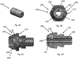
- Figures 1A-1D , 2A-2D , 3A-3D , 4A-4D , and 5A-5D illustrate example embodiments of a work member holder 100.
- the work member holder 100 may be separable from a body of a power tool.
- the work member holder 100 includes a body 110 with an outer wall 170.
- the body 110 defines a channel 120 for inserting a mandrel 150 of a work member.
- the channel 120 is defined by a circumferential inner wall 190 and extends along an x axis (X) along at least a portion of the body 110.
- a mandrel 150 when inserted into the work member holder 100 is aligned with the channel 120.
- the work member holder 100 also includes a holding member.
- the holding member applies a force on the mandrel 150 of the work member in a direction perpendicular to the length of the channel 120.
- the holding member may, for example, be disposed on at least a portion of the inner wall 190 of the channel 120, thereby enabling the mandrel 150 of the work member to be held in the channel 120.
- the holding member may include a resilient member disposed on at least a portion of the inner surface of the channel 120 that enables gripping of the mandrel 150 using friction.
- the holding member also protrudes from the inner surface of the channel 120, thereby reducing or narrowing the diameter of the channel 120 for grasping the mandrel 150 and holding it in place.
- Figures 1A-1D , 2A-2D , 3A-3D , 4A-4D , and 5A-5D illustrate a work member holder 100 that includes a holding member 130, 230, 330, 430, 530.
- the holding member 130, 230, 330, 430, 530 applies a force on the mandrel 150 of the work member in a direction perpendicular to the length of the channel 120, depicted in the figures with an "X", to hold the mandrel 150 of the work member.
- the holding member 130, 230, 330, 430, 530 grips and holds the mandrel 150 and prevents it from falling out of the work member holder 100 or power tool during free movement or, for example, if the work member holder 100 is pointed downwards, thereby allowing the work member to stay in the work member holder 100.
- the holding member 130, 230, 330, 430, 530 at least partially extends into the channel 120 to hold the mandrel 150 of the work member.
- FIGS 1A-1D illustrate a work member holder 100 in accordance with an example embodiment.
- the work member holder 100 includes a groove or depression 160 in the body 110, a holding member 130 housed at least partially within the groove 160, and a supporting means 140 for pushing the holding member 130 towards the inner wall 190 of the channel 120 and causing at least a portion of the holding member 130 to extend, or protrude, into the channel 120.
- the groove 160 extends from the inner wall 190 of the channel 120 towards the outer wall 170 of the body 110 at an incline or perpendicular to the x-axis of the channel 120, wherein the opening into the channel 120 is formed narrowly such that the holding member 130 extending into the channel 120 does not fall into the channel 120.
- the holding member 130 is circular, spherical, or cylindrical component. In a further example embodiment, the holding member 130 is a steel ball or sphere and the mandrel 150 is held in place by friction.
- the supporting means 140 can be an elastic ring.
- the elastic ring can be an O-ring.
- the supporting means 140 may also be a spring, for example a spring clip that provides a spring force to hold the mandrel 150 in place.
- the groove 160 extends from the inner wall 190 to the outer wall 170 at an incline with respect to the x-axis of the channel 120.
- the incline is at an angle of 30-110 degrees.
- the incline is preferably at an angle of 90 degrees to the x-axis.
- Figures 2A-2D and figures 3A-3D illustrate a work member holder 100 in accordance with an example embodiment.
- the holding member 230,330 extends at least partially in a circumferential direction. This is illustrated in Figures 2A-2D and Figures 3A-3D .
- the holding member 230 is circular and extends in a circumferential direction and comprises a ring 210 and a protrusion 220.
- the protrusion 220 extends inward toward a centre of the ring 210.
- the holding member 230 is disposed circumferentially around the outer wall 170 of the body 110 and the protrusion 220 protrudes or extends from the outer wall 170 into the channel 120 via a groove 160 extending from the outer wall 170 to the inner wall 190 such that the holding member 230 holds the mandrel 150 of the work member by friction.
- the holding member 230 is a resilient member that provides a spring force and retains the mandrel 150 of the work member by friction.
- the holding member 230 is an elastic ring.
- the elastic ring may be a rubber ring.
- the rubber ring may be a colour coded rubber ring for different-sized work members.
- Figures 3A-3D illustrates one example embodiment of a work member holder 100 comprising a holding member 330.
- the holding member 330 extends partially in a circumferential direction.
- the holding member 330 includes a protrusion 320 such that when the holding member 330 is disposed around the outer wall 170 of the body 110 of the work member holder 100, the protrusion 320 protrudes into the channel 120 via a groove 160 extending from the outer wall 170 to the inner wall 190 such that the holding member 330 holds the mandrel 150 of the work member by friction.
- the holding member 330 is a spring.
- the spring is a spring clip.
- Figures 4A-4D and figures 5A-5D show example embodiments of a work member holder 100 comprising a holding member 430, 530.
- the holding member 430, 530 extends in a direction perpendicular to the length of the channel 120.
- the holding member 430 runs perpendicular the length (X) of the channel 120 and a portion of the holding member 430 extends into the channel 120 thereby providing friction to hold the mandrel 150 in place.
- a groove 160 in the body 110 runs perpendicular to the length (X) of the channel 120, the groove 160 extending from the inner wall 190 of the channel to or towards the outer wall 170 of the body 110.
- the groove 160 runs diametrically across from a first end 440 of the body 110 to a second end 450 of the body 110 in a direction perpendicular to the length (X) of the channel 120.
- the holding member 430 is housed within the groove 160 and partially extends into the channel 120 to hold the mandrel 150 of the work member in the channel 120.
- the holding member 430 may be cylindrical but can also be any other shape.
- the holding member 430 comprises rubber.
- the holding member 430 comprises soft rubber in a cylindrical shape.
- Figures 5A-5D show yet another example embodiment of a work member holder 100.
- the holding member 530 extends in a direction perpendicular to the length (X) of the channel 120.
- the groove 160 runs from a first end 440 of the body 110 to a second end 450 of the body 110 in a direction perpendicular to the length (X) of the channel 120.
- the holding member 530 is housed in the groove 160 and protrudes partially into the channel 120 to hold the mandrel 150 of the work member.
- the holding member 530 is a spring.
- the holding member 530 is a spring clip.
- Example embodiments are also directed to a power tool that includes a work member holder.
- a power tool that includes the work member holder 100 as described previously.
- the power tool is a rivet gun and the work member holder is a rivet holder.
- the work member holder 100 of the invention advantageously allows for unfettered and unrestricted movement of the work member holder 100, or power tool including the same, by a user without having the need to confine their movements to prevent a work member from falling out of the work member holder 100 or power tool. This allows the user to focus on the task at hand without being concerned with mobility, thereby maximising efficiency and end user experience.
Landscapes
- Engineering & Computer Science (AREA)
- Mechanical Engineering (AREA)
- Clamps And Clips (AREA)
- Insertion Pins And Rivets (AREA)
- Portable Power Tools In General (AREA)
Applications Claiming Priority (1)
| Application Number | Priority Date | Filing Date | Title |
|---|---|---|---|
| HK19133746.8A HK30046301A2 (en) | 2019-12-17 | Work member holder |
Publications (3)
| Publication Number | Publication Date |
|---|---|
| EP3838438A1 true EP3838438A1 (de) | 2021-06-23 |
| EP3838438C0 EP3838438C0 (de) | 2023-07-12 |
| EP3838438B1 EP3838438B1 (de) | 2023-07-12 |
Family
ID=73726615
Family Applications (1)
| Application Number | Title | Priority Date | Filing Date |
|---|---|---|---|
| EP20211825.3A Active EP3838438B1 (de) | 2019-12-17 | 2020-12-04 | Niethalter |
Country Status (2)
| Country | Link |
|---|---|
| EP (1) | EP3838438B1 (de) |
| CN (1) | CN214488716U (de) |
Cited By (1)
| Publication number | Priority date | Publication date | Assignee | Title |
|---|---|---|---|---|
| EP4230328A1 (de) * | 2022-02-22 | 2023-08-23 | Black & Decker, Inc. | Blindnietsetzgerät |
Citations (7)
| Publication number | Priority date | Publication date | Assignee | Title |
|---|---|---|---|---|
| US5347892A (en) * | 1993-03-11 | 1994-09-20 | Moetteli John B | Socket retainer for thin-wall drive member |
| EP1123172A1 (de) * | 1998-06-26 | 2001-08-16 | Black & Decker Inc. | Schnellverschluss werkzeughaltereinsatz |
| EP1541266A2 (de) * | 2003-12-12 | 2005-06-15 | Collomix Rühr-und Mischgeräte GmbH | Rührwerkzeugaufnahme an einer Abtriebswelle eines Rührgerätes |
| DE102011001198A1 (de) * | 2011-03-10 | 2012-09-13 | Hs-Technik Gmbh | Nietgerät sowie Verfahren zum Vernieten eines Werkstückes |
| EP2502686A1 (de) * | 2011-03-23 | 2012-09-26 | Newfrey LLC | Blindnietbefestigungsvorrichtung |
| DE102012019177A1 (de) * | 2012-09-27 | 2014-03-27 | Gesipa Blindniettechnik Gmbh | Blindniet-Setzeinrichtung |
| EP2837468A2 (de) * | 2013-08-15 | 2015-02-18 | Black & Decker Inc. | Bithalter mit beweglicher Magnethülse |
-
2020
- 2020-12-04 CN CN202022897058.4U patent/CN214488716U/zh active Active
- 2020-12-04 EP EP20211825.3A patent/EP3838438B1/de active Active
Patent Citations (7)
| Publication number | Priority date | Publication date | Assignee | Title |
|---|---|---|---|---|
| US5347892A (en) * | 1993-03-11 | 1994-09-20 | Moetteli John B | Socket retainer for thin-wall drive member |
| EP1123172A1 (de) * | 1998-06-26 | 2001-08-16 | Black & Decker Inc. | Schnellverschluss werkzeughaltereinsatz |
| EP1541266A2 (de) * | 2003-12-12 | 2005-06-15 | Collomix Rühr-und Mischgeräte GmbH | Rührwerkzeugaufnahme an einer Abtriebswelle eines Rührgerätes |
| DE102011001198A1 (de) * | 2011-03-10 | 2012-09-13 | Hs-Technik Gmbh | Nietgerät sowie Verfahren zum Vernieten eines Werkstückes |
| EP2502686A1 (de) * | 2011-03-23 | 2012-09-26 | Newfrey LLC | Blindnietbefestigungsvorrichtung |
| DE102012019177A1 (de) * | 2012-09-27 | 2014-03-27 | Gesipa Blindniettechnik Gmbh | Blindniet-Setzeinrichtung |
| EP2837468A2 (de) * | 2013-08-15 | 2015-02-18 | Black & Decker Inc. | Bithalter mit beweglicher Magnethülse |
Cited By (1)
| Publication number | Priority date | Publication date | Assignee | Title |
|---|---|---|---|---|
| EP4230328A1 (de) * | 2022-02-22 | 2023-08-23 | Black & Decker, Inc. | Blindnietsetzgerät |
Also Published As
| Publication number | Publication date |
|---|---|
| EP3838438C0 (de) | 2023-07-12 |
| CN214488716U (zh) | 2021-10-26 |
| EP3838438B1 (de) | 2023-07-12 |
Similar Documents
| Publication | Publication Date | Title |
|---|---|---|
| US4848197A (en) | Multiple bit handtool | |
| US7318609B2 (en) | Chuck and tube joint | |
| US7082864B1 (en) | Tool with protective sheath | |
| US20060049587A1 (en) | Tool connector | |
| JPH02124274A (ja) | コードレスのポータブル電動スクリュウドライバ | |
| US10449663B2 (en) | Ergonomic handle device for holding tools | |
| US20180343991A1 (en) | Tool Holder | |
| EP3115155B1 (de) | Bithalter und kombination von werkzeug-bit und bithalter | |
| US3633640A (en) | Tool having retractable and removable centering sleeve | |
| US20150102567A1 (en) | Tool joint | |
| US20210229248A1 (en) | Attachment-type aligning device and electric power tool | |
| US20150005080A1 (en) | Universal joint structure for a tool | |
| EP3838438A1 (de) | Halter für arbeitselement | |
| US10052696B2 (en) | Drill chuck assembly | |
| US20040020331A1 (en) | Wrench having a telescopic handle | |
| US7153070B1 (en) | Drill bit guide for a hand-held drill | |
| US2893769A (en) | Socket and rod coupling | |
| US11464324B2 (en) | Paint brush holder | |
| US5426858A (en) | Combination center punch and prick punch | |
| US20170291289A1 (en) | Connecting rod for an impact member of an impact tool | |
| US20140327214A1 (en) | Instrument holder for a plotter | |
| US20080179840A1 (en) | Chuck device for a hand tool | |
| US20030110900A1 (en) | Gripping device for safely holding nails | |
| CN121756289A (zh) | 轴承座圈和密封件传动器手柄 | |
| US2862745A (en) | Socket and rod coupling |
Legal Events
| Date | Code | Title | Description |
|---|---|---|---|
| PUAI | Public reference made under article 153(3) epc to a published international application that has entered the european phase |
Free format text: ORIGINAL CODE: 0009012 |
|
| STAA | Information on the status of an ep patent application or granted ep patent |
Free format text: STATUS: THE APPLICATION HAS BEEN PUBLISHED |
|
| AK | Designated contracting states |
Kind code of ref document: A1 Designated state(s): AL AT BE BG CH CY CZ DE DK EE ES FI FR GB GR HR HU IE IS IT LI LT LU LV MC MK MT NL NO PL PT RO RS SE SI SK SM TR |
|
| STAA | Information on the status of an ep patent application or granted ep patent |
Free format text: STATUS: REQUEST FOR EXAMINATION WAS MADE |
|
| 17P | Request for examination filed |
Effective date: 20211013 |
|
| RBV | Designated contracting states (corrected) |
Designated state(s): AL AT BE BG CH CY CZ DE DK EE ES FI FR GB GR HR HU IE IS IT LI LT LU LV MC MK MT NL NO PL PT RO RS SE SI SK SM TR |
|
| STAA | Information on the status of an ep patent application or granted ep patent |
Free format text: STATUS: EXAMINATION IS IN PROGRESS |
|
| 17Q | First examination report despatched |
Effective date: 20220527 |
|
| GRAP | Despatch of communication of intention to grant a patent |
Free format text: ORIGINAL CODE: EPIDOSNIGR1 |
|
| STAA | Information on the status of an ep patent application or granted ep patent |
Free format text: STATUS: GRANT OF PATENT IS INTENDED |
|
| INTG | Intention to grant announced |
Effective date: 20230228 |
|
| GRAS | Grant fee paid |
Free format text: ORIGINAL CODE: EPIDOSNIGR3 |
|
| GRAA | (expected) grant |
Free format text: ORIGINAL CODE: 0009210 |
|
| STAA | Information on the status of an ep patent application or granted ep patent |
Free format text: STATUS: THE PATENT HAS BEEN GRANTED |
|
| AK | Designated contracting states |
Kind code of ref document: B1 Designated state(s): AL AT BE BG CH CY CZ DE DK EE ES FI FR GB GR HR HU IE IS IT LI LT LU LV MC MK MT NL NO PL PT RO RS SE SI SK SM TR |
|
| REG | Reference to a national code |
Ref country code: CH Ref legal event code: EP |
|
| REG | Reference to a national code |
Ref country code: IE Ref legal event code: FG4D |
|
| REG | Reference to a national code |
Ref country code: DE Ref legal event code: R096 Ref document number: 602020013620 Country of ref document: DE |
|
| U01 | Request for unitary effect filed |
Effective date: 20230801 |
|
| U07 | Unitary effect registered |
Designated state(s): AT BE BG DE DK EE FI FR IT LT LU LV MT NL PT SE SI Effective date: 20230804 |
|
| REG | Reference to a national code |
Ref country code: LT Ref legal event code: MG9D |
|
| PG25 | Lapsed in a contracting state [announced via postgrant information from national office to epo] |
Ref country code: GR Free format text: LAPSE BECAUSE OF FAILURE TO SUBMIT A TRANSLATION OF THE DESCRIPTION OR TO PAY THE FEE WITHIN THE PRESCRIBED TIME-LIMIT Effective date: 20231013 |
|
| PG25 | Lapsed in a contracting state [announced via postgrant information from national office to epo] |
Ref country code: ES Free format text: LAPSE BECAUSE OF FAILURE TO SUBMIT A TRANSLATION OF THE DESCRIPTION OR TO PAY THE FEE WITHIN THE PRESCRIBED TIME-LIMIT Effective date: 20230712 |
|
| PG25 | Lapsed in a contracting state [announced via postgrant information from national office to epo] |
Ref country code: IS Free format text: LAPSE BECAUSE OF FAILURE TO SUBMIT A TRANSLATION OF THE DESCRIPTION OR TO PAY THE FEE WITHIN THE PRESCRIBED TIME-LIMIT Effective date: 20231112 |
|
| PG25 | Lapsed in a contracting state [announced via postgrant information from national office to epo] |
Ref country code: RS Free format text: LAPSE BECAUSE OF FAILURE TO SUBMIT A TRANSLATION OF THE DESCRIPTION OR TO PAY THE FEE WITHIN THE PRESCRIBED TIME-LIMIT Effective date: 20230712 Ref country code: NO Free format text: LAPSE BECAUSE OF FAILURE TO SUBMIT A TRANSLATION OF THE DESCRIPTION OR TO PAY THE FEE WITHIN THE PRESCRIBED TIME-LIMIT Effective date: 20231012 Ref country code: IS Free format text: LAPSE BECAUSE OF FAILURE TO SUBMIT A TRANSLATION OF THE DESCRIPTION OR TO PAY THE FEE WITHIN THE PRESCRIBED TIME-LIMIT Effective date: 20231112 Ref country code: HR Free format text: LAPSE BECAUSE OF FAILURE TO SUBMIT A TRANSLATION OF THE DESCRIPTION OR TO PAY THE FEE WITHIN THE PRESCRIBED TIME-LIMIT Effective date: 20230712 Ref country code: GR Free format text: LAPSE BECAUSE OF FAILURE TO SUBMIT A TRANSLATION OF THE DESCRIPTION OR TO PAY THE FEE WITHIN THE PRESCRIBED TIME-LIMIT Effective date: 20231013 Ref country code: ES Free format text: LAPSE BECAUSE OF FAILURE TO SUBMIT A TRANSLATION OF THE DESCRIPTION OR TO PAY THE FEE WITHIN THE PRESCRIBED TIME-LIMIT Effective date: 20230712 |
|
| U20 | Renewal fee for the european patent with unitary effect paid |
Year of fee payment: 4 Effective date: 20231227 |
|
| PG25 | Lapsed in a contracting state [announced via postgrant information from national office to epo] |
Ref country code: PL Free format text: LAPSE BECAUSE OF FAILURE TO SUBMIT A TRANSLATION OF THE DESCRIPTION OR TO PAY THE FEE WITHIN THE PRESCRIBED TIME-LIMIT Effective date: 20230712 |
|
| REG | Reference to a national code |
Ref country code: DE Ref legal event code: R097 Ref document number: 602020013620 Country of ref document: DE |
|
| PG25 | Lapsed in a contracting state [announced via postgrant information from national office to epo] |
Ref country code: SM Free format text: LAPSE BECAUSE OF FAILURE TO SUBMIT A TRANSLATION OF THE DESCRIPTION OR TO PAY THE FEE WITHIN THE PRESCRIBED TIME-LIMIT Effective date: 20230712 Ref country code: RO Free format text: LAPSE BECAUSE OF FAILURE TO SUBMIT A TRANSLATION OF THE DESCRIPTION OR TO PAY THE FEE WITHIN THE PRESCRIBED TIME-LIMIT Effective date: 20230712 Ref country code: CZ Free format text: LAPSE BECAUSE OF FAILURE TO SUBMIT A TRANSLATION OF THE DESCRIPTION OR TO PAY THE FEE WITHIN THE PRESCRIBED TIME-LIMIT Effective date: 20230712 Ref country code: SK Free format text: LAPSE BECAUSE OF FAILURE TO SUBMIT A TRANSLATION OF THE DESCRIPTION OR TO PAY THE FEE WITHIN THE PRESCRIBED TIME-LIMIT Effective date: 20230712 |
|
| PLBE | No opposition filed within time limit |
Free format text: ORIGINAL CODE: 0009261 |
|
| STAA | Information on the status of an ep patent application or granted ep patent |
Free format text: STATUS: NO OPPOSITION FILED WITHIN TIME LIMIT |
|
| 26N | No opposition filed |
Effective date: 20240415 |
|
| REG | Reference to a national code |
Ref country code: CH Ref legal event code: PL |
|
| PG25 | Lapsed in a contracting state [announced via postgrant information from national office to epo] |
Ref country code: MC Free format text: LAPSE BECAUSE OF FAILURE TO SUBMIT A TRANSLATION OF THE DESCRIPTION OR TO PAY THE FEE WITHIN THE PRESCRIBED TIME-LIMIT Effective date: 20230712 |
|
| PG25 | Lapsed in a contracting state [announced via postgrant information from national office to epo] |
Ref country code: MC Free format text: LAPSE BECAUSE OF FAILURE TO SUBMIT A TRANSLATION OF THE DESCRIPTION OR TO PAY THE FEE WITHIN THE PRESCRIBED TIME-LIMIT Effective date: 20230712 |
|
| REG | Reference to a national code |
Ref country code: IE Ref legal event code: MM4A |
|
| PG25 | Lapsed in a contracting state [announced via postgrant information from national office to epo] |
Ref country code: IE Free format text: LAPSE BECAUSE OF NON-PAYMENT OF DUE FEES Effective date: 20231204 |
|
| PG25 | Lapsed in a contracting state [announced via postgrant information from national office to epo] |
Ref country code: CH Free format text: LAPSE BECAUSE OF NON-PAYMENT OF DUE FEES Effective date: 20231231 |
|
| PG25 | Lapsed in a contracting state [announced via postgrant information from national office to epo] |
Ref country code: IE Free format text: LAPSE BECAUSE OF NON-PAYMENT OF DUE FEES Effective date: 20231204 Ref country code: CH Free format text: LAPSE BECAUSE OF NON-PAYMENT OF DUE FEES Effective date: 20231231 |
|
| U20 | Renewal fee for the european patent with unitary effect paid |
Year of fee payment: 5 Effective date: 20241227 |
|
| PG25 | Lapsed in a contracting state [announced via postgrant information from national office to epo] |
Ref country code: CY Free format text: LAPSE BECAUSE OF FAILURE TO SUBMIT A TRANSLATION OF THE DESCRIPTION OR TO PAY THE FEE WITHIN THE PRESCRIBED TIME-LIMIT; INVALID AB INITIO Effective date: 20201204 |
|
| PG25 | Lapsed in a contracting state [announced via postgrant information from national office to epo] |
Ref country code: HU Free format text: LAPSE BECAUSE OF FAILURE TO SUBMIT A TRANSLATION OF THE DESCRIPTION OR TO PAY THE FEE WITHIN THE PRESCRIBED TIME-LIMIT; INVALID AB INITIO Effective date: 20201204 |
|
| PG25 | Lapsed in a contracting state [announced via postgrant information from national office to epo] |
Ref country code: TR Free format text: LAPSE BECAUSE OF FAILURE TO SUBMIT A TRANSLATION OF THE DESCRIPTION OR TO PAY THE FEE WITHIN THE PRESCRIBED TIME-LIMIT Effective date: 20230712 |
|
| PGFP | Annual fee paid to national office [announced via postgrant information from national office to epo] |
Ref country code: GB Payment date: 20251229 Year of fee payment: 6 |
|
| U20 | Renewal fee for the european patent with unitary effect paid |
Year of fee payment: 6 Effective date: 20251229 |