EP3838461B1 - Scheibenschneidmaschine mit kühlvorrichtung - Google Patents
Scheibenschneidmaschine mit kühlvorrichtung Download PDFInfo
- Publication number
- EP3838461B1 EP3838461B1 EP20000410.9A EP20000410A EP3838461B1 EP 3838461 B1 EP3838461 B1 EP 3838461B1 EP 20000410 A EP20000410 A EP 20000410A EP 3838461 B1 EP3838461 B1 EP 3838461B1
- Authority
- EP
- European Patent Office
- Prior art keywords
- disc
- cannula
- nozzle
- coolant
- cutter
- Prior art date
- Legal status (The legal status is an assumption and is not a legal conclusion. Google has not performed a legal analysis and makes no representation as to the accuracy of the status listed.)
- Active
Links
Images
Classifications
-
- B—PERFORMING OPERATIONS; TRANSPORTING
- B26—HAND CUTTING TOOLS; CUTTING; SEVERING
- B26D—CUTTING; DETAILS COMMON TO MACHINES FOR PERFORATING, PUNCHING, CUTTING-OUT, STAMPING-OUT OR SEVERING
- B26D7/00—Details of apparatus for cutting, cutting-out, stamping-out, punching, perforating, or severing by means other than cutting
- B26D7/08—Means for treating work or cutting member to facilitate cutting
-
- B—PERFORMING OPERATIONS; TRANSPORTING
- B23—MACHINE TOOLS; METAL-WORKING NOT OTHERWISE PROVIDED FOR
- B23D—PLANING; SLOTTING; SHEARING; BROACHING; SAWING; FILING; SCRAPING; LIKE OPERATIONS FOR WORKING METAL BY REMOVING MATERIAL, NOT OTHERWISE PROVIDED FOR
- B23D59/00—Accessories specially designed for sawing machines or sawing devices
- B23D59/02—Devices for lubricating or cooling circular saw blades
- B23D59/025—Devices for lubricating or cooling circular saw blades the lubricating or cooling medium being applied through the mounting means of the tool, e.g. the tool spindle or hub
-
- B—PERFORMING OPERATIONS; TRANSPORTING
- B23—MACHINE TOOLS; METAL-WORKING NOT OTHERWISE PROVIDED FOR
- B23Q—DETAILS, COMPONENTS, OR ACCESSORIES FOR MACHINE TOOLS, e.g. ARRANGEMENTS FOR COPYING OR CONTROLLING; MACHINE TOOLS IN GENERAL CHARACTERISED BY THE CONSTRUCTION OF PARTICULAR DETAILS OR COMPONENTS; COMBINATIONS OR ASSOCIATIONS OF METAL-WORKING MACHINES, NOT DIRECTED TO A PARTICULAR RESULT
- B23Q11/00—Accessories fitted to machine tools for keeping tools or parts of the machine in good working condition or for cooling work; Safety devices specially combined with or arranged in, or specially adapted for use in connection with, machine tools
- B23Q11/10—Arrangements for cooling or lubricating tools or work
-
- B—PERFORMING OPERATIONS; TRANSPORTING
- B23—MACHINE TOOLS; METAL-WORKING NOT OTHERWISE PROVIDED FOR
- B23D—PLANING; SLOTTING; SHEARING; BROACHING; SAWING; FILING; SCRAPING; LIKE OPERATIONS FOR WORKING METAL BY REMOVING MATERIAL, NOT OTHERWISE PROVIDED FOR
- B23D59/00—Accessories specially designed for sawing machines or sawing devices
- B23D59/02—Devices for lubricating or cooling circular saw blades
-
- B—PERFORMING OPERATIONS; TRANSPORTING
- B26—HAND CUTTING TOOLS; CUTTING; SEVERING
- B26B—HAND-HELD CUTTING TOOLS NOT OTHERWISE PROVIDED FOR
- B26B25/00—Hand cutting tools involving disc blades, e.g. motor-driven
- B26B25/005—Manually operated, e.g. pizza cutters
-
- B—PERFORMING OPERATIONS; TRANSPORTING
- B26—HAND CUTTING TOOLS; CUTTING; SEVERING
- B26B—HAND-HELD CUTTING TOOLS NOT OTHERWISE PROVIDED FOR
- B26B29/00—Guards or sheaths or guides for hand cutting tools; Arrangements for guiding hand cutting tools
-
- B—PERFORMING OPERATIONS; TRANSPORTING
- B28—WORKING CEMENT, CLAY, OR STONE
- B28D—WORKING STONE OR STONE-LIKE MATERIALS
- B28D7/00—Accessories specially adapted for use with machines or devices of the preceding groups
- B28D7/02—Accessories specially adapted for use with machines or devices of the preceding groups for removing or laying dust, e.g. by spraying liquids; for cooling work
Definitions
- This invention relates to a disc cutter as per the preamble of appended claim 1.
- Disc cutters that have a device for cooling the disc, in order to prevent the deterioration thereof due to overheating and to extend the useful life of the disc, are currently known on the market.
- Document US385666 describes a machine provided with a protective cover for a cutter disc and with two tubes for supplying coolant to the disc, connected by means of a key to a single feed tube, and which enable the coolant to be supplied on the upper half of the cutter disc.
- Invention patent ES 2 630 366 B1 of the same holder of the present invention, describes a protective cover with cooling for cutter discs.
- Said protective cover defines a cavity, generally semi-cylindrical, which comprises fastening means inside a tube and a nozzle for supplying coolant at different heights on the upper half of the cutter disc.
- This document is a family member of EP3208022 . Both documents disclose a disc cutter as per the preamble of appended claim 1.
- Said protective cover with cooling for cutter discs uses a single tube for supplying coolant, which is an advantage over patent US385666 by simplifying the construction thereof; further exhibiting the particularity that the lateral walls of the cover comprise fins internally, the purpose of which is to redirect the coolant that is thrown tangentially against the perimeter wall of the cover due to the rapid rotational movement of the disc towards the lateral faces of the disc.
- This background ES 2 630 366 B1 provides clear advantages of use with respect to the aforementioned background US385666 , although the cooling capacity of the disc is also limited by the projection of coolant on the upper area of the disc, either by means of the nozzle or by means of the fins defined on the lateral walls of the cover.
- the technical problem that arises is the development of a cooling device that enables the cooling capacity of the disc to be increased, applying the coolant in the area of the disc where the heating thereof originates, and that does not require fins to be defined on the lateral walls of the protective cover of the disc for redirecting the coolant projected tangentially by the rotational movement of the disc towards the disc.
- the disc cutter comprising a cooling device, object of the present invention, is of the type described in the preamble of claim 1 and provided with a protective cover that covers approximately the upper half of the disc and which comprises: a tube for supplying coolant and a nozzle that pours the coolant on the disc.
- An objective of the invention is to cool the disc by means of tangential pouring of the coolant on a lower sector of the disc and specifically in the area where the heating thereof takes place, i.e., in the disc contact and penetration area in the part to be cut.
- Another objective of the invention is to ensure that the nozzle maintains a constant separation with respect to the periphery of the disc when said nozzle moves away from the cover, towards the lower cantilevered area, to approach the cutting area of the part.
- the means for attaching the cannula at different points of the path thereof comprise a fastening clip attached to said cannula and it passes to the outside of the cannula through a groove that affects at least one section of the curved guide and the outer surface of the cover.
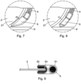
- the cover exhibits a series of reliefs along said groove for coupling the fastening clip and holding the cannula at different points of the path thereof.
- the arrangement of said clip on the cover enables the user to comfortably and easily adjust the position of the nozzle to bring it closer to the cutting area, even during the cutting operation, without approaching the disc and therefore without risk of accidents.
- An additional advantage derived from the ease and comfort of actuation of these attachment means, is that the cannula can be initially arranged in the highest position so that the nozzle does not pose a visual obstruction when the cutting begins and then bring it closer to the cutting area to improve disc cooling.
- the means for attaching the cannula in different positions can be of any other suitable type and equivalent to those mentioned above.
- the pouring of coolant is carried out in the indicated area and simultaneously on the two opposite faces and on the periphery of the perimeter portion of the disc, thus ensuring a uniform and highly efficient cooling of the disc.
- a nozzle that exhibits a specific configuration has been designed, said nozzle comprising an upper mouth, coupled to the tube for supplying coolant, a visor for pouring coolant facing the inside of the disc and which has a cut shaping a passage area of a perimeter portion of the disc at the end thereof, said visor simultaneously pouring coolant on the two opposite faces and on the periphery of said perimeter portion of the disc.
- the disc is cooled specifically in the area where the heating of the disc is produced, i.e., in the disc contact and penetration area in the part to be cut and, on the other hand, that the coolant causes uniform cooling of said contact area by being simultaneously applied on the two opposite faces and on the peripheral edge of said area of the disc.
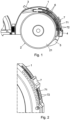
- Figure 1 shows a disc cutter provided with a protective cover (1) which covers approximately the upper half of the cutting disc (2).
- the cooling device comprises a tube (3) for supplying coolant, a cannula (4) and a nozzle (5) that pours the coolant on the periphery of the disc (2);
- the cannula (4) is mounted and capable of longitudinal movement in a curved, tubular guide (6), which has a radius of curvature slightly greater than the cutter disc and which is attached inside the cover (1) and concentric with the periphery of the disc (2).
- the cannula (4) is made of a semi-rigid material and has a curvature according to the curved guide, so that when said cannula moves towards the lower area, the end carrying the nozzle protrudes in a cantilever below the cover, ensuring that the nozzle describes a path parallel to the contour of the disc (2).
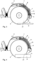
- the device comprises means for attaching the cannula (4) at different points of the path thereof along the curved guide (6) and consequently for attaching the nozzle (5) on different points of a lower sector (21) of the periphery of the disc.
- the means for attaching the cannula (4) comprise a fastening clip (7) attached to said cannula (4) and which protrudes through a groove (71) that affects at least one section of the curved guide (6) and of the cover (1).
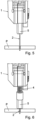
- the means for attaching the cannula (4) enable the nozzle (5) to be located at different heights, and in a position facing the disc (2) contact and penetration area in the part (P) to be cut, ensuring proper cooling.
- the means for attaching the cannula enable the nozzle (5) to be located in an upper position, close to the cover, at the beginning of the cutting of a part, so that said nozzle does not pose an obstruction and enables the cutting area to be visualised; and in a lower position during the cutting of said part, ensuring the effective cooling of the disc cutting area.
- the nozzle (5) is interchangeable and can exhibit different configurations, suitable for projecting the coolant tangentially to the rotation of the disc, and always in the disc cutting area.
- the nozzle shown in Figure 5 has a specific configuration for projecting the coolant tangentially on the disc (2) cutting area.
- Said nozzle (5) comprises an upper mouth (51) for coupling thereof to the cannula (4) for supplying coolant, said nozzle (5) extending towards the lower area into a visor (52) for pouring coolant, facing the inside of the disc (2) and which has a cut (53) shaping a passage area of a perimeter portion of the disc (2) at the end thereof, said visor (52) simultaneously pouring coolant on the two opposite faces and on the periphery of said perimeter portion of the disc (2).
Landscapes
- Engineering & Computer Science (AREA)
- Mechanical Engineering (AREA)
- Life Sciences & Earth Sciences (AREA)
- Forests & Forestry (AREA)
- Processing Of Stones Or Stones Resemblance Materials (AREA)
- Auxiliary Devices For Machine Tools (AREA)
Claims (4)
- Scheibenschneider, umfassend eine Schneidscheibe (2), eine Schutzabdeckung (1), die etwa die obere Hälfte der Scheibe (2) abdeckt, und eine Kühlvorrichtung, umfassend: ein Rohr (3) zum Zuführen von Kühlmittel, eine Düse (5), die das Kühlmittel auf die Scheibe (2) gießt, und eine gekrümmte, röhrenförmige Führung (6) mit einem etwas größeren Krümmungsradius als die Schneidscheibe (2), die innerhalb der Abdeckung (1) befestigt und mit dem Umfang der Scheibe (2) konzentrisch ist;
dadurch gekennzeichnet, dass die Kühlvorrichtung ferner Folgendes umfasst:- eine gekrümmte Kanüle (4) aus halbstarrem Material, die innerhalb der gekrümmten Führung (6) montiert ist, die zu einer Längsbewegung zwischen zwei Endpositionen fähig ist und mit einem oberen Ende, das mit dem Rohr (3) zum Zuführen von Kühlmittel verbunden ist, und einem unteren Ende, das unter der Abdeckung (1) hervorsteht und an dem die Düse (5) angekoppelt ist, versehen ist,- Mittel zum Anbringen der Kanüle (4) an verschiedenen Stellen ihres Weges; so dass sich die Düse (5) während der Bewegung der Kanüle (4) über einen unteren Sektor (21) des Umfangs der Scheibe (2) bewegt, und während des Schneidens von Teilen (P) unterschiedlicher Dicke die Düse (5) sich in unterschiedlichen Höhen und gegenüber der Kontakt- und Eindringfläche der Scheibe (2) in dem zu schneidenden Teil (P) befindet. - Scheibenschneider nach Anspruch 1, dadurch gekennzeichnet, dass die Mittel zum Anbringen der Kanüle (4) an verschiedenen Stellen ihres Weges eine Befestigungsklammer (7) umfassen, die an der Kanüle (4) angebracht ist und die durch eine Nut (71) vorsteht und die mindestens einen Abschnitt der gekrümmten Führung (6) und der Außenfläche der Abdeckung (1) beeinflusst.
- Scheibenschneider nach Anspruch 2, dadurch gekennzeichnet, dass er eine Reihe von Aussparungen (72) entlang der Nut (71) der Abdeckung (1) umfasst, um die Befestigungsklammer (7) zu koppeln und die Kanüle (4) in verschiedenen Positionen zu halten.
- Scheibenschneider nach einem der Ansprüche 1 bis 3, dadurch gekennzeichnet, dass die Düse (5) eine obere Mündung (51) zu ihrer Verbindung mit der Kanüle (4) zum Zuführen von Kühlmittel umfasst und sich zum unteren Bereich in eine Blende (52) zum Gießen von Kühlmittel erstreckt, die der Innenseite der Scheibe (2) zugewandt ist und die einen Einschnitt (53) aufweist, der einen Durchgangsbereich eines Umfangsabschnitts der Scheibe (2) an ihrem Ende formt; wobei die Blende (52) gleichzeitig Kühlmittel auf die beiden gegenüberliegenden Flächen und auf den Umfang des Umfangsabschnitts der Scheibe (2) gießt.
Applications Claiming Priority (1)
| Application Number | Priority Date | Filing Date | Title |
|---|---|---|---|
| ES201931113A ES2834728B2 (es) | 2019-12-17 | 2019-12-17 | Dispositivo de refrigeracion para cortadoras de disco |
Publications (3)
| Publication Number | Publication Date |
|---|---|
| EP3838461A1 EP3838461A1 (de) | 2021-06-23 |
| EP3838461C0 EP3838461C0 (de) | 2023-06-07 |
| EP3838461B1 true EP3838461B1 (de) | 2023-06-07 |
Family
ID=73448764
Family Applications (1)
| Application Number | Title | Priority Date | Filing Date |
|---|---|---|---|
| EP20000410.9A Active EP3838461B1 (de) | 2019-12-17 | 2020-11-12 | Scheibenschneidmaschine mit kühlvorrichtung |
Country Status (6)
| Country | Link |
|---|---|
| US (1) | US11376756B2 (de) |
| EP (1) | EP3838461B1 (de) |
| CN (1) | CN112720050B (de) |
| CA (1) | CA3099555C (de) |
| ES (2) | ES2834728B2 (de) |
| PL (1) | PL3838461T3 (de) |
Families Citing this family (9)
| Publication number | Priority date | Publication date | Assignee | Title |
|---|---|---|---|---|
| US20220072672A1 (en) * | 2020-09-04 | 2022-03-10 | Sergey Nikolenko | Apparatus for cutting, grinding, and polishing work pieces at multiple axes |
| CN115155758B (zh) * | 2022-07-06 | 2023-09-12 | 浙江迦南科技股份有限公司 | 一种组合型破块刀盘及其使用方法 |
| CN116277264B (zh) * | 2023-01-16 | 2026-01-30 | 英德海螺型材有限责任公司 | 一种型材框用清角设备及其使用方法 |
| CN116922283B (zh) * | 2023-07-12 | 2026-01-06 | 桂林创源金刚石有限公司 | 一种三重复合磨盘及玻璃直线直边磨边机 |
| US12528174B2 (en) * | 2023-09-01 | 2026-01-20 | Hydro-Tail Llc | Universal attachable water directing device for power tools |
| CN117961787B (zh) * | 2024-03-26 | 2024-06-25 | 济南础润光电有限公司 | 一种工件圆弧面粗糙度加工设备 |
| CN118287751B (zh) * | 2024-06-06 | 2024-08-30 | 江苏金叶胶辊有限公司 | 一种胶辊铁芯自动切割装置 |
| CN119099051B (zh) * | 2024-09-05 | 2025-06-20 | 开普智能制造(常州)有限公司 | 一种混凝土用切割装置及其切割工艺 |
| CN120422119B (zh) * | 2025-07-08 | 2025-09-02 | 江苏大洋精锻有限公司 | 一种铝合金汽车零部件抛光设备 |
Family Cites Families (26)
| Publication number | Priority date | Publication date | Assignee | Title |
|---|---|---|---|---|
| US385666A (en) | 1888-07-03 | Island | ||
| US992490A (en) * | 1910-12-12 | 1911-05-16 | Henry A Fergusson | Hood for friction-saws. |
| US2163687A (en) * | 1938-01-10 | 1939-06-27 | Bucyrus Monighan Company | Cutting |
| FR1301500A (fr) * | 1960-08-19 | 1962-08-17 | Hydrol Chemical Company Ltd | Machine à meuler |
| US3661045A (en) * | 1970-09-17 | 1972-05-09 | Tyco Lab | Apparatus for stabilizing a rotary saw blade |
| US3848929A (en) * | 1973-06-14 | 1974-11-19 | Engelhard Min & Chem | Water applicator for a pavement grooving machine |
| US4153973A (en) * | 1976-01-26 | 1979-05-15 | Armour And Company | Tool for cutting materials and methods for sterilizing the same |
| ZA801174B (en) * | 1979-03-09 | 1981-02-25 | De Beers Ind Diamond | Circular saws |
| US4414783A (en) * | 1981-08-19 | 1983-11-15 | Buehler Ltd. | Coolant system for rotating blade cutter |
| US4619081A (en) * | 1985-02-28 | 1986-10-28 | General Signal Corporation | Combined nozzle with air foil |
| SE467094B (sv) * | 1989-03-30 | 1992-05-25 | Electrolux Motor Ab | Anordning vid cirkelsaag |
| JP3189577B2 (ja) * | 1993-10-29 | 2001-07-16 | 日立工機株式会社 | 電動石材カッタ |
| US5461008A (en) * | 1994-05-26 | 1995-10-24 | Delco Electronics Corporatinon | Method of preventing aluminum bond pad corrosion during dicing of integrated circuit wafers |
| DE19545416A1 (de) * | 1995-12-06 | 1997-06-12 | Stihl Maschf Andreas | Düse zur Flüssigkeitszufuhr zu einem drehenden Werkzeug |
| SE518103C2 (sv) * | 2000-12-12 | 2002-08-27 | Electrolux Abp | Vattenpump vid portabel kapmaskin |
| US7047784B2 (en) * | 2003-08-12 | 2006-05-23 | Belco Industries, Inc. | Hot cut aluminum billet saw |
| US8910552B2 (en) * | 2005-03-01 | 2014-12-16 | Blue Collar Ventures, L.L.C. | Movable saw apparatus and method |
| DE202005006371U1 (de) * | 2005-04-20 | 2006-08-31 | Dolmar Gmbh | Trennschleifgerät |
| US7987752B2 (en) * | 2008-03-18 | 2011-08-02 | Mk Diamond Products, Inc. | System and method for delivering pressurized fluid to a rotary cutting blade |
| JP2009285769A (ja) * | 2008-05-28 | 2009-12-10 | Disco Abrasive Syst Ltd | 切削装置 |
| AU2009253732B2 (en) * | 2008-05-30 | 2011-07-14 | Robert Andrew Irvine | Wet cutting saw |
| DE202011050394U1 (de) * | 2011-06-08 | 2012-09-10 | Makita Corporation | Schutzhaube für ein handhaltbares Motorarbeitsgerät |
| DE202011050396U1 (de) * | 2011-06-08 | 2012-09-10 | Makita Corporation | Zuführeinrichtung zur Bedüsung eines Werkzeugs eines handhaltbaren Motorarbeitsgerätes und ebensolches Motorarbeitsgerät |
| CN104625228A (zh) * | 2013-11-14 | 2015-05-20 | 湖州巨力铝型材有限公司 | 一种带冷却机构的铝棒切割机 |
| US10751816B2 (en) * | 2016-02-17 | 2020-08-25 | Germans Boada, S.A. | Protective cooling cover for cutter discs |
| ES2630366B1 (es) | 2016-02-17 | 2018-06-08 | Germans Boada, S.A. | Tapa de protección con refrigeración para discos de cortadoras |
-
2019
- 2019-12-17 ES ES201931113A patent/ES2834728B2/es not_active Expired - Fee Related
-
2020
- 2020-11-12 ES ES20000410T patent/ES2949685T3/es active Active
- 2020-11-12 PL PL20000410.9T patent/PL3838461T3/pl unknown
- 2020-11-12 CA CA3099555A patent/CA3099555C/en active Active
- 2020-11-12 EP EP20000410.9A patent/EP3838461B1/de active Active
- 2020-11-30 US US17/107,451 patent/US11376756B2/en not_active Expired - Fee Related
- 2020-12-03 CN CN202011395939.4A patent/CN112720050B/zh active Active
Also Published As
| Publication number | Publication date |
|---|---|
| ES2834728A1 (es) | 2021-06-18 |
| US20210252731A1 (en) | 2021-08-19 |
| CA3099555A1 (en) | 2021-06-17 |
| EP3838461C0 (de) | 2023-06-07 |
| CN112720050A (zh) | 2021-04-30 |
| ES2834728B2 (es) | 2022-06-09 |
| CA3099555C (en) | 2023-03-14 |
| EP3838461A1 (de) | 2021-06-23 |
| ES2949685T3 (es) | 2023-10-02 |
| US11376756B2 (en) | 2022-07-05 |
| CN112720050B (zh) | 2023-04-18 |
| PL3838461T3 (pl) | 2023-07-31 |
Similar Documents
| Publication | Publication Date | Title |
|---|---|---|
| US11376756B2 (en) | Cooling device for disc cutters | |
| EP3843573B1 (de) | Sicherheitshelm | |
| CN115091750B (zh) | 双喷头装置及3d打印设备 | |
| US10751816B2 (en) | Protective cooling cover for cutter discs | |
| US5859405A (en) | Cutting tool precision turning method and apparatus for a heat-treatable steel workpiece | |
| CN105312599B (zh) | 具有增强的冷却剂递送的带有切削刀片的切削组件 | |
| US6591424B1 (en) | Welder helmet with fixed and movable face shields | |
| EP3513892B1 (de) | Schneidwerkzeug | |
| EP3231541B1 (de) | Ein stirnseitig einstechender werkzeugkörper für metallzerspannung | |
| JP2008272924A (ja) | 切削インサート | |
| CN106659262A (zh) | 用于防护头盔的可移除的护罩 | |
| EP3774210B1 (de) | Haarschneideeinheit mit klingenblockierverhinderung | |
| JP4388736B2 (ja) | ケーシングに空気流入開口もしくは空気流出開口を備えた手持ち式工作機械 | |
| EP3290157B1 (de) | Winkelschleifer | |
| CN213080259U (zh) | 圆锯 | |
| EP1944086B1 (de) | Aktenvernichteranordnung | |
| US20210060811A1 (en) | Portable cutting machine | |
| US6301110B1 (en) | Electronic component cooling apparatus | |
| EP3208022B1 (de) | Schutzabdeckung mit kühlung für messerscheiben | |
| JP6219419B2 (ja) | 内部冷却付き小型デバリング及び/又はチャンファリング工具 | |
| JP4634654B2 (ja) | 合成樹脂製容器蓋 | |
| CN103358359B (zh) | 切割机 | |
| KR20240058115A (ko) | 인서트 수용 포켓과 절삭 공구를 규정하는 상부 및 하부 조를 구비한 공구 홀더 | |
| TWI289500B (en) | Mold for molding disk substrate and method for molding disk substrate | |
| WO2009030089A1 (fr) | Guide-chaîne de scie à chaîne |
Legal Events
| Date | Code | Title | Description |
|---|---|---|---|
| PUAI | Public reference made under article 153(3) epc to a published international application that has entered the european phase |
Free format text: ORIGINAL CODE: 0009012 |
|
| STAA | Information on the status of an ep patent application or granted ep patent |
Free format text: STATUS: THE APPLICATION HAS BEEN PUBLISHED |
|
| AK | Designated contracting states |
Kind code of ref document: A1 Designated state(s): AL AT BE BG CH CY CZ DE DK EE ES FI FR GB GR HR HU IE IS IT LI LT LU LV MC MK MT NL NO PL PT RO RS SE SI SK SM TR |
|
| STAA | Information on the status of an ep patent application or granted ep patent |
Free format text: STATUS: REQUEST FOR EXAMINATION WAS MADE |
|
| 17P | Request for examination filed |
Effective date: 20210915 |
|
| GRAP | Despatch of communication of intention to grant a patent |
Free format text: ORIGINAL CODE: EPIDOSNIGR1 |
|
| STAA | Information on the status of an ep patent application or granted ep patent |
Free format text: STATUS: GRANT OF PATENT IS INTENDED |
|
| INTG | Intention to grant announced |
Effective date: 20230227 |
|
| GRAS | Grant fee paid |
Free format text: ORIGINAL CODE: EPIDOSNIGR3 |
|
| GRAA | (expected) grant |
Free format text: ORIGINAL CODE: 0009210 |
|
| STAA | Information on the status of an ep patent application or granted ep patent |
Free format text: STATUS: THE PATENT HAS BEEN GRANTED |
|
| AK | Designated contracting states |
Kind code of ref document: B1 Designated state(s): AL AT BE BG CH CY CZ DE DK EE ES FI FR GB GR HR HU IE IS IT LI LT LU LV MC MK MT NL NO PL PT RO RS SE SI SK SM TR |
|
| REG | Reference to a national code |
Ref country code: GB Ref legal event code: FG4D |
|
| REG | Reference to a national code |
Ref country code: CH Ref legal event code: EP Ref country code: AT Ref legal event code: REF Ref document number: 1573497 Country of ref document: AT Kind code of ref document: T Effective date: 20230615 |
|
| REG | Reference to a national code |
Ref country code: DE Ref legal event code: R096 Ref document number: 602020011410 Country of ref document: DE |
|
| U01 | Request for unitary effect filed |
Effective date: 20230630 |
|
| U07 | Unitary effect registered |
Designated state(s): AT BE BG DE DK EE FI FR IT LT LU LV MT NL PT SE SI Effective date: 20230711 |
|
| REG | Reference to a national code |
Ref country code: LT Ref legal event code: MG9D |
|
| REG | Reference to a national code |
Ref country code: ES Ref legal event code: FG2A Ref document number: 2949685 Country of ref document: ES Kind code of ref document: T3 Effective date: 20231002 |
|
| U20 | Renewal fee for the european patent with unitary effect paid |
Year of fee payment: 4 Effective date: 20230919 |
|
| PG25 | Lapsed in a contracting state [announced via postgrant information from national office to epo] |
Ref country code: NO Free format text: LAPSE BECAUSE OF FAILURE TO SUBMIT A TRANSLATION OF THE DESCRIPTION OR TO PAY THE FEE WITHIN THE PRESCRIBED TIME-LIMIT Effective date: 20230907 |
|
| PG25 | Lapsed in a contracting state [announced via postgrant information from national office to epo] |
Ref country code: RS Free format text: LAPSE BECAUSE OF FAILURE TO SUBMIT A TRANSLATION OF THE DESCRIPTION OR TO PAY THE FEE WITHIN THE PRESCRIBED TIME-LIMIT Effective date: 20230607 Ref country code: HR Free format text: LAPSE BECAUSE OF FAILURE TO SUBMIT A TRANSLATION OF THE DESCRIPTION OR TO PAY THE FEE WITHIN THE PRESCRIBED TIME-LIMIT Effective date: 20230607 Ref country code: GR Free format text: LAPSE BECAUSE OF FAILURE TO SUBMIT A TRANSLATION OF THE DESCRIPTION OR TO PAY THE FEE WITHIN THE PRESCRIBED TIME-LIMIT Effective date: 20230908 |
|
| PG25 | Lapsed in a contracting state [announced via postgrant information from national office to epo] |
Ref country code: SK Free format text: LAPSE BECAUSE OF FAILURE TO SUBMIT A TRANSLATION OF THE DESCRIPTION OR TO PAY THE FEE WITHIN THE PRESCRIBED TIME-LIMIT Effective date: 20230607 |
|
| PG25 | Lapsed in a contracting state [announced via postgrant information from national office to epo] |
Ref country code: IS Free format text: LAPSE BECAUSE OF FAILURE TO SUBMIT A TRANSLATION OF THE DESCRIPTION OR TO PAY THE FEE WITHIN THE PRESCRIBED TIME-LIMIT Effective date: 20231007 |
|
| PG25 | Lapsed in a contracting state [announced via postgrant information from national office to epo] |
Ref country code: SM Free format text: LAPSE BECAUSE OF FAILURE TO SUBMIT A TRANSLATION OF THE DESCRIPTION OR TO PAY THE FEE WITHIN THE PRESCRIBED TIME-LIMIT Effective date: 20230607 Ref country code: SK Free format text: LAPSE BECAUSE OF FAILURE TO SUBMIT A TRANSLATION OF THE DESCRIPTION OR TO PAY THE FEE WITHIN THE PRESCRIBED TIME-LIMIT Effective date: 20230607 Ref country code: RO Free format text: LAPSE BECAUSE OF FAILURE TO SUBMIT A TRANSLATION OF THE DESCRIPTION OR TO PAY THE FEE WITHIN THE PRESCRIBED TIME-LIMIT Effective date: 20230607 Ref country code: IS Free format text: LAPSE BECAUSE OF FAILURE TO SUBMIT A TRANSLATION OF THE DESCRIPTION OR TO PAY THE FEE WITHIN THE PRESCRIBED TIME-LIMIT Effective date: 20231007 Ref country code: CZ Free format text: LAPSE BECAUSE OF FAILURE TO SUBMIT A TRANSLATION OF THE DESCRIPTION OR TO PAY THE FEE WITHIN THE PRESCRIBED TIME-LIMIT Effective date: 20230607 |
|
| REG | Reference to a national code |
Ref country code: DE Ref legal event code: R097 Ref document number: 602020011410 Country of ref document: DE |
|
| PLBE | No opposition filed within time limit |
Free format text: ORIGINAL CODE: 0009261 |
|
| STAA | Information on the status of an ep patent application or granted ep patent |
Free format text: STATUS: NO OPPOSITION FILED WITHIN TIME LIMIT |
|
| 26N | No opposition filed |
Effective date: 20240308 |
|
| REG | Reference to a national code |
Ref country code: CH Ref legal event code: PL |
|
| PG25 | Lapsed in a contracting state [announced via postgrant information from national office to epo] |
Ref country code: MC Free format text: LAPSE BECAUSE OF FAILURE TO SUBMIT A TRANSLATION OF THE DESCRIPTION OR TO PAY THE FEE WITHIN THE PRESCRIBED TIME-LIMIT Effective date: 20230607 |
|
| PG25 | Lapsed in a contracting state [announced via postgrant information from national office to epo] |
Ref country code: CH Free format text: LAPSE BECAUSE OF NON-PAYMENT OF DUE FEES Effective date: 20231130 |
|
| PG25 | Lapsed in a contracting state [announced via postgrant information from national office to epo] |
Ref country code: MC Free format text: LAPSE BECAUSE OF FAILURE TO SUBMIT A TRANSLATION OF THE DESCRIPTION OR TO PAY THE FEE WITHIN THE PRESCRIBED TIME-LIMIT Effective date: 20230607 Ref country code: CH Free format text: LAPSE BECAUSE OF NON-PAYMENT OF DUE FEES Effective date: 20231130 |
|
| U20 | Renewal fee for the european patent with unitary effect paid |
Year of fee payment: 5 Effective date: 20240903 |
|
| PG25 | Lapsed in a contracting state [announced via postgrant information from national office to epo] |
Ref country code: CY Free format text: LAPSE BECAUSE OF FAILURE TO SUBMIT A TRANSLATION OF THE DESCRIPTION OR TO PAY THE FEE WITHIN THE PRESCRIBED TIME-LIMIT; INVALID AB INITIO Effective date: 20201112 |
|
| PG25 | Lapsed in a contracting state [announced via postgrant information from national office to epo] |
Ref country code: HU Free format text: LAPSE BECAUSE OF FAILURE TO SUBMIT A TRANSLATION OF THE DESCRIPTION OR TO PAY THE FEE WITHIN THE PRESCRIBED TIME-LIMIT; INVALID AB INITIO Effective date: 20201112 |
|
| U20 | Renewal fee for the european patent with unitary effect paid |
Year of fee payment: 6 Effective date: 20250918 |
|
| PG25 | Lapsed in a contracting state [announced via postgrant information from national office to epo] |
Ref country code: TR Free format text: LAPSE BECAUSE OF FAILURE TO SUBMIT A TRANSLATION OF THE DESCRIPTION OR TO PAY THE FEE WITHIN THE PRESCRIBED TIME-LIMIT Effective date: 20230607 |
|
| PGFP | Annual fee paid to national office [announced via postgrant information from national office to epo] |
Ref country code: GB Payment date: 20251127 Year of fee payment: 6 |
|
| PGFP | Annual fee paid to national office [announced via postgrant information from national office to epo] |
Ref country code: IE Payment date: 20251127 Year of fee payment: 6 |
|
| PGFP | Annual fee paid to national office [announced via postgrant information from national office to epo] |
Ref country code: PL Payment date: 20251021 Year of fee payment: 6 |
|
| PGFP | Annual fee paid to national office [announced via postgrant information from national office to epo] |
Ref country code: ES Payment date: 20251202 Year of fee payment: 6 |
|
| U1H | Name or address of the proprietor changed after the registration of the unitary effect |
Owner name: RUBI TOOLS GROUP, S.A.; ES |
|
| REG | Reference to a national code |
Ref country code: ES Ref legal event code: PC2A Owner name: RUBI TOOLS GROUP, S.A. Effective date: 20260625 |