EP3838470A1 - Détection de pièces étrangères et de scories sur une table de travail - Google Patents
Détection de pièces étrangères et de scories sur une table de travail Download PDFInfo
- Publication number
- EP3838470A1 EP3838470A1 EP19216784.9A EP19216784A EP3838470A1 EP 3838470 A1 EP3838470 A1 EP 3838470A1 EP 19216784 A EP19216784 A EP 19216784A EP 3838470 A1 EP3838470 A1 EP 3838470A1
- Authority
- EP
- European Patent Office
- Prior art keywords
- sensor
- distance
- deposits
- support elements
- work table
- Prior art date
- Legal status (The legal status is an assumption and is not a legal conclusion. Google has not performed a legal analysis and makes no representation as to the accuracy of the status listed.)
- Withdrawn
Links
Images



Classifications
-
- B—PERFORMING OPERATIONS; TRANSPORTING
- B23—MACHINE TOOLS; METAL-WORKING NOT OTHERWISE PROVIDED FOR
- B23K—SOLDERING OR UNSOLDERING; WELDING; CLADDING OR PLATING BY SOLDERING OR WELDING; CUTTING BY APPLYING HEAT LOCALLY, e.g. FLAME CUTTING; WORKING BY LASER BEAM
- B23K26/00—Working by laser beam, e.g. welding, cutting or boring
- B23K26/02—Positioning or observing the workpiece, e.g. with respect to the point of impact; Aligning, aiming or focusing the laser beam
- B23K26/03—Observing, e.g. monitoring, the workpiece
- B23K26/032—Observing, e.g. monitoring, the workpiece using optical means
-
- B—PERFORMING OPERATIONS; TRANSPORTING
- B23—MACHINE TOOLS; METAL-WORKING NOT OTHERWISE PROVIDED FOR
- B23K—SOLDERING OR UNSOLDERING; WELDING; CLADDING OR PLATING BY SOLDERING OR WELDING; CUTTING BY APPLYING HEAT LOCALLY, e.g. FLAME CUTTING; WORKING BY LASER BEAM
- B23K26/00—Working by laser beam, e.g. welding, cutting or boring
- B23K26/16—Removal of by-products, e.g. particles or vapours produced during treatment of a workpiece
-
- B—PERFORMING OPERATIONS; TRANSPORTING
- B23—MACHINE TOOLS; METAL-WORKING NOT OTHERWISE PROVIDED FOR
- B23K—SOLDERING OR UNSOLDERING; WELDING; CLADDING OR PLATING BY SOLDERING OR WELDING; CUTTING BY APPLYING HEAT LOCALLY, e.g. FLAME CUTTING; WORKING BY LASER BEAM
- B23K37/00—Auxiliary devices or processes, not specially adapted for a procedure covered by only one of the other main groups of this subclass
- B23K37/04—Auxiliary devices or processes, not specially adapted for a procedure covered by only one of the other main groups of this subclass for holding or positioning work
- B23K37/0408—Auxiliary devices or processes, not specially adapted for a procedure covered by only one of the other main groups of this subclass for holding or positioning work for planar work
-
- B—PERFORMING OPERATIONS; TRANSPORTING
- B23—MACHINE TOOLS; METAL-WORKING NOT OTHERWISE PROVIDED FOR
- B23K—SOLDERING OR UNSOLDERING; WELDING; CLADDING OR PLATING BY SOLDERING OR WELDING; CUTTING BY APPLYING HEAT LOCALLY, e.g. FLAME CUTTING; WORKING BY LASER BEAM
- B23K37/00—Auxiliary devices or processes, not specially adapted for a procedure covered by only one of the other main groups of this subclass
- B23K37/04—Auxiliary devices or processes, not specially adapted for a procedure covered by only one of the other main groups of this subclass for holding or positioning work
- B23K37/0461—Welding tables
-
- B—PERFORMING OPERATIONS; TRANSPORTING
- B23—MACHINE TOOLS; METAL-WORKING NOT OTHERWISE PROVIDED FOR
- B23K—SOLDERING OR UNSOLDERING; WELDING; CLADDING OR PLATING BY SOLDERING OR WELDING; CUTTING BY APPLYING HEAT LOCALLY, e.g. FLAME CUTTING; WORKING BY LASER BEAM
- B23K37/00—Auxiliary devices or processes, not specially adapted for a procedure covered by only one of the other main groups of this subclass
- B23K37/08—Auxiliary devices or processes, not specially adapted for a procedure covered by only one of the other main groups of this subclass for flash removal
-
- G—PHYSICS
- G01—MEASURING; TESTING
- G01N—INVESTIGATING OR ANALYSING MATERIALS BY DETERMINING THEIR CHEMICAL OR PHYSICAL PROPERTIES
- G01N21/00—Investigating or analysing materials by the use of optical means, i.e. using sub-millimetre waves, infrared, visible or ultraviolet light
- G01N21/84—Systems specially adapted for particular applications
- G01N21/88—Investigating the presence of flaws or contamination
- G01N21/95—Investigating the presence of flaws or contamination characterised by the material or shape of the object to be examined
Definitions
- the present invention relates to a device for the detection of foreign parts and deposits on a work table of a laser or water jet cutting system and a method for use.
- JP 4339582A a laser cutting system in which a camera checks the cut-outs for dimensional accuracy.
- a camera is used to control a cutting system.
- a flat workpiece e.g. a sheet metal that is to be cut by a laser cutting system
- the grating consists of parallel grating bars or support elements, between which there is a defined distance. After the sheet metal has been cut, the cut parts can fall down between the support elements due to the gap and are caught on the floor of the work table. These workpieces can then be processed further.
- the laser cutting can cause deposits, in particular what is known as slag, to form, which attach to a support element.
- the stuck parts must be removed from the grating.
- the slag must also be removed from the grating. Otherwise it can happen that in a next work process another The flat workpiece being processed does not lie flat on the grating and cannot be cut correctly.
- a crash can also occur if the forks of a rake-like lifting system move between the support elements or as soon as its forks are moved upwards to lift the scrap skeleton or the cut-out parts from the work table and away transport.
- the prerequisite for removing stuck parts and cleaning the grating of deposits is recognizing that there are parts or deposits on the grating in question.
- a device for checking for foreign parts and / or deposits on support elements of a work table is provided, the support elements being intended to support a flat workpiece, in particular a sheet metal, for processing, in particular for cutting with a laser or a water jet are, wherein the support elements are arranged parallel to each other and have a first distance from each other, including: a sensor for detecting the foreign parts and / or the deposits in the space between each two support elements.
- the sensor is preferably an optical sensor.
- the optical sensor can be in data exchange with an image processing unit which is designed to generate an output signal.
- the output signal differentiates between the detected objects, In particular, it is recorded whether a deposit (eg slag) or a foreign part (eg a tilted cut part) has been recognized.
- the output signal controls various other processing measures.
- the support with support elements running in parallel can be a grating with grating bars (running parallel).
- the dimensioning of the support elements and their spacing can be freely configured for the implementation of the invention, so that the invention can also be used for different types of supports.
- a lifting system which can also be designed as a transport system
- a lifting system which is provided for lifting the sheet metal from the work table (e.g. a double fork system)
- a lifting system could collide with the jammed foreign part or the support elements. This could damage the prongs / fork prongs / forks of the lifting system and / or the support elements.
- flat workpiece should be understood to mean a workpiece that can be made of metal or other materials (e.g. plastic) and is to be processed by a processing machine. In a preferred embodiment of the invention, it is a sheet of metal. In the following, the term “sheet metal” is used for the sake of better readability; however, other flat or three-dimensional workpieces are also within the scope of the invention.
- a method for recognizing foreign parts and / or deposits on support elements is used Work table provided with a device according to one of claims 1 to 9, comprising the steps of: checking the space between a first and a second support element for foreign parts and / or deposits, such as slag.
- a computer program product is made available which has at least one software program for implementing a method according to one of claims 10 to 15 when the software program is executed on a computer or a computer-based unit.
- a computer program is made available, distributable by electronic data transmission, with computer program code means which are adapted so that when the program is loaded onto a computer, it can execute the procedure according to one of claims 10 to 16.
- a device wherein the sensor checks the gap between a second distance from a first support element and a third distance from a second support element.
- the prongs / fork prongs / forks of the holding system move into the space between two opposing support elements, i.e. under the finished, machined flat workpiece to be lifted in order to lift the same and transport it away.
- this space into which the prongs enter is checked for deposits or other foreign parts. A crash of the lifting system can be excluded in this way.
- a device is made available, the sum of the second distance and the third distance being smaller than the first distance.
- a device wherein the first distance is in a range between 50 mm and 60 mm and in particular 54 mm and / or wherein the second distance is between 10 and 15 mm and in particular a maximum of 12 mm and / or wherein the third distance is in a range between 10 and 15 mm and in particular a maximum of 12 mm.
- the first, second and / or third distance can be preconfigured. This has the advantage that the system can be adapted to different workbenches or workbenches.
- a device is made available, the sensor being designed as a transmitted-light or incident-light sensor.
- the senor is used in a transmitted light method, the sensor beam can be adjusted easily and precisely. This ensures that the relevant space is checked for deposits and foreign parts. If the sensor is switched in a reflected light method, the transmitter and the receiver are advantageously at the same location, which makes maintenance of the sensor easier.
- a device comprising a transmitter and a receiver, the transmitter being arranged opposite the receiver in such a way that the sensor beam is aligned parallel or obliquely to the respective support elements, the space between them is checked, or wherein the transmitter and the receiver are arranged side by side for checking the gap with the triangulation method.
- a surface of the interspace can advantageously be checked for foreign parts with only one sensor beam.
- a device is made available, the device recognizing that the flat workpiece is not a foreign part or deposits.
- further signal processing can be carried out which differentiates between these two aforementioned cases.
- the sensor can be designed as an optical sensor.
- the sensor can comprise or contain a distance measurement (e.g. time-of-flight-based).
- a device is made available, the device comprising an element for displaying, in particular illuminating, deposits and / or foreign parts.
- the device according to the invention automatically indicates the location of the deposits or the foreign part to the commissioned worker by illuminating it, for example by means of a red point of light.
- a device is made available, wherein the sensor can be moved along the work table.
- the sensor can advantageously be moved along the work table in order to be able to test several intermediate spaces with a single sensor.
- a method is provided with the step: moving the sensor along the work table and checking the space between a third and a fourth support element for foreign parts and / or slag.
- a method is made available, wherein the sensor checks the space between a first distance from the first support element and a second distance from the second support element.
- a method is provided, the first distance and / or the second distance being in a range between 10 and 15 mm and preferably at least 12 mm.
- a method is made available, additionally with the step: display, in particular Illumination of the places in the work table where deposits and / or foreign parts were detected by the sensor in the gap.
- a method is made available, further comprising the step: removing the deposits and / or the foreign parts by means of compressed air and / or with the laser or the water jet or removing the deposits and / or the foreign parts by vibration, in particular vibration of a system for lifting the sheet metal from the work table after it has been processed.
- the deposits or the foreign part can advantageously be "shaken free” by the lifting system.
- This "shaking free” can in particular be carried out automatically since, according to the invention, the location of the deposit or the foreign part is known by the device.
- An idea of the invention can be seen to use optical sensors in such a way that it can be determined whether there is a deposit on a grating and it therefore has to be cleaned or whether workpieces are jammed in the grating. This can prevent a crash with a lifting system and the work table. In addition, it is prevented that the sheet to be processed does not lie flat on the grating due to deposits, which can result in workpieces with incorrect dimensions in a subsequent work step.
- Fig. 1 shows a work table in a perspective view with support elements 1, on which a flat workpiece, for example a sheet metal, can be arranged in order to cut it with a laser.
- the cutting process can cause a deposit, so-called slag, to form, which can stick to the support elements.
- the cut workpieces can get stuck in the grating. There can therefore be slag in the space between two neighboring ones Form support elements.
- cut-out parts can get stuck.
- the sensor 5, 6 is designed with the transmitter 5a and the receiver 6 as an optical distance measuring device. This makes it possible to determine whether there is slag and / or other foreign parts, for example elements that have been cut out of the sheet metal, in a space between two support elements. Such elements in an intermediate space can lead to a crash with a fork of a computing system or a component of a lifting system.
- Fig. 2 shows another work table 2 with support elements 1, a transmitter 5a and a receiver 6 being arranged in a transmitted light method as a sensor 5, 6 for detecting slag between the support elements in such a way that the detection beam of the transmitter 5a is parallel to the support elements.
- the sensor 5, 6 can be moved perpendicular to the support elements, so that several, in particular all, spaces between the respective support elements 1 can be checked for slag or foreign parts.
- the slag or a foreign part is designed in such a way that it can not only determine whether deposits or foreign parts are present in a space between support elements 1, but that it can also determine whether it is slag or a foreign part .
- the sensor can thus differentiate between deposits and foreign parts. This is important in order to be able to initiate appropriate and different downstream measures. If slag and no foreign part was found, the lifting system, for example, can still be used, since slag cannot offer any great mechanical resistance to a fork or prong. In this case, the fork or the prong would break away the slag and thus clear the space again. If the sensor 5, 6 determines, however, that a foreign part is trapped in a space, no Attempt started to lift the cut sheet metal with a lifting system. In this case, the risk of a crash is too high.
- the senor 5, 6 can be moved perpendicular to the support elements 1 in such a way that a cross-sectional area of the space between two support elements 1 can be checked. In this case, therefore, not only a line between two support elements 1, but an area between two support elements 1 is checked for deposits and foreign parts.
- Fig. 3 shows a work table with support elements 1 in a plan view, wherein a sensor 5, 6 with a transmitter 5a and a receiver 6 are arranged in a transmitted light method.
- the sensor 5, 6 with the sensor 5 and the receiver 6 can be moved perpendicular to the support elements 1, so that all spaces between the respective support elements 1 can be checked for deposits and foreign parts.
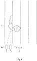
- Fig. 4 shows a further work table with support elements 1 in a plan view with a sensor 5, 6, a transmitter 5a and a receiver 6 being arranged in a triangulation method.
- the sensor 5, 6 can detect deposits 4 and foreign parts 7.
- the sensor 5, 6 can be moved between the spaces between the support elements 1 in a direction 3 perpendicular to the support elements 1.
- Fig. 5 shows a lifting system 9, the forks or prongs 8 of which can be introduced into the interstices of respective support elements 1 under a sheet metal 10 to be transported away.
- the forks or prongs 8 are raised. By lifting the forks or prongs 8, the sheet metal 10 lying on the work table is picked up and it can be transported away from the work table by the lifting system.
- the sensor 5, 6 is, for example, an optical sensor, in particular a laser. Alternatively, an ultrasonic sensor can be used.
- the transmitter and the receiver are arranged opposite one another in such a way that the spaces between adjacent support elements can be checked using the incident light method.
- the transmitter and receiver are therefore arranged above and / or below the work table in this case.
Landscapes
- Engineering & Computer Science (AREA)
- Physics & Mathematics (AREA)
- Optics & Photonics (AREA)
- Mechanical Engineering (AREA)
- Plasma & Fusion (AREA)
- Analytical Chemistry (AREA)
- General Health & Medical Sciences (AREA)
- General Physics & Mathematics (AREA)
- Immunology (AREA)
- Pathology (AREA)
- Biochemistry (AREA)
- Chemical & Material Sciences (AREA)
- Life Sciences & Earth Sciences (AREA)
- Health & Medical Sciences (AREA)
- Laser Beam Processing (AREA)
- Length Measuring Devices By Optical Means (AREA)
Priority Applications (5)
| Application Number | Priority Date | Filing Date | Title |
|---|---|---|---|
| EP19216784.9A EP3838470A1 (fr) | 2019-12-17 | 2019-12-17 | Détection de pièces étrangères et de scories sur une table de travail |
| PCT/EP2020/086004 WO2021122466A1 (fr) | 2019-12-17 | 2020-12-14 | Détection de corps étrangers et de crasses sur une table de travail |
| EP20820464.4A EP4028203B1 (fr) | 2019-12-17 | 2020-12-14 | Détection de pièces étrangères et de scories sur une table de travail |
| CN202080085860.3A CN115023312A (zh) | 2019-12-17 | 2020-12-14 | 工作台上的异物和熔渣的检测 |
| US17/756,353 US12502728B2 (en) | 2019-12-17 | 2020-12-14 | Detection of foreign parts and slag on a worktable |
Applications Claiming Priority (1)
| Application Number | Priority Date | Filing Date | Title |
|---|---|---|---|
| EP19216784.9A EP3838470A1 (fr) | 2019-12-17 | 2019-12-17 | Détection de pièces étrangères et de scories sur une table de travail |
Publications (1)
| Publication Number | Publication Date |
|---|---|
| EP3838470A1 true EP3838470A1 (fr) | 2021-06-23 |
Family
ID=68917761
Family Applications (2)
| Application Number | Title | Priority Date | Filing Date |
|---|---|---|---|
| EP19216784.9A Withdrawn EP3838470A1 (fr) | 2019-12-17 | 2019-12-17 | Détection de pièces étrangères et de scories sur une table de travail |
| EP20820464.4A Active EP4028203B1 (fr) | 2019-12-17 | 2020-12-14 | Détection de pièces étrangères et de scories sur une table de travail |
Family Applications After (1)
| Application Number | Title | Priority Date | Filing Date |
|---|---|---|---|
| EP20820464.4A Active EP4028203B1 (fr) | 2019-12-17 | 2020-12-14 | Détection de pièces étrangères et de scories sur une table de travail |
Country Status (4)
| Country | Link |
|---|---|
| US (1) | US12502728B2 (fr) |
| EP (2) | EP3838470A1 (fr) |
| CN (1) | CN115023312A (fr) |
| WO (1) | WO2021122466A1 (fr) |
Families Citing this family (1)
| Publication number | Priority date | Publication date | Assignee | Title |
|---|---|---|---|---|
| JP7365289B2 (ja) * | 2020-04-23 | 2023-10-19 | 株式会社アマダ | スキッド状態判定装置、スキッド状態判定方法及びレーザ加工システム |
Citations (5)
| Publication number | Priority date | Publication date | Assignee | Title |
|---|---|---|---|---|
| WO2007137613A1 (fr) * | 2006-06-01 | 2007-12-06 | Trumpf Werkzeugmaschinen Gmbh + Co. Kg | Procédé pour nettoyer au moins un élément d'appui de porte-pièce de machine d'usinage |
| JP4339582B2 (ja) | 2002-12-12 | 2009-10-07 | 東海カーボン株式会社 | 燃料電池用セパレータおよびその製造方法 |
| CN201596852U (zh) | 2010-01-19 | 2010-10-06 | 广东大族粤铭激光科技股份有限公司 | 主从式相机配置的智能激光切割系统 |
| DE202010017944U1 (de) * | 2010-08-19 | 2013-03-26 | Trumpf Werkzeugmaschinen Gmbh + Co. Kg | Werkzeugmaschine zum schneidenden Bearbeiten von Werkstücken |
| US20190358748A1 (en) * | 2017-05-23 | 2019-11-28 | Sakai Display Products Corporation | Method for producing device support base and laser cleaning apparatus |
Family Cites Families (15)
| Publication number | Priority date | Publication date | Assignee | Title |
|---|---|---|---|---|
| US4585343A (en) * | 1983-11-04 | 1986-04-29 | Libbey-Owens-Ford Company | Apparatus and method for inspecting glass |
| DE3911112A1 (de) * | 1989-04-06 | 1990-10-11 | Hoefliger Harro Verpackung | Verfahren zum staubfreihalten einer vorrichtung zum feststellen von fremdteilchen |
| JPH04339582A (ja) * | 1991-05-15 | 1992-11-26 | Toshiba Corp | レーザ加工機 |
| US5251010A (en) * | 1991-06-07 | 1993-10-05 | Glasstech, Inc. | Optical roller wave gauge |
| US5495337A (en) * | 1991-11-06 | 1996-02-27 | Machine Vision Products, Inc. | Method of visualizing minute particles |
| FR2697086B1 (fr) * | 1992-10-20 | 1994-12-09 | Thomson Csf | Procédé et dispositif d'inspection de matériau transparent. |
| CA2252308C (fr) * | 1998-10-30 | 2005-01-04 | Image Processing Systems, Inc. | Systeme d'inspection de vitrage |
| US6930772B2 (en) * | 2001-07-05 | 2005-08-16 | Nippon Sheet Glass Company, Limited | Method and device for inspecting defect of sheet-shaped transparent body |
| US7701570B2 (en) * | 2005-12-12 | 2010-04-20 | Corning Incorporated | Collimated light method and system for detecting defects in honeycombs |
| DE102007027987B3 (de) * | 2007-06-14 | 2008-10-30 | Trumpf Werkzeugmaschinen Gmbh + Co. Kg | Vorrichtung zur Aufnahme von plattenförmigen Materialien für zumindest einen Trennvorgang |
| US7800009B2 (en) * | 2007-10-30 | 2010-09-21 | Logical Systems Incorporated | Air separator conveyor and vision system |
| EP2082813B1 (fr) * | 2008-01-22 | 2016-06-08 | Trumpf Sachsen GmbH | Dispositif mécanique pour l'entretien et/ou le nettoyage de rails de support d'un support de pièces à usiner |
| US8049878B2 (en) * | 2008-08-22 | 2011-11-01 | Corning Incorporated | Systems and methods for detecting defects in ceramic filter bodies |
| EP2823932B1 (fr) * | 2012-03-08 | 2021-09-29 | Baoshan Iron & Steel Co., Ltd. | Procédé d'ébauchage de panneau de véhicule motorisé |
| DE102017205095B3 (de) * | 2017-03-27 | 2018-06-28 | Trumpf Werkzeugmaschinen Gmbh + Co. Kg | Vorrichtung und Verfahren zum Entnehmen eines Werkstückteils aus einem Restwerkstück |
-
2019
- 2019-12-17 EP EP19216784.9A patent/EP3838470A1/fr not_active Withdrawn
-
2020
- 2020-12-14 US US17/756,353 patent/US12502728B2/en active Active
- 2020-12-14 EP EP20820464.4A patent/EP4028203B1/fr active Active
- 2020-12-14 WO PCT/EP2020/086004 patent/WO2021122466A1/fr not_active Ceased
- 2020-12-14 CN CN202080085860.3A patent/CN115023312A/zh active Pending
Patent Citations (5)
| Publication number | Priority date | Publication date | Assignee | Title |
|---|---|---|---|---|
| JP4339582B2 (ja) | 2002-12-12 | 2009-10-07 | 東海カーボン株式会社 | 燃料電池用セパレータおよびその製造方法 |
| WO2007137613A1 (fr) * | 2006-06-01 | 2007-12-06 | Trumpf Werkzeugmaschinen Gmbh + Co. Kg | Procédé pour nettoyer au moins un élément d'appui de porte-pièce de machine d'usinage |
| CN201596852U (zh) | 2010-01-19 | 2010-10-06 | 广东大族粤铭激光科技股份有限公司 | 主从式相机配置的智能激光切割系统 |
| DE202010017944U1 (de) * | 2010-08-19 | 2013-03-26 | Trumpf Werkzeugmaschinen Gmbh + Co. Kg | Werkzeugmaschine zum schneidenden Bearbeiten von Werkstücken |
| US20190358748A1 (en) * | 2017-05-23 | 2019-11-28 | Sakai Display Products Corporation | Method for producing device support base and laser cleaning apparatus |
Also Published As
| Publication number | Publication date |
|---|---|
| CN115023312A (zh) | 2022-09-06 |
| WO2021122466A1 (fr) | 2021-06-24 |
| US20220410307A1 (en) | 2022-12-29 |
| US12502728B2 (en) | 2025-12-23 |
| EP4028203B1 (fr) | 2023-10-18 |
| EP4028203A1 (fr) | 2022-07-20 |
Similar Documents
| Publication | Publication Date | Title |
|---|---|---|
| EP2662182B1 (fr) | Procédé et dispositif de séparation de produits de traitement sur une machine-outil | |
| EP3140062B1 (fr) | Procédé et appareil de contrôle d'un rivet | |
| EP3143411B1 (fr) | Procédé de détermination de la présence ou absence d'embouts de pipettes jetables dans des porte-embouts | |
| DE102009016288B4 (de) | Verfahren und Vorrichtung für die Ausrichtung von Substraten | |
| DE102014214201B4 (de) | Pressenlinie mit Kameraeinrichtung zur Prozessüberwachung und Verfahren zur Herstellung von Blechformteilen | |
| DE102016123597A1 (de) | Entfernungssystem für die Entfernung von Bearbeitungsspänen und Bearbeitungssystem | |
| EP2988886B1 (fr) | Train de presses de fabrication de pièces façonnées en tôle, comprenant au moins un dispositif de mesure pour vérifier les pièces produites | |
| DE102017205095B3 (de) | Vorrichtung und Verfahren zum Entnehmen eines Werkstückteils aus einem Restwerkstück | |
| EP3316181A1 (fr) | Procédé de détection d'objets dans un entrepôt et chariot élévateur doté d'un dispositif de détection d'objets dans un entrepôt | |
| WO1986006676A1 (fr) | Procede et installation pour decouper automatiquement des pieces a faces planes et paralleles | |
| DE102008002753B4 (de) | Verfahren zur optischen Inspektion, Detektion und Visualisierung von Defekten auf scheibenförmigen Objekten | |
| EP3838470A1 (fr) | Détection de pièces étrangères et de scories sur une table de travail | |
| DE3331393C2 (de) | Verfahren zur Bestimmung der Lage des Mittelpunktes eines kreisförmigen Werkstückes | |
| WO2023110135A1 (fr) | Procédé et dispositif de détermination de la pose d'articles incurvés et de fixation desdits articles | |
| DE102012020585A1 (de) | Vorrichtung und Verfahren zum Fixieren von flächigen, ansaugfähigen Objekten | |
| DE102019129417B4 (de) | Verfahren zum automatischen Handhaben von Objekten | |
| DE102014001188A1 (de) | Verfahren zur Ermittlung der Höhenprofile gestapelter Bauteile in einem Ladungsträger | |
| EP1524063A1 (fr) | Dispositif de marquage et procédé de ramassage contrôlé de pièces coupées ou estampées dans une plaque | |
| DE102010037486B4 (de) | Verfahren zum Entnehmen von beim Schneiden eines Werkstücks anfallenden Gut- und Restteilen sowie zugehörige Laserbearbeitungsmaschine | |
| DE102016106772A1 (de) | Verfahren und Vorrichtung zum Identifizieren und/oder Sortieren von Glasplatten | |
| EP4543621A1 (fr) | Procédé d?insertion d?un faisceau laser d?un machine de découpe au laser dans une pièce de type plaque pour découper une partie de pièce à partir de la pièce le long d?un contour de découpe prédéterminé sur la pièce | |
| WO2007137567A1 (fr) | Dispositif de mesure servant à mesurer plusieurs sections de tuyau | |
| DE102019206756A1 (de) | Produktionssystem und Produktionssteuerungsverfahren mit Ortungssystem-basierter Simulation von Produktionsabläufen | |
| DE102019130572B3 (de) | Stückguterfassungsanordnung | |
| DE102010051935A1 (de) | Verfahren zum Entnehmen eines Bauteils |
Legal Events
| Date | Code | Title | Description |
|---|---|---|---|
| PUAI | Public reference made under article 153(3) epc to a published international application that has entered the european phase |
Free format text: ORIGINAL CODE: 0009012 |
|
| STAA | Information on the status of an ep patent application or granted ep patent |
Free format text: STATUS: THE APPLICATION HAS BEEN PUBLISHED |
|
| AK | Designated contracting states |
Kind code of ref document: A1 Designated state(s): AL AT BE BG CH CY CZ DE DK EE ES FI FR GB GR HR HU IE IS IT LI LT LU LV MC MK MT NL NO PL PT RO RS SE SI SK SM TR |
|
| STAA | Information on the status of an ep patent application or granted ep patent |
Free format text: STATUS: THE APPLICATION IS DEEMED TO BE WITHDRAWN |
|
| 18D | Application deemed to be withdrawn |
Effective date: 20211224 |