EP3838514B1 - Greifereinheit - Google Patents
Greifereinheit Download PDFInfo
- Publication number
- EP3838514B1 EP3838514B1 EP20214875.5A EP20214875A EP3838514B1 EP 3838514 B1 EP3838514 B1 EP 3838514B1 EP 20214875 A EP20214875 A EP 20214875A EP 3838514 B1 EP3838514 B1 EP 3838514B1
- Authority
- EP
- European Patent Office
- Prior art keywords
- gripper unit
- suction cup
- vacuum
- housing
- gripper
- Prior art date
- Legal status (The legal status is an assumption and is not a legal conclusion. Google has not performed a legal analysis and makes no representation as to the accuracy of the status listed.)
- Active
Links
Images


Classifications
-
- B—PERFORMING OPERATIONS; TRANSPORTING
- B25—HAND TOOLS; PORTABLE POWER-DRIVEN TOOLS; MANIPULATORS
- B25J—MANIPULATORS; CHAMBERS PROVIDED WITH MANIPULATION DEVICES
- B25J15/00—Gripping heads and other end effectors
- B25J15/06—Gripping heads and other end effectors with vacuum or magnetic holding means
- B25J15/0616—Gripping heads and other end effectors with vacuum or magnetic holding means with vacuum
Definitions
- the invention relates to a gripper unit, and in particular to a gripper unit being configured to attain, maintain, and terminate an interface between machinery and a packaging container.
- Individual packaging containers such as liquid food packaging containers, are typically produced from a carton-based material and filled using a high-speed filling machine.
- the filled, formed, and sealed packaging containers are unloaded from the filling machine they are typically transferred to a cardboard packer in which a predetermined number of packaging containers are stacked in a packing pattern and placed in a case made from a cardboard blank, or to a film machine or similar equipment that encloses groups of packaging containers.
- packaging containers need to be moved from the filling machine (or any conveyor associated thereto) to the cardboard packer (or any conveyor associated thereto).
- a robot arm In order to move packages from one area to another within industrial machine equipment, a robot arm can be used.
- the robot arm may be programmed to move in three dimensions with various degrees of freedom.
- a gripper At the distal end of the robot arm, a gripper is arranged providing an interface between the machine and the packaging container.
- Such packaging container interfaces are traditionally mechanical grippers, or vacuum cup grippers that operate on the upper plane of the packaging container.
- prior art grippers do not provide the speed nor stability required for the cycle time that is typically needed, i.e. the time needed to perform one complete operation. In modern manufacturing, grippers must be able to perform a complete handling sequence in 1 second or less.
- gripper unit comprises a vacuum distribution unit connected to a housing such that linear motion of the vacuum distribution unit is allowed in a first direction towards and away from the housing. This improves accuracy of the gripper unit.
- the gripper unit comprises at least a first leaf spring connecting the vacuum distribution unit to the housing.
- the gripper unit further comprises at least one additional leaf spring connecting the vacuum distribution unit to the housing.
- the at least one additional leaf spring has substantially the same length as the first leaf spring.
- the at least one additional leaf spring is arranged in parallel with the first leaf spring, but spaced apart in the first direction. Hence, rotation of the vacuum distribution unit is prevented in a plane defined by a central axis of the first leaf spring and a central axis of the additional leaf spring.
- the gripper unit comprises two additional leaf springs arranged on opposite sides of the first leaf spring. Symmetry is thereby achieved.
- the gripper unit may comprise a plurality of gripper units according to the first aspect. In such embodiment it is possible to move a plurality of packaging containers using a single robotic arm.
- the gripper unit comprises at least one vacuum suction cup.
- the at least one suction cup is moveable between an idle position in which the at least one suction cup is arranged completely within a housing of the gripper unit, and an active position in which the at least one suction cup is extending out from said housing.
- the gripper unit comprises at least two suction cups operating in the same plane and being jointly movable between the idle position and the active position. Improved gripping of the packaging container is thereby achieved.
- the position of the at least one suction cup may be controlled using vacuum, which allows for the use of readily available and high quality vacuum generators.
- the gripper unit further comprises a control suction cup. Activation of the control suction cup may urge the at least one suction cup to move from the idle position to the active position, which is advantageous in that a common air supply can be utilized for the attaching suction cups and for the control suction cup.
- the control suction cup may be arranged inside a cavity of the housing, wherein said cavity is closed by a lid against which the control suction cup will apply a vacuum.
- a robotic arm assembly comprises a robot arm, such as an articulated robot arm or a delta robot, and at least one gripper unit according to the first aspect being provided on the robot arm.
- a robotic arm assembly 1 according to an embodiment is schematically shown.
- the robotic arm assembly 1 comprises a robotic arm 10 and a gripper unit 100, whereby the gripper unit 100 is provided on the distal end of the robotic arm 10.
- the robotic arm 10 is an articulated delta robot, or an articulated robot having at least three rotary joints. Articulated robots, as well as delta robots, are well known in the art and will not be described further herein.
- the robotic arm assembly 1 is arranged in a machine environment, such as between a filling machine and a cardboard packer (not shown) or other type of equipment.
- the robotic arm assembly 1 is provided in order to move individual packaging containers 20, being produced by the filling machine and discharged therefrom by means of a conveyor 30.
- the packaging containers 20, which typically have a main body 22 including at least one planar panel 24, are gripped by the robotic arm assembly 1 as they are transported on the conveyor 30, and moved to a feeding conveyor 40 of the cardboard packer to be transported to further equipment downstream the conveyor 40.
- the planar panel 24 of the main body 22 must not necessarily form an entire side of the packaging container 20, but should preferably be a planar surface big enough to be gripped by the gripper unit 100.
- the robotic arm assembly 1 is configured to operate at very high speed; from an idle position, it must be capable of performing the following motion sequence: arranging the gripper unit 100 in close proximity to the approaching packaging container 20, to activate the gripper unit 100 in order to attach the packaging container 20 to the gripper unit 100, to move the gripper unit 100 and the attached packaging container 20 to the desired position, to release the packaging container 20 by deactivating the gripper unit 100, and to return to the idle position.
- the complete motion sequence should typically be performed in less than 1 second, such as below 0.5 seconds, even more preferably below 0.3 seconds.
- a controller 50 is therefore provided and connected to the gripper unit 100 in order to control activation and deactivation of the gripper unit 100.
- the controller 50 is also in communication with the robotic arm 10.
- the controller 50 preferably comprises a non-transitory computer-readable storage medium, storing one or more programs configured for execution by one or more processors, the one or more programs comprising instructions for controlling the gripper unit 100.
- the gripper unit 100 is a vacuum gripper unit 100 being capable of attaching an adjacent packaging container by applying a suction force using one or more vacuum cups 130.
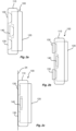
- the gripper unit 100 comprises a housing 110 and a vacuum distribution unit 120.
- the vacuum distribution unit 120 is moveable in relation to the housing 110, and comprises at least one suction cup 130.
- the vacuum distribution unit 120 comprises two spaced apart suction cups 130 for attaching to the packaging container by applying vacuum, and one control suction cup 140.
- All suction cups 130, 140 are preferably activated simultaneously. This is particularly the case when the suction cups 130, 140 share a common air supply (as will be described later).
- the vacuum distribution unit 120 is moved towards the housing 110, in the direction indicated by the block arrow in Fig. 2a . Hence, the vacuum distribution unit 120 is moved from an idle position (shown in Fig. 2a ) to an active position (shown in Fig. 2b ).
- the suction cups 130 are arranged in an extended position, i.e. the distal end of each suction cup 130 is arranged outside the housing 110.
- the gripper unit 100 In the active position, as shown in Fig. 2b , the gripper unit 100 is ready to grip a packaging container. As vacuum is applied, upon activation of the suction cups 130, 140, a suction force is generated in each suction cup 130, 140 thereby pulling the packaging container, as shown in Fig. 2c towards the housing 110. Due to the flexible material of the suction cups 130, the planar panel 24 of the packaging container will be in contact, and flush with, the housing 110.
- the gripper unit 100 is used to collate individual packaging containers while they are in motion, necessitating the activation of the suction cups 130.
- the vacuum operated suction cups 130 need to interfere with the packaging containers that they are picking in order to attain a seal, and therefore a robust grip.
- the gripper unit 100 described herein is configured to retract the suction cups 130, leaving a "clean" housing surface that does not impede packaging container movement.
- the suction cups 130 are controlled to protrude to ensure the suction cups 130 meet the packaging container before the housing 110.
- the suction cups 130 are retracted by cutting off air supply to the vacuum generators 150, 152 (see Fig. 5 ), in order to ensure the suction cups 130 do not interfere with packaging containers being placed.
- three vacuum cups 130, 140 are employed and mounted together on the common vacuum distribution unit 120.
- Two suction cups 130 are configured to grip the packaging container 20, and the third suction cup 140 acts as an actuator to pull the vacuum distribution unit 120 forwards.
- the suction cups 130 used to attach to the packaging container 20 are connected to a common vacuum generator 150 (seen in Fig. 5 ), forming part of the vacuum distribution unit 120.
- the vacuum generator 150 is designed for porous material, thus being capable of generating high flow and low vacuum. This will reduce the grip time, and ensure that the packaging material of the packaging container 20 is undamaged.
- the control suction cup 140 is arranged inside a cavity 112 of the housing 110, wherein the cavity 112 is closed in the plane of the surface of the housing 110 by means of a lid 114.
- the control suction cup 140 is activated, preferably by means of a separate vacuum generator 152 (see Fig. 5 )
- the vacuum will pull the entire vacuum distribution unit 120 towards the housing 110 as the control suction cup 140 applies the suction force against the inside of the lid 114.
- Fig. 4 where the distal end of each suction cup 130 extends out from the housing 110 to some extent.
- the vacuum distribution unit 120 comprises a rigid frame 122 to which the suction cups 130, the control suction cup 140, vacuum generators 150, 152, and an air supply connection 154 (see Fig. 3 ) are mounted. Yet further, the vacuum distribution unit 120 may be provided with a vacuum transducer 160 in order to allow for condition monitoring of the suction cups 130, or to ensure that a "grip" has been attained between the gripper unit 100 and the packaging container 20.
- the vacuum generators 150, 152 may share a common air supply 154, thus making the connection of the gripper-unit 100 both simple and fast when change-overs or replacements of components are needed. As can be further seen in the drawings, the vacuum generators 150, 152 and the suction cups 130, 140 are placed in extreme proximity, thereby reducing the reaction times for pick and place of packaging containers 20.
- An additional advantage of the gripper unit 100 is that the low-profile design allows the gripper unit 100 to work in close proximity to other packaging containers without causing crashes or collisions, and again reducing cycle time.
- the gripper unit 100 reduces lost time by creating high-flow low-vacuum at the exact point of need, in a design that is dimensioned to reduce air consumption, and to reduce areas that are subjected to the vacuum. These features reduce the time needed to create a positive bond between the gripper unit 100 and an adjacent packaging container 20, and similarly reduce the time needed to release the bond.
- the gripper unit 100 has no sliding or rotating parts; the lifetime will benefit from this.
- the vacuum distribution unit 120 should be allowed to move relative the housing 110 as explained above. Even more preferably, the vacuum distribution unit 120 should also be allowed to automatically return to its idle position once the control suction cup 140 is de-activated.
- a gripper unit 100 is proposed where a housing 110 is connected to a vacuum distribution unit 120 in a way that allows for a linear motion of the vacuum distribution unit 120 towards and away from the housing 110, while at the same time preventing movement of the vacuum distribution unit 120 in any other direction.
- a first leaf spring 170 interconnects the housing 110 and the vacuum distribution unit 120.
- the first leaf spring 170 provides a resilient suspension allowing movement in the directions of the planar surfaces of the leaf spring 170 (up or down in the view of Fig. 5 ), and it also provides a suspension which is rigid in the cross directions of these planar surfaces.
- the first leaf spring 170 is arranged at an inner part of the gripper unit 100, facing the robotic arm 10 during use, connecting the housing 110 to the rigid frame 122 of the vacuum distribution unit 120.
- Two additional leaf springs 172 are also provided, spaced apart from the first leaf spring 170.
- the two additional leaf springs 172 (of which only one is shown in Fig. 5 ) are arranged at a level closer to the suction cups 130, as indicated in Fig. 5 . All leaf springs 170, 172 are arranged in parallel.
- One of the additional leaf springs 172 is extending approximately in a direction being aligned with the longitudinal direction of the vacuum generator 150, while the other of the additional leaf springs 172 is extending approximately in a direction being aligned with the longitudinal direction of the vacuum generator 152 (see Fig. 7 , in which the two additional leaf springs 172 are visible).
- the motion of the vacuum distribution unit 120 is physically constrained by leaf springs 170, 172, which protect the vacuum distribution unit 120 against overtravel.
- the housing 110 is provided with two spaced apart T-shaped members 180 which form stop surfaces for the vacuum distribution unit 120 during activation and de-activation of the suction cups 130, 140. Due to the arrangement of the leaf springs 170, 172, the motion is guided in a pure longitudinal direction by use of the leaf springs 170, 172 disposed in a parallelogram configuration.
- the beneficial effects of the first leaf spring 170 are thereby enhanced by the arrangement of the additional leaf springs 172 interconnecting the vacuum distribution unit 120 and the housing 110.
- the arrangement of the additional leaf springs 172 further reduces the freedom of movement of the vacuum distribution unit 120, such that it may essentially only move up and down in the first direction, as limited by a constant radii provided by each leaf spring 170, 172.
- the addition of the additional leaf springs 172 reduces any torsion along the length direction of the primary leaf spring 170 or any bending of the leaf spring 170. Furthermore, arranging essentially equally long leaf springs 170, 172 in parallel but separated in the motion direction, provides a means of maintaining the orientation of the vacuum distribution unit 120, meaning that the vacuum distribution unit 120 is prevented from rotating.
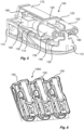
- a gripper unit assembly 1000 comprises at least one gripper unit 100, in this embodiment three gripper units 100 are arranged in parallel, and mounted together.
- the gripper units 100 are arranged in a common housing (not shown) so that the robotic arm 10 (see Fig. 1 ) can be connected to the common housing.
- the gripper unit assembly 1000 can be used to move three packaging containers at the same time, as long as the packaging containers are positioned relative each other so that they fit with the dimensions of the gripper unit assembly 1000.
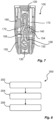
- FIG. 7 shows how the first vacuum generator 150 is connected to both suction cups 130 by means of a common fluid channel 156.
- the vacuum transducer 160 is also connected to the common fluid channel 156 so that the vacuum level can be measured accurately.
- the second vacuum generator 152 is connected to the control suction cup 140 via a control fluid channel 158.
- a method 200 for a gripper unit 100 is schematically shown.
- the gripper unit 100 is activated to move at least one suction cup 130 out from a housing 110, so that the at least one suction cup 130 protrudes from the housing surface.
- the at least one suction cup 130 is positioned close to a packaging container 20, and gripping the packaging container 20 because of the applied vacuum.
- the gripper unit 100 is deactivated thereby pulling the at least on suction cup 130 back into the housing, and the at least one suction cup 130 is also deactivated simultaneously to release the vacuum and hence also the grip of the packaging container 20.
Landscapes
- Engineering & Computer Science (AREA)
- Robotics (AREA)
- Mechanical Engineering (AREA)
- Manipulator (AREA)
- Supplying Of Containers To The Packaging Station (AREA)
Claims (10)
- Greifereinheit (100), umfassend ein Gehäuse (110) und eine Unterdruckverteilungseinheit (120), die mit dem Gehäuse (110) verbunden sind, so dass eine lineare Bewegung der Unterdruckverteilungseinheit (120) in einer ersten Richtung zu dem Gehäuse (110) hin und davon weg gestattet ist, wobei die Greifereinheit (100) Folgendes umfasst:- mindestens eine erste Blattfeder (170), die die Unterdruckverteilungseinheit (120) mit dem Gehäuse (110) verbindet,- mindestens einen Vakuum-Saugnapf (130), wobei der mindestens eine Saugnapf (130) zwischen einer Ruheposition, in der der mindestens eine Saugnapf (130) vollständig in dem Gehäuse (110) der Greifereinheit (100) angeordnet ist, und einer Wirkposition, in der sich der mindestens eine Saugnapf (130) aus dem Gehäuse (110) herauserstreckt, beweglich ist,wobei die Position des mindestens einen Saugnapfs (130) unter Verwendung von Unterdruck gesteuert wird,dadurch gekennzeichnet, dass sie ferner einen Steuer-Saugnapf (140) umfasst.
- Greifereinheit (100) nach Anspruch 1, ferner umfassend mindestens eine zusätzliche Blattfeder (172), die die Unterdruckverteilungseinheit (120) mit dem Gehäuse (110) verbindet.
- Greifereinheit (100) nach Anspruch 2, wobei die mindestens eine zusätzliche Blattfeder (172) im Wesentlichen die gleiche Länge wie die erste Blattfeder (170) aufweist.
- Greifereinheit (100) nach Anspruch 2 oder 3, wobei die mindestens eine zusätzliche Blattfeder (172) parallel zu der ersten Blattfeder (170), aber in der ersten Richtung beabstandet angeordnet ist.
- Greifereinheit (100) nach einem der Ansprüche 2 - 4, umfassend zwei zusätzliche Blattfedern (172), die auf gegenüberliegenden Seiten der ersten Blattfeder (170) angeordnet sind.
- Greifereinheit (100) nach einem der vorhergehenden Ansprüche, umfassend mindestens zwei Saugnäpfe (130), die in der gleichen Ebene wirken und gemeinsam zwischen der Ruhestellung und der Wirkstellung bewegbar sind.
- Greifereinheit (100) nach einem der vorhergehenden Ansprüche, wobei der mindestens eine Saugnapf (130) durch die Aktivierung des Steuer-Saugnapfs (140) dazu gedrängt wird, sich aus der Ruheposition in die Wirkposition zu bewegen.
- Greifereinheit (100) nach Anspruch 7, wobei der Steuer-Saugnapf (140) in einem Hohlraum (112) des Gehäuses (110) angeordnet ist, wobei der Hohlraum (112) durch einen Deckel (114) verschlossen ist, gegen den der Steuer-Saugnapf (140) einen Unterdruck anlegt.
- Greifereinheitsbaugruppe (1000), umfassend eine Vielzahl von Greifereinheiten (100) nach einem der vorhergehenden Ansprüche.
- Roboterarmbaugruppe (1), umfassend einen Roboterarm (10) und mindestens eine an dem Roboterarm (10) vorgesehene Greifereinheit (100) nach einem der Ansprüche 1 - 8.
Applications Claiming Priority (1)
| Application Number | Priority Date | Filing Date | Title |
|---|---|---|---|
| EP19217884 | 2019-12-19 |
Publications (2)
| Publication Number | Publication Date |
|---|---|
| EP3838514A1 EP3838514A1 (de) | 2021-06-23 |
| EP3838514B1 true EP3838514B1 (de) | 2025-04-02 |
Family
ID=68965816
Family Applications (1)
| Application Number | Title | Priority Date | Filing Date |
|---|---|---|---|
| EP20214875.5A Active EP3838514B1 (de) | 2019-12-19 | 2020-12-17 | Greifereinheit |
Country Status (5)
| Country | Link |
|---|---|
| US (1) | US20220410408A1 (de) |
| EP (1) | EP3838514B1 (de) |
| JP (1) | JP2023507417A (de) |
| CN (1) | CN114761187A (de) |
| WO (1) | WO2021122930A1 (de) |
Citations (2)
| Publication number | Priority date | Publication date | Assignee | Title |
|---|---|---|---|---|
| EP2414138B1 (de) * | 2009-03-31 | 2014-06-25 | ATS Automation Tooling Systems Inc. | Mit federn stabilisierte vakuumgreiferanordnung |
| JP2017075029A (ja) * | 2015-10-15 | 2017-04-20 | 大森機械工業株式会社 | 吸引装置、フィルム接合装置、搬送装置 |
Family Cites Families (9)
| Publication number | Priority date | Publication date | Assignee | Title |
|---|---|---|---|---|
| US3820667A (en) * | 1972-12-12 | 1974-06-28 | Materials Management Syst Inc | Article handling machine |
| US4828304A (en) * | 1986-09-09 | 1989-05-09 | Kabushiki Kaisha Yakult Honsha | Vacuum adsorption hand |
| JPH0691577A (ja) * | 1992-09-08 | 1994-04-05 | Seiko Epson Corp | 吸着ヘッド |
| US7000964B1 (en) * | 2004-03-31 | 2006-02-21 | Bakery Holdings Llc | Vacuum flow suction cup assembly |
| US7481472B2 (en) * | 2005-03-15 | 2009-01-27 | Sage Automation, Inc. | Layer picking end effector system, apparatus and method |
| DE102006022278A1 (de) * | 2006-05-11 | 2007-11-15 | Deutsche Post Ag | Greifsystem für gestapeltes Stückgut |
| JP2010076929A (ja) * | 2008-09-29 | 2010-04-08 | Ushio Inc | 基板搬送アーム |
| JP5945968B2 (ja) * | 2013-09-03 | 2016-07-05 | 株式会社安川電機 | ロボットハンド、ロボットシステム、及び物品のデパレタイズ方法 |
| CN108161968A (zh) * | 2018-02-02 | 2018-06-15 | 苏州瓦泊特智能科技有限公司 | 一种机器人用负压吸附装置 |
-
2020
- 2020-12-17 JP JP2022537332A patent/JP2023507417A/ja active Pending
- 2020-12-17 US US17/771,479 patent/US20220410408A1/en active Pending
- 2020-12-17 CN CN202080084924.8A patent/CN114761187A/zh active Pending
- 2020-12-17 WO PCT/EP2020/086685 patent/WO2021122930A1/en not_active Ceased
- 2020-12-17 EP EP20214875.5A patent/EP3838514B1/de active Active
Patent Citations (2)
| Publication number | Priority date | Publication date | Assignee | Title |
|---|---|---|---|---|
| EP2414138B1 (de) * | 2009-03-31 | 2014-06-25 | ATS Automation Tooling Systems Inc. | Mit federn stabilisierte vakuumgreiferanordnung |
| JP2017075029A (ja) * | 2015-10-15 | 2017-04-20 | 大森機械工業株式会社 | 吸引装置、フィルム接合装置、搬送装置 |
Also Published As
| Publication number | Publication date |
|---|---|
| US20220410408A1 (en) | 2022-12-29 |
| WO2021122930A1 (en) | 2021-06-24 |
| CN114761187A (zh) | 2022-07-15 |
| EP3838514A1 (de) | 2021-06-23 |
| JP2023507417A (ja) | 2023-02-22 |
Similar Documents
| Publication | Publication Date | Title |
|---|---|---|
| JP7727046B2 (ja) | ロボットハンド、ロボット及びロボットシステム | |
| US7409812B2 (en) | Robotic packaging device and method | |
| US20090320417A1 (en) | Linear actuated robotic packaging device and method | |
| JP4026773B2 (ja) | 食材の把持移動方法及び装置 | |
| EP2617535A2 (de) | Roboter, Roboterhand und Verfahren zur Anpassung der Halteposition einer Roboterhand | |
| US20170106534A1 (en) | Transporter and transport method | |
| US20180029807A1 (en) | Suction device | |
| WO2020138344A1 (ja) | エンドエフェクタ及びそれが装着されたロボット | |
| US20190337164A1 (en) | Transferring system and method of operating the same | |
| EP2463065A1 (de) | Vakuumgreifkopf für einen Industrieroboter | |
| US20220193929A1 (en) | Holding device and robot provided with same | |
| US20190375521A1 (en) | Boxing device and boxing method | |
| EP3838514B1 (de) | Greifereinheit | |
| EP3838515A1 (de) | Greifereinheit | |
| JP2011131340A (ja) | ハンド装置 | |
| CN1284712C (zh) | 用于拾取坯料堆垛的方法和装置 | |
| EP3878777A1 (de) | Greiferschnorchelanordnung | |
| CN210819556U (zh) | 一种机械密封件组装机用机械手 | |
| JP2025034657A (ja) | 吸着ハンド及びロボット装置 | |
| JP6694917B2 (ja) | ロボットハンド、及びロボット | |
| CN115151389A (zh) | 推动器装置 | |
| CN120916887A (zh) | 用于填充镜片模具组件的机器 | |
| di Meccanica | PNEUMATIC SENSORS: THEIR USE AND PERFORMANCE IN FORCE, TACTILE AND POSITION SENSING AND IN SHAPE RECOGNITION | |
| Romiti | Pneumatic sensors: their use and performance in force, tactile and position sensing and in shape recognition | |
| WO2021172977A1 (en) | A packaging apparatus and its method thereof |
Legal Events
| Date | Code | Title | Description |
|---|---|---|---|
| PUAI | Public reference made under article 153(3) epc to a published international application that has entered the european phase |
Free format text: ORIGINAL CODE: 0009012 |
|
| STAA | Information on the status of an ep patent application or granted ep patent |
Free format text: STATUS: THE APPLICATION HAS BEEN PUBLISHED |
|
| AK | Designated contracting states |
Kind code of ref document: A1 Designated state(s): AL AT BE BG CH CY CZ DE DK EE ES FI FR GB GR HR HU IE IS IT LI LT LU LV MC MK MT NL NO PL PT RO RS SE SI SK SM TR |
|
| STAA | Information on the status of an ep patent application or granted ep patent |
Free format text: STATUS: REQUEST FOR EXAMINATION WAS MADE |
|
| 17P | Request for examination filed |
Effective date: 20211223 |
|
| RBV | Designated contracting states (corrected) |
Designated state(s): AL AT BE BG CH CY CZ DE DK EE ES FI FR GB GR HR HU IE IS IT LI LT LU LV MC MK MT NL NO PL PT RO RS SE SI SK SM TR |
|
| STAA | Information on the status of an ep patent application or granted ep patent |
Free format text: STATUS: EXAMINATION IS IN PROGRESS |
|
| 17Q | First examination report despatched |
Effective date: 20230801 |
|
| GRAP | Despatch of communication of intention to grant a patent |
Free format text: ORIGINAL CODE: EPIDOSNIGR1 |
|
| STAA | Information on the status of an ep patent application or granted ep patent |
Free format text: STATUS: GRANT OF PATENT IS INTENDED |
|
| INTG | Intention to grant announced |
Effective date: 20241217 |
|
| GRAS | Grant fee paid |
Free format text: ORIGINAL CODE: EPIDOSNIGR3 |
|
| GRAA | (expected) grant |
Free format text: ORIGINAL CODE: 0009210 |
|
| STAA | Information on the status of an ep patent application or granted ep patent |
Free format text: STATUS: THE PATENT HAS BEEN GRANTED |
|
| P01 | Opt-out of the competence of the unified patent court (upc) registered |
Free format text: CASE NUMBER: APP_8374/2025 Effective date: 20250219 |
|
| AK | Designated contracting states |
Kind code of ref document: B1 Designated state(s): AL AT BE BG CH CY CZ DE DK EE ES FI FR GB GR HR HU IE IS IT LI LT LU LV MC MK MT NL NO PL PT RO RS SE SI SK SM TR |
|
| REG | Reference to a national code |
Ref country code: GB Ref legal event code: FG4D |
|
| REG | Reference to a national code |
Ref country code: CH Ref legal event code: EP |
|
| REG | Reference to a national code |
Ref country code: DE Ref legal event code: R096 Ref document number: 602020048652 Country of ref document: DE |
|
| REG | Reference to a national code |
Ref country code: IE Ref legal event code: FG4D |
|
| REG | Reference to a national code |
Ref country code: NL Ref legal event code: MP Effective date: 20250402 |
|
| PG25 | Lapsed in a contracting state [announced via postgrant information from national office to epo] |
Ref country code: NL Free format text: LAPSE BECAUSE OF FAILURE TO SUBMIT A TRANSLATION OF THE DESCRIPTION OR TO PAY THE FEE WITHIN THE PRESCRIBED TIME-LIMIT Effective date: 20250402 |
|
| REG | Reference to a national code |
Ref country code: AT Ref legal event code: MK05 Ref document number: 1780861 Country of ref document: AT Kind code of ref document: T Effective date: 20250402 |
|
| PG25 | Lapsed in a contracting state [announced via postgrant information from national office to epo] |
Ref country code: ES Free format text: LAPSE BECAUSE OF FAILURE TO SUBMIT A TRANSLATION OF THE DESCRIPTION OR TO PAY THE FEE WITHIN THE PRESCRIBED TIME-LIMIT Effective date: 20250402 Ref country code: FI Free format text: LAPSE BECAUSE OF FAILURE TO SUBMIT A TRANSLATION OF THE DESCRIPTION OR TO PAY THE FEE WITHIN THE PRESCRIBED TIME-LIMIT Effective date: 20250402 Ref country code: PT Free format text: LAPSE BECAUSE OF FAILURE TO SUBMIT A TRANSLATION OF THE DESCRIPTION OR TO PAY THE FEE WITHIN THE PRESCRIBED TIME-LIMIT Effective date: 20250804 |
|
| REG | Reference to a national code |
Ref country code: LT Ref legal event code: MG9D |
|
| PG25 | Lapsed in a contracting state [announced via postgrant information from national office to epo] |
Ref country code: NO Free format text: LAPSE BECAUSE OF FAILURE TO SUBMIT A TRANSLATION OF THE DESCRIPTION OR TO PAY THE FEE WITHIN THE PRESCRIBED TIME-LIMIT Effective date: 20250702 Ref country code: GR Free format text: LAPSE BECAUSE OF FAILURE TO SUBMIT A TRANSLATION OF THE DESCRIPTION OR TO PAY THE FEE WITHIN THE PRESCRIBED TIME-LIMIT Effective date: 20250703 |
|
| PG25 | Lapsed in a contracting state [announced via postgrant information from national office to epo] |
Ref country code: PL Free format text: LAPSE BECAUSE OF FAILURE TO SUBMIT A TRANSLATION OF THE DESCRIPTION OR TO PAY THE FEE WITHIN THE PRESCRIBED TIME-LIMIT Effective date: 20250402 |
|
| PG25 | Lapsed in a contracting state [announced via postgrant information from national office to epo] |
Ref country code: BG Free format text: LAPSE BECAUSE OF FAILURE TO SUBMIT A TRANSLATION OF THE DESCRIPTION OR TO PAY THE FEE WITHIN THE PRESCRIBED TIME-LIMIT Effective date: 20250402 |
|
| PG25 | Lapsed in a contracting state [announced via postgrant information from national office to epo] |
Ref country code: HR Free format text: LAPSE BECAUSE OF FAILURE TO SUBMIT A TRANSLATION OF THE DESCRIPTION OR TO PAY THE FEE WITHIN THE PRESCRIBED TIME-LIMIT Effective date: 20250402 |
|
| PG25 | Lapsed in a contracting state [announced via postgrant information from national office to epo] |
Ref country code: AT Free format text: LAPSE BECAUSE OF FAILURE TO SUBMIT A TRANSLATION OF THE DESCRIPTION OR TO PAY THE FEE WITHIN THE PRESCRIBED TIME-LIMIT Effective date: 20250402 |
|
| PG25 | Lapsed in a contracting state [announced via postgrant information from national office to epo] |
Ref country code: RS Free format text: LAPSE BECAUSE OF FAILURE TO SUBMIT A TRANSLATION OF THE DESCRIPTION OR TO PAY THE FEE WITHIN THE PRESCRIBED TIME-LIMIT Effective date: 20250702 |
|
| PG25 | Lapsed in a contracting state [announced via postgrant information from national office to epo] |
Ref country code: IS Free format text: LAPSE BECAUSE OF FAILURE TO SUBMIT A TRANSLATION OF THE DESCRIPTION OR TO PAY THE FEE WITHIN THE PRESCRIBED TIME-LIMIT Effective date: 20250802 |
|
| PG25 | Lapsed in a contracting state [announced via postgrant information from national office to epo] |
Ref country code: LV Free format text: LAPSE BECAUSE OF FAILURE TO SUBMIT A TRANSLATION OF THE DESCRIPTION OR TO PAY THE FEE WITHIN THE PRESCRIBED TIME-LIMIT Effective date: 20250402 |
|
| REG | Reference to a national code |
Ref country code: DE Ref legal event code: R097 Ref document number: 602020048652 Country of ref document: DE |
|
| PG25 | Lapsed in a contracting state [announced via postgrant information from national office to epo] |
Ref country code: DK Free format text: LAPSE BECAUSE OF FAILURE TO SUBMIT A TRANSLATION OF THE DESCRIPTION OR TO PAY THE FEE WITHIN THE PRESCRIBED TIME-LIMIT Effective date: 20250402 Ref country code: SM Free format text: LAPSE BECAUSE OF FAILURE TO SUBMIT A TRANSLATION OF THE DESCRIPTION OR TO PAY THE FEE WITHIN THE PRESCRIBED TIME-LIMIT Effective date: 20250402 |
|
| PG25 | Lapsed in a contracting state [announced via postgrant information from national office to epo] |
Ref country code: CZ Free format text: LAPSE BECAUSE OF FAILURE TO SUBMIT A TRANSLATION OF THE DESCRIPTION OR TO PAY THE FEE WITHIN THE PRESCRIBED TIME-LIMIT Effective date: 20250402 |
|
| PG25 | Lapsed in a contracting state [announced via postgrant information from national office to epo] |
Ref country code: EE Free format text: LAPSE BECAUSE OF FAILURE TO SUBMIT A TRANSLATION OF THE DESCRIPTION OR TO PAY THE FEE WITHIN THE PRESCRIBED TIME-LIMIT Effective date: 20250402 |
|
| PG25 | Lapsed in a contracting state [announced via postgrant information from national office to epo] |
Ref country code: RO Free format text: LAPSE BECAUSE OF FAILURE TO SUBMIT A TRANSLATION OF THE DESCRIPTION OR TO PAY THE FEE WITHIN THE PRESCRIBED TIME-LIMIT Effective date: 20250402 Ref country code: SK Free format text: LAPSE BECAUSE OF FAILURE TO SUBMIT A TRANSLATION OF THE DESCRIPTION OR TO PAY THE FEE WITHIN THE PRESCRIBED TIME-LIMIT Effective date: 20250402 |
|
| PG25 | Lapsed in a contracting state [announced via postgrant information from national office to epo] |
Ref country code: IT Free format text: LAPSE BECAUSE OF FAILURE TO SUBMIT A TRANSLATION OF THE DESCRIPTION OR TO PAY THE FEE WITHIN THE PRESCRIBED TIME-LIMIT Effective date: 20250402 |
|
| PLBE | No opposition filed within time limit |
Free format text: ORIGINAL CODE: 0009261 |
|
| STAA | Information on the status of an ep patent application or granted ep patent |
Free format text: STATUS: NO OPPOSITION FILED WITHIN TIME LIMIT |
|
| REG | Reference to a national code |
Ref country code: CH Ref legal event code: L10 Free format text: ST27 STATUS EVENT CODE: U-0-0-L10-L00 (AS PROVIDED BY THE NATIONAL OFFICE) Effective date: 20260211 |
|
| 26N | No opposition filed |
Effective date: 20260105 |