EP3838549A1 - Verfahren zur formung eines werkstücks durch kunststoffeinspritzung, und mit den entsprechenden instrumenten ausgestattete form zur umsetzung eines solchen verfahrens - Google Patents
Verfahren zur formung eines werkstücks durch kunststoffeinspritzung, und mit den entsprechenden instrumenten ausgestattete form zur umsetzung eines solchen verfahrens Download PDFInfo
- Publication number
- EP3838549A1 EP3838549A1 EP20214217.0A EP20214217A EP3838549A1 EP 3838549 A1 EP3838549 A1 EP 3838549A1 EP 20214217 A EP20214217 A EP 20214217A EP 3838549 A1 EP3838549 A1 EP 3838549A1
- Authority
- EP
- European Patent Office
- Prior art keywords
- mold
- max
- counter
- characteristic
- cavity
- Prior art date
- Legal status (The legal status is an assumption and is not a legal conclusion. Google has not performed a legal analysis and makes no representation as to the accuracy of the status listed.)
- Withdrawn
Links
- 238000000465 moulding Methods 0.000 title claims abstract description 29
- 238000002347 injection Methods 0.000 title claims abstract description 28
- 239000007924 injection Substances 0.000 title claims abstract description 28
- 238000000034 method Methods 0.000 title claims abstract description 27
- 230000000977 initiatory effect Effects 0.000 claims description 2
- 239000000463 material Substances 0.000 description 13
- 238000012545 processing Methods 0.000 description 10
- 238000009434 installation Methods 0.000 description 5
- 238000005259 measurement Methods 0.000 description 5
- 238000011088 calibration curve Methods 0.000 description 4
- 238000012937 correction Methods 0.000 description 2
- 230000008014 freezing Effects 0.000 description 2
- 238000007710 freezing Methods 0.000 description 2
- 230000006870 function Effects 0.000 description 2
- 238000001746 injection moulding Methods 0.000 description 2
- 238000005070 sampling Methods 0.000 description 2
- 238000001514 detection method Methods 0.000 description 1
- 238000010586 diagram Methods 0.000 description 1
- 238000007373 indentation Methods 0.000 description 1
- 238000004519 manufacturing process Methods 0.000 description 1
- 238000002360 preparation method Methods 0.000 description 1
- 230000002123 temporal effect Effects 0.000 description 1
- 238000012360 testing method Methods 0.000 description 1
Images

Classifications
-
- B—PERFORMING OPERATIONS; TRANSPORTING
- B29—WORKING OF PLASTICS; WORKING OF SUBSTANCES IN A PLASTIC STATE IN GENERAL
- B29C—SHAPING OR JOINING OF PLASTICS; SHAPING OF MATERIAL IN A PLASTIC STATE, NOT OTHERWISE PROVIDED FOR; AFTER-TREATMENT OF THE SHAPED PRODUCTS, e.g. REPAIRING
- B29C45/00—Injection moulding, i.e. forcing the required volume of moulding material through a nozzle into a closed mould; Apparatus therefor
- B29C45/17—Component parts, details or accessories; Auxiliary operations
- B29C45/76—Measuring, controlling or regulating
- B29C45/77—Measuring, controlling or regulating of velocity or pressure of moulding material
-
- B—PERFORMING OPERATIONS; TRANSPORTING
- B29—WORKING OF PLASTICS; WORKING OF SUBSTANCES IN A PLASTIC STATE IN GENERAL
- B29C—SHAPING OR JOINING OF PLASTICS; SHAPING OF MATERIAL IN A PLASTIC STATE, NOT OTHERWISE PROVIDED FOR; AFTER-TREATMENT OF THE SHAPED PRODUCTS, e.g. REPAIRING
- B29C45/00—Injection moulding, i.e. forcing the required volume of moulding material through a nozzle into a closed mould; Apparatus therefor
- B29C45/0053—Injection moulding, i.e. forcing the required volume of moulding material through a nozzle into a closed mould; Apparatus therefor combined with a final operation, e.g. shaping
- B29C45/0055—Shaping
-
- B—PERFORMING OPERATIONS; TRANSPORTING
- B29—WORKING OF PLASTICS; WORKING OF SUBSTANCES IN A PLASTIC STATE IN GENERAL
- B29C—SHAPING OR JOINING OF PLASTICS; SHAPING OF MATERIAL IN A PLASTIC STATE, NOT OTHERWISE PROVIDED FOR; AFTER-TREATMENT OF THE SHAPED PRODUCTS, e.g. REPAIRING
- B29C45/00—Injection moulding, i.e. forcing the required volume of moulding material through a nozzle into a closed mould; Apparatus therefor
- B29C45/17—Component parts, details or accessories; Auxiliary operations
- B29C45/76—Measuring, controlling or regulating
-
- B—PERFORMING OPERATIONS; TRANSPORTING
- B29—WORKING OF PLASTICS; WORKING OF SUBSTANCES IN A PLASTIC STATE IN GENERAL
- B29C—SHAPING OR JOINING OF PLASTICS; SHAPING OF MATERIAL IN A PLASTIC STATE, NOT OTHERWISE PROVIDED FOR; AFTER-TREATMENT OF THE SHAPED PRODUCTS, e.g. REPAIRING
- B29C45/00—Injection moulding, i.e. forcing the required volume of moulding material through a nozzle into a closed mould; Apparatus therefor
- B29C45/17—Component parts, details or accessories; Auxiliary operations
- B29C45/76—Measuring, controlling or regulating
- B29C45/768—Detecting defective moulding conditions
-
- B—PERFORMING OPERATIONS; TRANSPORTING
- B29—WORKING OF PLASTICS; WORKING OF SUBSTANCES IN A PLASTIC STATE IN GENERAL
- B29C—SHAPING OR JOINING OF PLASTICS; SHAPING OF MATERIAL IN A PLASTIC STATE, NOT OTHERWISE PROVIDED FOR; AFTER-TREATMENT OF THE SHAPED PRODUCTS, e.g. REPAIRING
- B29C45/00—Injection moulding, i.e. forcing the required volume of moulding material through a nozzle into a closed mould; Apparatus therefor
- B29C45/17—Component parts, details or accessories; Auxiliary operations
- B29C45/76—Measuring, controlling or regulating
- B29C45/78—Measuring, controlling or regulating of temperature
-
- B—PERFORMING OPERATIONS; TRANSPORTING
- B29—WORKING OF PLASTICS; WORKING OF SUBSTANCES IN A PLASTIC STATE IN GENERAL
- B29C—SHAPING OR JOINING OF PLASTICS; SHAPING OF MATERIAL IN A PLASTIC STATE, NOT OTHERWISE PROVIDED FOR; AFTER-TREATMENT OF THE SHAPED PRODUCTS, e.g. REPAIRING
- B29C2945/00—Indexing scheme relating to injection moulding, i.e. forcing the required volume of moulding material through a nozzle into a closed mould
- B29C2945/76—Measuring, controlling or regulating
- B29C2945/76003—Measured parameter
- B29C2945/76006—Pressure
-
- B—PERFORMING OPERATIONS; TRANSPORTING
- B29—WORKING OF PLASTICS; WORKING OF SUBSTANCES IN A PLASTIC STATE IN GENERAL
- B29C—SHAPING OR JOINING OF PLASTICS; SHAPING OF MATERIAL IN A PLASTIC STATE, NOT OTHERWISE PROVIDED FOR; AFTER-TREATMENT OF THE SHAPED PRODUCTS, e.g. REPAIRING
- B29C2945/00—Indexing scheme relating to injection moulding, i.e. forcing the required volume of moulding material through a nozzle into a closed mould
- B29C2945/76—Measuring, controlling or regulating
- B29C2945/76003—Measured parameter
- B29C2945/7604—Temperature
-
- B—PERFORMING OPERATIONS; TRANSPORTING
- B29—WORKING OF PLASTICS; WORKING OF SUBSTANCES IN A PLASTIC STATE IN GENERAL
- B29C—SHAPING OR JOINING OF PLASTICS; SHAPING OF MATERIAL IN A PLASTIC STATE, NOT OTHERWISE PROVIDED FOR; AFTER-TREATMENT OF THE SHAPED PRODUCTS, e.g. REPAIRING
- B29C2945/00—Indexing scheme relating to injection moulding, i.e. forcing the required volume of moulding material through a nozzle into a closed mould
- B29C2945/76—Measuring, controlling or regulating
- B29C2945/76177—Location of measurement
- B29C2945/76254—Mould
- B29C2945/76257—Mould cavity
-
- B—PERFORMING OPERATIONS; TRANSPORTING
- B29—WORKING OF PLASTICS; WORKING OF SUBSTANCES IN A PLASTIC STATE IN GENERAL
- B29C—SHAPING OR JOINING OF PLASTICS; SHAPING OF MATERIAL IN A PLASTIC STATE, NOT OTHERWISE PROVIDED FOR; AFTER-TREATMENT OF THE SHAPED PRODUCTS, e.g. REPAIRING
- B29C2945/00—Indexing scheme relating to injection moulding, i.e. forcing the required volume of moulding material through a nozzle into a closed mould
- B29C2945/76—Measuring, controlling or regulating
- B29C2945/76344—Phase or stage of measurement
- B29C2945/76381—Injection
-
- B—PERFORMING OPERATIONS; TRANSPORTING
- B29—WORKING OF PLASTICS; WORKING OF SUBSTANCES IN A PLASTIC STATE IN GENERAL
- B29C—SHAPING OR JOINING OF PLASTICS; SHAPING OF MATERIAL IN A PLASTIC STATE, NOT OTHERWISE PROVIDED FOR; AFTER-TREATMENT OF THE SHAPED PRODUCTS, e.g. REPAIRING
- B29C2945/00—Indexing scheme relating to injection moulding, i.e. forcing the required volume of moulding material through a nozzle into a closed mould
- B29C2945/76—Measuring, controlling or regulating
- B29C2945/76344—Phase or stage of measurement
- B29C2945/76384—Holding, dwelling
-
- B—PERFORMING OPERATIONS; TRANSPORTING
- B29—WORKING OF PLASTICS; WORKING OF SUBSTANCES IN A PLASTIC STATE IN GENERAL
- B29C—SHAPING OR JOINING OF PLASTICS; SHAPING OF MATERIAL IN A PLASTIC STATE, NOT OTHERWISE PROVIDED FOR; AFTER-TREATMENT OF THE SHAPED PRODUCTS, e.g. REPAIRING
- B29C2945/00—Indexing scheme relating to injection moulding, i.e. forcing the required volume of moulding material through a nozzle into a closed mould
- B29C2945/76—Measuring, controlling or regulating
- B29C2945/76494—Controlled parameter
- B29C2945/76538—Viscosity
-
- B—PERFORMING OPERATIONS; TRANSPORTING
- B29—WORKING OF PLASTICS; WORKING OF SUBSTANCES IN A PLASTIC STATE IN GENERAL
- B29C—SHAPING OR JOINING OF PLASTICS; SHAPING OF MATERIAL IN A PLASTIC STATE, NOT OTHERWISE PROVIDED FOR; AFTER-TREATMENT OF THE SHAPED PRODUCTS, e.g. REPAIRING
- B29C2945/00—Indexing scheme relating to injection moulding, i.e. forcing the required volume of moulding material through a nozzle into a closed mould
- B29C2945/76—Measuring, controlling or regulating
- B29C2945/76929—Controlling method
- B29C2945/76939—Using stored or historical data sets
- B29C2945/76943—Using stored or historical data sets compare with thresholds
Definitions
- the present invention relates to a method of molding a part by plastic injection.
- the present invention also relates to an instrumented mold intended to implement such a method.
- the invention more particularly intends to remedy, by proposing a molding process allowing simpler and more precise detection of the conformity of molded parts.
- the invention relates to a method of molding a part by plastic injection in a mold.
- this method comprises several steps.
- a first step a) consists in initiating a molding cycle.
- a second step b) quantities characteristic of the quality of the part are measured or calculated, during the molding cycle, using sensors integrated in the mold.
- the characteristic quantities measured or calculated in step b) are compared with reference values and, in a step d), depending on the comparison carried out in step c), the part is declared compliant or non-compliant.
- the sensors integrated into the mold make it possible to facilitate the implementation of the method. Indeed, during the initialization of the molding process, it is no longer necessary to position the sensors, the process is therefore faster to implement and more precise.
- the sensors since the sensors are integrated into the mold, they remain in the same place throughout the life of the mold, which eliminates the play and placement tolerances inherent in removable sensors and allows the measured data to be compared precisely. each time the mold is used.
- the invention also relates to an instrumented mold intended to implement the method described above.
- this mold comprises sensors which are integral with at least one frame of the mold.
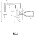
- An instrumented mold 2 is shown schematically on the figure 1 , within an injection molding installation 1.
- This mold 2 comprises a first frame 4 and a second frame 6.
- the mold 2 also comprises an electronic processing unit 10, a pressure sensor 12 and a temperature sensor 14.
- the pressure sensor is integrated into the second frame 6 and transmits information to the processing unit 10 via a link 16, which can be an electrical link as in the figure, or a wireless link.
- the temperature sensor 14 is integrated into the first frame 4 of the mold 2 and transmits information to the processing unit 10 by means of a link 18, which can also be an electrical link as in the figure, or a link without wire.
- the processing unit 10 is placed as close as possible to the sensors 12 and 14.
- the mold 2 defines an indentation 20, formed between the frames 4 and 6 when the mold 2 is closed and which is shown in dotted lines on the figure 1 , to form a plastic injection molded part.
- An injector 22 known per se is associated with the mold 2 within the installation 1.
- the injector 22 is designed to inject a plastic material into the cavity 20 by passing through an injection point 24 defined in the mold 2. In other words, the injector 22 and the cavity 20 communicate thanks to the injection point 24.
- the cavity 20 forms a cavity in the mold 2 connected to the injection point 24.
- the pressure sensor 12 is located in the cavity 20 as close as possible. of the injection point 24 in order to be able to measure the pressure of the injected product delivered by the injector 22, where it is highest.
- the pressure sensor 12 must be positioned as close as possible to the injection point so that, when filling the cavity 20, the pressure sensor 12 is reached by the material when it is has filled between 5% and 30% of the volume of the impression 20.
- the pressure sensor 12 must not be positioned facing the injection point, so that it does not measure the pressure of the screw d 'injection
- the temperature sensor 14 is located in the cavity 20 as far as possible from the injection point 24, where the material arrives last and therefore where it is coldest when it arrives. In other words, the temperature sensor 14 must be positioned so as to be reached by the material when the latter has filled between 70 and 95% of the volume of the cavity 20. The temperature sensor 14 is positioned so that the difference in filling volume between the instant when the material front reaches the pressure sensor 12 and the instant when this same material front reaches the temperature sensor 14, represents more than half of the total volume of the footprint.
- the temperature sensor 12 is integral with the second frame 6, its position is therefore fixed relative to the frame 6.
- the pressure sensor 14 is integral with the frame, its position is therefore fixed relative to the frame 4. This facilitates the preparation of. a cast. This also makes it possible to ensure that the sensors 12 and 14 do not move between two uses of the mold 2, which makes it possible to keep in memory in the processing unit 10 the data recorded by the sensors 12 and 14 and to be able to compare them. to study the evolution of the quality of the parts produced by the mold 2.
- the new sensors 12 and 14 are calibrated, in particular by applying correction coefficients, to correct the differences in the characteristics between the old sensors 12 and 14 and the new sensors 12 and 14.
- a molding cycle is initialized by closing the mold 2.
- quantities characteristic of the quality of the part are measured using the sensors. 12 and 14 integrated into the mold. The measurements are taken in real time, for example every 5 milliseconds.
- the characteristic quantities of the quality of the part are a temperature T and a pressure P.
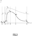
- values of temperature T and pressure P are measured during step 102 and these values are stored in the processing unit 10. These values are stored in the processing unit 10. values of temperature T and pressure P are represented as a function of time t, respectively by the curve in thin line and by the curve in thick line at the figure 3 .
- step 104 the molding cycle ends.
- step 106 which immediately follows step 104 or which is, preferably, simultaneous with step 102 and which precedes the opening of the mold, characteristic points T0 to T3 and P0 to P5, visible on the figure 3 , are selected from among the values measured in step 102.
- t0 to t6 the instants at which the values of the characteristic points are measured.
- the temperature and pressure values at the characteristic points are then compared with calibration or reference values T0 c to T3 c and P0 c to P5 c .
- the calibration values are obtained from an experimentally determined calibration curve, in a case where the quality of the molded part is considered satisfactory.
- the calibration curve represents the result of a campaign of tests of various molding parameters.
- the chosen calibration curve corresponds to the molding parameters minimizing the shear of the injected material.
- the selection of a limited number of characteristic points in the example four characteristic temperature points T0 c to T3 c and six characteristic pressure points P0 c to P5 c , makes it possible to have a fast process and a quantity of recorded data. in the reduced processing unit 10.
- the volume of the cavity 20 being known, knowing the pressure P and the temperature T of the injected material makes it possible to accurately calculate a dynamic viscosity of the injected material, which is an indicator of the quality of the molded part. .
- the instant t0 corresponds to the start of the cycle, and therefore to step 100 at which a pressure P0 and a temperature T0 are measured.
- the instant t1 corresponds to a start of filling of the mold 2, where the pressure P1 is measured. This instant t1 corresponds to the moment when the injected material passes over the pressure sensor 14 and serves as a reference for the rest of the measurements. Indeed, if there is a temporal shift during the arrival of material between the measurements and the calibration curve, a correction coefficient can be applied at the various instants t0 to t6.
- the instant t1 is that from which the pressure measured by the sensor 12 begins to increase.
- the instant t2 corresponds to the end of filling the mold where the pressure P2 and the temperature T1 are measured.
- the instant t3 corresponds to the instant when the temperature in the mold is maximum, here it is the temperature T2 which is measured.
- the instant t4 corresponds to a point of maximum pressure, where the pressure P3 is measured.
- the instant t5 corresponds to an instant of “gate freezing” from which the material at the entrance of the impression 20, that is to say at the injection point 24, freezes. It is the end of application of a pressure by the injector 22. For this point, a pressure P4 is predefined and it is the instant t5 which is measured.
- the instant t6 corresponds to the end of the cycle and therefore to the opening of the mold 2 in step 104. At this step, the pressure P5 and the temperature T3 are measured.
- the characteristic points T0 to T3 and P0 to P5 which are remarkable points on the curve, make it possible to determine the instants t1 to t6.
- the comparison of the characteristic points with the calibration values is carried out by implementing the steps described below, which take place after step 106 or, preferably, in parallel with steps 102 and 106.
- a counter of non-conforming values Cpt_nc is initialized to zero, as well as a temperature index i which is also initiated at zero.
- the temperature index i is compared with a maximum value i max of the temperature index. In the example of the figures, this maximum temperature index value i max is equal to 3.
- a temperature Ti is compared with a calibration temperature Ti c and, if the absolute value of the difference between the two is greater than a value of a predefined tolerance interval AT max , then the counter Cpt_nc is incremented by 1 in a step 114 Then, in a step 116, the temperature index i is incremented by 1. If, in step 112, the difference between the measured temperature Ti and the calibration temperature Ti c is less than the authorized tolerance interval ⁇ T Max , then step 116 is performed directly after step 112. Following step 116, all of steps 110 to 116 are again implemented until the temperature index i is strictly greater than the temperature index.
- a pressure index j is initialized to zero.
- the pressure index j is compared with a maximum pressure index value j max which, in the example of figure 3 , is equal to 5.
- the pressure index j is compared with a particular index value j part .
- This particular index value is, in the example of the figures, equal to 4 and corresponds to the instant of “gate freezing”. If the value of the pressure index j is different from the particular value j part , then a step 122 is implemented. In this step 122, the measured pressure Pj is compared with a calibration or reference pressure Pj c .
- step 124 If an absolute value of a difference between the measured pressure P j and the calibration pressure Pj c is strictly greater than a tolerance interval AP max , then the counter of non-conforming points Cpt_nc is incremented by one in a step 124. Then , a step 126, the pressure counter j is incremented by one. This step 126 is performed directly after step 122 if the absolute value of the difference between the measured pressure P j and the reference pressure Pj c is less than or equal to the tolerance interval ⁇ P Max . At the end of step 126, all of steps 120 to 126 are carried out again until the pressure index j is strictly greater than the maximum pressure index j max .
- step 121 If, in step 121, the pressure counter j is equal to the particular value j leaves , then, in a step 127, the instant tj associated with the pressure value Pj is compared to an instant tj c of calibration or of reference and, if an absolute value of a difference between these two values is strictly greater than a predetermined tolerance interval At max , then the counter of non-conforming points Cpt_nc is incremented by one in a step 128, following which step 126 is implemented. If the value calculated in step 127 is less than or equal to the tolerance interval At max , then step 126 is carried out directly without going through step 127.
- the AP max , AT max and At max tolerance intervals are centered on the calibration values.
- a step 129 is implemented, in which the results obtained for the temperature T and for the pressure P are pooled.
- the final value of the counter of nonconforming points Cpt_nc in which the number of points measured outside the tolerance intervals AP max , AT max and At max is stored, is compared with a threshold value S. If, in step 130, the value of the counter of non-conforming points Cpt_nc is strictly greater than the threshold value S, then, in a step 132, the part is declared non-conforming. If, in step 130, the counter of non-compliant points is less than or equal to the threshold value S, then the part is declared compliant in a step 134.
- steps 104 to 134 are implemented before opening the mold at the end of the molding operation. This makes it possible to know, even before the opening of the mold, whether the part produced is compliant or not and how it must then be treated.
- the calculations of steps 108 to 130 are carried out during the molding cycle, as the cycle progresses.
- the operator can, depending on the data collected, choose to select all the characteristic points T0 to T3 and P0 to P5 or to keep only a part of them. In other words, the operator can use all or part of the criteria mentioned above to determine whether a part is compliant or not. In the case where only part of these criteria is used, the threshold value S is adapted.
- the tolerance intervals ⁇ P max , ⁇ T max and ⁇ t mx are determined, when no molding operation has been carried out in mold 2, with fixed deviation thresholds not depending on installation 1 or mold 2 .
- the data measured during the molding cycles allowing the obtaining of conforming parts are used and the reference values T0 C to T3 C , P0 C to P5 C , as well as the tolerance intervals AP max , AT max and ⁇ t mx are determined using the statistical data acquired during these cycles.
- the reference values T0 X to T3 C and P0 C to P5 C are fixed to the average of the values of the characteristic points T0 to T6 and P0 to P6 and the duration between the instants t0 C and t5 C is fixed at the average of this duration for the measurements carried out previously.
- the tolerance intervals ⁇ P max , ⁇ T max and ⁇ t max are set at three times the standard deviation of the previously measured values.
- the characteristic points T0 to T3 and P0 to P5 the reference values Pi C , Tj C and tj C , the calculated differences and the value of the counter Cpt_nc are stored in the memory of the processing unit 10. This makes it possible to generate a history of the molded parts and to determine which mold 2 and which machine manufactures quality parts or not.
- the pressure 12 and temperature 14 sensors can all be located in the first frame 4 or all in the second frame 6.
- the pressure sensor 14 is integrated into the first frame 4 and the temperature sensor 14 is integrated into the second frame 6.
- the number of impressions 20 present in the mold 2 may vary.
- the mold 2 can include three cavities.
- the mold 2 comprises at least one pressure sensor 12 and one temperature sensor 14 and at most three pressure sensors 12 and three temperature sensors 14, each cavity 20 being provided at most with one pressure sensor 12. and a temperature sensor 14.
- the mold 2 can include a pressure sensor 12 and three temperature sensors 14.
- the mold 2 comprises at least one pressure sensor 12 and one temperature sensor 14, the or each cavity 20 being connected to, at most, a pressure sensor 12 and a temperature sensor 14.
- the number of sensors pressures 12 present in the mold and / or the number of temperature sensors 14 present in the mold may be less than the number of cavities 20, but always greater than or equal to one.
- At least one cavity 20 of the mold 2 is equipped with a pressure sensor 12 and a temperature sensor 14
- the number of characteristic points and of calibration values is different. For example, three times are considered and two temperatures and three pressures are measured and compared to the calibration values.
- steps 118 to 128 can be performed before steps 108 to 116.
- the counter Cpt_nc is initialized to zero during step 118 instead of being initialized during step 110.
- the steps 118 to 128 can be carried out in parallel with the steps 110 to 116.
- a second counter is initialized to zero during the step 118 and the two counters are added in the step 129 for that their sum is compared with the threshold value S in step 130.
- a third time counter can be initialized and a set of steps similar to steps 110 to 126 or 120 to 126 can be implemented to compare all the values of times t0 to t6 with reference values. In this case, steps 121, 127 and 128 are not implemented.
- each characteristic point T0 to T3 and P0 to P5 is compared to its calibration value T0 C to T3 C and P0 C to P5 C and the times at which these values are measured or calculated are also compared with calibration values t0 C to t5 C.
- other quantities can be calculated, for example integrals of pressure and / or temperature between different instants, for example between t5 and t6 or between t4 and t6. Differences in temperature, for example between T3 and T0 and pressure, for example between P4 and P2, can also be calculated and used as indicators of the quality of the molded part.
- the memory can be separate from the processing unit 10. In all cases, it belongs to the mold 2.
- sampling frequency is adjusted as a function of the injection duration.
- the sampling frequency can be between 1ms and 1 second.
- steps 106 to 129 are performed throughout the molding cycle, during data acquisition in step 102.
Landscapes
- Engineering & Computer Science (AREA)
- Manufacturing & Machinery (AREA)
- Mechanical Engineering (AREA)
- Injection Moulding Of Plastics Or The Like (AREA)
Applications Claiming Priority (1)
| Application Number | Priority Date | Filing Date | Title |
|---|---|---|---|
| FR1914452A FR3104482B1 (fr) | 2019-12-16 | 2019-12-16 | Procédé de moulage d’une pièce par injection plastique et moule instrumenté destiné à mettre en œuvre un tel procédé |
Publications (1)
| Publication Number | Publication Date |
|---|---|
| EP3838549A1 true EP3838549A1 (de) | 2021-06-23 |
Family
ID=69903440
Family Applications (1)
| Application Number | Title | Priority Date | Filing Date |
|---|---|---|---|
| EP20214217.0A Withdrawn EP3838549A1 (de) | 2019-12-16 | 2020-12-15 | Verfahren zur formung eines werkstücks durch kunststoffeinspritzung, und mit den entsprechenden instrumenten ausgestattete form zur umsetzung eines solchen verfahrens |
Country Status (3)
| Country | Link |
|---|---|
| EP (1) | EP3838549A1 (de) |
| CN (1) | CN112976521A (de) |
| FR (1) | FR3104482B1 (de) |
Citations (6)
| Publication number | Priority date | Publication date | Assignee | Title |
|---|---|---|---|---|
| JPS59217119A (ja) * | 1983-05-26 | 1984-12-07 | Nissei Plastics Ind Co | 射出成形機の監視方法 |
| EP0317992A2 (de) | 1987-11-25 | 1989-05-31 | Toshiba Kikai Kabushiki Kaisha | Verfahren zur Qualitätsbeurteilung eines spritzgegossenen Produktes |
| US4889667A (en) * | 1983-06-03 | 1989-12-26 | Technoplas Inc. | Method for supervision of injection molding by use of waveform of internal die pressure |
| EP0418398A1 (de) * | 1989-03-28 | 1991-03-27 | Fanuc Ltd. | Anordnung für spritzgiessmaschinen zum unterscheiden brauchbarer teile von ausschussstücken |
| DE102008038930A1 (de) * | 2008-08-13 | 2010-02-18 | Priamus System Technologies Ag | Verfahren zum Regeln bzw. Steuern von Funktionen einer Spritzgiessmaschine |
| CN110001019A (zh) * | 2018-10-01 | 2019-07-12 | 中原大学 | 射出成型设备 |
-
2019
- 2019-12-16 FR FR1914452A patent/FR3104482B1/fr active Active
-
2020
- 2020-12-02 CN CN202011392837.7A patent/CN112976521A/zh active Pending
- 2020-12-15 EP EP20214217.0A patent/EP3838549A1/de not_active Withdrawn
Patent Citations (9)
| Publication number | Priority date | Publication date | Assignee | Title |
|---|---|---|---|---|
| JPS59217119A (ja) * | 1983-05-26 | 1984-12-07 | Nissei Plastics Ind Co | 射出成形機の監視方法 |
| US4889667A (en) * | 1983-06-03 | 1989-12-26 | Technoplas Inc. | Method for supervision of injection molding by use of waveform of internal die pressure |
| EP0317992A2 (de) | 1987-11-25 | 1989-05-31 | Toshiba Kikai Kabushiki Kaisha | Verfahren zur Qualitätsbeurteilung eines spritzgegossenen Produktes |
| EP0317992B1 (de) * | 1987-11-25 | 1993-04-07 | Toshiba Kikai Kabushiki Kaisha | Verfahren zur Qualitätsbeurteilung eines spritzgegossenen Produktes |
| EP0418398A1 (de) * | 1989-03-28 | 1991-03-27 | Fanuc Ltd. | Anordnung für spritzgiessmaschinen zum unterscheiden brauchbarer teile von ausschussstücken |
| EP0418398B1 (de) * | 1989-03-28 | 1995-01-18 | Fanuc Ltd. | Anordnung für spritzgiessmaschinen zum unterscheiden brauchbarer teile von ausschussstücken |
| DE102008038930A1 (de) * | 2008-08-13 | 2010-02-18 | Priamus System Technologies Ag | Verfahren zum Regeln bzw. Steuern von Funktionen einer Spritzgiessmaschine |
| CN110001019A (zh) * | 2018-10-01 | 2019-07-12 | 中原大学 | 射出成型设备 |
| EP3632651A1 (de) * | 2018-10-01 | 2020-04-08 | Chung Yuan Christian University | Spritzgiessmaschine |
Also Published As
| Publication number | Publication date |
|---|---|
| FR3104482B1 (fr) | 2023-04-28 |
| CN112976521A (zh) | 2021-06-18 |
| FR3104482A1 (fr) | 2021-06-18 |
Similar Documents
| Publication | Publication Date | Title |
|---|---|---|
| JP2021146564A (ja) | 成形品判定装置、成形品判定方法、および成形品判定プログラム | |
| EP2911860B1 (de) | Verfahren zur blasformung von behältern und maschine zur durchführung dieses verfahrens | |
| WO2011131892A1 (fr) | Procede et systeme de surveillance du niveau d'huile contenue dans un reservoir d'un moteur d'aeronef | |
| EP2726206B1 (de) | Verfahren zur feststellung von anomalien beim füllen einer flüssigkeitsdosiervorrichtung und flüssigkeitsdosiervorrichtung | |
| FR3106770A1 (fr) | Systeme d’estimation indirecte de l’état d’usure d’un outil coupant | |
| FR3041426A1 (fr) | Procede de calibration automatique d'un capteur d'arbre a cames pour moteur de vehicule automobile | |
| FR2964210A1 (fr) | Systeme de traitement de signaux redondants, procede associe, et aeronef comprenant un tel systeme | |
| FR3104482A1 (fr) | Procédé de moulage d’une pièce par injection plastique et moule instrumenté destiné à mettre en œuvre un tel procédé | |
| JP5570309B2 (ja) | ガスアシスト射出成形用金型装置と成形品の製造方法 | |
| FR2937684A1 (fr) | Procede de determination de la duree d'une dent longue d'une cible montee sur un vilebrequin de moteur a combustion interne | |
| KR20010020317A (ko) | 사출 성형 제어 방법 및 제어 장치 | |
| FR3031768A1 (fr) | Equipement de commande de moteur | |
| FR3067889B1 (fr) | Procede de mesure de vitesse de rotation d'un arbre de turbomachine tenant compte du bruit de mesure | |
| CN114043694B (zh) | 一种注塑对象的重量预测方法、关键参数调整方法及装置 | |
| JP6438428B2 (ja) | 射出成形システム | |
| EP3437018A1 (de) | Verfahren zur messung von winkelgeschwindigkeiten, zugehörige vorrichtung und sensor | |
| EP3234173B1 (de) | Verfahren und vorrichtung zur charakterisierung der inhibitorischen kapazität eines moleküls auf einen mikroorganismus | |
| FR2942851A1 (fr) | Procede d'estimation de la position d'arret d'un moteur a combustion | |
| WO2019193271A1 (fr) | Procédé de calibration automatique d'un capteur d'arbre à cames pour corriger un faux rond de cible | |
| FR3049700A1 (fr) | Procede de fabrication de pieces prenant en compte des derives de fabrication | |
| WO2016087798A1 (fr) | Procédé de fabrication de pièces basé sur l'analyse simultanée d'indicateurs statistiques | |
| EP3379203B1 (de) | Schätzverfahren des bias-fehlers eines sensors | |
| FR2939509A1 (fr) | Procede et systeme d'estimation d'une temperature de veine dans un turboreacteur. | |
| JPS61164812A (ja) | 射出成形機のキヤビテイ内圧測定方法及びその装置 | |
| WO2020182808A1 (fr) | Correction de la mesure de pression d'un capteur de pression de cylindre |
Legal Events
| Date | Code | Title | Description |
|---|---|---|---|
| PUAI | Public reference made under article 153(3) epc to a published international application that has entered the european phase |
Free format text: ORIGINAL CODE: 0009012 |
|
| STAA | Information on the status of an ep patent application or granted ep patent |
Free format text: STATUS: THE APPLICATION HAS BEEN PUBLISHED |
|
| AK | Designated contracting states |
Kind code of ref document: A1 Designated state(s): AL AT BE BG CH CY CZ DE DK EE ES FI FR GB GR HR HU IE IS IT LI LT LU LV MC MK MT NL NO PL PT RO RS SE SI SK SM TR |
|
| STAA | Information on the status of an ep patent application or granted ep patent |
Free format text: STATUS: REQUEST FOR EXAMINATION WAS MADE |
|
| 17P | Request for examination filed |
Effective date: 20211118 |
|
| RBV | Designated contracting states (corrected) |
Designated state(s): AL AT BE BG CH CY CZ DE DK EE ES FI FR GB GR HR HU IE IS IT LI LT LU LV MC MK MT NL NO PL PT RO RS SE SI SK SM TR |
|
| STAA | Information on the status of an ep patent application or granted ep patent |
Free format text: STATUS: EXAMINATION IS IN PROGRESS |
|
| 17Q | First examination report despatched |
Effective date: 20220824 |
|
| STAA | Information on the status of an ep patent application or granted ep patent |
Free format text: STATUS: THE APPLICATION IS DEEMED TO BE WITHDRAWN |
|
| 18D | Application deemed to be withdrawn |
Effective date: 20230104 |