EP3838567A1 - Verfahren und vorrichtung zum giessen einer spritzerfreien polymermischung - Google Patents
Verfahren und vorrichtung zum giessen einer spritzerfreien polymermischung Download PDFInfo
- Publication number
- EP3838567A1 EP3838567A1 EP20215835.8A EP20215835A EP3838567A1 EP 3838567 A1 EP3838567 A1 EP 3838567A1 EP 20215835 A EP20215835 A EP 20215835A EP 3838567 A1 EP3838567 A1 EP 3838567A1
- Authority
- EP
- European Patent Office
- Prior art keywords
- pouring
- flowrate
- mixture
- reactive
- spatters
- Prior art date
- Legal status (The legal status is an assumption and is not a legal conclusion. Google has not performed a legal analysis and makes no representation as to the accuracy of the status listed.)
- Granted
Links
Images


Classifications
-
- B—PERFORMING OPERATIONS; TRANSPORTING
- B29—WORKING OF PLASTICS; WORKING OF SUBSTANCES IN A PLASTIC STATE IN GENERAL
- B29C—SHAPING OR JOINING OF PLASTICS; SHAPING OF MATERIAL IN A PLASTIC STATE, NOT OTHERWISE PROVIDED FOR; AFTER-TREATMENT OF THE SHAPED PRODUCTS, e.g. REPAIRING
- B29C67/00—Shaping techniques not covered by groups B29C39/00 - B29C65/00, B29C70/00 or B29C73/00
- B29C67/24—Shaping techniques not covered by groups B29C39/00 - B29C65/00, B29C70/00 or B29C73/00 characterised by the choice of material
- B29C67/246—Moulding high reactive monomers or prepolymers, e.g. by reaction injection moulding [RIM], liquid injection moulding [LIM]
-
- B—PERFORMING OPERATIONS; TRANSPORTING
- B29—WORKING OF PLASTICS; WORKING OF SUBSTANCES IN A PLASTIC STATE IN GENERAL
- B29C—SHAPING OR JOINING OF PLASTICS; SHAPING OF MATERIAL IN A PLASTIC STATE, NOT OTHERWISE PROVIDED FOR; AFTER-TREATMENT OF THE SHAPED PRODUCTS, e.g. REPAIRING
- B29C44/00—Shaping by internal pressure generated in the material, e.g. swelling or foaming ; Producing porous or cellular expanded plastics articles
- B29C44/34—Auxiliary operations
- B29C44/36—Feeding the material to be shaped
- B29C44/38—Feeding the material to be shaped into a closed space, i.e. to make articles of definite length
- B29C44/40—Feeding the material to be shaped into a closed space, i.e. to make articles of definite length by gravity, e.g. by casting
-
- B—PERFORMING OPERATIONS; TRANSPORTING
- B29—WORKING OF PLASTICS; WORKING OF SUBSTANCES IN A PLASTIC STATE IN GENERAL
- B29B—PREPARATION OR PRETREATMENT OF THE MATERIAL TO BE SHAPED; MAKING GRANULES OR PREFORMS; RECOVERY OF PLASTICS OR OTHER CONSTITUENTS OF WASTE MATERIAL CONTAINING PLASTICS
- B29B7/00—Mixing; Kneading
- B29B7/74—Mixing; Kneading using other mixers or combinations of mixers, e.g. of dissimilar mixers ; Plant
- B29B7/7471—Mixers in which the mixing takes place at the inlet of a mould, e.g. mixing chambers situated in the mould opening
-
- B—PERFORMING OPERATIONS; TRANSPORTING
- B29—WORKING OF PLASTICS; WORKING OF SUBSTANCES IN A PLASTIC STATE IN GENERAL
- B29B—PREPARATION OR PRETREATMENT OF THE MATERIAL TO BE SHAPED; MAKING GRANULES OR PREFORMS; RECOVERY OF PLASTICS OR OTHER CONSTITUENTS OF WASTE MATERIAL CONTAINING PLASTICS
- B29B7/00—Mixing; Kneading
- B29B7/74—Mixing; Kneading using other mixers or combinations of mixers, e.g. of dissimilar mixers ; Plant
- B29B7/76—Mixers with stream-impingement mixing head
- B29B7/7615—Mixers with stream-impingement mixing head characterised by arrangements for controlling, measuring or regulating, e.g. for feeding or proportioning the components
-
- B—PERFORMING OPERATIONS; TRANSPORTING
- B29—WORKING OF PLASTICS; WORKING OF SUBSTANCES IN A PLASTIC STATE IN GENERAL
- B29B—PREPARATION OR PRETREATMENT OF THE MATERIAL TO BE SHAPED; MAKING GRANULES OR PREFORMS; RECOVERY OF PLASTICS OR OTHER CONSTITUENTS OF WASTE MATERIAL CONTAINING PLASTICS
- B29B7/00—Mixing; Kneading
- B29B7/74—Mixing; Kneading using other mixers or combinations of mixers, e.g. of dissimilar mixers ; Plant
- B29B7/76—Mixers with stream-impingement mixing head
- B29B7/7663—Mixers with stream-impingement mixing head the mixing head having an outlet tube with a reciprocating plunger, e.g. with the jets impinging in the tube
- B29B7/7668—Mixers with stream-impingement mixing head the mixing head having an outlet tube with a reciprocating plunger, e.g. with the jets impinging in the tube having a second tube intersecting the first one with the jets impinging in the second tube
-
- B—PERFORMING OPERATIONS; TRANSPORTING
- B29—WORKING OF PLASTICS; WORKING OF SUBSTANCES IN A PLASTIC STATE IN GENERAL
- B29B—PREPARATION OR PRETREATMENT OF THE MATERIAL TO BE SHAPED; MAKING GRANULES OR PREFORMS; RECOVERY OF PLASTICS OR OTHER CONSTITUENTS OF WASTE MATERIAL CONTAINING PLASTICS
- B29B7/00—Mixing; Kneading
- B29B7/74—Mixing; Kneading using other mixers or combinations of mixers, e.g. of dissimilar mixers ; Plant
- B29B7/76—Mixers with stream-impingement mixing head
- B29B7/7663—Mixers with stream-impingement mixing head the mixing head having an outlet tube with a reciprocating plunger, e.g. with the jets impinging in the tube
- B29B7/7684—Parts; Accessories
- B29B7/7689—Plunger constructions
- B29B7/7694—Plunger constructions comprising recirculation channels; ducts formed in the plunger
-
- B—PERFORMING OPERATIONS; TRANSPORTING
- B29—WORKING OF PLASTICS; WORKING OF SUBSTANCES IN A PLASTIC STATE IN GENERAL
- B29C—SHAPING OR JOINING OF PLASTICS; SHAPING OF MATERIAL IN A PLASTIC STATE, NOT OTHERWISE PROVIDED FOR; AFTER-TREATMENT OF THE SHAPED PRODUCTS, e.g. REPAIRING
- B29C31/00—Handling, e.g. feeding of the material to be shaped, storage of plastics material before moulding; Automation, i.e. automated handling lines in plastics processing plants, e.g. using manipulators or robots
- B29C31/04—Feeding of the material to be moulded, e.g. into a mould cavity
- B29C31/042—Feeding of the material to be moulded, e.g. into a mould cavity using dispensing heads, e.g. extruders, placed over or apart from the moulds
-
- B—PERFORMING OPERATIONS; TRANSPORTING
- B29—WORKING OF PLASTICS; WORKING OF SUBSTANCES IN A PLASTIC STATE IN GENERAL
- B29C—SHAPING OR JOINING OF PLASTICS; SHAPING OF MATERIAL IN A PLASTIC STATE, NOT OTHERWISE PROVIDED FOR; AFTER-TREATMENT OF THE SHAPED PRODUCTS, e.g. REPAIRING
- B29C39/00—Shaping by casting, i.e. introducing the moulding material into a mould or between confining surfaces without significant moulding pressure; Apparatus therefor
- B29C39/22—Component parts, details or accessories; Auxiliary operations
- B29C39/24—Feeding the material into the mould
-
- B—PERFORMING OPERATIONS; TRANSPORTING
- B29—WORKING OF PLASTICS; WORKING OF SUBSTANCES IN A PLASTIC STATE IN GENERAL
- B29C—SHAPING OR JOINING OF PLASTICS; SHAPING OF MATERIAL IN A PLASTIC STATE, NOT OTHERWISE PROVIDED FOR; AFTER-TREATMENT OF THE SHAPED PRODUCTS, e.g. REPAIRING
- B29C44/00—Shaping by internal pressure generated in the material, e.g. swelling or foaming ; Producing porous or cellular expanded plastics articles
- B29C44/02—Shaping by internal pressure generated in the material, e.g. swelling or foaming ; Producing porous or cellular expanded plastics articles for articles of definite length, i.e. discrete articles
- B29C44/025—Foaming in open moulds, followed by closing the moulds
-
- B—PERFORMING OPERATIONS; TRANSPORTING
- B29—WORKING OF PLASTICS; WORKING OF SUBSTANCES IN A PLASTIC STATE IN GENERAL
- B29C—SHAPING OR JOINING OF PLASTICS; SHAPING OF MATERIAL IN A PLASTIC STATE, NOT OTHERWISE PROVIDED FOR; AFTER-TREATMENT OF THE SHAPED PRODUCTS, e.g. REPAIRING
- B29C44/00—Shaping by internal pressure generated in the material, e.g. swelling or foaming ; Producing porous or cellular expanded plastics articles
- B29C44/34—Auxiliary operations
- B29C44/36—Feeding the material to be shaped
- B29C44/38—Feeding the material to be shaped into a closed space, i.e. to make articles of definite length
- B29C44/42—Feeding the material to be shaped into a closed space, i.e. to make articles of definite length using pressure difference, e.g. by injection or by vacuum
-
- B—PERFORMING OPERATIONS; TRANSPORTING
- B29—WORKING OF PLASTICS; WORKING OF SUBSTANCES IN A PLASTIC STATE IN GENERAL
- B29C—SHAPING OR JOINING OF PLASTICS; SHAPING OF MATERIAL IN A PLASTIC STATE, NOT OTHERWISE PROVIDED FOR; AFTER-TREATMENT OF THE SHAPED PRODUCTS, e.g. REPAIRING
- B29C44/00—Shaping by internal pressure generated in the material, e.g. swelling or foaming ; Producing porous or cellular expanded plastics articles
- B29C44/34—Auxiliary operations
- B29C44/60—Measuring, controlling or regulating
-
- B—PERFORMING OPERATIONS; TRANSPORTING
- B29—WORKING OF PLASTICS; WORKING OF SUBSTANCES IN A PLASTIC STATE IN GENERAL
- B29K—INDEXING SCHEME ASSOCIATED WITH SUBCLASSES B29B, B29C OR B29D, RELATING TO MOULDING MATERIALS OR TO MATERIALS FOR MOULDS, REINFORCEMENTS, FILLERS OR PREFORMED PARTS, e.g. INSERTS
- B29K2075/00—Use of PU, i.e. polyureas or polyurethanes or derivatives thereof, as moulding material
-
- B—PERFORMING OPERATIONS; TRANSPORTING
- B29—WORKING OF PLASTICS; WORKING OF SUBSTANCES IN A PLASTIC STATE IN GENERAL
- B29L—INDEXING SCHEME ASSOCIATED WITH SUBCLASS B29C, RELATING TO PARTICULAR ARTICLES
- B29L2031/00—Other particular articles
- B29L2031/762—Household appliances
- B29L2031/7622—Refrigerators
Definitions
- the present invention relates to a method and apparatus for pouring, in a controlled way, into an open moulding cavity, a flow of a chemically reactive polymeric mixture free from spatters, or with spatters having a limited flight distance, suitable for forming an expandable resin, wherein the expandable resin consists in a liquid mixture resulting from a first and at least a second chemically reactive polymeric component suitable for forming a flexible or a thermosetting resin, for example a polyurethane, phenol, epoxy, silicone or other type of resin, in particular for foaming the inner cavity of a refrigerator cabinet door, thermal insulation panel, or other object.
- a chemically reactive polymeric mixture free from spatters, or with spatters having a limited flight distance
- the expandable resin consists in a liquid mixture resulting from a first and at least a second chemically reactive polymeric component suitable for forming a flexible or a thermosetting resin, for example a polyurethane, phenol, epoxy, silicone or other type of resin, in particular for foaming
- the pouring technology according to the present invention is thus suitable to be applied in particular in so-called "open mould” foaming processes, in which a flow of a reactive liquid mixture is poured into an open cavity of a mould or a holding shell, where the mixture is reacted and expanded until filling up the cavity of the mould or holding shell, after being closed.
- the method and apparatus according to the present invention are suitable for a plurality of applications, such as foaming refrigerator cabinet doors, thermally-insulating panels for refrigerating rooms, infill panels for domestic and industrial buildings, in addition to foaming doors and profiles for windows and shutters, car seat armrests and pads, pieces of furniture and any other type of product, by means of rigid or flexible foams.
- Open mould foaming of chemically reactive polymeric mixtures is a well-known and widespread technology; it substantially consists in pouring or dispensing into an open moulding cavity, such as a mould or a holding shell, a metered quantity of a liquid reactive mixture, taking care of not soiling or smearing the edges and certain specific zones of the mould or holding shell, which would otherwise have to be later cleaned, or imply discarding the obtained product, with consequent economic loss and problems in the production cycle.
- the open mould foaming technology of expanding polymeric resins is generally carried out both with mechanical mixing devices in which the chemically reactive components are supplied into a mixing chamber with a low pressure, where the polymeric components are mixed by means of a rotary stirrer provided with pegs or blades, and with turbulence mixing devices, so-called high pressure mixing devices, where jets of the single chemically reactive components are supplied with a high pressure equal to or higher than 60 Bars (6 N/m 2 ), in a mixing chamber, transforming the pressure energy into kinetic energy of jets that impact frontally, and/or against walls of the mixing chamber, creating a high turbulence, mixing thoroughly between each other; the resulting reactive mixture is thus supplied into an open moulding cavity through a pouring duct that is axially aligned or angularly oriented with respect to a longitudinal axis of the mixing chamber.
- High pressure devices are for instance disclosed in US4098585 , US3975128 , US4175874 and US4332335 .
- One of the problems related to pouring into an open mould chemically reactive polymeric mixtures, by means of high pressure mixing devices, consists in the possible formation of spatters or splashes of mixture when the operation occurs with high flowrates and speeds to pour a metered quantity of mixture into a moulding cavity in the shortest time, in order to close the moulding cavity before the mixture starts to expand, with the risk of flowing out of the moulding cavity itself, soiling the peripheral edges or flowing to specific zones of the moulding cavity, of an object or product to be made.
- the problem of forming spatters occurs at the beginning or soon after the initial step of pouring the reactive mixture, when the flow flowing out of the pouring duct of the mixing device hits, with a high kinetic energy, a point or zone of an impact surface of the moulding cavity, creating spatters of mixture which, due to bouncing, can spread in any direction.
- the flight distance of the spatters may be such as to smear, for example, zones of the mould or shell containing the reactive mixture, which must be kept clean in order to avoid further operations and or wastes; namely the spatters of mixture may have a high flight distance, such to flow out of the moulding cavity, staining the mould or surfaces that must stay free from spatters, and polluting the outer environment.
- the spatters of mixture spread radially in all directions; if by contrast the flow of mixture has a slanted direction with respect to the impact surface of the moulding cavity and implies a radial component, the splashes or spatters of mixture spread mainly in the same radial direction of the flow.
- the deriving smearing may result in the formation of stains, defects, zones with a different foam density or incorporation of air bubbles, once the resin has set with consequent wastes of production or need to carry out the removal of mixture spatters that have smeared the mould, and/or an accurate cleaning of the object, or waste of the object itself.
- Another common precaution for instance, consists in slanting the pouring duct of the high pressure mixing device up to 45°, with respect to the impact surface of the moulding cavity, and, in this case, in moving backwards the impact point or zone of the reactive mixture flow against the surface of the moulding cavity, in a direction that is opposite to the horizontal component of the impacting flow, taking the impact point or zone to a position that is far from the centre line of the moulding cavity; a further precaution is to maintain the outlet end of the pouring duct as close as possible to the impact surface, however this implies a high risk of interference with parts of the mould or of the piece to be foamed, which can differ each time at each pouring operation, or provided with relative movements.
- the main object of the present invention is to provide a method for pouring into an open moulding cavity, a flow of a chemically reactive liquid mixture resulting from mixing at a high pressure a first and at least one second chemically reactive component suitable to form a polymeric resin, that is suitable to overcome the previously mentioned drawbacks and problem of splashes or spatters formation, maintaining controlled pouring conditions, without spatters, or with spatters of mixture restrained in the moulding cavity, i.e. having a flight distance equal to or lower than a pre-set safety distance.
- the expression "pouring at controlled restraining condition of spatters” means both a complete absence of spatters of mixture, and a possible spatter formation while pouring, such that the maximum flight distance of the spatters, with respect to an impact point or zone of the mixture flow against an inner surface of a mould or shell holding a product, is always below a safety distance between the same impact point or zone and a closest point of the peripheral edge or specific zones of the moulding cavity, in particular of one of the parts composing the shell of a refrigerator door or a thermally-insulating panel; in other words, "controlled spatter restraining condition” means both a condition wherein the pouring of the mixture does not produce any spatters, and a condition wherein possible spatters of mixture remain within the moulding cavity, avoiding spreading outwardly or towards critical zones of the moulding cavity.
- a further object of the invention is to provide an apparatus suitable for pouring a chemically reactive polymeric mixture, into an open moulding cavity, wherein the apparatus comprises a high pressure mixing device configured with a mixing chamber and a pouring duct, and suitable to carry out the method of pouring and restraining in a controlled way the-spatters of mixture as previously defined, and duly programmable command, actuation and control means to pour a flow of reactive mixture hitting the impact surface of the moulding cavity, such to avoid forming of spatters of mixture having too high flight distances.
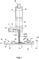
- Figure 1 schematically shows the possible formation of splashes or splatters SP while pouring a chemically reactive polymeric mixture, on an impact surface of an open moulding cavity of an object, or mould, by a high pressure mixing device 10, for example of the so called "L" type disclosed in US 4332335 , or of the linear type disclosed in US 4096585 .
- the device 10 comprises a mixing chamber 11 having a diameter D1, oriented orthogonally with respect to a pouring duct 12 having an inner diameter D2, as further described referring to the following Figures 9-12 .
- a first injector 13 ( Figure 11 ) supplies into the mixing chamber 11, a high kinetic energy jet of a first liquid component A, while a second injector 14 supplies into the mixing chamber 11 a respective and simultaneous high kinetic energy jet of a second liquid component B, suitable for forming a chemically reactive polymeric mixture or a polymeric resin of the previously defined type.
- the jets of the liquid components A and B hit frontally and/or against the walls of the mixing chamber 11 with a high turbulence and kinetic energy, thoroughly mixing and resulting into a liquid mixture of a chemically reactive polymeric resin; the reactive mixture flowing into the pouring duct 12 fills it during a first initial transitional step and flows out with a flow F having a specific flowrate Q, and a specific speed V related to the flowrates of the single polymeric components A, B, the rheological characteristics of the reactive mixture, as well as the cross section of the pouring duct 12 of the specific mixing device 10 employed.
- valve member 15 Inside the mixing chamber 11 slides a valve member 15 that is operatively connected to the piston 17' of a control hydraulic cylinder 17.
- the valve member 15 as will be hereinafter described and shown in Figures 10 and 11 , is configured with longitudinal-slots 15', 15" which, in the advanced position of the valve member 15 in which closes the mixing chamber 11, determine the recirculation of the chemical components A and B towards respective storage tanks, not shown in Figure 1 , and indicated by 35A and 35B in Figure 13 ; and also to eject in the pouring duct 12 the reactive mixture which remains in the mixing chamber 11 at the end of each operative cycle, by advancement of the valve member 15, as hereinafter described.
- the flow F of liquid reactive mixture flowing out from the pouring duct 12 with a certain flowrate Q and speed V impacts in a prefixed zone or point P, against an impact surface 18 of an open moulding cavity 19 of a containment shell for the reactive mixture, or of a mould 20.
- the flow F of reactive mixture, directed towards the impact surface 18 of the moulding cavity 19, may impact orthogonally against said surface 18, as shown, or with a tangential component of the speed of the flow F, resulting from tilting the pouring duct 12, i.e. as a consequence of a relative movement between the mixing device 10 and the surface 18 of the moulding cavity 19.
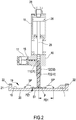
- Figure 2 shows the same mixing device 10 of Figure 1 , in a pouring condition of the reactive mixture, according to the method of the present invention, which will be further described referring to the following Figures.
- cohesive flow means that, once the reactive mixture has initially filled the pouring duct 12, as shown in Figure 2 , the exiting flow F does not have vein separations, though it can have swellings on the surface or waves indicative of movements inside the same flow, which are characterized by inner movements and speed that are substantially parallel to the flow F trajectory.
- laminatear flow means a condition that is free from inner motions, characterized by speeds parallel to the direction of the flow.
- the flow F of reactive polymeric mixture outcoming the pouring duct 12 in the three previously defined pouring steps, as assessed by experimental tests carried out starting at a high speed, impacts in P against the surface 18 of the moulding cavity 19 under conditions and in ways that may depend on one or more of the following elements, separately or in combination:
- the flow F of mixture may result in spatters SP in form of drops and/or filaments which can bounce even far from the impact zone P, in at all accidental directions, in case flowrate Q and impact speed V of the flow F are too high.
- the first step “a" of the initial transitional pouring step of-the mixture is followed by the second transitional step “b"; in this second transitional step the flow F of reactive mixture starts filling the pouring duct 12; however the outcoming flow F may be non-laminar and characterized by some accidental waves or rotations.
- spatters SP of the reactive mixture may not form, or may spread with a restrained flight distance FD1, which is limited with respect to the peripheral edge 21 and other specific zone of the moulding cavity 19 of the mould 20, product or containment shell of the reactive mixture for producing an object or a moulded piece.
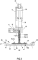
- the pool of mixture PZ2 takes on an elongated ovoidal shape in the flow direction F; in this case minimum width of the pool PZ2 means the diameter of an ideal circle of the peripheral peak, as measured orthogonally to the flow F direction.
- the pool PZ2 of reactive mixture with raised peripheral edge in form of a wave front which is formed during the third pouring step "c", tends to dampen the radial component of the flow F impacting and enlarging on the surface 18, preventing or limiting splash or spatter formation or spreading thereof on the aforesaid specific zones of the moulding cavity; spatter formation SP is inhibited or limited by the pool PZ2 even for flowrate Q2 values, at regime operative conditions, that are comparatively much higher than the value Q1 of the pouring flowrate during the initial transitional step, as far as the flow F of mixture is cohesive or in laminar conditions.
- the method provides pouring a flow F of a chemically reactive polymeric mixture resulting from a first component A and at least a second component B, with flowrates Q and speeds V close to a condition of forming spatters of mixture SP that can fly near, and not beyond the peripheral edge 21 or other specific zone of an open moulding cavity 19 configured with an impact surface 18, by a high pressure mixing device 10 comprising a mixing chamber 11 having a diameter D1, which communicates with a pouring duct 12 configured with an inner diameter D2; wherein the flow F of reactive mixture is oriented orthogonally or slanted towards and against an impact zone P of the surface 18 of the moulding cavity 19, wherein the method comprises the steps of:
- the method provides maintaining, for the reactive mixture flowing out of the pouring duct 12 with inner diameter D2, cohesive flow FP conditions, in which conditions said reactive mixture, once initially filled in said pouring duct 12, flows out of said pouring duct 12 without vein separations, with possible inner motions transversal to the flow but contained within the jet with the veins substantially parallel to the flow F trajectory, or it flows out in a laminar flow condition, without inner motions traversal to the flow and with speeds parallel to the direction of said flow F.
- the flowrate Q and speed V values of the flow poured F during the initial transitional step may be defined by experimental tests carried out by means of a conventional high pressure mixing device, operating in such a way that, both during an initial transitional step, and later on, pouring the reactive mixture occurs under a controlled condition of impact flowrate and speed and flowing on the surface 18 with no spatters of mixture SP, or spatters SP having a restrained flight distance, lower than a distance comprised between the impact zone P of the flow F and a closest point of the peripheral edge 21 of the moulding cavity or of the other above indicated zones of the moulding cavity 19.
- the curve S passing through points P1, P2, P3 and P4 was replaced by the straight line LR in the range Ad1-Ad4; the slope of the straight line LR thus corresponds to the speed coefficient C of the previous formula 1, while the point of intersection with the straight line LR for a general dimension of the cross section Ad of the pouring duct 12, allows to detect the flowrate value QX enabling pouring conditions without spatters or with spatters having a restrained flight distance, during the initial transitional step.
- intersection of the straight line LR with the axis of the flowrates Q allows instead calculating the base flowrate coefficient B resulting from the linearization, for sections of the pouring duct 12 tending towards zero.
- a high pressure mixing device 10 was used supplied with two chemically reactive polymeric components A and B, such as a polyol and an isocyanate, adapted to form a polyurethane mixture; however, it is not excluded that the pouring method without spatters or with spatters with a restrained flight distance, object of the present invention, may be implemented using any high pressure mixing device configured to supply one or more chemically reactive polymeric components, including a possible supply of one of the components in the axial direction of the mixing chamber, through a longitudinal hole in the sliding valve member of the mixing chamber, for instance as described in US 6079867 .
- the high pressure mixing device used during the tests comprises a base body 10 configured with a mixing chamber 11 having a diameter D1, and with a pouring duct 12 having a diameter D2 greater than the diameter D1, arranged orthogonally to the mixing chamber 11, and with nozzles 13, 14 for injecting two polymeric components A, B.
- a sliding valve member 15 operatively connected to the piston 17' of a control hydraulic cylinder 17, is axially sliding into a hole of the body 10 to be moved between a backward position, shown in Figure 11 and 12 wherein it opens the mixing chamber 11 towards the pouring duct 12, and an advanced position, shown in Figure 10 in which it closes the outlet end 11' of the mixing chamber 11 towards the pouring duct 12, ejecting into the latter the residual polymeric mixture which remains into the mixing chamber 11 at the end of each pouring operation; and in which it provides, in a known way, recycling the single components A, B by respective recirculation grooves 15', 15" which, in the advanced position of the valve member 15, place injectors 13 and 14 into communication with respective recirculation ducts 23, 24.
- the cleaning member 25 may also be moved towards the opening and stopped with its front end at a plurality of intermediate positions wherein it partially close the opening of the outlet end 11' of the mixing chamber 11.
- Figure 12 shows, for exemplary purposes, a condition wherein the cleaning member 25 of the pouring duct 12 is in an intermediate position wherein it reduces the outlet opening 11' of the mixing chamber 11, with a degree of reduction namely of restriction of the opening towards the pouring duct defined by a referred percentage value of the diameter D1 of the mixing chamber 11 itself.
- the two flowrate fields were defined by conventional tests, with partial closure degree of the outlet end 11' of the mixing chamber 11 comprised between 0% and 40%, respectively reduced between 40% and 90% of the diameter D1 of the mixing chamber 11. It was possible to define a first field of partial closure in which a poured flowrate Q 00 is set without forming mixture spatters, as previously defined, during the initial transitional pouring step, with a closure degree of the outlet 11' of the mixing chamber 11 comprised between 0% and 40%, hereinafter also referred to as "zero spatters” field; and a second field with poured flowrate Q op and with a high closure degree of the outlet end 11' of the mixing chamber 11 comprised between 40% and 90%, hereinafter also referred to as "zero spatters” field having a high closure degree.
- a third and a fourth specific flowrate field based on the section Ad of the pouring duct 12, resulting in the formation of patters during the first two initial transitional steps "a", "b", wherein the flight distance FD is lower than a reference distance such not to cause smearing of mixture at outer zones of the moulding cavity 19 or shell to be filled with foam, or specific zones of the moulding cavity - such as protruding zones or zones with gaskets and/or inserts - i.e. spatters outside the same moulding cavity.
- the reference flight distance depends on the geometrical shape and on the dimensions of the moulding cavity, and may be equal to or lower than 45% of the minimum width of the moulding cavity; for moulds suitable for foaming refrigerator doors, panels or objects similar thereto, an optimal reference distance may be comprised between 300 and 350 mm, or lower.
- a third and a fourth flowrate field at which set the mixing apparatus during the initial transitional step may be defined again by partially closing the section of the outlet end 11' of the mixing chamber 11 to a low degree between 0% and 40%, respectively to a high degree between 40% and 90%.
- the third flowrate field with a lower reduction degree i.e. comprised between 0% and 40% may be defined on the basis of formula 4:
- Q lso C 2 ⁇ Ad + B 2
- the cross section of the pouring duct 12 may be preferably comprised between 0,5 cm 2 and 8 cm 2 , it is possible to:
- Avoiding the formation of spatters of mixture or limiting the smearing distance thereof by operating at low flowrates during an initial transitional step, by forming a pool of mixture with a raised peripheral edge in form of a wave front, suitable to dampen possible spatters, is thus advantageous in terms of substantially improving the production process, reducing wastes as well as substantially reducing times for processing and maintenance and cleaning operations; once the initial transitional step is terminated it will be possible to increase the poured flowrate up until a high regime of flowrate with respect to the initial transitional flowrate, which allow the best conditions for filling a mould cavity, maintaining the flow of mixture being poured in cohesive or laminar conditions; forming splatters of mixture with high flight distances, higher than a specific reference value, can therefore be prevented.
- the moulding cavity 19 According to the geometrical characteristics, shape and dimensions of the moulding cavity 19 as well as the specific pouring needs of the resulting reactive mixture, it is possible to maintain the high pressure mixing device 10 in a fixed position with respect to the moulding cavity 19, or to generate a relative movement between the mixing device 10 and the impact surface 18 of the moulding cavity 19; this can be for instance obtained by moving the mixing device 10 with respect to the surface 18 of the moulding cavity 19, or vice versa moving the surface 18 of the moulding cavity 19 with respect to the mixing device 10 based on specific kinematic data.
- FIG 13 a control electronic unit CU of a dosing apparatus and high pressure mixing device of a chemically reactive component A and of at least one further chemically reactive component B suitable for forming a polymeric resin of the type initially indicated, is shown.
- the control unit CU is also operatively connected to flow transducers FTA and FTB downstream of the respective dosing pumps PA, PB.
- a first recirculation circuit RCA and RCB allows to recirculate by means of recirculating grooves15', 15" of the valve member 15 ( Figure 10 ), the single chemical components A, B kept under pressure and poured through the injectors 13 and 14, when the sliding valve member 15 is in the advanced or closed position of Figure 10 , while the second recirculation circuit RC1, RC2 comprising the respective valves VA, VB allows to recirculate the single components A and B outside the injectors 13 and 14 at a pressure lower than the previous one, during a time lapse comprised between a step of pouring the resulting reactive mixture, and the subsequent pouring step.
- auxiliary controllers CA respectively CB consisting in functional blocks controlling the flowrates QA, QB of the single components A, B to be mixed, in the time ranges T0-T1, T1-T2 and following ones
- the unit CU is programmable with auxiliary control functions of the flowrates QA and QB, control means of
- the control unit CU also handles commands and opening and closing sequences of the members of the high pressure mixing apparatus 10, and of the parts composing the dosing apparatus, as well as the steps of recirculation of the single components A, B.
- control means of the auxiliary functions of the unit CU, or the single auxiliary controllers CA, CB are programmed to allow supplying the single polymeric components A and at least B with programmed supply flowrates QA1, QA2 and QB1, QB2, according to a mixing ratio R, depending on the reactive mixture flowrates set in the main controller CM, between the minimum value QA1, QB1 and a maximum value QA2, QB2 in flow conditions (F) of the liquid reactive mixture, without spatters or with spatters having a restrained flight distance, during the previously defined time ranges.
- a mixing ratio R depending on the reactive mixture flowrates set in the main controller CM, between the minimum value QA1, QB1 and a maximum value QA2, QB2 in flow conditions (F) of the liquid reactive mixture, without spatters or with spatters having a restrained flight distance, during the previously defined time ranges.
- the controller CA or the auxiliary control function of the unit CU outputs a reference signal REFA of the flowrate of the component A, that varies over time and increases according to a law that is pre-set and duly programmed in the control unit; in the specific case the auxiliary controller CA provides simultaneously a further output signal FFA called "feed-forward", that varies over time depending on the same law, suitable to allow for the offset of possible delays in actuating the controlled system, which anticipates the control command of the motor or actuator MA, such to minimise the tracking movement.
- the at least additional auxiliary controller CB or control function of the control unit CU provides a reference output signal REFB of the flowrate of the at least further chemical reactive component B suitable for forming a polymeric resin, which varies over time according to a pre-set law proportional to that of the reactive chemical component A suitable for forming the polymeric resin, according to the stoichiometric ratio R between the two or more components, duly provided and programmed in the control unit CU, and similarly and simultaneously a further "feed-forward" output signal FFB, variable over time depending on the same law, suitable for allowing the offset of possible delays in actuating the controlled system, anticipating the control command of the motor or actuator MB, such to minimise the tracking error.
- REFB reference output signal
- a first comparison node N1A From the flowrate reference signal REFA provided by the controller CA, in a first comparison node N1A, it is deducted the feedback signal FRA of the measure of the real flowrate QA of the component A, detected by means of a proper flowrate measuring device consisting of the flow transducer FTA and duly conditioned and digitalised for instance by a pulse/frequency converter 36A, signal corresponding to the flowrate sent from the pump PA to the corresponding injector 13 of the mixing device 10.
- the ERRA signal deriving from the deduction comparison between REFA and FRA in the comparison node N1A is in turn summed in a second node N2A with the advance or feed-forward control signal FFA provided by the controller CA or by the control function of the unit CU, which corresponds to the flowrate that varies over time of the component A to be poured by the pump PA and which takes into account also actuation errors or delays that can occur during the transitional steps for example of a small flowrate percentage that can accumulate in the tubes due to the elasticity thereof, and also of the acceleration delays that the frequency variator system and electric motor introduce due to the torque increase to be provided by the motor.
- the signal RVA deriving from the sum comparison between the ERRA and FFA signals in the second node N2A is duly converted into a frequency reference and sent for instance to the command input of the frequency converter or inverter 37A which commands and controls the revolution speed of the electric motor MA when the latter is of the alternating current type; or it may be converted into a speed reference signal for actuating for example a direct current motor, or a brushless motor, as the motors are already provided with a revolution speed detector for direct current motors and of rotational angle and relative speed for brushless motors, whose actuation are already provided.
- the further at least controller CB or control function of the control unit CU provides to convert the frequency reference signal RVB for the frequency converter 37B of the alternating current motor MB associated to the pump PB of the reactive chemical component B suitable to form the polymeric resin, or the speed reference signal of the direct current or brushless motor or motors associated to the pumps of the other polymeric components, keeping them proportional according to the respective stoichiometric ratio of the component A.
- the at least two polymeric components A, B are supplied in a metered and controlled way according to the previously described diagram, in a stoichiometric ratio, towards the respective injectors 13, 14 which adjust the pressure on the delivery line of the pump PA, PB and transform the pressure energy into the kinetic energy of the jets.
- the components A, B or possibly other components, are recirculated towards respective tanks 35A and 35B keeping the components A, B separate when the valve member 15 of the mixing device 10 are in the advanced or closed position.
- the valve member 15 is moved backwards opening the mixing chamber 11, the two or more jets collide one against the other and against the walls inside mixing chamber 11 thoroughly mixing due to the high turbulence resulting from the jet collision, forming the reacting mixture which flows out of the pouring duct 12 through the opening 11' of the mixing chamber 11.
- the turbulence of the mixture is reduced also thanks to the proper setting of the restriction of the opening 11' of the mixing chamber 11, caused by the front end of the self-cleaning member 25 stopped at the opening, such to reduce the outlet 11' from the mixing chamber 11 of a preset value.
- the reacting mixture then flows out through the pouring duct 12 to be poured in the described modes on the surface 18 of the open moulding cavity 19.
- control functional blocks indicating the controllers CA, CB or control functions of the unit CU, in the example taken into consideration show a graph of the variation of flowrates QA and at least QB of the two polymeric components A and B, and consequently of the flowrate of the resulting reactive mixture QV, according to the pouring time T, consequently the variation of the speed of the jet of mixture poured on the inner surface 18 of the open moulding cavity 19.
- an operator programmes the control unit CU with the law of variation over time of the total massive flowrate of reacting mixture QV, and the total amounts which must be poured in each pouring step, with the percentage stoichiometric ratio or the massive flowrate ratio of each component A and at least B, forming the reacting mixture; the operator also programmes the amount of reacting mixture to be poured at each step, namely at the step corresponding to the initial constant flowrate transitional step, and later at the regime step, including the increasing flowrate ramp.
- a suitable user interface for instance a keyboard
- variation law of the mixture flowrate may be expressed in any suitable way, by planes, ramps or other exponential functions, or point variation of the total flowrate which the control unit CU will relate to the specific amounts to be poured in a controlled way, as described.
- the flowrates vary with increasing values depending on the ratio set in the time range set between T1 and T2, to flowrates QA2, QB2; thereafter they are kept constant or are varied in a controlled way in the time range between the instant T2 and the instant of closure of the mixing apparatus 10, such to pour the total amount of programmed mixture.
Landscapes
- Engineering & Computer Science (AREA)
- Mechanical Engineering (AREA)
- Robotics (AREA)
- Casting Or Compression Moulding Of Plastics Or The Like (AREA)
- Injection Moulding Of Plastics Or The Like (AREA)
- Processing And Handling Of Plastics And Other Materials For Molding In General (AREA)
Applications Claiming Priority (1)
| Application Number | Priority Date | Filing Date | Title |
|---|---|---|---|
| IT102019000024949A IT201900024949A1 (it) | 2019-12-20 | 2019-12-20 | Metodo e apparecchiatura per erogare una miscela polimerica priva di schizzi |
Publications (3)
| Publication Number | Publication Date |
|---|---|
| EP3838567A1 true EP3838567A1 (de) | 2021-06-23 |
| EP3838567B1 EP3838567B1 (de) | 2025-08-13 |
| EP3838567C0 EP3838567C0 (de) | 2025-08-13 |
Family
ID=70228512
Family Applications (1)
| Application Number | Title | Priority Date | Filing Date |
|---|---|---|---|
| EP20215835.8A Active EP3838567B1 (de) | 2019-12-20 | 2020-12-18 | Verfahren und vorrichtung zum giessen einer spritzerfreien polymermischung |
Country Status (3)
| Country | Link |
|---|---|
| EP (1) | EP3838567B1 (de) |
| CN (1) | CN113001866B (de) |
| IT (1) | IT201900024949A1 (de) |
Families Citing this family (2)
| Publication number | Priority date | Publication date | Assignee | Title |
|---|---|---|---|---|
| CN113878785B (zh) * | 2021-10-11 | 2024-03-19 | 长虹美菱股份有限公司 | 一种注料枪头及具有其的冰箱柜聚氨酯注料系统 |
| CN114770851B (zh) * | 2022-04-12 | 2024-02-06 | 长虹美菱股份有限公司 | 一种冰箱门体的发泡注料方法 |
Citations (10)
| Publication number | Priority date | Publication date | Assignee | Title |
|---|---|---|---|---|
| US3975128A (en) | 1973-05-29 | 1976-08-17 | Krauss-Maffei Aktiengesellschaft | System for filling a mold with reactive synthetic-resin components |
| US4096585A (en) | 1976-05-17 | 1978-06-20 | Afros S.R.L. | Apparatus for mixing and ejecting interacting fluid materials |
| US4098585A (en) | 1976-06-07 | 1978-07-04 | Texaco Inc. | Amine-alkenylsuccinic acid or anhydride reaction product |
| US4175874A (en) | 1976-10-12 | 1979-11-27 | Elastogran Maschinenbau Gmbh & Co. | High pressure injection mixing head for multi-component plastics, particularly polyurethane |
| US4332335A (en) | 1978-03-09 | 1982-06-01 | Afros S.R.L. | Head for mixing and ejecting interacting liquid components, for molding plastic materials |
| EP0230921A2 (de) | 1986-01-21 | 1987-08-05 | Afros S.P.A. | Verfahren und Vorrichtung zum Schäumen von Isolationsmaterialien in Kühlanlagen und dgl. |
| US4726933A (en) | 1985-10-08 | 1988-02-23 | Admiral Equipment Company | High pressure mixing head and reactive component injection valve |
| US4966466A (en) | 1987-11-10 | 1990-10-30 | Krauss-Maffei A.G. | Impingement mixing device with pressure controlled nozzle adjustment |
| US6079867A (en) | 1997-05-22 | 2000-06-27 | Afros S.P.A. | Self-cleaning, mixing apparatus and method for the production of polyurethane formulations |
| EP2366525A1 (de) | 2010-03-15 | 2011-09-21 | Afros S.P.A. | Verfahren und Vorrichtung für die Zufuhr einer Polyurethanmischung in Hohlkörper |
Family Cites Families (13)
| Publication number | Priority date | Publication date | Assignee | Title |
|---|---|---|---|---|
| GB1201619A (en) * | 1966-09-13 | 1970-08-12 | Upjohn Co | Apparatus for the production of polyurethane foam |
| DE2513492C3 (de) * | 1975-03-26 | 1980-02-21 | The Upjohn Co., Kalamazoo, Mich. (V.St.A.) | Vorrichtung zum Vermischen eines flüssigen Treibmittels mit niedrigem Siedepunkt mit weiteren Komponenten zur Herstellung von Schaumstoff |
| US4440500A (en) * | 1982-06-21 | 1984-04-03 | Polyurethane Technology Of America-Martin Sweets Company, Inc. | High pressure impingement mixing apparatus |
| DE3437533A1 (de) * | 1984-10-12 | 1986-04-17 | Jakob 5212 Troisdorf Knoben | Verfahren und vorrichtung zum spritzen, giessen und/oder rohrbeschichten eines fuellstoffe enthaltenden, erhaertenden kunststoffs |
| US5163584A (en) * | 1990-12-18 | 1992-11-17 | Polyfoam Products, Inc. | Method and apparatus for mixing and dispensing foam with injected low pressure gas |
| IT1277651B1 (it) * | 1995-09-25 | 1997-11-11 | Afros Spa | Procedimento e apparecchiatura di miscelazione ad alta pressione, per la produzione di schiume poliuretaniche pre-espanse |
| GB2433928B (en) * | 2006-01-07 | 2009-10-14 | Shane Richard Wootton | Apparatus for producing material by a chemical reaction |
| JP5301225B2 (ja) * | 2007-09-20 | 2013-09-25 | 富士フイルム株式会社 | ドープ混合方法、溶液製膜方法、ドープ混合装置、及び溶液製膜設備 |
| JP5226129B2 (ja) * | 2009-04-22 | 2013-07-03 | パナソニック株式会社 | 混合吐出装置 |
| ITMI20110892A1 (it) * | 2011-05-19 | 2012-11-20 | Afros Spa | Apparecchiatura autopulente di miscelazione ad alta pressione per materiale composito |
| US20180222093A1 (en) * | 2015-08-04 | 2018-08-09 | Covestro Deutschland Ag | Casting device for applying a foaming reaction mixture |
| IT201600080835A1 (it) * | 2016-08-01 | 2018-02-01 | Cannon Spa | Metodo ed apparato per la schiumatura di un corpo cavo. |
| CN108242300B (zh) * | 2017-11-28 | 2024-04-05 | 广东福德电子有限公司 | 一种自动调速的电阻器灌砂装置 |
-
2019
- 2019-12-20 IT IT102019000024949A patent/IT201900024949A1/it unknown
-
2020
- 2020-12-18 EP EP20215835.8A patent/EP3838567B1/de active Active
- 2020-12-21 CN CN202011519644.3A patent/CN113001866B/zh active Active
Patent Citations (10)
| Publication number | Priority date | Publication date | Assignee | Title |
|---|---|---|---|---|
| US3975128A (en) | 1973-05-29 | 1976-08-17 | Krauss-Maffei Aktiengesellschaft | System for filling a mold with reactive synthetic-resin components |
| US4096585A (en) | 1976-05-17 | 1978-06-20 | Afros S.R.L. | Apparatus for mixing and ejecting interacting fluid materials |
| US4098585A (en) | 1976-06-07 | 1978-07-04 | Texaco Inc. | Amine-alkenylsuccinic acid or anhydride reaction product |
| US4175874A (en) | 1976-10-12 | 1979-11-27 | Elastogran Maschinenbau Gmbh & Co. | High pressure injection mixing head for multi-component plastics, particularly polyurethane |
| US4332335A (en) | 1978-03-09 | 1982-06-01 | Afros S.R.L. | Head for mixing and ejecting interacting liquid components, for molding plastic materials |
| US4726933A (en) | 1985-10-08 | 1988-02-23 | Admiral Equipment Company | High pressure mixing head and reactive component injection valve |
| EP0230921A2 (de) | 1986-01-21 | 1987-08-05 | Afros S.P.A. | Verfahren und Vorrichtung zum Schäumen von Isolationsmaterialien in Kühlanlagen und dgl. |
| US4966466A (en) | 1987-11-10 | 1990-10-30 | Krauss-Maffei A.G. | Impingement mixing device with pressure controlled nozzle adjustment |
| US6079867A (en) | 1997-05-22 | 2000-06-27 | Afros S.P.A. | Self-cleaning, mixing apparatus and method for the production of polyurethane formulations |
| EP2366525A1 (de) | 2010-03-15 | 2011-09-21 | Afros S.P.A. | Verfahren und Vorrichtung für die Zufuhr einer Polyurethanmischung in Hohlkörper |
Also Published As
| Publication number | Publication date |
|---|---|
| EP3838567B1 (de) | 2025-08-13 |
| IT201900024949A1 (it) | 2021-06-20 |
| CN113001866B (zh) | 2024-06-11 |
| EP3838567C0 (de) | 2025-08-13 |
| CN113001866A (zh) | 2021-06-22 |
Similar Documents
| Publication | Publication Date | Title |
|---|---|---|
| EP3838567B1 (de) | Verfahren und vorrichtung zum giessen einer spritzerfreien polymermischung | |
| EP2366525B1 (de) | Verfahren für die Zufuhr einer Polyurethanmischung in Hohlkörper | |
| CN113492482B (zh) | 用于制备和分配混合物的方法和设备 | |
| US5506607A (en) | 3-D model maker | |
| EP3278949B1 (de) | Verfahren und vorrichtung zur schäumung eines hohlkörpers | |
| US11077615B2 (en) | Three-dimensional modeling apparatus and ejection unit | |
| KR20070074493A (ko) | 화학반응에 의한 물질 제조용 장치 | |
| KR20180120771A (ko) | 점성 재료 발포 장치 및 방법 | |
| CA2471449C (en) | Tri-tilt mixing head | |
| JP2002239690A (ja) | 連続鋳造用浸漬ノズル並びに連続鋳造方法 | |
| US7306119B2 (en) | Dispensing material produced by a chemical reaction | |
| US20130289152A1 (en) | Method for producing foamed moldings | |
| WO2020236461A1 (en) | Method and apparatus for real time control of injection of structural foaming agents, colorants, and other additives | |
| US20220177290A1 (en) | Apparatus for dispensing a mixture of at least two liquid components | |
| US20250177932A1 (en) | Mixer having different diameters for applicator for producing multiple component mixture | |
| CN113370480B (zh) | 塑化装置、注射成型装置以及三维造型装置 | |
| CN2136731Y (zh) | 可顺序激励的高压混合头 | |
| CN120056340A (zh) | 材料处理装置、材料处理方法和混合物施用系统 | |
| JP2025018413A (ja) | 造形物の造形に関する物理量の推定方法 | |
| JP6993123B2 (ja) | 発泡性材料の充填装置およびその充填方法 | |
| CN121405027A (zh) | 一种灌装机用压力调节装置及其灌装方法 | |
| Lim | Flow direction when fan shaped geometry is applied in gas-assisted injection molding: 1. Flow model theory and its criteria for predicting flow directions | |
| JP2007001244A (ja) | ミキシングヘッド装置 | |
| HK1073084B (en) | Dispensing material produced by a chemical reaction | |
| JPH09262848A (ja) | 樹脂原料液の混合発泡装置 |
Legal Events
| Date | Code | Title | Description |
|---|---|---|---|
| PUAI | Public reference made under article 153(3) epc to a published international application that has entered the european phase |
Free format text: ORIGINAL CODE: 0009012 |
|
| STAA | Information on the status of an ep patent application or granted ep patent |
Free format text: STATUS: THE APPLICATION HAS BEEN PUBLISHED |
|
| AK | Designated contracting states |
Kind code of ref document: A1 Designated state(s): AL AT BE BG CH CY CZ DE DK EE ES FI FR GB GR HR HU IE IS IT LI LT LU LV MC MK MT NL NO PL PT RO RS SE SI SK SM TR |
|
| STAA | Information on the status of an ep patent application or granted ep patent |
Free format text: STATUS: REQUEST FOR EXAMINATION WAS MADE |
|
| 17P | Request for examination filed |
Effective date: 20211222 |
|
| RBV | Designated contracting states (corrected) |
Designated state(s): AL AT BE BG CH CY CZ DE DK EE ES FI FR GB GR HR HU IE IS IT LI LT LU LV MC MK MT NL NO PL PT RO RS SE SI SK SM TR |
|
| STAA | Information on the status of an ep patent application or granted ep patent |
Free format text: STATUS: EXAMINATION IS IN PROGRESS |
|
| 17Q | First examination report despatched |
Effective date: 20230802 |
|
| REG | Reference to a national code |
Ref country code: DE Ref legal event code: R079 Free format text: PREVIOUS MAIN CLASS: B29C0067240000 Ipc: B29B0007740000 Ref country code: DE Ref legal event code: R079 Ref document number: 602020056394 Country of ref document: DE Free format text: PREVIOUS MAIN CLASS: B29C0067240000 Ipc: B29B0007740000 |
|
| GRAP | Despatch of communication of intention to grant a patent |
Free format text: ORIGINAL CODE: EPIDOSNIGR1 |
|
| STAA | Information on the status of an ep patent application or granted ep patent |
Free format text: STATUS: GRANT OF PATENT IS INTENDED |
|
| RIC1 | Information provided on ipc code assigned before grant |
Ipc: B29L 31/00 20060101ALN20250324BHEP Ipc: B29K 75/00 20060101ALN20250324BHEP Ipc: B29C 67/24 20060101ALI20250324BHEP Ipc: B29C 44/40 20060101ALI20250324BHEP Ipc: B29C 44/02 20060101ALI20250324BHEP Ipc: B29C 39/24 20060101ALI20250324BHEP Ipc: B29C 31/04 20060101ALI20250324BHEP Ipc: B29B 7/76 20060101ALI20250324BHEP Ipc: B29B 7/74 20060101AFI20250324BHEP |
|
| INTG | Intention to grant announced |
Effective date: 20250403 |
|
| GRAS | Grant fee paid |
Free format text: ORIGINAL CODE: EPIDOSNIGR3 |
|
| GRAA | (expected) grant |
Free format text: ORIGINAL CODE: 0009210 |
|
| STAA | Information on the status of an ep patent application or granted ep patent |
Free format text: STATUS: THE PATENT HAS BEEN GRANTED |
|
| AK | Designated contracting states |
Kind code of ref document: B1 Designated state(s): AL AT BE BG CH CY CZ DE DK EE ES FI FR GB GR HR HU IE IS IT LI LT LU LV MC MK MT NL NO PL PT RO RS SE SI SK SM TR |
|
| REG | Reference to a national code |
Ref country code: GB Ref legal event code: FG4D |
|
| REG | Reference to a national code |
Ref country code: CH Ref legal event code: EP |
|
| REG | Reference to a national code |
Ref country code: DE Ref legal event code: R096 Ref document number: 602020056394 Country of ref document: DE |
|
| REG | Reference to a national code |
Ref country code: IE Ref legal event code: FG4D |
|
| U01 | Request for unitary effect filed |
Effective date: 20250912 |
|
| U07 | Unitary effect registered |
Designated state(s): AT BE BG DE DK EE FI FR IT LT LU LV MT NL PT RO SE SI Effective date: 20250922 |
|
| PG25 | Lapsed in a contracting state [announced via postgrant information from national office to epo] |
Ref country code: IS Free format text: LAPSE BECAUSE OF FAILURE TO SUBMIT A TRANSLATION OF THE DESCRIPTION OR TO PAY THE FEE WITHIN THE PRESCRIBED TIME-LIMIT Effective date: 20251213 |
|
| PG25 | Lapsed in a contracting state [announced via postgrant information from national office to epo] |
Ref country code: NO Free format text: LAPSE BECAUSE OF FAILURE TO SUBMIT A TRANSLATION OF THE DESCRIPTION OR TO PAY THE FEE WITHIN THE PRESCRIBED TIME-LIMIT Effective date: 20251113 |
|
| PG25 | Lapsed in a contracting state [announced via postgrant information from national office to epo] |
Ref country code: HR Free format text: LAPSE BECAUSE OF FAILURE TO SUBMIT A TRANSLATION OF THE DESCRIPTION OR TO PAY THE FEE WITHIN THE PRESCRIBED TIME-LIMIT Effective date: 20250813 |
|
| PG25 | Lapsed in a contracting state [announced via postgrant information from national office to epo] |
Ref country code: GR Free format text: LAPSE BECAUSE OF FAILURE TO SUBMIT A TRANSLATION OF THE DESCRIPTION OR TO PAY THE FEE WITHIN THE PRESCRIBED TIME-LIMIT Effective date: 20251114 |
|
| PG25 | Lapsed in a contracting state [announced via postgrant information from national office to epo] |
Ref country code: PL Free format text: LAPSE BECAUSE OF FAILURE TO SUBMIT A TRANSLATION OF THE DESCRIPTION OR TO PAY THE FEE WITHIN THE PRESCRIBED TIME-LIMIT Effective date: 20250813 |
|
| PG25 | Lapsed in a contracting state [announced via postgrant information from national office to epo] |
Ref country code: RS Free format text: LAPSE BECAUSE OF FAILURE TO SUBMIT A TRANSLATION OF THE DESCRIPTION OR TO PAY THE FEE WITHIN THE PRESCRIBED TIME-LIMIT Effective date: 20251113 |
|
| PG25 | Lapsed in a contracting state [announced via postgrant information from national office to epo] |
Ref country code: ES Free format text: LAPSE BECAUSE OF FAILURE TO SUBMIT A TRANSLATION OF THE DESCRIPTION OR TO PAY THE FEE WITHIN THE PRESCRIBED TIME-LIMIT Effective date: 20250813 |
|
| U20 | Renewal fee for the european patent with unitary effect paid |
Year of fee payment: 6 Effective date: 20251231 |
|
| PG25 | Lapsed in a contracting state [announced via postgrant information from national office to epo] |
Ref country code: SM Free format text: LAPSE BECAUSE OF FAILURE TO SUBMIT A TRANSLATION OF THE DESCRIPTION OR TO PAY THE FEE WITHIN THE PRESCRIBED TIME-LIMIT Effective date: 20250813 |
|
| PG25 | Lapsed in a contracting state [announced via postgrant information from national office to epo] |
Ref country code: CZ Free format text: LAPSE BECAUSE OF FAILURE TO SUBMIT A TRANSLATION OF THE DESCRIPTION OR TO PAY THE FEE WITHIN THE PRESCRIBED TIME-LIMIT Effective date: 20250813 |
|
| PG25 | Lapsed in a contracting state [announced via postgrant information from national office to epo] |
Ref country code: SK Free format text: LAPSE BECAUSE OF FAILURE TO SUBMIT A TRANSLATION OF THE DESCRIPTION OR TO PAY THE FEE WITHIN THE PRESCRIBED TIME-LIMIT Effective date: 20250813 |