EP3838595A1 - Verfahren zum betreiben einer rotationsdruckmaschine - Google Patents
Verfahren zum betreiben einer rotationsdruckmaschine Download PDFInfo
- Publication number
- EP3838595A1 EP3838595A1 EP19217007.4A EP19217007A EP3838595A1 EP 3838595 A1 EP3838595 A1 EP 3838595A1 EP 19217007 A EP19217007 A EP 19217007A EP 3838595 A1 EP3838595 A1 EP 3838595A1
- Authority
- EP
- European Patent Office
- Prior art keywords
- printing
- actuator
- cylinder
- disturbances
- rotary
- Prior art date
- Legal status (The legal status is an assumption and is not a legal conclusion. Google has not performed a legal analysis and makes no representation as to the accuracy of the status listed.)
- Granted
Links
Images

Classifications
-
- B—PERFORMING OPERATIONS; TRANSPORTING
- B41—PRINTING; LINING MACHINES; TYPEWRITERS; STAMPS
- B41F—PRINTING MACHINES OR PRESSES
- B41F33/00—Indicating, counting, warning, control or safety devices
-
- B—PERFORMING OPERATIONS; TRANSPORTING
- B41—PRINTING; LINING MACHINES; TYPEWRITERS; STAMPS
- B41F—PRINTING MACHINES OR PRESSES
- B41F13/00—Common details of rotary presses or machines
- B41F13/02—Conveying or guiding webs through presses or machines
-
- B—PERFORMING OPERATIONS; TRANSPORTING
- B41—PRINTING; LINING MACHINES; TYPEWRITERS; STAMPS
- B41F—PRINTING MACHINES OR PRESSES
- B41F13/00—Common details of rotary presses or machines
- B41F13/08—Cylinders
- B41F13/085—Cylinders with means for preventing or damping vibrations or shocks
-
- B—PERFORMING OPERATIONS; TRANSPORTING
- B41—PRINTING; LINING MACHINES; TYPEWRITERS; STAMPS
- B41F—PRINTING MACHINES OR PRESSES
- B41F13/00—Common details of rotary presses or machines
- B41F13/08—Cylinders
- B41F13/10—Forme cylinders
-
- B—PERFORMING OPERATIONS; TRANSPORTING
- B41—PRINTING; LINING MACHINES; TYPEWRITERS; STAMPS
- B41F—PRINTING MACHINES OR PRESSES
- B41F13/00—Common details of rotary presses or machines
- B41F13/08—Cylinders
- B41F13/24—Cylinder-tripping devices; Cylinder-impression adjustments
- B41F13/26—Arrangement of cylinder bearings
-
- B—PERFORMING OPERATIONS; TRANSPORTING
- B41—PRINTING; LINING MACHINES; TYPEWRITERS; STAMPS
- B41F—PRINTING MACHINES OR PRESSES
- B41F33/00—Indicating, counting, warning, control or safety devices
- B41F33/04—Tripping devices or stop-motions
- B41F33/14—Automatic control of tripping devices by feelers, photoelectric devices, pneumatic devices, or other detectors
-
- B—PERFORMING OPERATIONS; TRANSPORTING
- B41—PRINTING; LINING MACHINES; TYPEWRITERS; STAMPS
- B41F—PRINTING MACHINES OR PRESSES
- B41F5/00—Rotary letterpress machines
- B41F5/04—Rotary letterpress machines for printing on webs
-
- B—PERFORMING OPERATIONS; TRANSPORTING
- B41—PRINTING; LINING MACHINES; TYPEWRITERS; STAMPS
- B41F—PRINTING MACHINES OR PRESSES
- B41F5/00—Rotary letterpress machines
- B41F5/24—Rotary letterpress machines for flexographic printing
-
- F—MECHANICAL ENGINEERING; LIGHTING; HEATING; WEAPONS; BLASTING
- F16—ENGINEERING ELEMENTS AND UNITS; GENERAL MEASURES FOR PRODUCING AND MAINTAINING EFFECTIVE FUNCTIONING OF MACHINES OR INSTALLATIONS; THERMAL INSULATION IN GENERAL
- F16F—SPRINGS; SHOCK-ABSORBERS; MEANS FOR DAMPING VIBRATION
- F16F15/00—Suppression of vibrations in systems; Means or arrangements for avoiding or reducing out-of-balance forces, e.g. due to motion
- F16F15/002—Suppression of vibrations in systems; Means or arrangements for avoiding or reducing out-of-balance forces, e.g. due to motion characterised by the control method or circuitry
-
- B—PERFORMING OPERATIONS; TRANSPORTING
- B41—PRINTING; LINING MACHINES; TYPEWRITERS; STAMPS
- B41F—PRINTING MACHINES OR PRESSES
- B41F31/00—Inking arrangements or devices
- B41F31/30—Arrangements for tripping, lifting, adjusting, or removing inking rollers; Supports, bearings, or forks therefor
- B41F31/304—Arrangements for inking roller bearings, forks or supports
- B41F31/307—Sliding bearings
-
- B—PERFORMING OPERATIONS; TRANSPORTING
- B41—PRINTING; LINING MACHINES; TYPEWRITERS; STAMPS
- B41P—INDEXING SCHEME RELATING TO PRINTING, LINING MACHINES, TYPEWRITERS, AND TO STAMPS
- B41P2233/00—Arrangements for the operation of printing presses
Definitions
- the invention relates to a method having the features of the preamble of claim 1.
- the invention lies in the technical field of the graphics industry and there in particular in the field of operating a rotary printing machine, preferably for flexographic printing.
- the invention is in the subfield of controlling or regulating the machine or its drives in order to avoid or reduce disturbances
- disturbances which reduce the print quality can occur, for example so-called "bouncing" in flexographic printing. This is caused, for example, by vibrations in printing cylinders.
- the vibrations in turn, can be caused by the print image or the arrangement of printing and non-printing areas of the flexographic printing plates.
- a known but unsatisfactory measure for avoiding "bouncing" is to change the print image by additional - actually not desired - printing or non-printing locations.
- Another known but also unsatisfactory measure - because it produces too much waste - is to change the printing speed, since "bouncing" only occurs at certain printing speeds as a result of resonances. Such changes are usually made by a machine operator.
- the DE102005012915A1 discloses a method for operating a rotary printing press with rotating components, with the aim of avoiding vibrations which produce disruptive strips on the web. It is proposed to arrange a sensor on the journal of the rotating component, which sensor detects the vibrations.
- the DE10107135A1 discloses a web printing machine, for example a flexographic printing machine, and a method for vibration damping. It is proposed to arrange a detection device as a sensor on a bearing block for a printing cylinder.
- a method according to the invention for operating a rotary printing press, wherein faults in a rotating printing cylinder are detected and reduced by changing the printing speed, is characterized in that the faults are detected on an actuator of the printing cylinder.
- the invention makes it possible in an advantageous manner to print inexpensively and without disruption.
- faults are not detected on a purely mechanical component, e.g. on the pressure cylinder journal or on its bearing block, but on a - preferably electric - actuator of the pressure cylinder.
- Additional and expensive sensors on purely mechanical components are therefore not required.
- the actuator can advantageously be used as a sensor or for detecting malfunctions.
- an electrical component of the actuating drive can advantageously be accessed, particularly preferably a transmitter of the actuating drive. Additional sensors do not need to be installed and corresponding costs can be avoided.
- a further development can be characterized in that the malfunctions are detected directly on the actuator of the pressure cylinder, e.g. on this or its lines or contacts.
- a further development can be characterized in that the actuator is provided as a rotary drive with an electric motor.
- a further development can be characterized in that the actuator is provided as a rotary drive with a servomotor.
- a further development can be distinguished by the fact that the malfunctions on the servomotor are recorded.
- a further development can be characterized in that the malfunctions are detected on a transmitter of the servomotor, e.g. on this or its lines or contacts.
- the encoder can be used to control or regulate the motor.
- a further development can be characterized in that the encoder is provided as a rotary encoder.
- a further development can be characterized in that the encoder is provided as a rotary encoder.
- a further development can be characterized in that the encoder is provided as an incremental encoder.
- a further development can be characterized in that the transmitter is provided as a current transmitter.
- a further development can be characterized in that the transmitter is provided as an encoder which provides output signals.
- a further development can be distinguished by the fact that the disturbances are recorded via the current consumption of the servomotor, in particular via changes in the current consumption.
- a further development can be characterized in that the output signals of the encoder and / or the changes in the current consumption are examined for vibrations.
- a further development can be characterized in that the examination includes a comparison between an amplitude of the vibrations and a predetermined maximum amplitude.
- a further development can be characterized in that the examination is performed computationally using a digital computer.
- the digital computer can be wired or wirelessly connected to the transmitter, e.g. via one or more signal lines or via one or more data lines.
- a further development can be characterized in that the actuator is provided as an actuator of a device for position control for the printing cylinder.
- a further development can be characterized in that the actuator is provided as an actuator of a device for regulating the contact pressure of the pressure cylinder on an opposing cylinder.
- a further development can be characterized in that the device for position control is activated while the disturbances are being detected.
- a further development can be characterized by the fact that the actuator is unbraked at least while the malfunctions are being detected, e.g. by releasing a holding brake on the actuator.
- a further development can be characterized in that the device for position control is provided comprising a spindle for adjusting the position of the printing cylinder in a straight line, in particular for adjusting the position relative to an associated impression cylinder.
- a further development can be characterized in that the device for position control is provided comprising a ball screw spindle.
- a further development can be characterized in that the device for position control is provided on a drive side of the rotary printing press.
- a further development can be characterized in that the device for position control is provided on an operating side of the rotary printing press.
- a further development can be characterized in that a respective device for position control is provided on a drive side and an operating side of the rotary printing press.
- the faults can be recorded on one side (on one actuator) or on both sides (on a total of two actuators).
- a further development can be characterized in that the printing speed is changed, preferably by changing the rotational speed of the printing cylinder.
- a further development can be characterized in that the web transport speed is changed, preferably by changing the speed of the printing cylinder or by changing the speed of web tension rollers.
- a further development can be characterized in that further disturbances dependent on the printing speed of the rotary printing press of at least one rotating further printing cylinder are detected on an actuator of the further printing cylinder and that the disturbances and the further disturbances are reduced by changing the printing speed of the rotary printing press.
- a further development can be characterized by the fact that both disturbances are reduced together.
- a further development can be characterized in that the printing speed of the rotary printing press is reduced or increased until both disturbances are reduced below a predetermined maximum disturbance value.
- a further development can be characterized in that the reduction or increase in the printing speed of the rotary printing press takes place in steps.
- a further development can be characterized in that the printing cylinders are provided as flexographic printing cylinders.
- a further development can be characterized in that an anilox roller is employed on each of the printing cylinders.
- a further development can be characterized in that the printing cylinders are provided in a respective flexographic printing unit.
- a further development can be characterized in that the flexographic printing units are provided in a web-processing flexographic printing machine.
- That the disturbances are dependent on the mechanical natural frequency of the rotary printing press or its printing units or its printing cylinders.
- a further development can be characterized in that the disturbances are dependent on the printing speed of the rotary printing press.
- a further development can be characterized in that the disturbances are dependent on the print image of a printing form recorded on the printing cylinder.
- a further development can be characterized in that the disturbances cause vibrations in the printing cylinder.
- Figure 1 shows an example of a web-processing flexographic printing machine 1 when carrying out a preferred embodiment of the method according to the invention.
- the machine 1 is installed in series and has two long sides: a drive side 1a and an operating side 1b opposite it.
- the machine processes or prints a printing material web 2, preferably made of paper, cardboard, cardboard, foil or composite material.
- the web can be provided by means of a roll unwinder.
- the machine comprises several, preferably successive, printing units 3. Each printing unit includes at least one motor 4 for driving the printing unit or at least one cylinder of the printing unit during printing. After printing, the web can be further processed, e.g. punched
- the machine 1 comprises several printing cylinders 5 and 21, in particular flexographic printing cylinders, and associated impression cylinders 6 and anilox rollers 7 (see also FIG. 6).
- a printing forme 8 (a so-called cliché) with a print image 9 composed of printing and non-printing areas is received on each printing cylinder, in particular a flexographic printing plate with raised, printing areas.
- the machine 1 also includes a digital computer 23. Connections for the exchange of signals and data with the machine or its components such as the motors 4 or actuators 16 are present, but not shown for the sake of clarity.
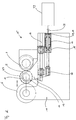
- Figure 2 shows a device for regulating 15 when carrying out a preferred embodiment of the method according to the invention.
- the impression cylinder 6 is received on at least one side (drive side 1a or AS or operating side 1b or BS) in a frame 10 of the machine 1; the Pressure cylinder 5 with its pin 11 in a bearing 12 of a bearing block 13.
- the bearing block can be displaced relative to the frame, preferably horizontally.
- a guide 14 is provided for this purpose.
- the device 15 for regulating AS and / or BS, preferably for regulating the position of the printing cylinder 5 and / or preferably for regulating the contact force between the printing cylinder 5 and the impression cylinder 6.
- the device comprises an actuator 16, preferably an electric motor 17, in particular preferably a servomotor 17 which comprises an encoder 18.
- the encoder 18 can be an encoder 19 or comprise an encoder 19.
- a spindle 20, preferably a ball screw spindle, is coupled or attached to the actuating drive 16 and, in cooperation with the guide 14, converts the rotary movement of the servomotor into a linear movement of the bearing block 13.
- the digital computer 23 is connected to the servomotor 16 and in particular to its transmitter 18 and / or encoder 19.
- the digital computer can control or regulate the rotary movements of the servomotor. In this way, the position and / or the pressing force of the pressure cylinder 5 on the impression cylinder 6 can be regulated.
- Elevations of the cliché 8 can lead to disturbances and in particular vibrations of the printing cylinder (so-called "bouncing") and thus to disturbances of the print image during the rotation of the printing cylinder 5.
- Such disturbances can be detected on the actuator 16, on the electric motor 17 or on the encoder 18, since the disturbances / vibrations are transmitted or react to the actuator and its components via the bearing block 13 and the spindle 20.
- Corresponding (current or voltage) signals or data can be picked up at the transmitter and transmitted to the digital computer 23. These can be evaluated in the digital computer.
- the disruptions can be identified by computer and measures can be taken to reduce them.
- the digital computer can control the motor 4 of the associated printing unit 3 or all motors 4 of all printing units in such a way that the disturbances / vibrations are reduced or compensated.
- the printing speed can be changed, for example increased or decreased.
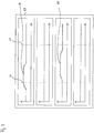
- Figure 3 shows selected steps of a preferred embodiment of the method according to the invention.
- the digital computer 23 is shown schematically, which monitors the exemplary four printing units and in the process examines or analyzes the disturbances by computer technology and thereby compensates, reduces or prevents them.
- a diagram is shown for each printing unit (from top to bottom: first to fourth printing unit), the amplitude of a disturbance being shown over the printing speed.
- a malfunction 24 occurs depending on the printing speed on a first printing unit and a further malfunction 25 occurs on a further, for example third printing unit.
- These malfunctions are recognized by the digital computer 23 at the respective printing speeds.
- the detection can take place by comparing the amplitude with a predetermined threshold value. If, for example, a fault is detected at a first printing speed 27, the printing speed can be changed until there is no fault at a second printing speed, neither on the first printing unit nor on another.
- the machine 1 is then operated at this second printing speed. In other words: the printing speed is increased (or decreased), for example, until there are no faults in any of the printing units.
Landscapes
- Engineering & Computer Science (AREA)
- Mechanical Engineering (AREA)
- General Engineering & Computer Science (AREA)
- Physics & Mathematics (AREA)
- Acoustics & Sound (AREA)
- Aviation & Aerospace Engineering (AREA)
- Inking, Control Or Cleaning Of Printing Machines (AREA)
- Rotary Presses (AREA)
Abstract
Description
- Die Erfindung betrifft ein Verfahren mit den Merkmalen des Oberbegriffs von Anspruch 1.
- Die Erfindung liegt auf dem technischen Gebiet der grafischen Industrie und dort insbesondere im Bereich des Betreibens einer Rotationsdruckmaschine, bevorzugt für den Flexodruck. Im Besonderen liegt die Erfindung dabei auf dem Teilgebiet des Steuerns oder Regelns der Maschine bzw. deren Antrieben zum Vermeiden oder Reduzieren von Störungen
- Beim Betreiben von bahnverarbeitenden Rotationsdruckmaschinen können die Druckqualität verringernde Störungen auftreten, beispielsweise so genanntes "Bouncing" beim Flexodruck. Dieses wird z.B. durch Schwingungen von Druckzylindern hervorgerufen. Die Schwingungen wiederum können durch das Druckbild bzw. die Anordnung von druckenden und nichtdruckenden Stellen der Flexodruckformen hervorgerufen werden.
- Eine bekannte aber nicht zufriedenstellende Maßnahme zum Vermeiden von "Bouncing" ist, das Druckbild durch zusätzliche - eigentlich nicht gewünschte - druckende oder nichtdruckende Stellen zu verändern. Eine weitere bekannte aber ebenfalls nicht zufriedenstellende - weil zu viel Makulatur erzeugende - Maßnahme ist, die Druckgeschwindigkeit zu ändern, da das "Bouncing" nur bei bestimmten Druckgeschwindigkeiten infolge von Resonanzen auftritt. Solche Änderungen nimmt üblicherweise ein Maschinenbediener vor.
- Eine weitere bekannte aber ebenfalls nicht zufriedenstellende - weil teure Maßnahme - ist, Beschleunigungssensoren vorzusehen, welche die Schwingungen erfassen und automatisch eine Änderung der Druckgeschwindigkeiten zu bewirken. Die
DE102005012915A1 offenbart ein Verfahren zum Betrieb einer Rotationsdruckmaschine mit rotierenden Bauteilen, wobei - störende Streifen auf der Bahn erzeugende - Schwingungen vermieden werden sollen. Es wird vorgeschlagen, einen Sensor am Zapfen des rotierenden Bauteils anzuordnen, welcher die Schwingungen erfasst. DieDE10107135A1 offenbart eine Rollendruckmaschine, z.B. eine Flexodruckmaschine, sowie ein Verfahren zur Schwingungsdämpfung. Es wird vorgeschlagen, eine Erfassungseinrichtung als Sensor an einem Lagerbock für einen Druckzylinder anzuordnen. - Es ist daher eine Aufgabe der vorliegenden Erfindung, eine Verbesserung gegenüber dem Stand der Technik zu schaffen, welche es insbesondere ermöglicht, kostengünstig und störungsfrei zu drucken.
- Diese Aufgabe wird erfindungsgemäß durch ein Verfahren nach Anspruch 1 gelöst.
- Vorteilhafte und daher bevorzugte Weiterbildungen der Erfindung ergeben sich aus den Unteransprüchen sowie aus der Beschreibung und den Zeichnungen.
- Ein erfindungsgemäßes Verfahren zum Betreiben einer Rotationsdruckmaschine, wobei Störungen eines rotierenden Druckzylinders erfasst und durch Ändern der Druckgeschwindigkeit reduziert werden, zeichnet sich dadurch aus, dass die Störungen an einem Stellantrieb des Druckzylinders erfasst werden.
- Die Erfindung ermöglicht es in vorteilhafter Weise, kostengünstig und störungsfrei zu drucken. Erfindungsgemäß werden Störungen nicht an einem rein mechanischen Bauteil erfasst, z.B. am Druckzylinderzapfen oder an dessen Lagerbock, sondern an einem - bevorzugt elektrischen - Stellantrieb des Druckzylinders. Zusätzliche und teure Sensoren an rein mechanischen Bauteilen sind daher nicht erforderlich. Der Stellantrieb kann in vorteilhafter Weise bevorzugt als Sensor bzw. für das Erfassen von Störungen verwendet werden. Hierzu kann in vorteilhafter Weise bevorzugt auf eine elektrische Komponente des Stellantriebs zugegriffen werden, besonders bevorzugt auf einen Geber des Stellantriebs. Zusätzliche Sensoren brauchen nicht verbaut zu werden und entsprechende Kosten können vermieden werden.
- Im Folgenden werden bevorzugte Weiterbildung der Erfindung (kurz: Weiterbildungen) beschrieben.
- Eine Weiterbildung kann sich dadurch auszeichnen, dass die Störungen direkt an dem Stellantrieb des Druckzylinders erfasst werden, z.B. an diesem oder dessen Leitungen oder Kontakten abgegriffen werden.
- Eine Weiterbildung kann sich dadurch auszeichnen, dass der Stellantrieb als ein Drehantrieb mit einem Elektromotor bereitgestellt wird.
- Eine Weiterbildung kann sich dadurch auszeichnen, dass der Stellantrieb als ein Drehantrieb mit einem Servomotor bereitgestellt wird.
- Eine Weiterbildung kann sich dadurch auszeichnen, dass die Störungen am Servomotor erfasst werden.
- Eine Weiterbildung kann sich dadurch auszeichnen, dass die Störungen an einem Geber des Servomotors erfasst werden, z.B. an diesem oder dessen Leitungen oder Kontakten abgegriffen werden. Der Geber kann der Steuerung oder Regelung des Motors dienen.
- Eine Weiterbildung kann sich dadurch auszeichnen, dass der Geber als ein Drehgeber bereitgestellt wird.
- Eine Weiterbildung kann sich dadurch auszeichnen, dass der Geber als ein Drehwinkelgeber bereitgestellt wird.
- Eine Weiterbildung kann sich dadurch auszeichnen, dass der Geber als ein Inkrementalgeber bereitgestellt wird.
- Eine Weiterbildung kann sich dadurch auszeichnen, dass der Geber als ein Stromgeber bereitgestellt wird.
- Eine Weiterbildung kann sich dadurch auszeichnen, dass der Geber als ein Encoder bereitgestellt wird, welcher Ausgangssignale bereitstellt.
- Eine Weiterbildung kann sich dadurch auszeichnen, dass die Störungen über die Stromaufnahme des Servomotors erfasst werden, insbesondere über Veränderungen der Stromaufnahme.
- Eine Weiterbildung kann sich dadurch auszeichnen, dass die Ausgangssignale des Encoders und/oder die Veränderungen der Stromaufnahme auf Schwingungen untersucht werden.
- Eine Weiterbildung kann sich dadurch auszeichnen, dass das Untersuchen einen Vergleich zwischen einer Amplitude der Schwingungen und einer vorgegebenen Maximalamplitude umfasst.
- Eine Weiterbildung kann sich dadurch auszeichnen, dass das Untersuchen rechentechnisch unter Verwendung eines Digitalrechners erfolgt. Der Digitalrechner kann mit dem Geber drahtgebunden oder drahtlos verbunden sein, z.B. über eine oder mehrere Signalleitungen oder über eine oder mehrere Datenleitungen.
- Eine Weiterbildung kann sich dadurch auszeichnen, dass der Stellantrieb als Stellantrieb einer Einrichtung zur Positionsregelung für den Druckzylinder bereitgestellt wird.
- Eine Weiterbildung kann sich dadurch auszeichnen, dass der Stellantrieb als Stellantrieb einer Einrichtung zur Regelung der Anpresskraft des Druckzylinders an einen Gegenzylinder bereitgestellt wird.
- Eine Weiterbildung kann sich dadurch auszeichnen, dass die Einrichtung zur Positionsregelung während des Erfassens der Störungen aktiviert ist.
- Eine Weiterbildung kann sich dadurch auszeichnen, dass der Stellantrieb wenigstens während des Erfassens der Störungen ungebremst ist, z.B. dadurch, dass eine Haltebremse am Stellantrieb gelöst ist.
- Eine Weiterbildung kann sich dadurch auszeichnen, dass die Einrichtung zur Positionsregelung eine Spindel zum geradlinigen Verstellen der Position des Druckzylinders umfassend bereitgestellt wird, insbesondere zum Verstellen der Position relativ zu einem zugehörigen Gegendruckzylinder.
- Eine Weiterbildung kann sich dadurch auszeichnen, dass die Einrichtung zur Positionsregelung eine Kugelgewindespindel umfassend bereitgestellt wird.
- Eine Weiterbildung kann sich dadurch auszeichnen, dass die Einrichtung zur Positionsregelung auf einer Antriebsseite der Rotationsdruckmaschine bereitgestellt wird.
- Eine Weiterbildung kann sich dadurch auszeichnen, dass die Einrichtung zur Positionsregelung auf einer Bedienseite der Rotationsdruckmaschine bereitgestellt wird.
- Eine Weiterbildung kann sich dadurch auszeichnen, dass eine jeweilige Einrichtung zur Positionsregelung auf einer Antriebsseite und Bedienseite der Rotationsdruckmaschine bereitgestellt wird. Dabei kann das Erfassen der Störungen auf einer Seite (an einem Stellantrieb) oder auf beiden Seiten (an insgesamt zwei Stellantrieben) erfolgen.
- Eine Weiterbildung kann sich dadurch auszeichnen, dass die Druckgeschwindigkeit geändert wird, bevorzugt durch Ändern der Drehzahl des Druckzylinders.
- Eine Weiterbildung kann sich dadurch auszeichnen, dass die Bahntransportgeschwindigkeit geändert wird, bevorzugt durch Ändern der Drehzahl des Druckzylinders oder durch Ändern der Drehzahl von Bahnzugwalzen.
- Eine Weiterbildung kann sich dadurch auszeichnen, dass weitere von der Druckgeschwindigkeit der Rotationsdruckmaschine abhängige Störungen wenigstens eines rotierenden weiteren Druckzylinders an einem Stellantrieb des Weiteren Druckzylinders erfasst werden und dass die Störungen und die weiteren Störungen durch Ändern der Druckgeschwindigkeit der Rotationsdruckmaschine reduziert werden.
- Eine Weiterbildung kann sich dadurch auszeichnen, dass beide Störungen gemeinsam reduziert werden.
- Eine Weiterbildung kann sich dadurch auszeichnen, dass die Druckgeschwindigkeit der Rotationsdruckmaschine verringert oder erhöht wird, bis beide Störungen unter einen vorgegebenen Störungs-Maximalwert reduziert sind.
- Eine Weiterbildung kann sich dadurch auszeichnen, dass das Verringern oder Erhöhen der Druckgeschwindigkeit der Rotationsdruckmaschine schrittweise erfolgt.
- Eine Weiterbildung kann sich dadurch auszeichnen, dass die Druckzylinder als Flexodruckzylinder bereitgestellt werden.
- Eine Weiterbildung kann sich dadurch auszeichnen, dass an den Druckzylindern jeweils eine Rasterwalze angestellt ist.
- Eine Weiterbildung kann sich dadurch auszeichnen, dass die Druckzylinder in einem jeweiligen Flexodruckwerk bereitgestellt werden.
- Eine Weiterbildung kann sich dadurch auszeichnen, dass die Flexodruckwerke in einer bahnverarbeitenden Flexodruckmaschine bereitgestellt werden.
- Dass die Störungen von der mechanischen Eigenfrequenz der Rotationsdruckmaschine oder deren Druckwerken oder deren Druckzylindern abhängig sind.
- Eine Weiterbildung kann sich dadurch auszeichnen, dass die Störungen von der Druckgeschwindigkeit der Rotationsdruckmaschine abhängig sind.
- Eine Weiterbildung kann sich dadurch auszeichnen, dass die Störungen von dem Druckbild einer auf dem Druckzylinder aufgenommenen Druckform abhängig sind.
- Eine Weiterbildung kann sich dadurch auszeichnen, dass die Störungen Schwingungen des Druckzylinders hervorrufen.
- Die Merkmale der Erfindung, der Weiterbildungen der Erfindung und der folgenden Ausführungsbeispiele zur Erfindung stellen auch in beliebiger Kombination miteinander vorteilhafte Weiterbildungen der Erfindung dar. Weiterbildungen der Erfindung können zudem die - im obigen Abschnitt "Technisches Gebiet der Erfindung" offenbarten - Einzelmerkmale oder Merkmalskombinationen aufweisen.
- Die Erfindung und eine oder mehrere der bevorzugten Weiterbildungen werden nachfolgend unter Bezug auf die Zeichnungen anhand eines bevorzugten Ausführungsbeispiels näher beschrieben. Einander entsprechende Merkmale sind in den Figuren mit denselben Bezugszeichen versehen.
- Die Zeichnungen zeigen:
- Figur 1
- Eine Maschine, ein erfindungsgemäßes Verfahren durchführend;
- Figur 2
- Eine Einrichtung, ein erfindungsgemäßes Verfahren durchführend; und
- Figur 3
- Ein erfindungsgemäßen Verfahren.
-
Figur 1 zeigt beispielhaft eine bahnverarbeitende Flexodruckmaschine 1 bei der Durchführung einer bevorzugten Ausführungsform des erfindungsgemäßen Verfahrens. - Die Maschine 1 ist in Reihenbauweise installiert und verfügt über zwei Längsseiten: eine Antriebsseite 1a und eine ihr gegenüberliegende Bedienseite 1b. Die Maschine verarbeitet bzw. bedruckt eine Bedruckstoffbahn 2, bevorzugt aus Papier, Karton, Pappe, Folie oder Verbundmaterial. Die Bahn kann mittels eines Rollenabwicklers bereitgestellt werden. Die Maschine umfasst mehrere, bevorzugt aufeinander folgende Druckwerke 3. Jedes Druckwerk umfasst wenigstens einen Motor 4 zum Antreiben des Druckwerks oder wenigstens eines Zylinders des Druckwerks während des Druckens. Die Bahn kann nach dem Bedrucken weiterverarbeitet, z.B. gestanzt werden
- Die Maschine 1 umfasst mehrere Druckzylinder 5 und 21, im Besonderen Flexodruckzylinder, und zugehörige Gegendruckzylinder 6 und Rasterwalzen 7 (vgl. auch Figur 6). Auf jedem Druckzylinder ist eine Druckform 8 (ein so genanntes Klischee) mit einem Druckbild 9 aus druckenden und nichtdruckenden Stellen aufgenommen, im Besonderen eine Flexodruckplatte mit erhabenen, druckenden Stellen.
- Bevorzugt umfasst jedes Druckwerk 3, wenigstens jedoch ein oder zwei Druckwerke, eine Einrichtung zur Regelung 15 mit einem jeweiligen Stellantrieb 16 oder 22.
- Die Maschine 1 umfasst auch einen Digitalrechner 23. Verbindungen zum Signal- der Datenaustausch mit der Maschine oder deren Komponenten wie z.B. den Motoren 4 oder Stellantrieben 16 sind vorhanden, der Übersichtlichkeit wegen aber nicht dargestellt.
-
Figur 2 zeigt eine Einrichtung zur Regelung 15 bei der Durchführung einer bevorzugten Ausfiihrungsform des erfindungsgemäßen Verfahrens. - Der Gegendruckzylinder 6 ist auf wenigstens einer Seite (Antriebsseite 1a bzw. AS oder Bedienseite 1b bzw. BS) in einem Gestell 10 der Maschine 1 aufgenommen; der Druckzylinder 5 mit seinem Zapfen 11 in einem Lager 12 eines Lagerbocks 13. Der Lagerbock ist relativ zum Gestell verschiebbar, bevorzugt horizontal. Hierzu ist eine Führung 14 vorhanden.
- Es ist eine Einrichtung 15 zur Regelung auf AS und/oder BS vorhanden, bevorzugt zur Positionsregelung für den Druckzylinder 5 und/oder bevorzugt zur Regelung der Anpresskraft zwischen Druckzylinder 5 und Gegendruckzylinder 6. Die Einrichtung umfasst einen Stellantrieb 16, bevorzugt einen Elektromotor 17, besonders bevorzugt einen Servomotor 17, welcher einen Geber 18 umfasst. Der Geber 18 kann ein Encoder 19 sein oder einen Encoder 19 umfassen. An den Stellantrieb 16 ist eine Spindel 20, bevorzugt eine Kugelgewindespindel gekoppelt oder angebracht, welche im Zusammenwirken mit der Führung 14 die Drehbewegung des Stellmotors in eine Linearbewegung des Lagerbock 13 überführt.
- Der Digitalrechner 23 ist mit dem Stellmotor 16 und insbesondere mit dessen Geber 18 und/oder Encoder 19 verbunden. Der Digitalrechner kann die Drehbewegungen des Stellmotors steuern oder regeln. Hierdurch kann die Position und/oder die Anpresskraft des Druckzylinders 5 an den Gegendruckzylinder 6 geregelt werden.
- Erhebungen des Klischees 8 können während der Rotation des Druckzylinders 5 zu Störungen und insbesondere Schwingungen des Druckzylinders (so genanntes "Bouncing") und damit zu Störungen des Druckbildes führen. Solche Störungen können am Stellantrieb 16, am Elektromotor 17 oder am Geber 18 erfasst werden, da die Störungen/Schwingungen über den Lagerbock 13 und die Spindel 20 auf den Stellantrieb und dessen Komponenten übertragen werden bzw. rückwirken. Entsprechende (Strom- oder Spannungs-) Signale oder Daten können am Geber abgegriffen werden und an den Digitalrechner 23 übermittelt werden. Diese können im Digitalrechner ausgewertet werden. Dabei können die Störungen rechentechnisch erkannt und Maßnahmen zu deren Reduktion ergriffen werden. Beispielsweise kann der Digitalrechner den Motor 4 des zugehörigen Druckwerks 3 oder alle Motoren 4 aller Druckwerke derart ansteuern, dass die Störungen/Schwingungen reduziert oder kompensiert werden. Dabei kann insbesondere die Druckgeschwindigkeit verändert werden, z.B. erhöht oder verringert.
-
Figur 3 zeigt ausgewählte Schritte einer bevorzugten Ausführungsform des erfindungsgemäßen Verfahrens. - Dargestellt ist schematisch der Digitalrechner 23, der die beispielhaften vier Druckwerke überwacht und dabei die Störungen rechentechnisch untersucht oder analysiert und dabei kompensiert, reduziert oder verhindert. Für jedes Druckwerk (von oben nach unten: erstes bis viertes Druckwerk) ist ein Diagramm dargestellt, wobei jeweils die Amplitude einer Störung über der Druckgeschwindigkeit dargestellt ist.
- Im gezeigten Beispiel kommt es druckgeschwindigkeitsabhängig an einem ersten Druckwerk zu einer Störungen 24 und an einem weiteren, z.B. dritten Druckwerk zu einer weiteren Störung 25. Diese Störungen werden vom Digitalrechner 23 bei den jeweiligen Druckgeschwindigkeiten erkannt. Das Erkennen kann durch einen Vergleich der Amplitude mit einem vorgegebenen Schwellwert erfolgen. Wird z.B. eine Störung bei einer ersten Druckgeschwindigkeit 27 erkannt, so kann die Druckgeschwindigkeit verändert werden, bis bei einer zweiten Druckgeschwindigkeit keine Störung vorliegt, weder am ersten Druckwerk noch an einem anderen. Bei dieser zweiten Druckgeschwindigkeit wird die Maschine 1 dann betrieben. Mit anderen Worten: die Druckgeschwindigkeit wird z.B. solange erhöht (oder verringert) bis an keinem Druckwerk Störungen vorliegen.
-
- 1
- Rotationsdruckmaschine
- 1a
- Antriebsseite/AS
- 1b
- Bedienseite/BS
- 2
- Bedruckstoffbahn
- 3
- Druckwerke
- 4
- Motoren
- 5
- Druckzylinder
- 6
- Gegendruckzylinder
- 7
- Rasterwalze
- 8
- Druckform/Klischee
- 9
- Druckbild
- 10
- Gestell
- 11
- Zylinderzapfen
- 12
- Lager
- 13
- Lagerbock
- 14
- Führung
- 15
- Einrichtung zur Regelung
- 16
- Stellantrieb
- 17
- Elektromotor oder Servomotor
- 18
- Geber
- 19
- Encoder
- 20
- Spindel
- 21
- Weiterer Druckzylinder
- 22
- Stellantrieb
- 23
- Digitalrechner
- 24
- Störungen
- 25
- Weitere Störungen
- 26
- Ausgangssignale
- 27
- erste Druckgeschwindigkeit
- 28
- zweite Druckgeschwindigkeit
Claims (10)
- Verfahren zum Betreiben einer Rotationsdruckmaschine, wobei Störungen eines rotierenden Druckzylinders (5) erfasst und durch Ändern der Druckgeschwindigkeit reduziert werden,
dadurch gekennzeichnet,
dass die Störungen an einem Stellantrieb (16) des Druckzylinders (5) erfasst werden. - Verfahren nach Anspruch 1,
dadurch gekennzeichnet,
dass der Stellantrieb (16) als ein Drehantrieb mit einem Servomotor (17) bereitgestellt wird. - Verfahren nach Anspruch 2,
dadurch gekennzeichnet,
dass die Störungen an einem Geber (18) des Servomotors erfasst werden. - Verfahren nach Anspruch 3,
dadurch gekennzeichnet,
dass der Geber (18) als ein Encoder (19) bereitgestellt wird, welcher Ausgangssignale (26) bereitstellt. - Verfahren nach Anspruch 4,
dadurch gekennzeichnet,
dass die Ausgangssignale (26) des Encoders (19) auf Schwingungen (27) untersucht werden. - Verfahren nach einem der vorhergehenden Ansprüche,
dadurch gekennzeichnet,
dass der Stellantrieb (16) als Stellantrieb einer Einrichtung (15) zur Positionsregelung für den Druckzylinder (5) bereitgestellt wird. - Verfahren nach einem der vorhergehenden Ansprüche,
dadurch gekennzeichnet,
dass der Stellantrieb (16) als Stellantrieb einer Einrichtung (15) zur Regelung der Anpresskraft des Druckzylinders (5) an einen Gegenzylinder (6) bereitgestellt wird. - Verfahren nach einem der vorhergehenden Ansprüche,
dadurch gekennzeichnet,
dass weitere von der Druckgeschwindigkeit der Rotationsdruckmaschine (1) abhängige Störungen wenigstens eines rotierenden weiteren Druckzylinders (21) an einem Stellantrieb (22) des weiteren Druckzylinders erfasst werden und dass die Störungen und die weiteren Störungen durch Ändern der Druckgeschwindigkeit der Rotationsdruckmaschine (1) reduziert werden. - Verfahren nach Anspruch 8,
dadurch gekennzeichnet,
dass die Druckgeschwindigkeit der Rotationsdruckmaschine (1) verringert oder erhöht wird, bis beide Störungen unter einen vorgegebenen Störungs-Maximalwert reduziert sind. - Verfahren nach einem der vorhergehenden Ansprüche,
dadurch gekennzeichnet,
dass die Störungen von dem Druckbild (9) einer auf dem Druckzylinder (5) aufgenommenen Druckform (8) abhängig sind.
Priority Applications (5)
| Application Number | Priority Date | Filing Date | Title |
|---|---|---|---|
| EP19217007.4A EP3838595B1 (de) | 2019-12-17 | 2019-12-17 | Verfahren zum betreiben einer rotationsdruckmaschine |
| DK19217007.4T DK3838595T3 (da) | 2019-12-17 | 2019-12-17 | Fremgangsmåde til at drive en rotationstrykkemaskine |
| CN202011283592.4A CN112976803A (zh) | 2019-12-17 | 2020-11-17 | 轮转印刷机的操作方法 |
| US17/119,178 US11504961B2 (en) | 2019-12-17 | 2020-12-11 | Method of operating a rotary printing press |
| JP2020208395A JP7577528B2 (ja) | 2019-12-17 | 2020-12-16 | 輪転印刷機を動作させるための方法 |
Applications Claiming Priority (1)
| Application Number | Priority Date | Filing Date | Title |
|---|---|---|---|
| EP19217007.4A EP3838595B1 (de) | 2019-12-17 | 2019-12-17 | Verfahren zum betreiben einer rotationsdruckmaschine |
Publications (2)
| Publication Number | Publication Date |
|---|---|
| EP3838595A1 true EP3838595A1 (de) | 2021-06-23 |
| EP3838595B1 EP3838595B1 (de) | 2023-04-26 |
Family
ID=68944229
Family Applications (1)
| Application Number | Title | Priority Date | Filing Date |
|---|---|---|---|
| EP19217007.4A Active EP3838595B1 (de) | 2019-12-17 | 2019-12-17 | Verfahren zum betreiben einer rotationsdruckmaschine |
Country Status (5)
| Country | Link |
|---|---|
| US (1) | US11504961B2 (de) |
| EP (1) | EP3838595B1 (de) |
| JP (1) | JP7577528B2 (de) |
| CN (1) | CN112976803A (de) |
| DK (1) | DK3838595T3 (de) |
Cited By (1)
| Publication number | Priority date | Publication date | Assignee | Title |
|---|---|---|---|---|
| EP3988308A1 (de) | 2020-10-22 | 2022-04-27 | Heidelberger Druckmaschinen AG | Verfahren zum betreiben einer flexodruckmaschine, flexodruckmaschine, system, flexodruckform und hülse für eine flexodruckform |
Families Citing this family (1)
| Publication number | Priority date | Publication date | Assignee | Title |
|---|---|---|---|---|
| CN116039234B (zh) * | 2022-12-29 | 2025-07-29 | 江苏新美亚印刷有限公司 | 一种实现标签自动化印刷的印刷设备 |
Citations (4)
| Publication number | Priority date | Publication date | Assignee | Title |
|---|---|---|---|---|
| DE10107135A1 (de) | 2001-02-15 | 2002-08-29 | Windmoeller & Hoelscher | Rollendruckmaschine sowie Verfahren zur Schwingungsdämpfung hieran |
| DE102005012915A1 (de) | 2005-03-21 | 2006-09-28 | Koenig & Bauer Ag | Verfahren zum Betrieb einer Maschine mit rotierenden Bauteilen |
| EP1820643A2 (de) * | 2006-02-16 | 2007-08-22 | Koenig & Bauer Aktiengesellschaft | Verfahren zur Schwingungsreduktion |
| EP2762314A1 (de) * | 2013-02-01 | 2014-08-06 | INOMETA GmbH & Co. KG | Rotationszylinder |
Family Cites Families (10)
| Publication number | Priority date | Publication date | Assignee | Title |
|---|---|---|---|---|
| DE102006004967A1 (de) | 2006-02-01 | 2007-08-02 | Heidelberger Druckmaschinen Ag | Verfahren zur aktiven Kompensation von Schwingungen in einer Bedruckstoff verarbeitenden Maschine und Bedruckstoff verarbeitende Maschine |
| DE102006050208A1 (de) * | 2006-10-25 | 2008-04-30 | Heidelberger Druckmaschinen Ag | Verfahren zur Kompensation schwingungsbegründeter Umfangsregisterfehler in einer Bogendruckmaschine |
| JP5209443B2 (ja) | 2008-11-04 | 2013-06-12 | 株式会社小森コーポレーション | 処理機の駆動制御方法及び駆動制御装置 |
| DE102009026494A1 (de) * | 2008-11-27 | 2010-06-10 | Koenig & Bauer Aktiengesellschaft | Verfahren zur Korrektur von Übergabepasserdifferenzen |
| US8844784B2 (en) * | 2010-06-28 | 2014-09-30 | Hewlett-Packard Development Company, L.P. | Controlling drive settings in a press |
| EP2450191B1 (de) * | 2010-11-05 | 2013-01-09 | Neopack, S.L. | Offsetdruckmaschine mit variablem Format und einem zentralen Druckzylinder |
| EP2771188B1 (de) | 2011-10-24 | 2017-05-31 | Bobst Mex Sa | Verfahren und anordnung zum einrichten einer druckmaschine |
| DK177831B1 (da) | 2013-02-18 | 2014-09-01 | Tresu As | Anti bouncing trykvalse/sleeve |
| DE102015204857A1 (de) * | 2015-03-18 | 2016-09-22 | Koenig & Bauer Ag | Verfahren zum Anpassen mindestens eines Druckbildes und/oder mindestens eines Zylinderaufzugs an eine Bedruckstoffänderung in einer Druckmaschine |
| CA3034742A1 (en) | 2016-08-23 | 2018-03-01 | B&R Industrial Automation GmbH | Method for controlling the drive of a machine |
-
2019
- 2019-12-17 EP EP19217007.4A patent/EP3838595B1/de active Active
- 2019-12-17 DK DK19217007.4T patent/DK3838595T3/da active
-
2020
- 2020-11-17 CN CN202011283592.4A patent/CN112976803A/zh active Pending
- 2020-12-11 US US17/119,178 patent/US11504961B2/en active Active
- 2020-12-16 JP JP2020208395A patent/JP7577528B2/ja active Active
Patent Citations (4)
| Publication number | Priority date | Publication date | Assignee | Title |
|---|---|---|---|---|
| DE10107135A1 (de) | 2001-02-15 | 2002-08-29 | Windmoeller & Hoelscher | Rollendruckmaschine sowie Verfahren zur Schwingungsdämpfung hieran |
| DE102005012915A1 (de) | 2005-03-21 | 2006-09-28 | Koenig & Bauer Ag | Verfahren zum Betrieb einer Maschine mit rotierenden Bauteilen |
| EP1820643A2 (de) * | 2006-02-16 | 2007-08-22 | Koenig & Bauer Aktiengesellschaft | Verfahren zur Schwingungsreduktion |
| EP2762314A1 (de) * | 2013-02-01 | 2014-08-06 | INOMETA GmbH & Co. KG | Rotationszylinder |
Cited By (3)
| Publication number | Priority date | Publication date | Assignee | Title |
|---|---|---|---|---|
| EP3988308A1 (de) | 2020-10-22 | 2022-04-27 | Heidelberger Druckmaschinen AG | Verfahren zum betreiben einer flexodruckmaschine, flexodruckmaschine, system, flexodruckform und hülse für eine flexodruckform |
| DE102021125087A1 (de) | 2020-10-22 | 2022-04-28 | Heidelberger Druckmaschinen Aktiengesellschaft | Verfahren zum Betreiben einer Flexodruckmaschine, Flexodruckmaschine, System, Flexodruckform und Hülse für eine Flexodruckform |
| US11712885B2 (en) | 2020-10-22 | 2023-08-01 | Heidelberger Druckmaschinen Ag | Method of operating a flexographic printing press, flexographic printing press, system, flexographic printing forme and a sleeve for a flexographic printing forme |
Also Published As
| Publication number | Publication date |
|---|---|
| EP3838595B1 (de) | 2023-04-26 |
| DK3838595T3 (da) | 2023-05-30 |
| JP2021094858A (ja) | 2021-06-24 |
| US11504961B2 (en) | 2022-11-22 |
| CN112976803A (zh) | 2021-06-18 |
| US20210178747A1 (en) | 2021-06-17 |
| JP7577528B2 (ja) | 2024-11-05 |
Similar Documents
| Publication | Publication Date | Title |
|---|---|---|
| EP0747214B1 (de) | Verfahren zum Steuern eines Mehrmotorenantriebs einer Druckmaschine sowie entsprechende Steuerung | |
| EP1609908B1 (de) | Verfahren zur Verminderung von Biegeschwingungen an mindestens einem rotierenden Zylinder einer Bearbeitungsmaschine und eine Bearbeitungsmaschine | |
| DE10135773A1 (de) | Verfahren und Vorrichtung zum Regeln einer Druckmaschine | |
| EP2147789B1 (de) | Verfahren zum Betreiben einer Rollendruckmaschine | |
| EP1136257B1 (de) | Verfahren zur Steuerung der Bahnspannung und Rollenrotationsoffsetdruckmaschine. | |
| EP3838595B1 (de) | Verfahren zum betreiben einer rotationsdruckmaschine | |
| DE102005019566A1 (de) | Druckmaschine und Verfahren zur Registerkorrektur | |
| EP1135256B1 (de) | Verfahren zur regelung eines registers | |
| DE10254118A1 (de) | Verfahren zum Antreiben einer drucktechnischen Maschine | |
| EP1759844B1 (de) | Verfahren zur Druckkorrektur | |
| EP1745925A2 (de) | Registerregelung | |
| EP0850761B1 (de) | Vorrichtung zur seitlichen Registeranpassung einer Materialbahn | |
| EP2782757B1 (de) | Flexodruckwerk mit kniehebelsystem | |
| DE10204322C1 (de) | Verfahren und Vorrichtung zur Verminderung von Schwingungen an rotierenden Bauteilen | |
| EP0513284A1 (de) | Registerregeleinrichtung zur überwachung von mehrfarben-druckmaschinen. | |
| DE102006014526B4 (de) | Verfahren und Vorrichtung zur Reduzierung von periodischen Drehwinkel-Lagedifferenzen | |
| DE10355122A1 (de) | Vorrichtung und Regelverfahren zur Kompensation von Regelabweichungen bei geregelten Antriebssystemen von Transport- und Bearbeitungsmaschinen, insbesondere Druckmaschinen | |
| DE102005054975A1 (de) | Registerregelung bei einer Druckmaschine | |
| EP0747215B1 (de) | Steuerung für eine Druckmaschine | |
| DE10255334A1 (de) | Verfahren und Vorrichtung zur Verminderung von Schingungen an rotierenden Bauteilen | |
| DE10132807B4 (de) | Regelungsverfahren und Regelungseinrichtung zum Betrieb von gekoppelten Antriebsachsen mit überlagerten Bewegungskomponenten | |
| DE102005030280B3 (de) | Verfahren zum Betrieb einer bahnverarbeitenden Maschine | |
| DE102006015597A1 (de) | Verfahren zur Erkennung und Vermeidung einer kritischen Drehzahl sowie eine Vorrichtung zur Vermeidung der kritischen Drehzahl | |
| EP3941747B1 (de) | Verfahren zum bestimmen einer position des gegenseitigen kontaktes zwischen einer druckwalze und mindestens einer gegenwalze einer flexodruckmaschine. | |
| DE202005008954U1 (de) | Antriebssystem |
Legal Events
| Date | Code | Title | Description |
|---|---|---|---|
| PUAI | Public reference made under article 153(3) epc to a published international application that has entered the european phase |
Free format text: ORIGINAL CODE: 0009012 |
|
| STAA | Information on the status of an ep patent application or granted ep patent |
Free format text: STATUS: THE APPLICATION HAS BEEN PUBLISHED |
|
| AK | Designated contracting states |
Kind code of ref document: A1 Designated state(s): AL AT BE BG CH CY CZ DE DK EE ES FI FR GB GR HR HU IE IS IT LI LT LU LV MC MK MT NL NO PL PT RO RS SE SI SK SM TR |
|
| STAA | Information on the status of an ep patent application or granted ep patent |
Free format text: STATUS: REQUEST FOR EXAMINATION WAS MADE |
|
| 17P | Request for examination filed |
Effective date: 20211223 |
|
| RBV | Designated contracting states (corrected) |
Designated state(s): AL AT BE BG CH CY CZ DE DK EE ES FI FR GB GR HR HU IE IS IT LI LT LU LV MC MK MT NL NO PL PT RO RS SE SI SK SM TR |
|
| GRAP | Despatch of communication of intention to grant a patent |
Free format text: ORIGINAL CODE: EPIDOSNIGR1 |
|
| STAA | Information on the status of an ep patent application or granted ep patent |
Free format text: STATUS: GRANT OF PATENT IS INTENDED |
|
| INTG | Intention to grant announced |
Effective date: 20230120 |
|
| GRAS | Grant fee paid |
Free format text: ORIGINAL CODE: EPIDOSNIGR3 |
|
| GRAA | (expected) grant |
Free format text: ORIGINAL CODE: 0009210 |
|
| STAA | Information on the status of an ep patent application or granted ep patent |
Free format text: STATUS: THE PATENT HAS BEEN GRANTED |
|
| AK | Designated contracting states |
Kind code of ref document: B1 Designated state(s): AL AT BE BG CH CY CZ DE DK EE ES FI FR GB GR HR HU IE IS IT LI LT LU LV MC MK MT NL NO PL PT RO RS SE SI SK SM TR |
|
| REG | Reference to a national code |
Ref country code: GB Ref legal event code: FG4D Free format text: NOT ENGLISH |
|
| REG | Reference to a national code |
Ref country code: CH Ref legal event code: EP |
|
| REG | Reference to a national code |
Ref country code: DE Ref legal event code: R096 Ref document number: 502019007546 Country of ref document: DE |
|
| REG | Reference to a national code |
Ref country code: AT Ref legal event code: REF Ref document number: 1562547 Country of ref document: AT Kind code of ref document: T Effective date: 20230515 |
|
| REG | Reference to a national code |
Ref country code: IE Ref legal event code: FG4D Free format text: LANGUAGE OF EP DOCUMENT: GERMAN |
|
| REG | Reference to a national code |
Ref country code: DK Ref legal event code: T3 Effective date: 20230525 |
|
| REG | Reference to a national code |
Ref country code: NL Ref legal event code: FP |
|
| P01 | Opt-out of the competence of the unified patent court (upc) registered |
Effective date: 20230517 |
|
| REG | Reference to a national code |
Ref country code: LT Ref legal event code: MG9D |
|
| PG25 | Lapsed in a contracting state [announced via postgrant information from national office to epo] |
Ref country code: SE Free format text: LAPSE BECAUSE OF FAILURE TO SUBMIT A TRANSLATION OF THE DESCRIPTION OR TO PAY THE FEE WITHIN THE PRESCRIBED TIME-LIMIT Effective date: 20230426 Ref country code: PT Free format text: LAPSE BECAUSE OF FAILURE TO SUBMIT A TRANSLATION OF THE DESCRIPTION OR TO PAY THE FEE WITHIN THE PRESCRIBED TIME-LIMIT Effective date: 20230828 Ref country code: NO Free format text: LAPSE BECAUSE OF FAILURE TO SUBMIT A TRANSLATION OF THE DESCRIPTION OR TO PAY THE FEE WITHIN THE PRESCRIBED TIME-LIMIT Effective date: 20230726 Ref country code: ES Free format text: LAPSE BECAUSE OF FAILURE TO SUBMIT A TRANSLATION OF THE DESCRIPTION OR TO PAY THE FEE WITHIN THE PRESCRIBED TIME-LIMIT Effective date: 20230426 |
|
| PG25 | Lapsed in a contracting state [announced via postgrant information from national office to epo] |
Ref country code: RS Free format text: LAPSE BECAUSE OF FAILURE TO SUBMIT A TRANSLATION OF THE DESCRIPTION OR TO PAY THE FEE WITHIN THE PRESCRIBED TIME-LIMIT Effective date: 20230426 Ref country code: PL Free format text: LAPSE BECAUSE OF FAILURE TO SUBMIT A TRANSLATION OF THE DESCRIPTION OR TO PAY THE FEE WITHIN THE PRESCRIBED TIME-LIMIT Effective date: 20230426 Ref country code: LV Free format text: LAPSE BECAUSE OF FAILURE TO SUBMIT A TRANSLATION OF THE DESCRIPTION OR TO PAY THE FEE WITHIN THE PRESCRIBED TIME-LIMIT Effective date: 20230426 Ref country code: LT Free format text: LAPSE BECAUSE OF FAILURE TO SUBMIT A TRANSLATION OF THE DESCRIPTION OR TO PAY THE FEE WITHIN THE PRESCRIBED TIME-LIMIT Effective date: 20230426 Ref country code: IS Free format text: LAPSE BECAUSE OF FAILURE TO SUBMIT A TRANSLATION OF THE DESCRIPTION OR TO PAY THE FEE WITHIN THE PRESCRIBED TIME-LIMIT Effective date: 20230826 Ref country code: HR Free format text: LAPSE BECAUSE OF FAILURE TO SUBMIT A TRANSLATION OF THE DESCRIPTION OR TO PAY THE FEE WITHIN THE PRESCRIBED TIME-LIMIT Effective date: 20230426 Ref country code: GR Free format text: LAPSE BECAUSE OF FAILURE TO SUBMIT A TRANSLATION OF THE DESCRIPTION OR TO PAY THE FEE WITHIN THE PRESCRIBED TIME-LIMIT Effective date: 20230727 |
|
| PG25 | Lapsed in a contracting state [announced via postgrant information from national office to epo] |
Ref country code: FI Free format text: LAPSE BECAUSE OF FAILURE TO SUBMIT A TRANSLATION OF THE DESCRIPTION OR TO PAY THE FEE WITHIN THE PRESCRIBED TIME-LIMIT Effective date: 20230426 |
|
| PG25 | Lapsed in a contracting state [announced via postgrant information from national office to epo] |
Ref country code: SK Free format text: LAPSE BECAUSE OF FAILURE TO SUBMIT A TRANSLATION OF THE DESCRIPTION OR TO PAY THE FEE WITHIN THE PRESCRIBED TIME-LIMIT Effective date: 20230426 |
|
| REG | Reference to a national code |
Ref country code: DE Ref legal event code: R097 Ref document number: 502019007546 Country of ref document: DE |
|
| PG25 | Lapsed in a contracting state [announced via postgrant information from national office to epo] |
Ref country code: SM Free format text: LAPSE BECAUSE OF FAILURE TO SUBMIT A TRANSLATION OF THE DESCRIPTION OR TO PAY THE FEE WITHIN THE PRESCRIBED TIME-LIMIT Effective date: 20230426 Ref country code: SK Free format text: LAPSE BECAUSE OF FAILURE TO SUBMIT A TRANSLATION OF THE DESCRIPTION OR TO PAY THE FEE WITHIN THE PRESCRIBED TIME-LIMIT Effective date: 20230426 Ref country code: RO Free format text: LAPSE BECAUSE OF FAILURE TO SUBMIT A TRANSLATION OF THE DESCRIPTION OR TO PAY THE FEE WITHIN THE PRESCRIBED TIME-LIMIT Effective date: 20230426 Ref country code: EE Free format text: LAPSE BECAUSE OF FAILURE TO SUBMIT A TRANSLATION OF THE DESCRIPTION OR TO PAY THE FEE WITHIN THE PRESCRIBED TIME-LIMIT Effective date: 20230426 Ref country code: CZ Free format text: LAPSE BECAUSE OF FAILURE TO SUBMIT A TRANSLATION OF THE DESCRIPTION OR TO PAY THE FEE WITHIN THE PRESCRIBED TIME-LIMIT Effective date: 20230426 |
|
| PLBE | No opposition filed within time limit |
Free format text: ORIGINAL CODE: 0009261 |
|
| STAA | Information on the status of an ep patent application or granted ep patent |
Free format text: STATUS: NO OPPOSITION FILED WITHIN TIME LIMIT |
|
| 26N | No opposition filed |
Effective date: 20240129 |
|
| PG25 | Lapsed in a contracting state [announced via postgrant information from national office to epo] |
Ref country code: SI Free format text: LAPSE BECAUSE OF FAILURE TO SUBMIT A TRANSLATION OF THE DESCRIPTION OR TO PAY THE FEE WITHIN THE PRESCRIBED TIME-LIMIT Effective date: 20230426 |
|
| PG25 | Lapsed in a contracting state [announced via postgrant information from national office to epo] |
Ref country code: SI Free format text: LAPSE BECAUSE OF FAILURE TO SUBMIT A TRANSLATION OF THE DESCRIPTION OR TO PAY THE FEE WITHIN THE PRESCRIBED TIME-LIMIT Effective date: 20230426 |
|
| PG25 | Lapsed in a contracting state [announced via postgrant information from national office to epo] |
Ref country code: LU Free format text: LAPSE BECAUSE OF NON-PAYMENT OF DUE FEES Effective date: 20231217 |
|
| PG25 | Lapsed in a contracting state [announced via postgrant information from national office to epo] |
Ref country code: MC Free format text: LAPSE BECAUSE OF FAILURE TO SUBMIT A TRANSLATION OF THE DESCRIPTION OR TO PAY THE FEE WITHIN THE PRESCRIBED TIME-LIMIT Effective date: 20230426 |
|
| GBPC | Gb: european patent ceased through non-payment of renewal fee |
Effective date: 20231217 |
|
| REG | Reference to a national code |
Ref country code: BE Ref legal event code: MM Effective date: 20231231 |
|
| PG25 | Lapsed in a contracting state [announced via postgrant information from national office to epo] |
Ref country code: MC Free format text: LAPSE BECAUSE OF FAILURE TO SUBMIT A TRANSLATION OF THE DESCRIPTION OR TO PAY THE FEE WITHIN THE PRESCRIBED TIME-LIMIT Effective date: 20230426 Ref country code: LU Free format text: LAPSE BECAUSE OF NON-PAYMENT OF DUE FEES Effective date: 20231217 |
|
| REG | Reference to a national code |
Ref country code: IE Ref legal event code: MM4A |
|
| PG25 | Lapsed in a contracting state [announced via postgrant information from national office to epo] |
Ref country code: IE Free format text: LAPSE BECAUSE OF NON-PAYMENT OF DUE FEES Effective date: 20231217 |
|
| PG25 | Lapsed in a contracting state [announced via postgrant information from national office to epo] |
Ref country code: GB Free format text: LAPSE BECAUSE OF NON-PAYMENT OF DUE FEES Effective date: 20231217 |
|
| PG25 | Lapsed in a contracting state [announced via postgrant information from national office to epo] |
Ref country code: BE Free format text: LAPSE BECAUSE OF NON-PAYMENT OF DUE FEES Effective date: 20231231 |
|
| PG25 | Lapsed in a contracting state [announced via postgrant information from national office to epo] |
Ref country code: FR Free format text: LAPSE BECAUSE OF NON-PAYMENT OF DUE FEES Effective date: 20231231 |
|
| PG25 | Lapsed in a contracting state [announced via postgrant information from national office to epo] |
Ref country code: IE Free format text: LAPSE BECAUSE OF NON-PAYMENT OF DUE FEES Effective date: 20231217 Ref country code: GB Free format text: LAPSE BECAUSE OF NON-PAYMENT OF DUE FEES Effective date: 20231217 Ref country code: FR Free format text: LAPSE BECAUSE OF NON-PAYMENT OF DUE FEES Effective date: 20231231 Ref country code: BE Free format text: LAPSE BECAUSE OF NON-PAYMENT OF DUE FEES Effective date: 20231231 |
|
| PG25 | Lapsed in a contracting state [announced via postgrant information from national office to epo] |
Ref country code: BG Free format text: LAPSE BECAUSE OF FAILURE TO SUBMIT A TRANSLATION OF THE DESCRIPTION OR TO PAY THE FEE WITHIN THE PRESCRIBED TIME-LIMIT Effective date: 20230426 |
|
| PG25 | Lapsed in a contracting state [announced via postgrant information from national office to epo] |
Ref country code: BG Free format text: LAPSE BECAUSE OF FAILURE TO SUBMIT A TRANSLATION OF THE DESCRIPTION OR TO PAY THE FEE WITHIN THE PRESCRIBED TIME-LIMIT Effective date: 20230426 |
|
| PGFP | Annual fee paid to national office [announced via postgrant information from national office to epo] |
Ref country code: CH Payment date: 20250101 Year of fee payment: 6 |
|
| PG25 | Lapsed in a contracting state [announced via postgrant information from national office to epo] |
Ref country code: CY Free format text: LAPSE BECAUSE OF FAILURE TO SUBMIT A TRANSLATION OF THE DESCRIPTION OR TO PAY THE FEE WITHIN THE PRESCRIBED TIME-LIMIT; INVALID AB INITIO Effective date: 20191217 |
|
| PG25 | Lapsed in a contracting state [announced via postgrant information from national office to epo] |
Ref country code: HU Free format text: LAPSE BECAUSE OF FAILURE TO SUBMIT A TRANSLATION OF THE DESCRIPTION OR TO PAY THE FEE WITHIN THE PRESCRIBED TIME-LIMIT; INVALID AB INITIO Effective date: 20191217 |
|
| PG25 | Lapsed in a contracting state [announced via postgrant information from national office to epo] |
Ref country code: TR Free format text: LAPSE BECAUSE OF FAILURE TO SUBMIT A TRANSLATION OF THE DESCRIPTION OR TO PAY THE FEE WITHIN THE PRESCRIBED TIME-LIMIT Effective date: 20230426 |
|
| REG | Reference to a national code |
Ref country code: CH Ref legal event code: U11 Free format text: ST27 STATUS EVENT CODE: U-0-0-U10-U11 (AS PROVIDED BY THE NATIONAL OFFICE) Effective date: 20260101 |
|
| PGFP | Annual fee paid to national office [announced via postgrant information from national office to epo] |
Ref country code: DK Payment date: 20251223 Year of fee payment: 7 |
|
| PGFP | Annual fee paid to national office [announced via postgrant information from national office to epo] |
Ref country code: NL Payment date: 20251223 Year of fee payment: 7 |
|
| REG | Reference to a national code |
Ref country code: AT Ref legal event code: MM01 Ref document number: 1562547 Country of ref document: AT Kind code of ref document: T Effective date: 20241217 |
|
| PGFP | Annual fee paid to national office [announced via postgrant information from national office to epo] |
Ref country code: DE Payment date: 20251231 Year of fee payment: 7 |
|
| PG25 | Lapsed in a contracting state [announced via postgrant information from national office to epo] |
Ref country code: AT Free format text: LAPSE BECAUSE OF NON-PAYMENT OF DUE FEES Effective date: 20241217 |
|
| PGFP | Annual fee paid to national office [announced via postgrant information from national office to epo] |
Ref country code: AT Payment date: 20260410 Year of fee payment: 5 |
|
| PGFP | Annual fee paid to national office [announced via postgrant information from national office to epo] |
Ref country code: IT Payment date: 20251229 Year of fee payment: 7 |