EP3838655A1 - Boîtier pour une batterie et procédé d'introduction d'un fluide d extinction dans un tel boîtier - Google Patents
Boîtier pour une batterie et procédé d'introduction d'un fluide d extinction dans un tel boîtier Download PDFInfo
- Publication number
- EP3838655A1 EP3838655A1 EP20214265.9A EP20214265A EP3838655A1 EP 3838655 A1 EP3838655 A1 EP 3838655A1 EP 20214265 A EP20214265 A EP 20214265A EP 3838655 A1 EP3838655 A1 EP 3838655A1
- Authority
- EP
- European Patent Office
- Prior art keywords
- housing
- cover
- battery
- casing
- fire
- Prior art date
- Legal status (The legal status is an assumption and is not a legal conclusion. Google has not performed a legal analysis and makes no representation as to the accuracy of the status listed.)
- Granted
Links
Images


Classifications
-
- H—ELECTRICITY
- H01—ELECTRIC ELEMENTS
- H01M—PROCESSES OR MEANS, e.g. BATTERIES, FOR THE DIRECT CONVERSION OF CHEMICAL ENERGY INTO ELECTRICAL ENERGY
- H01M10/00—Secondary cells; Manufacture thereof
- H01M10/42—Methods or arrangements for servicing or maintenance of secondary cells or secondary half-cells
-
- B—PERFORMING OPERATIONS; TRANSPORTING
- B60—VEHICLES IN GENERAL
- B60L—PROPULSION OF ELECTRICALLY-PROPELLED VEHICLES; SUPPLYING ELECTRIC POWER FOR AUXILIARY EQUIPMENT OF ELECTRICALLY-PROPELLED VEHICLES; ELECTRODYNAMIC BRAKE SYSTEMS FOR VEHICLES IN GENERAL; MAGNETIC SUSPENSION OR LEVITATION FOR VEHICLES; MONITORING OPERATING VARIABLES OF ELECTRICALLY-PROPELLED VEHICLES; ELECTRIC SAFETY DEVICES FOR ELECTRICALLY-PROPELLED VEHICLES
- B60L3/00—Electric devices on electrically-propelled vehicles for safety purposes; Monitoring operating variables, e.g. speed, deceleration or energy consumption
-
- B—PERFORMING OPERATIONS; TRANSPORTING
- B60—VEHICLES IN GENERAL
- B60L—PROPULSION OF ELECTRICALLY-PROPELLED VEHICLES; SUPPLYING ELECTRIC POWER FOR AUXILIARY EQUIPMENT OF ELECTRICALLY-PROPELLED VEHICLES; ELECTRODYNAMIC BRAKE SYSTEMS FOR VEHICLES IN GENERAL; MAGNETIC SUSPENSION OR LEVITATION FOR VEHICLES; MONITORING OPERATING VARIABLES OF ELECTRICALLY-PROPELLED VEHICLES; ELECTRIC SAFETY DEVICES FOR ELECTRICALLY-PROPELLED VEHICLES
- B60L3/00—Electric devices on electrically-propelled vehicles for safety purposes; Monitoring operating variables, e.g. speed, deceleration or energy consumption
- B60L3/0023—Detecting, eliminating, remedying or compensating for drive train abnormalities, e.g. failures within the drive train
- B60L3/0046—Detecting, eliminating, remedying or compensating for drive train abnormalities, e.g. failures within the drive train relating to electric energy storage systems, e.g. batteries or capacitors
-
- B—PERFORMING OPERATIONS; TRANSPORTING
- B60—VEHICLES IN GENERAL
- B60L—PROPULSION OF ELECTRICALLY-PROPELLED VEHICLES; SUPPLYING ELECTRIC POWER FOR AUXILIARY EQUIPMENT OF ELECTRICALLY-PROPELLED VEHICLES; ELECTRODYNAMIC BRAKE SYSTEMS FOR VEHICLES IN GENERAL; MAGNETIC SUSPENSION OR LEVITATION FOR VEHICLES; MONITORING OPERATING VARIABLES OF ELECTRICALLY-PROPELLED VEHICLES; ELECTRIC SAFETY DEVICES FOR ELECTRICALLY-PROPELLED VEHICLES
- B60L50/00—Electric propulsion with power supplied within the vehicle
- B60L50/50—Electric propulsion with power supplied within the vehicle using propulsion power supplied by batteries or fuel cells
- B60L50/60—Electric propulsion with power supplied within the vehicle using propulsion power supplied by batteries or fuel cells using power supplied by batteries
- B60L50/64—Constructional details of batteries specially adapted for electric vehicles
-
- H—ELECTRICITY
- H01—ELECTRIC ELEMENTS
- H01M—PROCESSES OR MEANS, e.g. BATTERIES, FOR THE DIRECT CONVERSION OF CHEMICAL ENERGY INTO ELECTRICAL ENERGY
- H01M50/00—Constructional details or processes of manufacture of the non-active parts of electrochemical cells other than fuel cells, e.g. hybrid cells
- H01M50/10—Primary casings; Jackets or wrappings
- H01M50/147—Lids or covers
- H01M50/155—Lids or covers characterised by the material
- H01M50/157—Inorganic material
-
- H—ELECTRICITY
- H01—ELECTRIC ELEMENTS
- H01M—PROCESSES OR MEANS, e.g. BATTERIES, FOR THE DIRECT CONVERSION OF CHEMICAL ENERGY INTO ELECTRICAL ENERGY
- H01M50/00—Constructional details or processes of manufacture of the non-active parts of electrochemical cells other than fuel cells, e.g. hybrid cells
- H01M50/10—Primary casings; Jackets or wrappings
- H01M50/147—Lids or covers
- H01M50/166—Lids or covers characterised by the methods of assembling casings with lids
- H01M50/171—Lids or covers characterised by the methods of assembling casings with lids using adhesives or sealing agents
-
- H—ELECTRICITY
- H01—ELECTRIC ELEMENTS
- H01M—PROCESSES OR MEANS, e.g. BATTERIES, FOR THE DIRECT CONVERSION OF CHEMICAL ENERGY INTO ELECTRICAL ENERGY
- H01M50/00—Constructional details or processes of manufacture of the non-active parts of electrochemical cells other than fuel cells, e.g. hybrid cells
- H01M50/10—Primary casings; Jackets or wrappings
- H01M50/183—Sealing members
- H01M50/19—Sealing members characterised by the material
- H01M50/197—Sealing members characterised by the material having a layered structure
-
- H—ELECTRICITY
- H01—ELECTRIC ELEMENTS
- H01M—PROCESSES OR MEANS, e.g. BATTERIES, FOR THE DIRECT CONVERSION OF CHEMICAL ENERGY INTO ELECTRICAL ENERGY
- H01M50/00—Constructional details or processes of manufacture of the non-active parts of electrochemical cells other than fuel cells, e.g. hybrid cells
- H01M50/20—Mountings; Secondary casings or frames; Racks, modules or packs; Suspension devices; Shock absorbers; Transport or carrying devices; Holders
- H01M50/249—Mountings; Secondary casings or frames; Racks, modules or packs; Suspension devices; Shock absorbers; Transport or carrying devices; Holders specially adapted for aircraft or vehicles, e.g. cars or trains
-
- H—ELECTRICITY
- H01—ELECTRIC ELEMENTS
- H01M—PROCESSES OR MEANS, e.g. BATTERIES, FOR THE DIRECT CONVERSION OF CHEMICAL ENERGY INTO ELECTRICAL ENERGY
- H01M2220/00—Batteries for particular applications
- H01M2220/20—Batteries in motive systems, e.g. vehicle, ship, plane
-
- H—ELECTRICITY
- H01—ELECTRIC ELEMENTS
- H01M—PROCESSES OR MEANS, e.g. BATTERIES, FOR THE DIRECT CONVERSION OF CHEMICAL ENERGY INTO ELECTRICAL ENERGY
- H01M50/00—Constructional details or processes of manufacture of the non-active parts of electrochemical cells other than fuel cells, e.g. hybrid cells
- H01M50/10—Primary casings; Jackets or wrappings
- H01M50/116—Primary casings; Jackets or wrappings characterised by the material
- H01M50/117—Inorganic material
- H01M50/119—Metals
-
- H—ELECTRICITY
- H01—ELECTRIC ELEMENTS
- H01M—PROCESSES OR MEANS, e.g. BATTERIES, FOR THE DIRECT CONVERSION OF CHEMICAL ENERGY INTO ELECTRICAL ENERGY
- H01M50/00—Constructional details or processes of manufacture of the non-active parts of electrochemical cells other than fuel cells, e.g. hybrid cells
- H01M50/30—Arrangements for facilitating escape of gases
- H01M50/375—Vent means sensitive to or responsive to temperature
-
- H—ELECTRICITY
- H01—ELECTRIC ELEMENTS
- H01M—PROCESSES OR MEANS, e.g. BATTERIES, FOR THE DIRECT CONVERSION OF CHEMICAL ENERGY INTO ELECTRICAL ENERGY
- H01M50/00—Constructional details or processes of manufacture of the non-active parts of electrochemical cells other than fuel cells, e.g. hybrid cells
- H01M50/60—Arrangements or processes for filling or topping-up with liquids; Arrangements or processes for draining liquids from casings
-
- Y—GENERAL TAGGING OF NEW TECHNOLOGICAL DEVELOPMENTS; GENERAL TAGGING OF CROSS-SECTIONAL TECHNOLOGIES SPANNING OVER SEVERAL SECTIONS OF THE IPC; TECHNICAL SUBJECTS COVERED BY FORMER USPC CROSS-REFERENCE ART COLLECTIONS [XRACs] AND DIGESTS
- Y02—TECHNOLOGIES OR APPLICATIONS FOR MITIGATION OR ADAPTATION AGAINST CLIMATE CHANGE
- Y02E—REDUCTION OF GREENHOUSE GAS [GHG] EMISSIONS, RELATED TO ENERGY GENERATION, TRANSMISSION OR DISTRIBUTION
- Y02E60/00—Enabling technologies; Technologies with a potential or indirect contribution to GHG emissions mitigation
- Y02E60/10—Energy storage using batteries
-
- Y—GENERAL TAGGING OF NEW TECHNOLOGICAL DEVELOPMENTS; GENERAL TAGGING OF CROSS-SECTIONAL TECHNOLOGIES SPANNING OVER SEVERAL SECTIONS OF THE IPC; TECHNICAL SUBJECTS COVERED BY FORMER USPC CROSS-REFERENCE ART COLLECTIONS [XRACs] AND DIGESTS
- Y02—TECHNOLOGIES OR APPLICATIONS FOR MITIGATION OR ADAPTATION AGAINST CLIMATE CHANGE
- Y02T—CLIMATE CHANGE MITIGATION TECHNOLOGIES RELATED TO TRANSPORTATION
- Y02T10/00—Road transport of goods or passengers
- Y02T10/60—Other road transportation technologies with climate change mitigation effect
- Y02T10/70—Energy storage systems for electromobility, e.g. batteries
Definitions
- the invention relates to a housing for a battery.
- the invention also relates to a battery pack comprising such a housing.
- the invention also relates to a motor vehicle comprising such a housing.
- the invention finally relates to a method of introducing an extinguishing fluid into such a housing.
- Certain motor vehicles in particular vehicles with electric or hybrid motorization, include a power supply battery for supplying the electric motor, in particular drive, with electric energy.
- a power supply battery of an electric or hybrid motor vehicle is, for example, of the Lithium-ion (Li-ion) type.
- a battery comprises electrochemical cells comprising an electrolyte.
- Such a battery generally comprises several battery modules or sets of electrochemical cells. The battery is surrounded by a case.
- Such power supply batteries of an electric or hybrid motor vehicle can catch fire, for example following a road accident or an act of vandalism, or very highly improbably following an internal failure of the vehicle. drums.
- the very strong release of heat near the battery can trigger a thermal runaway phenomenon inside the electrochemical cells.
- Such a chemical fire is very difficult to extinguish, especially if it is confined in the housing. drums. This results in a risk of the battery exploding, except if protection means such as those already implemented by the applicant are used.
- electrochemical cells can emit toxic and flammable liquids and / or gases.
- one solution consists in “flooding” the battery by injecting an extinguishing fluid, in particular water, inside the battery case.
- this solution has drawbacks.
- this solution has a high cost.
- the aim of the invention is to provide a housing for a battery and a method of introducing an extinguishing fluid into such a housing overcoming the above drawbacks and improving the devices and methods of extinguishing fire.
- a battery known from the prior art the invention makes it possible to produce a housing for a battery of a motor vehicle and a method for introducing an extinguishing fluid into such a housing which has a reduced cost and which makes it possible to preserve the safety of the passengers. vehicle by preventing smoke and fire from entering the passenger compartment for as long as possible, and by resisting the high temperatures resulting from a battery fire.
- a housing for a battery comprises an envelope and at least one closure device provided with a cover fixed to the envelope at the location of an opening made in the envelope, the cover being bonded to the envelope by an adhesive, the adhesive being configured to lose its mechanical strength properties with the increase in internal temperature and to allow the detachment of the cover when a force is exerted on its external surface located on the outside of the housing, the closure device further comprising a sealing means disposed inside the housing under the cover.
- the sealing means may comprise a sheet comprising Mica.
- the sheet can be glued by another adhesive on the inside face of the envelope where the opening is made.
- An air layer can be maintained between the sheet and the cover, the thickness of the air layer being for example of the order of 4 mm.
- the sealing means may comprise at least one hook and / or at least one elastic return means, for example a spring.
- the at least one hook and / or at least one elastic return means can be configured to release the cover when a force greater than a predefined threshold, in particular 130 N, is exerted on the external surface of the device. shutter located on the outside of the housing.
- the invention also relates to a battery pack, in particular for supplying the power of an electric or hybrid motor vehicle, comprising a housing defined above.
- the invention also relates to a motor vehicle, in particular with electric or hybrid motorization, comprising a battery pack. previously defined power supply or a previously defined box.
- the invention finally relates to a method of introducing an extinguishing fluid into a casing defined above, comprising a step of applying an overpressure on the closure device so as to cause the detachment of the cap. .
- the overpressure can be obtained by a force exerted by water ejected from a fire hose and directed towards the shut-off device.
- the invention proposes to provide the housing of a battery with a cover configured to detach when an overpressure is exerted on its surface located on the exterior side of the housing.
- the invention makes it possible, in the event of a battery fire, to use a force exerted by water ejected from a lance fire and directed towards the cover to detach it and introduce an extinguishing fluid inside the housing.
- FIG. 1 An embodiment of a housing 1 for a battery is described below with reference to figures 1 , 2 and 3 .
- the housing 1 is intended to surround and / or serve as a casing, in particular as a protection, for a battery 20.
- a battery is for example a power supply battery for a vehicle with electric or hybrid motorization.
- a battery is, for example, of the Lithium-ion (Li-ion) type.
- battery is meant a battery or a set of battery modules.
- battery pack is understood to mean an assembly comprising a housing and at least one battery arranged inside the housing.
- internal or “internal” surface or wall is understood to mean a surface or wall situated or facing inside the housing 1.
- the expression “external” or “external” surface or wall is understood to mean a surface or wall. located outside the housing 1.
- normal use or “normal use” of the box 1 is meant a use or a use of the box 1 in the absence of fire or fire, in particular in normal operation of a battery.
- the housing 1 comprises a casing 2, or casing.
- the housing 1 comprises a closure device 4 intended to be mounted at the location of an opening 3 made in the casing 2, for example in an upper casing 11 of a battery or cover 11.
- the upper casing 11 is for example a metal plate, for example cataphoresis.
- the thickness of the upper casing 11 is for example of the order of 0.8 mm.
- the opening 3 can be of circular shape. Other shapes could also be provided for the opening 3, for example oblong or rectangular.
- the diameter of the opening 3 may be chosen so as to correspond substantially to the diameter of the water jet from a fire hose for firefighters.
- the diameter of the opening 3 is for example of the order of 50 mm.
- the casing 2 may have a portion 12 in the form of a chimney at the location of the opening 3.
- the closure device 4 and the corresponding opening 3 are located at a location of the casing 2 directly accessible from outside the vehicle.
- the fire brigade in the event of a fire, can fill the box 1 with an extinguishing fluid without having to get too close to the vehicle.
- the closure device 4 comprises a cover 5.
- the cover 5 has for example the shape of a disc.
- cap 5 Other shapes may be provided for the cap 5.
- the shape and dimensions of the cap 5 are chosen so as to close the opening 3.
- a material resistant to high temperatures resulting from a fire in a battery will be chosen for the cover 5.
- a material will be chosen for the cover 5 having insulating properties with respect to the electromagnetic disturbances emitted or undergone by the elements internal to the housing 1. It follows that such a cover 5, in addition to its role of means of The closing of the opening and therefore of confinement inside the housing 1, also has the role of electromagnetic shielding in normal use of the housing 1.
- the cover 5 comprises, for example, a metallic material.
- the cover 5 is for example made of steel, for example of steel of DX54 type, which is not thermofusible since it is resistant to very high temperatures, its melting temperature being of the order of 1500 ° C, or in aluminum.
- the cover 5 is cataphoresis.
- the diameter of the cover 5 is greater than or equal to the diameter of the opening 3 of the casing 2.
- the diameter of the cap 5 is for example greater than or equal to the diameter of the jet of a fire hose for firefighters, which is of the order of 50 mm in a baton jet.
- the diameter D of the cover 5 is for example between 50 mm and 100 mm, for example of the order of 80 mm.
- the thickness of the cover 5 is for example between 200 microns and 10 mm, for example of the order of 5 mm.
- the diameter D of the cover 5 corresponds to the dimensions of the cover 5 in the (x, y) plane, and the thickness of the cover 5 corresponds to its dimension in the z direction.
- the reference (x, y, z) is an orthonormal reference.
- the plane (x, y) corresponds to the main surface of the upper casing 11.
- the cover 5 In normal use of the housing 1, the cover 5 enables the opening 3 of the casing 2 to be closed from the inside. In the event of a fire, the cover 5 corresponds to the portion of the closure device 4 intended for to detach, in a controlled manner and at a well-chosen moment, under the effect of an overpressure exerted on its external surface located on the external side of the housing, for example by the jet of a fire hose.
- the cover 5 In normal use of the casing 1, the cover 5 is fixed to a portion of the internal surface of the casing 2.
- edges of the cover 5 can also be surrounded by a portion of the casing 2 in the case where a chimney 12 is present at the location of the opening 3.
- the cover 5 is for example fixed to the envelope 2 by bonding with an adhesive 6.
- the adhesive 6 has dimensions adapted to those of the cover 5.
- the adhesive 6 has for example the shape of a ring, of internal diameter for example substantially equal to that of the opening 3, and of external diameter for example substantially equal to that of the cap 5.
- the adhesive 6 is for example of the Tesa 7072 type.
- the adhesive 6 is intended to withstand all the classic phases of battery life (thermal shocks, vibrations, sealing, etc.). This makes it possible to ensure, in normal use of the housing 1, that the fastening of the cover 5 is maintained in a sealed manner on the casing 2, in order to close the opening 3.
- the adhesive 6 is configured to lose its mechanical strength properties with increasing internal temperature.
- the dimensions of the adhesive 6 are also chosen to allow detachment of the cap 5 when an overpressure is exerted on its external surface located on the external side of the housing.
- the dimensions of the adhesive 6 are for example chosen to allow detachment of the cover 5 when a force of the order of 130 N is exerted on its external surface located on the external side of the housing, and after exposure to a temperature of about 200 ° C for 15 min. Such a force corresponds to the minimum force exerted by the jet of a fire hose usually used by firefighters.
- the seal 5 is intended to detach, in a controlled manner and at a well-chosen moment, under the effect of a force exerted by an extinguishing fluid, in particular water, ejected from the fire.
- '' a fire hose, which makes it possible to release the opening 3 of the casing 2 and to introduce the extinguishing fluid inside the casing 1.
- cover 5 The material (s) and the dimensions of the cover 5 and of the adhesive 6 will in particular be chosen so that the cover 5 can come off in the event of a force exerted on the external surface of the film.
- the cover 5 may be made of steel, and have a diameter of the order of 80 mm and a thickness of the order of 0.8 mm, and be calibrated to come off under a force exerted on it. its external surface of the order of 130 N.
- the closure device 4 further comprises a sealing means 7 disposed inside the housing 1 under the cover 5 and fixed to the casing 2.
- the sealing means 7 is intended to ensure that the opening 3 of the casing 2 of the housing 1 is closed in a hermetic or leaktight manner.
- the sealing means 7 makes it possible, for example, to ensure that the opening 3 of the casing 2 of the housing 1 is closed in a leaktight manner in the event of degradation of the adhesive 6 for fixing the cover 5 on the casing 2.
- the sealing means 7 makes it possible, for example, to ensure the tightness of the housing 1 in the event of too rapid degradation of the adhesive 6, or in the case where it is desired to maintain the tightness of the housing 1 for a period greater than 15 min after exposure to a high internal temperature resulting in the loss of the mechanical strength properties of the adhesive 6.
- the sealing means 7 may comprise a sheet 8 or plate.
- the sheet 8 comprises for example Mica, for example composite Mica, which is not hot-melt since it withstands very high temperatures of the order of 1000 ° C. without losing its mechanical properties.
- the sheet 8 is placed inside the housing 1 under the cover 5 and fixed to the envelope 2.
- the sheet 8 can be fixed by gluing by another adhesive 9 on the envelope 2, in particular on the inner face of the envelope 2 where the opening 3 is made.
- the sheet 8, fixed by the adhesive 9 to the casing 2 and placed under the cover 5, is intended to limit the heat at the level of the adhesive 6 for fixing the cover 5 in the event of a fire at the cover. 'inside the housing 1.
- the sheet 8 acts as a heat shield.
- the sheet 8 is configured to withstand very high temperatures and even fire. In the event of a fire, the sheet 8 becomes brittle but does not burn, thus ensuring the function of a heat shield.
- the sheet 8 has for example a rectangular or square shape. Other shapes can be provided for the sheet 8.
- the length L and the width W of the sheet 8 are greater than the diameter D of the cover 5.
- length L is meant the dimension of the sheet 8 in the longitudinal direction x
- width W is understood to mean the length L. dimension of the sheet 8 in the transverse direction y.
- the sheet 8 can thus be fixed to the internal surface of the envelope 2 around the cover 5.
- the length L of the sheet 8 is for example between 10 mm and 200 mm, for example of the order of 130 mm.
- the width W of the sheet 8 is for example between 10 mm and 200 mm, for example of the order of 130 mm.
- the adhesive 9 is for example made of silicone or of the Tesa 4965 type.
- a material that is resistant to very high temperatures and even to fire will be chosen.
- a stamped in the casing 2, for example in the form of a chimney 12, around the opening 3 makes it possible to maintain a layer of air 10 between the sheet 8 and the cover 5. This makes it possible to delay the propagation of heat in case of high internal temperature of the enclosure 1.
- the thickness of the air layer 10 is for example of the order of 4 mm.
- the sealing means 7 may comprise at least one hook 14 as illustrated in FIG. figure 4 .
- Elements similar to those of figures 1 to 3 are designated by the same references on the figure 4 and are not described again below.
- the sealing means 7 can be positioned at one point or at two points under the cover 5 fixed by the adhesive 6 to the casing 2.
- the sealing means 7 comprises for example two hooks 14.
- the hooks 14 are for example arranged under the cover 5 on either side of the cover 5, for example diametrically opposed, for example in the longitudinal direction. x. Other positions of one or more hooks could of course be provided.
- the cover 5 In normal use of the housing 1, the cover 5 is held by the adhesive 6 and no stress is applied to this (or these) hooks 14 by the cover 5.
- At least one hook 14 is configured to open under a force of 130 N, corresponding to the minimum force supplied by the spray from a fire hose usually used by firefighters. This makes it possible to release the cover 5 and therefore to release the opening 3.
- the sealing means 7 may comprise a spring 16 as illustrated in FIG. figure 5 .
- Elements similar to those of figures 1 to 3 are designated by the same references on the figure 5 and are not described again below.
- the spring 16 can be positioned under the cover 5 fixed by the adhesive 6 to the casing 2.
- a portion of the spring 16 is for example fixed to the inner face of the casing 2 where the opening 3 is formed. Another portion of the spring 16 is for example resting on the cap 5.
- the spring 16 is for example an elastic leaf spring.
- the lamella 16 may comprise a flat part 17 and a weakening zone 18.
- the weakening zone 18 is intended to break or to deform plastically when a force is exerted on the cover 5.
- the sealing means 7 may comprise another elastic return means.
- One or more elastic return means may be provided.
- the spring 16 is configured to release the cover 5 under a force of 130 N, corresponding to the minimum force supplied by the jet of 'a fire hose usually used by firefighters.
- the cover 5 is extracted from the opening 3 thanks to the elastic return force provided by the spring 16, in reaction to the force exerted by the jet of a fire hose.
- the weakening zone 18 of the strip 16 breaks or deforms plastically under the effect of the force exerted on the cover 5, which makes it possible to release the cover 5.
- the sealing means 7 may comprise at least hook 14 and a spring 16.
- the exemplary embodiments of figures 4 and 5 can be combined.
- An advantage of a housing of the type described in relation to the figures 1 to 5 is linked to the fact that the closure device 4 forms, in normal use of the housing 1, an effective electromagnetic shielding, simple to use and having a reduced cost.
- the closure device 4 makes it possible to access the interior of the housing 1 in the event of a fire while playing an insulating role against the electromagnetic disturbances emitted or undergone by the elements internal to the housing 1 in normal use. .
- the invention also relates to a battery pack 30 comprising a housing 1 of the type described in relation to the figures 1 to 5 .
- the battery pack 30 further comprises, for example, at least one battery, in particular for supplying the power to an electric or hybrid motor vehicle.
- the invention further relates to a motor vehicle 40, in particular with electric or hybrid motorization, comprising a housing 1 of the type of that described in relation to the figures 1 to 5 or a battery pack 30 of the type described above.
- FIG. 1 Another advantage of a housing of the type described in relation to the figures 1 to 5 lies in the fact that it makes it possible, in the event of a battery fire, to prevent the entry of smoke and fire into the passenger compartment of the vehicle by resisting the high temperatures of the smoke and fire. This results in increased passenger safety.
- a box of the type described in relation to the figures 1 to 5 makes it possible, for example, to prevent the entry of smoke and fire into the passenger compartment for at least 5 minutes after detection of thermal runaway of a battery. This allows passengers to exit or be extracted from the vehicle before smoke and fire enter the passenger compartment.
- FIG. 1 Another advantage of a housing of the type described in relation to the figures 1 to 5 lies in the fact that it makes it possible to provide an efficient device for introducing an extinguishing fluid into a casing of a battery, useful for firefighters in the event of a fire, while improving the efficiency of the electromagnetic shielding in use normal, compared to the fire extinguishing devices of a battery known from the prior art.
- the invention proposes a method making it possible, in the event of a battery fire, to use the force exerted by the jet of a fire hose to cause the detachment of the cap 5 from the closure device 4 and thus release the opening 3 of the casing 2 of the housing 1. This results in the release of a direct access to the interior of the housing 1 so that the firefighters can fill the housing 1 with an extinguishing fluid, in particular of water, and "drown" the battery 20 to extinguish the fire.
- the method comprises a step of applying an overpressure on the closure device 4 so as to cause the detachment of the cap 5.
- the overpressure is for example obtained by a force exerted by water ejected from a fire hose and directed towards the closure device 4.
- the cover 5 detaches when the force exerted by the extinguishing fluid has a predetermined threshold or minimum value.
- the predetermined threshold or minimum value of the force exerted can be chosen according to the application, the means of detachment available and the internal back pressure to which the device must withstand. According to an exemplary embodiment, the predetermined threshold or minimum value of the force exerted may be of the order of 130 N.
- the cap 5 which has come loose makes it possible to release the opening 3, which allows the introduction of the extinguishing fluid into the housing 1.
- An advantage of a method of introducing an extinguishing fluid into a housing for a battery of the type described above is that firefighters can extinguish a fire from a battery while remaining at a distance. certain distance from the vehicle or the box. As a result, the intervention of firefighters is less risky.
- Another advantage of a method of introducing an extinguishing fluid of the type described above resides in the fact that it makes it possible to use the force exerted by a jet of water from a lance to fire in its most commonly used state, for example corresponding to a pressure of the order of 6 bars at the level of the fire engine.
- a water jet from a fire hose with such pressure is commonly used by all firefighters around the world. It follows that such a method does not require any particular arrangement of the firefighters' equipment.
- Another advantage of a method for introducing an extinguishing fluid of the type described above lies in the fact that the release of the opening 3 of the casing 2 of the housing 1 is carried out in a controlled manner. .
- Such control of the time at which the opening is released makes it possible to prevent smoke and / or fire confined in the battery from entering the passenger compartment, before any passengers have been able to leave the vehicle.
- a housing 1 comprising a closure device 4.
- closure devices 4 and several associated openings 3, could be provided for the same housing 1. This would make it possible to optimize the rapid and simple access for firefighters at least one closure device 4, for example in the event of a road accident.
- a housing 1 for a battery of the type described above could also include other devices, known as “Fireman Access” devices, making it possible to give access to the interior of the housing 1 for the introduction of batteries.
- “Fireman Access” devices denote devices comprising a breakable or thermo-fusible zone, in particular arranged on the side of the interface with the vehicle chassis.
- a housing 1 in particular intended to surround a power supply battery for a motor vehicle, in particular a lithium-ion (Li-ion) type battery.
- a box 1 could be used for all applications comprising a battery with a flammable electrolyte, liable to be subjected to a fire risk, in particular in the automotive, stationary energy storage and aviation fields, in order to facilitate the intervention of the emergency services.
Landscapes
- Engineering & Computer Science (AREA)
- Chemical & Material Sciences (AREA)
- General Chemical & Material Sciences (AREA)
- Electrochemistry (AREA)
- Chemical Kinetics & Catalysis (AREA)
- Power Engineering (AREA)
- Sustainable Energy (AREA)
- Mechanical Engineering (AREA)
- Transportation (AREA)
- Life Sciences & Earth Sciences (AREA)
- Sustainable Development (AREA)
- Inorganic Chemistry (AREA)
- Aviation & Aerospace Engineering (AREA)
- Manufacturing & Machinery (AREA)
- Battery Mounting, Suspending (AREA)
Abstract
le dispositif d'obturation (4) comprenant en outre un moyen d'étanchéité (7) disposé à l'intérieur du boîtier (1) sous l'opercule (5).
Description
- L'invention concerne un boîtier pour une batterie. L'invention porte aussi sur un pack batterie comprenant un tel boîtier. L'invention porte encore sur un véhicule automobile comprenant un tel boîtier. L'invention porte enfin sur procédé d'introduction d'un fluide d'extinction dans un tel boîtier.
- Certains véhicules automobiles, notamment les véhicules à motorisation électrique ou hybride, comprennent une batterie d'alimentation de puissance pour alimenter en énergie électrique le moteur électrique, notamment d'entraînement.
- Une batterie d'alimentation de puissance d'un véhicule à motorisation électrique ou hybride est par exemple de type Lithium-ion (Li-ion). Une telle batterie comprend des cellules électrochimiques comprenant un électrolyte. Une telle batterie comprend généralement plusieurs modules batterie ou ensembles de cellules électrochimiques. La batterie est entourée par un boîtier.
- De telles batteries d'alimentation de puissance d'un véhicule à motorisation électrique ou hybride peuvent prendre feu, par exemple suite à un accident de la route ou à un acte de vandalisme, ou de façon très hautement improbable suite à une défaillance interne de la batterie. Le très fort dégagement de chaleur à proximité de la batterie peut déclencher un phénomène d'emballement thermique à l'intérieur des cellules électrochimiques. Sauf si l'on met en oeuvre des moyens de protection comme ceux déjà mis en œuvre par la demanderesse, celles-ci peuvent alors s'enflammer à leur tour à l'intérieur de la batterie. Un tel feu d'origine chimique est très difficile à éteindre, surtout s'il est confiné dans le boîtier de la batterie. Il en résulte un risque d'explosion de la batterie, sauf si l'on met en œuvre des moyens de protection comme ceux déjà mis en œuvre par la demanderesse. En outre, les cellules électrochimiques peuvent émettre des liquides et/ou des gaz toxiques et inflammables.
- Pour éteindre un feu d'une telle batterie, une solution consiste à « noyer » la batterie en injectant un fluide d'extinction, notamment de l'eau, à l'intérieur du boîtier de la batterie.
- On connaît du document
FR1902568 - Toutefois, cette solution présente des inconvénients. En particulier, cette solution présente un coût élevé.
- Le but de l'invention est de fournir un boîtier pour une batterie et un procédé d'introduction d'un fluide d'extinction dans un tel boîtier remédiant aux inconvénients ci-dessus et améliorant les dispositifs et procédés d'extinction de feu d'une batterie connus de l'art antérieur. En particulier, l'invention permet de réaliser un boîtier pour une batterie d'un véhicule automobile et un procédé d'introduction d'un fluide d'extinction dans un tel boîtier qui présente un coût réduit et qui permette de préserver la sécurité des passagers du véhicule en empêchant l'entrée de fumées et du feu dans l'habitacle le plus longtemps possible, et en résistant aux températures élevées résultant d'un feu d'une batterie.
- Selon l'invention, un boîtier pour une batterie, comprend une enveloppe et au moins un dispositif d'obturation muni d'un opercule fixé sur l'enveloppe à l'emplacement d'une ouverture ménagée dans l'enveloppe, l'opercule étant collé sur l'enveloppe par un adhésif, l'adhésif étant configuré pour perdre ses propriétés de tenue mécanique avec l'augmentation de température interne et pour permettre le détachement de l'opercule lorsqu'une force s'exerce sur sa surface externe située du côté extérieur du boîtier,
le dispositif d'obturation comprenant en outre un moyen d'étanchéité disposé à l'intérieur du boîtier sous l'opercule. - Selon un mode de réalisation, le moyen d'étanchéité peut comprendre une feuille comprenant du Mica.
- La feuille peut être collée par un autre adhésif sur la face intérieure de l'enveloppe où est ménagée l'ouverture.
- Une couche d'air peut être maintenue entre la feuille et l'opercule, l'épaisseur de la couche d'air étant par exemple de l'ordre de 4 mm.
- Selon un autre mode de réalisation, le moyen d'étanchéité peut comprendre au moins un crochet et/ou au moins un moyen de rappel élastique, par exemple un ressort.
- L'au moins un crochet et/ou l'au moins un moyen de rappel élastique peut être configuré pour libérer l'opercule lorsqu'une force supérieure à un seuil prédéfini, notamment 130 N, s'exerce sur la surface externe du dispositif d'obturation située du côté extérieur du boîtier.
- L'invention porte aussi sur un pack batterie, notamment d'alimentation de puissance d'un véhicule automobile électrique ou hybride, comprenant un boîtier défini précédemment.
- L'invention porte encore sur un véhicule automobile, notamment à motorisation électrique ou hybride, comprenant un pack batterie d'alimentation de puissance défini précédemment ou un boîtier défini précédemment.
- L'invention porte enfin sur un procédé d'introduction d'un fluide d'extinction dans un boîtier défini précédemment, comprenant une étape d'application d'une surpression sur le dispositif d'obturation de sorte à entraîner le détachement de l'opercule.
- La surpression peut être obtenue par une force exercée par de l'eau éjectée d'une lance à incendie et dirigée vers le dispositif d'obturation.
- Les dessins annexés représentent, à titre d'exemple, un mode de réalisation d'un boîtier selon l'invention.
- [
Fig. 1 ] Lafigure 1 est une vue en coupe représentant un mode de réalisation d'un boîtier pour une batterie, le moyen d'étanchéité comprenant une feuille. - [
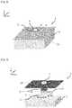
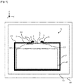
Fig. 2 ] Lafigure 2 est une vue en perspective représentant un mode de réalisation d'un boîtier pour une batterie. - [
Fig. 3 ] Lafigure 3 est une vue en perspective éclatée correspondant à lafigure 2 . - [
Fig. 4 ] Lafigure 4 est une vue en coupe représentant un autre mode de réalisation d'un boîtier pour une batterie, le moyen d'étanchéité comprenant des crochets. - [
Fig. 5 ] Lafigure 5 est une vue en coupe représentant une variante de réalisation d'un boîtier pour une batterie, le moyen d'étanchéité comprenant un ressort. - L'invention propose de munir le boîtier d'une batterie d'un opercule configuré pour se détacher lorsqu'une surpression s'exerce sur sa surface située du côté extérieur du boîtier. L'invention permet, en cas d'incendie de la batterie, d'utiliser une force exercée par de l'eau éjectée d'une lance à incendie et dirigée vers l'opercule pour le détacher et introduire un fluide d'extinction à l'intérieur du boîtier.
- Un mode de réalisation d'un boîtier 1 pour une batterie est décrit ci-après en référence aux
figures 1 ,2 et 3 . - Le boîtier 1 est destiné à entourer et/ou à servir d'enveloppe, notamment de protection, pour une batterie 20. Une telle batterie est par exemple une batterie d'alimentation de puissance d'un véhicule à motorisation électrique ou hybride. Une telle batterie est par exemple de type Lithium-ion (Li-ion).
- Par « batterie », on entend une batterie ou un ensemble de modules batterie.
- Par « pack batterie », on entend un ensemble comprenant un boîtier et au moins une batterie disposée à l'intérieur du boîtier.
- Par surface ou paroi « interne » ou « intérieure », on entend une surface ou paroi située, ou faisant face, à l'intérieur du boîtier 1. Par surface ou paroi « externe » ou « extérieure », on entend une surface ou paroi située à l'extérieur du boîtier 1.
- Par « utilisation normale » ou « usage normal » du boîtier 1, on entend une utilisation ou un usage du boîtier 1 en l'absence de feu ou d'incendie, notamment en fonctionnement normal d'une batterie.
- Le boîtier 1 comprend une enveloppe 2, ou carter.
- Le boîtier 1 comprend un dispositif d'obturation 4 destiné à être monté à l'emplacement d'une ouverture 3 ménagée dans l'enveloppe 2, par exemple dans un carter supérieur 11 d'une batterie ou couvercle 11.
- Le carter supérieur 11 est par exemple une plaque métallique, par exemple cataphorésée. L'épaisseur du carter supérieur 11 est par exemple de l'ordre de 0,8 mm.
- De préférence, l'ouverture 3 peut être de forme circulaire. D'autres formes pourront également être prévues pour l'ouverture 3, par exemple oblongue ou rectangulaire.
- Le diamètre de l'ouverture 3 pourra être choisi de sorte à correspondre sensiblement au diamètre du jet d'eau d'une lance à incendie des pompiers.
- Le diamètre de l'ouverture 3 est par exemple de l'ordre de 50 mm.
- Avantageusement, l'enveloppe 2 peut présenter une portion 12 en forme de cheminée à l'emplacement de l'ouverture 3.
- Avantageusement, le dispositif d'obturation 4 et l'ouverture 3 correspondante sont situés à un emplacement de l'enveloppe 2 directement accessible depuis l'extérieur du véhicule. Il en résulte que les pompiers, en cas d'incendie, peuvent remplir le boîtier 1 avec un fluide d'extinction sans avoir à trop s'approcher du véhicule.
- Le dispositif d'obturation 4 comprend un opercule 5.
- L'opercule 5 présente par exemple la forme d'un disque.
- D'autres formes pourront être prévues pour l'opercule 5. La forme et les dimensions de l'opercule 5 sont choisies de sorte à obturer l'ouverture 3.
- De préférence, on choisira pour l'opercule 5 un matériau résistant aux températures élevées résultant d'un feu d'une batterie. Avantageusement, on choisira pour l'opercule 5 un matériau ayant des propriétés isolantes vis-à-vis des perturbations électromagnétiques émises ou subies par les éléments internes au boîtier 1. Il en résulte qu'un tel opercule 5, outre son rôle de moyen d'obturation de l'ouverture et donc de confinement à l'intérieur du boîtier 1, présente également le rôle de blindage électromagnétique en usage normal du boîtier 1.
- L'opercule 5 comprend par exemple un matériau métallique.
- L'opercule 5 est par exemple en acier, par exemple en acier de type DX54, qui n'est pas thermofusible puisqu'il résiste à de très hautes températures, sa température de fusion étant de l'ordre de 1500°C, ou en aluminium.
- Avantageusement, l'opercule 5 est cataphorésé.
- De préférence, le diamètre de l'opercule 5 est supérieur ou égal au diamètre de l'ouverture 3 de l'enveloppe 2.
- Le diamètre de l'opercule 5 est par exemple supérieur ou égal au diamètre du jet d'une lance à incendie des pompiers, qui est de l'ordre de 50 mm en jet baton.
- Le diamètre D de l'opercule 5 est par exemple compris entre 50 mm et 100 mm, par exemple de l'ordre de 80 mm.
- L'épaisseur de l'opercule 5 est par exemple comprise entre 200 micromètre et 10 mm, par exemple de l'ordre de 5 mm.
- Le diamètre D de l'opercule 5 correspond aux dimensions de l'opercule 5 dans le plan (x,y), et l'épaisseur de l'opercule 5 correspond à sa dimension selon la direction z. Le repère (x, y, z) est un repère orthonormé. Le plan (x, y) correspond à la surface principale du carter supérieur 11.
- En usage normal du boîtier 1, l'opercule 5 permet d'obturer par l'intérieur l'ouverture 3 de l'enveloppe 2. En cas d'incendie, l'opercule 5 correspond à la portion du dispositif d'obturation 4 destinée à se détacher, de façon contrôlée et à un instant bien choisi, sous l'effet d'une surpression exercée sur sa surface externe située du côté extérieur du boîtier, par exemple par le jet d'une lance à incendie.
- En usage normal du boîtier 1, l'opercule 5 est fixé sur une portion de la surface interne de l'enveloppe 2.
- Les bords de l'opercule 5 peuvent également être entourés par une portion de l'enveloppe 2 dans le cas où une cheminée 12 est présente à l'emplacement de l'ouverture 3.
- L'opercule 5 est par exemple fixé sur l'enveloppe 2 par collage par un adhésif 6.
- L'adhésif 6 présente des dimensions adaptées à celles de l'opercule 5.
- L'adhésif 6 présente par exemple la forme d'un anneau, de diamètre interne par exemple sensiblement égal à celui de l'ouverture 3, et de diamètre externe par exemple sensiblement égal à celui de l'opercule 5.
- D'autres formes et dimensions pourront être prévues pour l'adhésif 6, par exemple une forme de disque comme illustré en
figure 3 . - L'adhésif 6 est par exemple de type Tesa 7072.
- L'adhésif 6 est destiné à résister à toutes les phases de vie classiques de la batterie (chocs thermiques, vibrations, étanchéité...). Ceci permet de garantir, en usage normal du boîtier 1, le maintien de la fixation de l'opercule 5 de façon étanche sur l'enveloppe 2, afin d'obturer l'ouverture 3.
- En cas d'incendie du véhicule se propageant à la batterie, ou dans le cas très improbable d'un emballement thermique interne de la batterie, l'adhésif 6 est configuré pour perdre ses propriétés de tenue mécanique avec l'augmentation de température interne. Les dimensions de l'adhésif 6 sont en outre choisies pour permettre un détachement de l'opercule 5 lorsqu'une surpression s'exerce sur sa surface externe située du côté extérieur du boîtier.
- Les dimensions de l'adhésif 6 sont par exemple choisies pour permettre un détachement de l'opercule 5 lorsqu'une force de l'ordre de 130 N s'exerce sur sa surface externe située du côté extérieur du boîtier, et après une exposition à une température d'environ 200 °C pendant 15 min. Une telle force correspond à la force minimale exercée par le jet d'une lance à incendie habituellement utilisée par les pompiers.
- En cas d'incendie, l'opercule 5 est destiné à se détacher, de façon contrôlée et à un instant bien choisi, sous l'effet d'une force exercée par un fluide d'extinction, notamment de l'eau, éjecté d'une lance à incendie, ce qui permet de dégager l'ouverture 3 de l'enveloppe 2 et d'introduire le fluide d'extinction à l'intérieur du boîtier 1.
- Le (ou les) matériau(x) et les dimensions de l'opercule 5 et de l'adhésif 6 seront notamment choisis de sorte que l'opercule 5 puisse se détacher dans le cas d'une force exercée sur la surface externe de l'opercule 5 par le jet d'eau d'une lance à incendie de pompiers, correspondant par exemple à une pression de l'ordre de 6 bars au niveau du camion des pompiers.
- Selon un exemple de réalisation, l'opercule 5 peut être en acier, et présenter un diamètre de l'ordre de 80 mm et une épaisseur de l'ordre de 0,8 mm, et être calibré pour se détacher sous une force exercée sur sa surface externe de l'ordre de 130 N.
- Le dispositif d'obturation 4 comprend en outre un moyen d'étanchéité 7 disposé à l'intérieur du boîtier 1 sous l'opercule 5 et fixé à l'enveloppe 2.
- Le moyen d'étanchéité 7 est destiné à assurer une fermeture de l'ouverture 3 de l'enveloppe 2 du boîtier 1 de façon hermétique ou étanche.
- Le moyen d'étanchéité 7 permet par exemple d'assurer une fermeture de l'ouverture 3 de l'enveloppe 2 du boîtier 1 de façon étanche en cas de dégradation de l'adhésif 6 de fixation de l'opercule 5 sur l'enveloppe 2.
- Le moyen d'étanchéité 7 permet par exemple d'assurer l'étanchéité du boîtier 1 en cas de dégradation trop rapide de l'adhésif 6, ou dans le cas où on souhaite maintenir l'étanchéité du boîtier 1 pour une durée supérieure à 15 min après une exposition à une température interne élevée entraînant la perte des propriétés de tenue mécanique de l'adhésif 6.
- Selon un premier exemple de réalisation, le moyen d'étanchéité 7 peut comprendre une feuille 8 ou plaque.
- La feuille 8 comprend par exemple du Mica, par exemple du Mica composite, qui n'est pas thermofusible puisqu'il résiste à des températures très élevées de l'ordre de 1000°C sans perdre ses propriétés mécaniques. La feuille 8 est disposée à l'intérieur du boîtier 1 sous l'opercule 5 et fixée à l'enveloppe 2.
La feuille 8 peut être fixée par collage par un autre adhésif 9 sur l'enveloppe 2, notamment sur la face intérieure de l'enveloppe 2 où est ménagée l'ouverture 3. - La feuille 8, fixée par l'adhésif 9 à l'enveloppe 2 et disposée sous l'opercule 5, est destinée à limiter la chaleur au niveau de l'adhésif 6 de fixation de l'opercule 5 en cas d'incendie à l'intérieur du boîtier 1. La feuille 8 joue le rôle d'écran thermique. La feuille 8 est configurée pour résister à de très fortes températures et même au feu. En cas d'incendie, la feuille 8 devient cassante mais ne brule pas, assurant ainsi la fonction d'écran thermique.
- La feuille 8 présente par exemple une forme rectangulaire ou carrée. D'autres formes peuvent être prévues pour la feuille 8.
- Avantageusement, la longueur L et la largeur W de la feuille 8 sont supérieures au diamètre D de l'opercule 5. Par longueur L, on entend la dimension de la feuille 8 dans la direction longitudinale x, et par largeur W, on entend la dimension de la feuille 8 dans la direction transversale y. La feuille 8 peut ainsi être fixée sur la surface interne de l'enveloppe 2 autour de l'opercule 5.
- La longueur L de la feuille 8 est par exemple comprise entre 10 mm et 200 mm, par exemple de l'ordre de 130 mm. La largeur W de la feuille 8 est par exemple comprise entre 10 mm et 200 mm, par exemple de l'ordre de 130 mm.
- L'adhésif 9 est par exemple en silicone ou de type Tesa 4965. On choisira pour l'adhésif 9 un matériau résistant à de très fortes températures et même au feu.
- Avantageusement, un embouti dans l'enveloppe 2, par exemple en forme de cheminée 12, autour de l'ouverture 3 permet de maintenir une couche d'air 10 entre la feuille 8 et l'opercule 5. Ceci permet de retarder la propagation de la chaleur en cas de température interne élevée du boîtier 1.
- L'épaisseur de la couche d'air 10 est par exemple de l'ordre de 4 mm.
- Selon un deuxième exemple de réalisation, le moyen d'étanchéité 7 peut comprendre au moins un crochet 14 comme illustré sur la
figure 4 . Des éléments similaires à ceux desfigures 1 à 3 sont désignés par les mêmes références sur lafigure 4 et ne sont pas décrits à nouveau ci-après. - Avantageusement, le moyen d'étanchéité 7 peut être positionné en un point ou en deux points sous l'opercule 5 fixé par l'adhésif 6 à l'enveloppe 2.
- Le moyen d'étanchéité 7 comprend par exemple deux crochets 14. Les crochets 14 sont par exemple disposés sous l'opercule 5 de part et d'autre de l'opercule 5, par exemple de façon diamétralement opposée, par exemple selon la direction longitudinale x. D'autres positionnements d'un ou plusieurs crochets pourront bien entendu être prévus.
- En usage normal du boîtier 1, l'opercule 5 est maintenu par l'adhésif 6 et aucune contrainte n'est appliquée à ce (ou ces) crochets 14 par l'opercule 5.
- En cas d'incendie, si l'adhésif 6 se dégrade trop et ne maintient plus suffisamment l'opercule 5, l'opercule 5 est alors maintenu par l'au moins un crochet 14. L'étanchéité du boîtier 1 reste ainsi assurée.
- Afin de garantir la possibilité de dégagement de l'ouverture 3 par le jet d'une lance à incendie, l'au moins un crochet 14 est configuré pour s'ouvrir sous une force de 130 N, correspondant à la force minimale fournie par le jet d'une lance à incendie habituellement utilisée par les pompiers. Ceci permet de libérer l'opercule 5 et donc de dégager l'ouverture 3.
- Selon un troisième exemple de réalisation, le moyen d'étanchéité 7 peut comprendre un ressort 16 comme illustré sur la
figure 5 . Des éléments similaires à ceux desfigures 1 à 3 sont désignés par les mêmes références sur lafigure 5 et ne sont pas décrits à nouveau ci-après. - Le ressort 16 peut être positionné sous l'opercule 5 fixé par l'adhésif 6 à l'enveloppe 2.
- Une portion du ressort 16 est par exemple fixée sur la face intérieure de l'enveloppe 2 où est ménagée l'ouverture 3. Une autre portion du ressort 16 est par exemple en appui sur l'opercule 5.
- Le ressort 16 est par exemple une lamelle ressort élastique.
- La lamelle 16 peut comprendre une partie plate 17 et une zone de fragilisation 18. La zone de fragilisation 18 est destinée à rompre ou à se déformer plastiquement lorsqu'une force est exercée sur l'opercule 5.
- A la place d'un ressort 16, le moyen d'étanchéité 7 pourra comprendre un autre moyen de rappel élastique. Un ou plusieurs moyens de rappel élastique pourront être prévus.
- En usage normal du boîtier 1, l'opercule 5 est maintenu par l'adhésif 6.
- En cas d'incendie, si l'adhésif 6 se dégrade trop et ne maintient plus suffisamment l'opercule 5, l'opercule de rupture 5 est alors maintenu par le ressort 16. L'étanchéité du boîtier 1 reste ainsi assurée.
- Afin de garantir la possibilité de dégagement de l'ouverture 3 par le jet d'une lance à incendie, le ressort 16 est configuré pour libérer l'opercule 5 sous une force de 130 N, correspondant à la force minimale fournie par le jet d'une lance à incendie habituellement utilisée par les pompiers. L'opercule 5 est extrait de l'ouverture 3 grâce à la force de rappel élastique fournie par le ressort 16, en réaction à la force exercée par le jet d'une lance à incendie. La zone de fragilisation 18 de la lamelle 16 rompt ou se déforme plastiquement sous l'effet de la force exercée sur l'opercule 5, ce qui permet de libérer l'opercule 5.
- Selon un autre exemple de réalisation d'un boîtier, le moyen d'étanchéité 7 peut comprendre au moins crochet 14 et un ressort 16. Autrement dit, les exemples de réalisation des
figures 4 et5 peuvent être combinés. - Un avantage d'un boîtier du type de celui décrit en relation avec les
figures 1 à 5 est lié au fait que le dispositif d'obturation 4 forme, en utilisation normale du boîtier 1, un blindage électromagnétique efficace, simple à mettre en œuvre et présentant un coût réduit. Le dispositif d'obturation 4 permet de rendre possible l'accès à l'intérieur du boîtier 1 en cas d'incendie tout en jouant un rôle d'isolation contre les perturbations électromagnétiques émises ou subies par les éléments internes au boîtier 1 en usage normal. - L'invention concerne également un pack batterie 30 comprenant un boîtier 1 du type de celui décrit en relation avec les
figures 1 à 5 . Le pack batterie 30 comprend par exemple en outre au moins une batterie, notamment d'alimentation de puissance d'un véhicule automobile électrique ou hybride. - L'invention concerne en outre un véhicule automobile 40, notamment à motorisation électrique ou hybride, comprenant un boîtier 1 du type de celui décrit en relation avec les
figures 1 à 5 ou un pack batterie 30 du type de celui décrit ci-dessus. - Un autre avantage d'un boîtier du type de celui décrit en relation avec les
figures 1 à 5 réside dans le fait qu'il permet, en cas d'incendie d'une batterie, d'empêcher l'entrée de fumées et du feu dans l'habitacle du véhicule en résistant aux températures élevées des fumées et du feu. Il en résulte une sécurité accrue des passagers. - Un boîtier du type de celui décrit en relation avec les
figures 1 à 5 permet par exemple d'empêcher l'entrée de fumées et du feu dans l'habitacle pendant au moins 5 minutes après une détection d'emballement thermique d'une batterie. Ceci permet aux passagers de sortir ou d'être extraits du véhicule avant l'entrée de fumées et du feu dans l'habitacle. - Un autre avantage d'un boîtier du type de celui décrit en relation avec les
figures 1 à 5 réside dans le fait qu'il permet de fournir un dispositif efficace d'introduction d'un fluide d'extinction dans un boîtier d'une batterie, utile aux pompiers en cas de feu, tout en améliorant l'efficacité du blindage électromagnétique en usage normal, par rapport aux dispositifs d'extinction de feu d'une batterie connus de l'art antérieur. - Un autre avantage d'un boîtier du type de celui décrit en relation avec les
figures 1 à 5 réside dans son coût réduit. - Un mode d'exécution d'un procédé d'introduction d'un fluide d'extinction dans un boîtier pour une batterie du type de celui décrit en relation avec les
figures 1 à 5 est décrit ci-après. Un tel procédé peut par exemple être utilisé par des pompiers pour éteindre un incendie d'une batterie. - L'invention propose un procédé permettant, en cas d'incendie d'une batterie, d'utiliser la force exercée par le jet d'une lance à incendie pour entraîner le détachement de l'opercule 5 du dispositif d'obturation 4 et ainsi dégager l'ouverture 3 de l'enveloppe 2 du boîtier 1. Il en résulte le dégagement d'un accès direct à l'intérieur du boîtier 1 pour que les pompiers puissent remplir le boîtier 1 d'un fluide d'extinction, notamment de l'eau, et « noyer » la batterie 20 pour éteindre le feu.
- Le procédé comprend une étape d'application d'une surpression sur le dispositif d'obturation 4 de sorte à entraîner le détachement de l'opercule 5.
- La surpression est par exemple obtenue par une force exercée par de l'eau éjectée d'une lance à incendie et dirigée vers le dispositif d'obturation 4.
- L'opercule 5 se détache lorsque la force exercée par le fluide d'extinction présente une valeur seuil ou minimale prédéterminée. La valeur seuil ou minimale prédéterminée de la force exercée peut être choisie selon l'application, les moyens de détachement à disposition et la contrepression interne à laquelle le dispositif doit résister. Selon un exemple de réalisation, la valeur seuil ou minimale prédéterminée de la force exercée peut être de l'ordre de 130 N.
- L'opercule 5 qui s'est détaché permet de dégager l'ouverture 3, ce qui permet l'introduction du fluide d'extinction dans le boîtier 1.
- Un avantage d'un procédé d'introduction d'un fluide d'extinction dans un boîtier pour une batterie du type de celui décrit ci-dessus réside dans le fait que les pompiers peuvent éteindre un incendie d'une batterie tout en restant à une certaine distance du véhicule ou du boîtier. Il en résulte que l'intervention des pompiers est moins risquée.
- Un autre avantage d'un procédé d'introduction d'un fluide d'extinction du type de celui décrit ci-dessus réside dans le fait qu'il permet d'utiliser la force exercée par un jet d'eau d'une lance à incendie dans son état le plus couramment utilisé, par exemple correspondant à une pression de l'ordre de 6 bars au niveau du camion des pompiers. Un jet d'eau d'une lance à incendie présentant une telle pression est couramment utilisé par tous les pompiers du monde. Il en résulte qu'un tel procédé ne requiert aucun aménagement particulier des équipements des pompiers.
- Un autre avantage d'un procédé d'introduction d'un fluide d'extinction du type de celui décrit ci-dessus réside dans le fait que le dégagement de l'ouverture 3 de l'enveloppe 2 du boîtier 1 est réalisé de façon contrôlée. Un tel contrôle de l'instant de dégagement de l'ouverture permet d'éviter l'entrée dans l'habitacle de fumées et/ou du feu confinés dans la batterie, avant que d'éventuels passagers aient pu sortir du véhicule.
- Il a été décrit en relation avec les
figures 1 à 5 un boîtier 1 comprenant un dispositif d'obturation 4. Bien entendu, plusieurs dispositifs d'obturation 4, et plusieurs ouvertures 3 associées, pourront être prévus pour un même boîtier 1. Ceci permettrait d'optimiser pour les pompiers l'accès rapide et simple à au moins un dispositif d'obturation 4, par exemple en cas d'accident de la route. - En variante, un boîtier 1 pour une batterie du type de celui décrit ci-dessus pourrait en outre comprendre d'autres dispositifs, dits dispositifs de « Fireman Access », permettant de donner accès à l'intérieur du boîtier 1 pour l'introduction d'un fluide d'extinction par les pompiers, par exemple les dispositifs « Fireman access » désignent des dispositifs comprenant une zone sécable ou thermo-fusible, notamment disposés du côté de l'interface avec le châssis du véhicule.
- Il a été décrit en relation avec les
figures 1 à 5 un boîtier 1 notamment destiné à entourer une batterie d'alimentation de puissance d'un véhicule automobile, notamment une batterie de type Lithium-ion (Li-ion). Un tel boîtier 1 pourra être utilisé pour toutes applications comportant une batterie à électrolyte inflammable, susceptible d'être soumise à un risque incendie, notamment dans les domaines de l'automobile, du stockage d'énergie stationnaire et de l'aviation, afin de faciliter l'intervention des services de secours. - Un procédé d'introduction d'un fluide d'extinction dans un boîtier 1 pour une batterie a été décrit ci-dessus dans le cas de l'utilisation d'eau comme fluide d'extinction. Bien entendu, d'autres fluides d'extinction que l'eau pourront être utilisés.
Claims (10)
- Boîtier (1) pour une batterie, comprenant une enveloppe (2) et au moins un dispositif d'obturation (4) muni d'un opercule (5) fixé sur l'enveloppe à l'emplacement d'une ouverture (3) ménagée dans l'enveloppe, l'opercule (5) étant collé sur l'enveloppe par un adhésif (6), l'adhésif étant configuré pour perdre ses propriétés de tenue mécanique avec l'augmentation de température interne et pour permettre le détachement de l'opercule lorsqu'une force s'exerce sur sa surface externe située du côté extérieur du boîtier,
le dispositif d'obturation (4) comprenant en outre un moyen d'étanchéité (7) disposé à l'intérieur du boîtier (1) sous l'opercule (5). - Boîtier selon la revendication 1, dans lequel le moyen d'étanchéité (7) comprend une feuille (8) comprenant du Mica.
- Boîtier selon la revendication 2, dans lequel la feuille (8) est collée par un autre adhésif (9) sur la face intérieure de l'enveloppe (2) où est ménagée l'ouverture (3).
- Boîtier selon la revendication 2 ou 3, dans lequel une couche d'air (10) est maintenue entre la feuille (8) et l'opercule (5), l'épaisseur de la couche d'air (10) étant par exemple de l'ordre de 4 mm.
- Boîtier selon la revendication 1, dans lequel le moyen d'étanchéité (7) comprend au moins un crochet (14) et/ou au moins un moyen de rappel élastique, par exemple un ressort (16).
- Boîtier selon la revendication 5, dans lequel l'au moins un crochet (14) et/ou l'au moins un moyen de rappel élastique (16) est configuré pour libérer l'opercule (5) lorsqu'une force supérieure à un seuil prédéfini, notamment 130 N, s'exerce sur la surface externe du dispositif d'obturation (4) située du côté extérieur du boîtier.
- Pack batterie (30), notamment d'alimentation de puissance d'un véhicule automobile électrique ou hybride, comprenant un boîtier (1) selon l'une quelconque des revendications précédentes.
- Véhicule automobile (40), notamment à motorisation électrique ou hybride, comprenant un pack batterie (30) d'alimentation de puissance selon la revendication précédente ou un boîtier (1) selon l'une quelconque des revendications 1 à 6.
- Procédé d'introduction d'un fluide d'extinction dans un boîtier (1) selon l'une quelconque des revendications 1 à 6, comprenant une étape d'application d'une surpression sur le dispositif d'obturation (4) de sorte à entraîner le détachement de l'opercule (5).
- Procédé d'introduction d'un fluide d'extinction dans un boîtier (1) selon la revendication précédente, dans lequel la surpression est obtenue par une force exercée par de l'eau éjectée d'une lance à incendie et dirigée vers le dispositif d'obturation (4).
Applications Claiming Priority (1)
| Application Number | Priority Date | Filing Date | Title |
|---|---|---|---|
| FR1915246A FR3105598A1 (fr) | 2019-12-20 | 2019-12-20 | Boîtier pour une batterie et procédé d’introduction d’un fluide d’extinction dans un tel boîtier. |
Publications (2)
| Publication Number | Publication Date |
|---|---|
| EP3838655A1 true EP3838655A1 (fr) | 2021-06-23 |
| EP3838655B1 EP3838655B1 (fr) | 2025-11-26 |
Family
ID=70738641
Family Applications (1)
| Application Number | Title | Priority Date | Filing Date |
|---|---|---|---|
| EP20214265.9A Active EP3838655B1 (fr) | 2019-12-20 | 2020-12-15 | Boîtier pour une batterie et procédé d'introduction d'un fluide d'extinction dans un tel boîtier |
Country Status (2)
| Country | Link |
|---|---|
| EP (1) | EP3838655B1 (fr) |
| FR (1) | FR3105598A1 (fr) |
Cited By (4)
| Publication number | Priority date | Publication date | Assignee | Title |
|---|---|---|---|---|
| CN114949676A (zh) * | 2022-05-24 | 2022-08-30 | 深圳市博结成科技有限公司 | 一种具有内置灭火装置的散热防潮型电源箱 |
| WO2024126513A1 (fr) * | 2022-12-16 | 2024-06-20 | Ampere S.A.S. | Dispositif de sécurité pour une batterie d'un véhicule électrique ou hybride |
| FR3157004A1 (fr) * | 2023-12-19 | 2025-06-20 | Ampere S.A.S. | Valve de noyage pour batterie d’accumulateurs |
| EP4618239A1 (fr) * | 2024-03-14 | 2025-09-17 | Samsung Sdi Co., Ltd. | Module de stockage d'énergie |
Families Citing this family (1)
| Publication number | Priority date | Publication date | Assignee | Title |
|---|---|---|---|---|
| FR3167310A1 (fr) | 2024-10-16 | 2026-04-17 | Stellantis Auto Sas | Batterie de traction de vehicule automobile avec marquages d’entree d’eau de refroidissement |
Citations (2)
| Publication number | Priority date | Publication date | Assignee | Title |
|---|---|---|---|---|
| US20150056481A1 (en) * | 2012-03-02 | 2015-02-26 | Renault S.A.S. | Filling device for firefighters of a drive battery of an electric or hybrid vehicle |
| EP2861441A1 (fr) * | 2012-06-18 | 2015-04-22 | Peugeot Citroën Automobiles SA | Véhicule automobile comportant un système d'accès rapide a la batterie en cas d'incendie |
-
2019
- 2019-12-20 FR FR1915246A patent/FR3105598A1/fr active Pending
-
2020
- 2020-12-15 EP EP20214265.9A patent/EP3838655B1/fr active Active
Patent Citations (2)
| Publication number | Priority date | Publication date | Assignee | Title |
|---|---|---|---|---|
| US20150056481A1 (en) * | 2012-03-02 | 2015-02-26 | Renault S.A.S. | Filling device for firefighters of a drive battery of an electric or hybrid vehicle |
| EP2861441A1 (fr) * | 2012-06-18 | 2015-04-22 | Peugeot Citroën Automobiles SA | Véhicule automobile comportant un système d'accès rapide a la batterie en cas d'incendie |
Cited By (6)
| Publication number | Priority date | Publication date | Assignee | Title |
|---|---|---|---|---|
| CN114949676A (zh) * | 2022-05-24 | 2022-08-30 | 深圳市博结成科技有限公司 | 一种具有内置灭火装置的散热防潮型电源箱 |
| WO2024126513A1 (fr) * | 2022-12-16 | 2024-06-20 | Ampere S.A.S. | Dispositif de sécurité pour une batterie d'un véhicule électrique ou hybride |
| FR3143534A1 (fr) * | 2022-12-16 | 2024-06-21 | Renault | Dispositif de sécurité pour une batterie d’un véhicule électrique ou hybride |
| FR3157004A1 (fr) * | 2023-12-19 | 2025-06-20 | Ampere S.A.S. | Valve de noyage pour batterie d’accumulateurs |
| WO2025131955A1 (fr) * | 2023-12-19 | 2025-06-26 | Ampere S.A.S. | Valve de noyage pour batterie d'accumulateurs |
| EP4618239A1 (fr) * | 2024-03-14 | 2025-09-17 | Samsung Sdi Co., Ltd. | Module de stockage d'énergie |
Also Published As
| Publication number | Publication date |
|---|---|
| EP3838655B1 (fr) | 2025-11-26 |
| FR3105598A1 (fr) | 2021-06-25 |
Similar Documents
| Publication | Publication Date | Title |
|---|---|---|
| EP3838655B1 (fr) | Boîtier pour une batterie et procédé d'introduction d'un fluide d'extinction dans un tel boîtier | |
| EP3939101A1 (fr) | Boîtier pour une batterie et procédé d'introduction d'un fluide d'extinction dans un tel boîtier | |
| EP2820689B1 (fr) | Dispositif de remplissage par les pompiers d'une batterie de traction d'un vehicule electrique ou hybride | |
| EP1591704B1 (fr) | Vehicule a carburant gazeux et systeme de purge automatique | |
| EP3027510B1 (fr) | Procede et dispositif de liaison et de separation lineaire de deux elements, avec moyens energetiques decales | |
| FR3095895A1 (fr) | Coffre pour batterie | |
| EP2861441B1 (fr) | Véhicule automobile comportant un système d'accès rapide a la batterie en cas d'incendie | |
| WO2022043621A1 (fr) | Systeme de respiration d'une batterie | |
| EP2962340B1 (fr) | Dispositif de sécurité pour une batterie de générateurs électrochimiques au lithium | |
| EP1960238B1 (fr) | Dispositif de generation de gaz pour systeme de securite | |
| FR3116239A1 (fr) | Capuchon destructible pour un ecran de protection d’une batterie | |
| EP4427920A1 (fr) | Dispositif d'obturation adhesif refractaire d'une ouverture traversante d'un element de batiment ou de vehicule, procede de fabrication et installation pour la mise en oeuvre de ce procede | |
| EP3163249B1 (fr) | Allumeur pour propulseur | |
| FR3157004A1 (fr) | Valve de noyage pour batterie d’accumulateurs | |
| EP4263002B1 (fr) | Bouchon thermofusible | |
| FR3116240A1 (fr) | Systeme de batterie comprenant un ecran de protection | |
| WO2024132481A1 (fr) | Module d'accumulateurs apte à la gestion d'une surpression interne | |
| EP4654361A1 (fr) | Dispositif de ventilation avec ecran protecteur pour boîtier de batterie(s), et procede d assemblage | |
| WO2022090204A1 (fr) | Dispositif de sécurité adaptable sur une cellule électrochimique | |
| EP4353329A1 (fr) | Extincteur d'incendie de moteur | |
| FR3143534A1 (fr) | Dispositif de sécurité pour une batterie d’un véhicule électrique ou hybride | |
| WO2017072459A1 (fr) | Porte d'acces au reservoir de carburant ou a une zone seche d'un aeronef | |
| FR2922874A1 (fr) | Procede et dispositif pyrotechnique autonome de pressurisation et eventuellement ouverture d'enceintes. |
Legal Events
| Date | Code | Title | Description |
|---|---|---|---|
| PUAI | Public reference made under article 153(3) epc to a published international application that has entered the european phase |
Free format text: ORIGINAL CODE: 0009012 |
|
| STAA | Information on the status of an ep patent application or granted ep patent |
Free format text: STATUS: THE APPLICATION HAS BEEN PUBLISHED |
|
| AK | Designated contracting states |
Kind code of ref document: A1 Designated state(s): AL AT BE BG CH CY CZ DE DK EE ES FI FR GB GR HR HU IE IS IT LI LT LU LV MC MK MT NL NO PL PT RO RS SE SI SK SM TR |
|
| STAA | Information on the status of an ep patent application or granted ep patent |
Free format text: STATUS: REQUEST FOR EXAMINATION WAS MADE |
|
| 17P | Request for examination filed |
Effective date: 20211223 |
|
| RBV | Designated contracting states (corrected) |
Designated state(s): AL AT BE BG CH CY CZ DE DK EE ES FI FR GB GR HR HU IE IS IT LI LT LU LV MC MK MT NL NO PL PT RO RS SE SI SK SM TR |
|
| RAP3 | Party data changed (applicant data changed or rights of an application transferred) |
Owner name: RENAULT S.A.S |
|
| RAP3 | Party data changed (applicant data changed or rights of an application transferred) |
Owner name: RENAULT S.A.S |
|
| P01 | Opt-out of the competence of the unified patent court (upc) registered |
Effective date: 20230608 |
|
| STAA | Information on the status of an ep patent application or granted ep patent |
Free format text: STATUS: EXAMINATION IS IN PROGRESS |
|
| 17Q | First examination report despatched |
Effective date: 20240115 |
|
| RAP1 | Party data changed (applicant data changed or rights of an application transferred) |
Owner name: AMPERE SAS |
|
| GRAP | Despatch of communication of intention to grant a patent |
Free format text: ORIGINAL CODE: EPIDOSNIGR1 |
|
| STAA | Information on the status of an ep patent application or granted ep patent |
Free format text: STATUS: GRANT OF PATENT IS INTENDED |
|
| RIC1 | Information provided on ipc code assigned before grant |
Ipc: B60L 50/64 20190101AFI20250613BHEP Ipc: H01M 10/42 20060101ALI20250613BHEP Ipc: H01M 50/157 20210101ALI20250613BHEP Ipc: H01M 50/171 20210101ALI20250613BHEP Ipc: H01M 50/197 20210101ALI20250613BHEP Ipc: H01M 50/249 20210101ALI20250613BHEP Ipc: B60L 3/00 20190101ALI20250613BHEP |
|
| INTG | Intention to grant announced |
Effective date: 20250630 |
|
| RIN1 | Information on inventor provided before grant (corrected) |
Inventor name: RAT, NATALIE Inventor name: D'HERLINCOURT, PAULINE Inventor name: MICHEL, PHILIPPE Inventor name: ORIGUCHI, MASATO |
|
| GRAS | Grant fee paid |
Free format text: ORIGINAL CODE: EPIDOSNIGR3 |
|
| GRAA | (expected) grant |
Free format text: ORIGINAL CODE: 0009210 |
|
| STAA | Information on the status of an ep patent application or granted ep patent |
Free format text: STATUS: THE PATENT HAS BEEN GRANTED |
|
| AK | Designated contracting states |
Kind code of ref document: B1 Designated state(s): AL AT BE BG CH CY CZ DE DK EE ES FI FR GB GR HR HU IE IS IT LI LT LU LV MC MK MT NL NO PL PT RO RS SE SI SK SM TR |
|
| REG | Reference to a national code |
Ref country code: CH Ref legal event code: F10 Free format text: ST27 STATUS EVENT CODE: U-0-0-F10-F00 (AS PROVIDED BY THE NATIONAL OFFICE) Effective date: 20251126 Ref country code: GB Ref legal event code: FG4D Free format text: NOT ENGLISH |
|
| REG | Reference to a national code |
Ref country code: IE Ref legal event code: FG4D Free format text: LANGUAGE OF EP DOCUMENT: FRENCH |
|
| REG | Reference to a national code |
Ref country code: DE Ref legal event code: R096 Ref document number: 602020062703 Country of ref document: DE |
|
| REG | Reference to a national code |
Ref country code: NL Ref legal event code: MP Effective date: 20251126 |
|
| PGFP | Annual fee paid to national office [announced via postgrant information from national office to epo] |
Ref country code: GB Payment date: 20260123 Year of fee payment: 6 |
|
| PG25 | Lapsed in a contracting state [announced via postgrant information from national office to epo] |
Ref country code: ES Free format text: LAPSE BECAUSE OF FAILURE TO SUBMIT A TRANSLATION OF THE DESCRIPTION OR TO PAY THE FEE WITHIN THE PRESCRIBED TIME-LIMIT Effective date: 20251126 |
|
| REG | Reference to a national code |
Ref country code: LT Ref legal event code: MG9D |
|
| PG25 | Lapsed in a contracting state [announced via postgrant information from national office to epo] |
Ref country code: NO Free format text: LAPSE BECAUSE OF FAILURE TO SUBMIT A TRANSLATION OF THE DESCRIPTION OR TO PAY THE FEE WITHIN THE PRESCRIBED TIME-LIMIT Effective date: 20260226 |
|
| PGFP | Annual fee paid to national office [announced via postgrant information from national office to epo] |
Ref country code: DE Payment date: 20260121 Year of fee payment: 6 |
|
| PG25 | Lapsed in a contracting state [announced via postgrant information from national office to epo] |
Ref country code: HR Free format text: LAPSE BECAUSE OF FAILURE TO SUBMIT A TRANSLATION OF THE DESCRIPTION OR TO PAY THE FEE WITHIN THE PRESCRIBED TIME-LIMIT Effective date: 20251126 Ref country code: AT Free format text: LAPSE BECAUSE OF FAILURE TO SUBMIT A TRANSLATION OF THE DESCRIPTION OR TO PAY THE FEE WITHIN THE PRESCRIBED TIME-LIMIT Effective date: 20251126 Ref country code: FI Free format text: LAPSE BECAUSE OF FAILURE TO SUBMIT A TRANSLATION OF THE DESCRIPTION OR TO PAY THE FEE WITHIN THE PRESCRIBED TIME-LIMIT Effective date: 20251126 |
|
| REG | Reference to a national code |
Ref country code: AT Ref legal event code: MK05 Ref document number: 1860768 Country of ref document: AT Kind code of ref document: T Effective date: 20251126 |
|
| PG25 | Lapsed in a contracting state [announced via postgrant information from national office to epo] |
Ref country code: NL Free format text: LAPSE BECAUSE OF FAILURE TO SUBMIT A TRANSLATION OF THE DESCRIPTION OR TO PAY THE FEE WITHIN THE PRESCRIBED TIME-LIMIT Effective date: 20251126 |
|
| PG25 | Lapsed in a contracting state [announced via postgrant information from national office to epo] |
Ref country code: RS Free format text: LAPSE BECAUSE OF FAILURE TO SUBMIT A TRANSLATION OF THE DESCRIPTION OR TO PAY THE FEE WITHIN THE PRESCRIBED TIME-LIMIT Effective date: 20260226 |
|
| PG25 | Lapsed in a contracting state [announced via postgrant information from national office to epo] |
Ref country code: IS Free format text: LAPSE BECAUSE OF FAILURE TO SUBMIT A TRANSLATION OF THE DESCRIPTION OR TO PAY THE FEE WITHIN THE PRESCRIBED TIME-LIMIT Effective date: 20260326 |
|
| PGFP | Annual fee paid to national office [announced via postgrant information from national office to epo] |
Ref country code: FR Payment date: 20260123 Year of fee payment: 6 |
|
| PG25 | Lapsed in a contracting state [announced via postgrant information from national office to epo] |
Ref country code: PT Free format text: LAPSE BECAUSE OF FAILURE TO SUBMIT A TRANSLATION OF THE DESCRIPTION OR TO PAY THE FEE WITHIN THE PRESCRIBED TIME-LIMIT Effective date: 20260326 |
|
| PG25 | Lapsed in a contracting state [announced via postgrant information from national office to epo] |
Ref country code: PL Free format text: LAPSE BECAUSE OF FAILURE TO SUBMIT A TRANSLATION OF THE DESCRIPTION OR TO PAY THE FEE WITHIN THE PRESCRIBED TIME-LIMIT Effective date: 20251126 |
|
| PG25 | Lapsed in a contracting state [announced via postgrant information from national office to epo] |
Ref country code: LV Free format text: LAPSE BECAUSE OF FAILURE TO SUBMIT A TRANSLATION OF THE DESCRIPTION OR TO PAY THE FEE WITHIN THE PRESCRIBED TIME-LIMIT Effective date: 20251126 |