EP3838671A1 - Système de circuit - Google Patents
Système de circuit Download PDFInfo
- Publication number
- EP3838671A1 EP3838671A1 EP19216444.0A EP19216444A EP3838671A1 EP 3838671 A1 EP3838671 A1 EP 3838671A1 EP 19216444 A EP19216444 A EP 19216444A EP 3838671 A1 EP3838671 A1 EP 3838671A1
- Authority
- EP
- European Patent Office
- Prior art keywords
- current
- animation
- control device
- lamp control
- light module
- Prior art date
- Legal status (The legal status is an assumption and is not a legal conclusion. Google has not performed a legal analysis and makes no representation as to the accuracy of the status listed.)
- Withdrawn
Links
Images


Classifications
-
- B—PERFORMING OPERATIONS; TRANSPORTING
- B60—VEHICLES IN GENERAL
- B60Q—ARRANGEMENT OF SIGNALLING OR LIGHTING DEVICES, THE MOUNTING OR SUPPORTING THEREOF OR CIRCUITS THEREFOR, FOR VEHICLES IN GENERAL
- B60Q11/00—Arrangement of monitoring devices for devices provided for in groups B60Q1/00 - B60Q9/00
- B60Q11/005—Arrangement of monitoring devices for devices provided for in groups B60Q1/00 - B60Q9/00 for lighting devices, e.g. indicating if lamps are burning or not
-
- H—ELECTRICITY
- H05—ELECTRIC TECHNIQUES NOT OTHERWISE PROVIDED FOR
- H05B—ELECTRIC HEATING; ELECTRIC LIGHT SOURCES NOT OTHERWISE PROVIDED FOR; CIRCUIT ARRANGEMENTS FOR ELECTRIC LIGHT SOURCES, IN GENERAL
- H05B45/00—Circuit arrangements for operating light-emitting diodes [LED]
- H05B45/10—Controlling the intensity of the light
- H05B45/14—Controlling the intensity of the light using electrical feedback from LEDs or from LED modules
-
- B—PERFORMING OPERATIONS; TRANSPORTING
- B60—VEHICLES IN GENERAL
- B60Q—ARRANGEMENT OF SIGNALLING OR LIGHTING DEVICES, THE MOUNTING OR SUPPORTING THEREOF OR CIRCUITS THEREFOR, FOR VEHICLES IN GENERAL
- B60Q1/00—Arrangement of optical signalling or lighting devices, the mounting or supporting thereof or circuits therefor
- B60Q1/26—Arrangement of optical signalling or lighting devices, the mounting or supporting thereof or circuits therefor the devices being primarily intended to indicate the vehicle, or parts thereof, or to give signals, to other traffic
- B60Q1/34—Arrangement of optical signalling or lighting devices, the mounting or supporting thereof or circuits therefor the devices being primarily intended to indicate the vehicle, or parts thereof, or to give signals, to other traffic for indicating change of drive direction
- B60Q1/38—Arrangement of optical signalling or lighting devices, the mounting or supporting thereof or circuits therefor the devices being primarily intended to indicate the vehicle, or parts thereof, or to give signals, to other traffic for indicating change of drive direction using immovably-mounted light sources, e.g. fixed flashing lamps
- B60Q1/381—Arrangement of optical signalling or lighting devices, the mounting or supporting thereof or circuits therefor the devices being primarily intended to indicate the vehicle, or parts thereof, or to give signals, to other traffic for indicating change of drive direction using immovably-mounted light sources, e.g. fixed flashing lamps with several light sources activated in sequence, e.g. to create a sweep effect
-
- B—PERFORMING OPERATIONS; TRANSPORTING
- B60—VEHICLES IN GENERAL
- B60Q—ARRANGEMENT OF SIGNALLING OR LIGHTING DEVICES, THE MOUNTING OR SUPPORTING THEREOF OR CIRCUITS THEREFOR, FOR VEHICLES IN GENERAL
- B60Q11/00—Arrangement of monitoring devices for devices provided for in groups B60Q1/00 - B60Q9/00
- B60Q11/005—Arrangement of monitoring devices for devices provided for in groups B60Q1/00 - B60Q9/00 for lighting devices, e.g. indicating if lamps are burning or not
- B60Q11/007—Arrangement of monitoring devices for devices provided for in groups B60Q1/00 - B60Q9/00 for lighting devices, e.g. indicating if lamps are burning or not the lighting devices indicating change of drive direction
-
- H—ELECTRICITY
- H05—ELECTRIC TECHNIQUES NOT OTHERWISE PROVIDED FOR
- H05B—ELECTRIC HEATING; ELECTRIC LIGHT SOURCES NOT OTHERWISE PROVIDED FOR; CIRCUIT ARRANGEMENTS FOR ELECTRIC LIGHT SOURCES, IN GENERAL
- H05B45/00—Circuit arrangements for operating light-emitting diodes [LED]
- H05B45/50—Circuit arrangements for operating light-emitting diodes [LED] responsive to malfunctions or undesirable behaviour of LEDs; responsive to LED life; Protective circuits
- H05B45/58—Circuit arrangements for operating light-emitting diodes [LED] responsive to malfunctions or undesirable behaviour of LEDs; responsive to LED life; Protective circuits involving end of life detection of LEDs
-
- B—PERFORMING OPERATIONS; TRANSPORTING
- B60—VEHICLES IN GENERAL
- B60Q—ARRANGEMENT OF SIGNALLING OR LIGHTING DEVICES, THE MOUNTING OR SUPPORTING THEREOF OR CIRCUITS THEREFOR, FOR VEHICLES IN GENERAL
- B60Q2900/00—Features of lamps not covered by other groups in B60Q
- B60Q2900/40—Several lamps activated in sequence, e.g. sweep effect, progressive activation
Definitions
- incandescent lamps In the past few decades, lighting technology has been dominated by light sources in the form of fluorescent lamps or incandescent lamps. In comparison to fluorescent lamps, incandescent lamps could be made particularly compact, making them particularly preferred for use in optical systems in which a defined, precisely determined light distribution has to be emitted. Such optical systems can be, for example, vehicle headlights via which low beam distributions, high beam distributions, etc. are to be emitted.
- these incandescent lamps are regularly supplied via relays which are embedded in a circuit and which are connected in series with the lamps and which can be activated and deactivated by operating elements that can be switched manually and / or automatically. These components can be part of a lamp control device.
- Incandescent lamps have a limited service life, which is usually well below the service life of the product in which the incandescent lamp is used. The lamps must therefore be replaced regularly.
- a failure of an incandescent lamp is typically caused by a crack in the light wire, which interrupts the flow of current through the incandescent lamp.
- lamp control devices In order to detect the failure of a lamp as quickly as possible, lamp control devices often have means for current detection, in order to monitor the incandescent lamp draw conclusions on its functionality. If the current falls below a predeterminable minimum value in spite of the activated circuit, a lamp failure is deduced and an error routine is triggered.
- incandescent lamps are largely being displaced as light sources in modern lighting devices.
- an incandescent lamp can be replaced by using a freely selectable number of semiconductor light sources, in particular LEDs.
- LEDs semiconductor light sources
- these components have a significantly longer service life, individual components can still fail for various reasons.
- a modern lighting device which now has a large number of individual light sources, typically does not fail in its entirety, but rather only individual light sources fail. It can therefore happen that a modern lighting device, despite defective individual LEDs, continues to draw current due to the remaining functioning LEDs at a level that would be classified as normal operating current by a conventional lamp control device (see e.g.
- the conventional lamp control units do not do justice to this fact, since they basically require a binary operating behavior in order to be able to differentiate between function and failure.
- One object of the invention is therefore to create a circuit system with which modern light modules can be supplied with a number of light sources and at the same time the functionality of the light sources can be monitored.
- the light module has a number of individually electrically supplied light sources, a microcontroller for detecting the operating state of the individual light sources, and at least one controllable aid for manipulating the power consumption of the light module
- Microcontroller is supplied with at least one predeterminable comparison information and the microcontroller is set up to output a control signal by comparing the detected operating state of the individual light sources with the comparison information, the control signal being fed to the controllable aid for its control and the controllable aid depending on the current consumption of the Light module manipulated.
- the microcontroller can be set up not only to detect the operating state of the light sources, but also to control the operating state of the light sources themselves.
- the lamp control device is set up to output an operating voltage and an operating current to the light module and is connected to the light module.
- the microcontroller can be put into a power-saving mode during the period in which no intervention by the device is required.
- the microcontroller can be designed to detect and monitor the operating state of each light source individually.
- the expression “a number of” is understood - unless stated otherwise - to mean a number which can be, for example, two, three, four or more, in particular six, eight, ten, twelve, twenty or more than twenty.
- the person skilled in the art is able to select the number of the respective light sources in accordance with the light distribution and / or light function to be emitted.
- the error routine includes switching off the light module and / or outputting an error signal.
- controllable aid is set up to switch off the supply of the electrical light sources if the detected operating state deviates from a target state derived from the comparison information, so that the current consumed falls below the lamp control device threshold value and the lamp control device draws conclusions about the presence of a fault.
- the aid is set up to switch off the individual light sources in their entirety.
- the aid is set up to connect a current sink.
- the current sink is designed as an electrical consumer in the form of an ohmic resistor, in particular an ohmic resistor connected in parallel to the light sources. In this way, the power consumption of the light module can be increased in a simple manner, e.g. if the power consumption by the light sources is low in the course of a running light effect.
- the comparison information includes a continuous operation threshold value which is above the lamp control device threshold value. It can be provided that the comparison information includes a representation of an animation signal that relates to an animation in the form of a chronological sequence of switching on and / or switching off the individual light sources, in particular to generate a running light effect, from which the chronological sequence of the power consumption of the light sources of the Light module can be derived and the controllable aid comprises a current sink and is controlled by the microcontroller in such a way that the continuous operating threshold value is not undershot during the course of the animation through targeted activation of the current sink even when individual light sources are deactivated due to animation.
- a conventional "binary" lamp control device can continue to be used, even if light effects such as running light effects are implemented by the light module and the power consumption by the light sources fluctuates.
- the current sink can be kept active until the lighting effect is complete.
- the light module is activated by actuating a Direction indicator operating element includes activatable animation control device, which controls the sequence of an animation and for this purpose controls the individual light sources.
- the microcontroller detects the current power consumption of the light module and, if a value is exceeded that consists of the sum of the continuous operating threshold value and the current consumed by the current sink, causes the current sink to be switched off. In this way, unnecessary energy consumption can be prevented and the use of the current sink can be reduced to those situations in which a current consumption threshold value is undershot despite the correct sequence of an animation.
- the microcontroller is set up to detect the number of switch-on and / or switch-off maneuvers of the light sources (see also Fig. 4 and 5 ) and thereby inferring the end of an animation, and / or the animation control device is set up to activate the current sink at the end of the animation and to signal the end of the animation to the microcontroller based on the current jump caused by it, the light module and the upstream lamp control device is designed in such a way that the energy supply of the animation control device is maintained until the end of the animation is determined.
- Terminal control can be implemented in this way.
- the animation control device can be designed as an independent module comprising the light sources, which in turn is assigned to the lamp module.
- the animation control device can also be designed as part of the microcontroller or can be controlled by it.
- the lamp control device is also set up to detect the presence of a current jump in the current of the supplied light module, the lamp control device also being set up to detect the start of an animation and to count the number of current jumps based on the start of the animation, with the lamp control device is supplied with a reference value which represents the number of current jumps contained in a completely completed animation, the lamp control device also being set up to use a comparison of the detected To infer the number of current jumps with the reference value at the end of the animation, and preferably then at least temporarily adjust the power supply to the light module.
- the temporary shutdown can last, for example, until a start signal is received, with which a new sequence of an animation can be started.
- the lamp control device can also be set up to detect the level of current jumps in the current of the supplied light module, the lamp control device being supplied with at least one reference value corresponding to the animation and indicating the level of the expected current jumps, the lamp control device also being set up to determine the level of each Compare the jump in current with the reference value and, if it deviates from the reference value, infer the end of the animation, and then at least temporarily stop the power supply to the light module.
- the animation can start again when a new start signal is received. It can be particularly favorable if the current sink is selected in such a way that the current jump when the current sink is switched on has twice the size of a current jump when a light source is switched on.
- the lamp control device is set up to record the duration of an animation and to maintain the power supply of the light module until a target supply period has elapsed, the target supply period being determined by the low time value selected from the following two time values: ⁇ permissible Maximum duration of an animation, duration until the end of the animation ⁇ , whereby in the case of exceeding a maximum duration of an animation at the same time Failure to reach the end of the animation draws conclusions about a faulty animation sequence and the power supply is stopped. This ensures that if the animation runs correctly, the supply is ensured right up to the end of the animation.
- the animation is faulty - e.g. if there are no current jumps due to a failure of a light source - the existence of an error can be inferred by the expiry of the maximum period and the supply can be stopped.
- the light sources are semiconductor light sources, in particular LED light sources.
- the invention further relates to a lighting or signaling device, in particular a direction indicator, comprising a circuit system according to the invention.
- the invention relates to a vehicle headlight, in particular a motor vehicle headlight, comprising a lighting or signaling device according to the invention.
- the invention further relates to a vehicle, in particular a motor vehicle, comprising a lighting or signaling device according to the invention and / or a vehicle headlight according to the invention.
- FIG. 1 shows a schematic representation of a circuit system 1 according to the invention.
- the circuit system 1 comprises a light module 2 for emitting a light distribution and a lamp control device 3 for the electrical supply and for monitoring the functionality of the light module 2.
- the lamp control device 3 can be a commercially available lamp control device to monitor the functionality of the light module 2, the current I consumed by the light module 2 in the operating state is recorded and compared with a lamp control device threshold value I fail, max (see Fig. 2 ).
- the lamp control device 3 is set up to infer the presence of an error and to trigger an error routine F when the lamp control device threshold value I fail, max is undershot.
- a light module 2 ' is also shown with dashed lines, which represents a conventional light module comprising an incandescent lamp.
- a light module 2 ' can be detected in a simple manner by the lamp control device 3 by comparison with a suitably selected threshold value due to the binary operating behavior of incandescent lamps (high current consumption during normal operation, failure of the current consumption when the lamp fails) become.
- This light module 2 ' is only shown as an example and is not the subject of the invention or of the circuit system 1 according to the invention.
- the light module 2 of the circuit system 1 is - as will be discussed below - set up to behave analogously to a conventional light module 2 'with regard to its power consumption despite the use of several light sources in the event of a fault and thus to be able to be controlled and monitored by the lamp control device 3 .
- the light module 2 has a number of individually electrically supplied light sources 2a, a microcontroller 6 for detecting the operating state of the individual light sources 2a, and at least one controllable aid 4 for manipulating the power consumption of the light module 2.
- At least one specifiable comparison information item is fed to the microcontroller 6, for example in the form of a threshold value I IO, min, or a representation signal S A , the comparison information item being discussed in greater detail below.
- the microcontroller 6 is set up to output a control signal S S by comparing the detected operating state of the individual light sources 2a with the comparison information I IO, min and / or S A , the control signal Ss being fed to the controllable aid 4 for its control and the controllable Aid 4 manipulated the power consumption of the light module 2 as a function thereof.
- the controllable aid 4 is set up to switch off the supply of the electrical light sources 2a if the detected operating state deviates from a target state derived from the comparison information (for example a continuous operating threshold value I IO, min or the signal S A ), so that the current I consumed is below the
- the lamp control device threshold value I fail, max falls and the lamp control device 3 draws conclusions about the presence of a fault.
- the range of values that is above I IO, min is denoted by 7a
- the range between I IO, min and I fail, max is denoted by 7b
- the range that is below I fail, max denoted by the reference numeral 7c.
- the aid 4 is set up to connect a current sink 4a in the form of a parallel resistor.
- the aid 4 can also be set up to be connected to the light sources to activate serially located switches in order to force the shutdown of all light sources.
- the comparison information can include a representation of an animation signal S A.
- the animation relates to a chronological sequence of switching on and / or switching off the individual light sources 2a, for example to generate a running light effect of a direction indicator.
- the time sequence of the power consumption of the light sources 2a of the light module 2 can in turn be derived from this.
- the aid 4 can switch on the current sink 4a so that the total current consumption of the light module 2 is not below the continuous operating threshold value I IO, min, even if individual light sources 2a are deactivated due to animation.
- the light module 2 comprises an animation control device 5, which can be activated by actuating a direction indicator control element, which controls the sequence of an animation and for this purpose controls the individual light sources 2a.
- Figure 2 shows a schematic representation of the operating behavior of a conventional light module that has the binary functional behavior already mentioned.
- Figure 3 shows the operating behavior of a modern light module comprising a plurality of light sources in different scenarios.
- Variant A shows a scenario in which a single light source fails and the power consumption drops, but is still above the continuous operating threshold value I IO, min .
- an error would not be recognized either by the lamp control device or by comparison with the continuous operating threshold value I IO, min , since the current is still above the corresponding limits I IO, min and I fail, max .
- this error can be recognized by the individual detection of the operating state of the light sources 2a by means of the microcontroller 6.
- Scenario B in which the failure of a light source 2a leads to a power loss that is to an operating current I leads below the value of I IO, min. This error is also recognized by the microcontroller 6.
- Scenario C subsequently shows the intervention of the microcontroller 6, by means of which the error is also made recognizable by the lamp control device 3. For this purpose, the controller 6 switches off the remaining light sources 2a and thus forces the current I actual to fall below the limit I fail, max . This undershoot is detected by the lamp control device 3 and a customary error routine F can be triggered.
- Figure 4 shows a scenario in which a running light effect is achieved by successively switching on the light sources 2a.
- the current I is increased according to the sequence of power-stepped on, the current I is initially fail below the threshold value I, is max.
- the lamp control device 3 would thus actually recognize an error, although the light module 2 is functioning properly.
- This can be avoided by adding an additional current I 4 through the light module 2 by connecting a current sink by means of the aid 4 , whereby the current is above the limit I IO, min even when individual light sources 2a are switched off due to animation. If the total current consumption of the light module 2 exceeds twice the value of I 4 , the current sink can also be deactivated again.
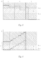
- Figure 5 shows an exemplary representation of the acquisition of an animation.
- the jumps in current are detected, for example by the lamp control device 3, so that conclusions can be drawn about the progress of the animation.
- This detection can be carried out with the signal S A representing the animation or with a signal S A derived therefrom
- Figure 1 shown reference value R 1 are compared and evaluated.
- the crosses X indicate those time ranges in which the current sink X is switched on.
- FIG. 5 shows Figure 5 a variant of the invention in which the lamp control device 3 is also set up to detect the presence of a current jump I s in the current I ist of the supplied light module 2, the lamp control device 3 also being set up to detect the start of an animation and the number of current jumps Counting I s starting from the start of the animation, the lamp control device 3 being supplied with a reference value R 1 which reproduces the number of current jumps I s contained in a fully completed animation, the lamp control device 3 also being set up based on a comparison of the recorded number the current jumps I s with the reference value R 1 to infer the end of the animation, and preferably then at least temporarily adjust the power supply to the light module 2.
- the line below the line containing the "X" symbols shows the number of LED light sources that are switched on at the time. The same notation also applies to Fig. 6 .
- FIG. 6 shows an exemplary representation of an alternative possibility for capturing an animation.
- the lamp control device 3 is also set up therein to detect the level of current jumps I s of the current I ist of the supplied light module 2, the lamp control device 3 being supplied with at least one reference value R 2 corresponding to the animation and indicating the level of the expected current jumps I s
- Lamp control device 3 is also set up to compare the magnitude of each current jump I s with the reference value R 2 and, if it deviates from the reference value R 2, to infer the end of the animation, and then to at least temporarily adjust the power supply to the light module 2.
- the current sink 4a can be selected in such a way that the current jump I 4 when the current sink 4a is switched on has twice the size of a current jump I s when a light source 2a is switched on, so that when a light source 2a is switched on and the current sink 4a is switched off to the lamp control device 3 at the same time negative current jump I s is simulated in the amount of the usual light source current.
- the lamp control device 3 is further set up to record the duration of an animation and to maintain the power supply of the light module 2 until a target supply period has expired, the target supply period being determined by the low time value selected from the following two time values is: ⁇ permissible maximum duration of an animation; Duration until the end of the animation ⁇ , whereby in the event that a maximum duration of an animation is exceeded and the animation end is not reached at the same time, a conclusion is drawn that the animation was running incorrectly and the power supply is set.
Landscapes
- Engineering & Computer Science (AREA)
- Mechanical Engineering (AREA)
- Lighting Device Outwards From Vehicle And Optical Signal (AREA)
- Circuit Arrangement For Electric Light Sources In General (AREA)
Priority Applications (6)
| Application Number | Priority Date | Filing Date | Title |
|---|---|---|---|
| EP19216444.0A EP3838671A1 (fr) | 2019-12-16 | 2019-12-16 | Système de circuit |
| EP20816202.4A EP4077048B1 (fr) | 2019-12-16 | 2020-12-03 | Phare de véhicule comprenant un système de circuit |
| KR1020227020456A KR102759179B1 (ko) | 2019-12-16 | 2020-12-03 | 회로 시스템 |
| JP2022536828A JP7317238B2 (ja) | 2019-12-16 | 2020-12-03 | 回路システム |
| CN202080086973.5A CN114829199B (zh) | 2019-12-16 | 2020-12-03 | 电路系统 |
| PCT/EP2020/084443 WO2021122032A1 (fr) | 2019-12-16 | 2020-12-03 | Système de circuit |
Applications Claiming Priority (1)
| Application Number | Priority Date | Filing Date | Title |
|---|---|---|---|
| EP19216444.0A EP3838671A1 (fr) | 2019-12-16 | 2019-12-16 | Système de circuit |
Publications (1)
| Publication Number | Publication Date |
|---|---|
| EP3838671A1 true EP3838671A1 (fr) | 2021-06-23 |
Family
ID=68917545
Family Applications (2)
| Application Number | Title | Priority Date | Filing Date |
|---|---|---|---|
| EP19216444.0A Withdrawn EP3838671A1 (fr) | 2019-12-16 | 2019-12-16 | Système de circuit |
| EP20816202.4A Active EP4077048B1 (fr) | 2019-12-16 | 2020-12-03 | Phare de véhicule comprenant un système de circuit |
Family Applications After (1)
| Application Number | Title | Priority Date | Filing Date |
|---|---|---|---|
| EP20816202.4A Active EP4077048B1 (fr) | 2019-12-16 | 2020-12-03 | Phare de véhicule comprenant un système de circuit |
Country Status (5)
| Country | Link |
|---|---|
| EP (2) | EP3838671A1 (fr) |
| JP (1) | JP7317238B2 (fr) |
| KR (1) | KR102759179B1 (fr) |
| CN (1) | CN114829199B (fr) |
| WO (1) | WO2021122032A1 (fr) |
Families Citing this family (1)
| Publication number | Priority date | Publication date | Assignee | Title |
|---|---|---|---|---|
| CN113114366A (zh) * | 2021-03-18 | 2021-07-13 | 武汉英飞光创科技有限公司 | 一种实时功耗监测的光模块电路及监测方法 |
Citations (4)
| Publication number | Priority date | Publication date | Assignee | Title |
|---|---|---|---|---|
| US5790017A (en) * | 1996-08-26 | 1998-08-04 | Berryhill; Paul J. | Vehicle turn signal control system and method |
| DE10107578A1 (de) * | 2001-02-17 | 2002-08-29 | Hella Kg Hueck & Co | Lichtanlage für Kraftfahrzeuge |
| US20120074856A1 (en) * | 2009-06-09 | 2012-03-29 | Go Takata | Light-emitting element driving device |
| DE102015201739A1 (de) * | 2014-02-04 | 2015-08-06 | Koito Manufacturing Co., Ltd. | Fahrzeugleuchte |
Family Cites Families (9)
| Publication number | Priority date | Publication date | Assignee | Title |
|---|---|---|---|---|
| US7188984B2 (en) * | 2003-04-17 | 2007-03-13 | Visteon Global Technologies, Inc. | LED headlamp array |
| US7276861B1 (en) * | 2004-09-21 | 2007-10-02 | Exclara, Inc. | System and method for driving LED |
| CN1907755A (zh) * | 2005-08-02 | 2007-02-07 | 唐晓泉 | 具有事故安全功能的机动车后部信号灯控制单元 |
| TWI391029B (zh) * | 2007-12-31 | 2013-03-21 | Ampower Technology Co Ltd | 放電燈驅動系統 |
| DE102010023583A1 (de) * | 2010-06-12 | 2011-12-15 | Automotive Lighting Reutlingen Gmbh | Verfahren und Vorrichtung zum Betreiben eines Scheinwerfers für ein Fahrzeug |
| JP5537286B2 (ja) * | 2010-06-28 | 2014-07-02 | パナソニック株式会社 | Led点灯装置 |
| JP6369782B2 (ja) * | 2014-06-05 | 2018-08-08 | パナソニックIpマネジメント株式会社 | 電源装置及び該電源装置を用いた前照灯装置及び該前照灯装置を用いた車両 |
| KR20160096248A (ko) * | 2015-02-04 | 2016-08-16 | 삼성전자주식회사 | Led 구동 장치 및 led 조명 장치 |
| JP6934331B2 (ja) * | 2017-06-15 | 2021-09-15 | 株式会社小糸製作所 | 発光駆動回路、車両用灯具 |
-
2019
- 2019-12-16 EP EP19216444.0A patent/EP3838671A1/fr not_active Withdrawn
-
2020
- 2020-12-03 JP JP2022536828A patent/JP7317238B2/ja active Active
- 2020-12-03 KR KR1020227020456A patent/KR102759179B1/ko active Active
- 2020-12-03 EP EP20816202.4A patent/EP4077048B1/fr active Active
- 2020-12-03 CN CN202080086973.5A patent/CN114829199B/zh active Active
- 2020-12-03 WO PCT/EP2020/084443 patent/WO2021122032A1/fr not_active Ceased
Patent Citations (4)
| Publication number | Priority date | Publication date | Assignee | Title |
|---|---|---|---|---|
| US5790017A (en) * | 1996-08-26 | 1998-08-04 | Berryhill; Paul J. | Vehicle turn signal control system and method |
| DE10107578A1 (de) * | 2001-02-17 | 2002-08-29 | Hella Kg Hueck & Co | Lichtanlage für Kraftfahrzeuge |
| US20120074856A1 (en) * | 2009-06-09 | 2012-03-29 | Go Takata | Light-emitting element driving device |
| DE102015201739A1 (de) * | 2014-02-04 | 2015-08-06 | Koito Manufacturing Co., Ltd. | Fahrzeugleuchte |
Also Published As
| Publication number | Publication date |
|---|---|
| CN114829199A (zh) | 2022-07-29 |
| KR102759179B1 (ko) | 2025-01-24 |
| CN114829199B (zh) | 2024-11-22 |
| WO2021122032A1 (fr) | 2021-06-24 |
| EP4077048A1 (fr) | 2022-10-26 |
| JP2023510502A (ja) | 2023-03-14 |
| KR20220100039A (ko) | 2022-07-14 |
| EP4077048B1 (fr) | 2025-01-29 |
| JP7317238B2 (ja) | 2023-07-28 |
Similar Documents
| Publication | Publication Date | Title |
|---|---|---|
| EP1246511B1 (fr) | Circuit de commande pour une matrice de LED | |
| DE102012004843A1 (de) | Sicherheitsrelaisschaltung | |
| EP2434358B1 (fr) | Procédé de fonctionnement d'un système redondant et système | |
| EP4077048B1 (fr) | Phare de véhicule comprenant un système de circuit | |
| EP3082383B1 (fr) | Procede et dispositif de determination d'une information d'esperance de cycle de vie d'un module a del | |
| DE102009052690B3 (de) | Verfahren und Vorrichtung zum Betreiben von LED-Leuchten in Kraftfahrzeugen | |
| DE102014205913A1 (de) | Elektrochemischer Energiespeicher und Verfahren zum Schalten von Zellen eines elektrochemischen Energiespeichers | |
| DE102010003506A1 (de) | LED-Clusterschaltung mit Fehlerdetektion | |
| EP2633738B1 (fr) | Ensemble composé d'un appareil de commande de réseau électrique de bord et d'au moins un variateur d'éclairage d'un véhicule automobile | |
| EP2353346A1 (fr) | Système d'éclairage doté d'un éclairage de sécurité | |
| DE10236862A1 (de) | Schaltungsanordnung zur Stromversorgung und zum Steuern von Leuchtdiodenanordnungen, insbesondere in Fahrzeugleuchten | |
| WO2010034739A1 (fr) | Procédé pour faire fonctionner un montage en série d’au moins deux led | |
| DE102013110838B3 (de) | Anordnung und Verfahren zur Überwachung mehrerer LED-Stränge sowie LED-Leuchte mit einer solchen Anordnung | |
| DE102021119956A1 (de) | Testen von Stromversorgungspfaden und Verbrauchern eines Fahrzeugs | |
| DE102006018813A1 (de) | Fahrzeugleuchtenanordnung | |
| EP3281216A1 (fr) | Boîtier de raccordement et réseau de distribution d'énergie | |
| DE10121380A1 (de) | Elektronisch abgesicherte Stromversorgung für Schaltungsgruppen, Anzeigevorrichtung für eine sich ändernde Information | |
| WO2004006404A2 (fr) | Montage pour surveiller les courants dans une pluralite de branches de courant d'un reseau | |
| EP1286571A2 (fr) | Alimentation avec protection électronique pour un circuit et dispositif d'affichage des informations variables | |
| DE102016121930A1 (de) | Leuchtsystem | |
| DE10206649A1 (de) | Anzeigevorrichtung | |
| DE102007047847A1 (de) | Lichtsignalanlage mit Signalgebern und einer Steuereinrichtung zum Steuern von Leuchten in den Signalgebern | |
| DE20107482U1 (de) | Elektronisch abgesicherte Stromversorgung für Schaltungsgruppen, Anzeigevorrichtung für eine sich ändernde Information | |
| DE102016207825A1 (de) | Schaltungsanordnung und Verfahren zur Simulation eines Laststroms aus einem Bordnetz | |
| EP1096834A2 (fr) | Dispositif d'affichage comportant des éléments lumineux |
Legal Events
| Date | Code | Title | Description |
|---|---|---|---|
| PUAI | Public reference made under article 153(3) epc to a published international application that has entered the european phase |
Free format text: ORIGINAL CODE: 0009012 |
|
| STAA | Information on the status of an ep patent application or granted ep patent |
Free format text: STATUS: THE APPLICATION HAS BEEN PUBLISHED |
|
| AK | Designated contracting states |
Kind code of ref document: A1 Designated state(s): AL AT BE BG CH CY CZ DE DK EE ES FI FR GB GR HR HU IE IS IT LI LT LU LV MC MK MT NL NO PL PT RO RS SE SI SK SM TR |
|
| STAA | Information on the status of an ep patent application or granted ep patent |
Free format text: STATUS: THE APPLICATION IS DEEMED TO BE WITHDRAWN |
|
| 18D | Application deemed to be withdrawn |
Effective date: 20211224 |