EP3839187A1 - Bande d'étanchéité - Google Patents
Bande d'étanchéité Download PDFInfo
- Publication number
- EP3839187A1 EP3839187A1 EP19217385.4A EP19217385A EP3839187A1 EP 3839187 A1 EP3839187 A1 EP 3839187A1 EP 19217385 A EP19217385 A EP 19217385A EP 3839187 A1 EP3839187 A1 EP 3839187A1
- Authority
- EP
- European Patent Office
- Prior art keywords
- sealing tape
- height
- area
- depression
- base body
- Prior art date
- Legal status (The legal status is an assumption and is not a legal conclusion. Google has not performed a legal analysis and makes no representation as to the accuracy of the status listed.)
- Granted
Links
Images



Classifications
-
- E—FIXED CONSTRUCTIONS
- E06—DOORS, WINDOWS, SHUTTERS, OR ROLLER BLINDS IN GENERAL; LADDERS
- E06B—FIXED OR MOVABLE CLOSURES FOR OPENINGS IN BUILDINGS, VEHICLES, FENCES OR LIKE ENCLOSURES IN GENERAL, e.g. DOORS, WINDOWS, BLINDS, GATES
- E06B1/00—Border constructions of openings in walls, floors, or ceilings; Frames to be rigidly mounted in such openings
- E06B1/62—Tightening or covering joints between the border of openings and the frame or between contiguous frames
-
- E—FIXED CONSTRUCTIONS
- E04—BUILDING
- E04B—GENERAL BUILDING CONSTRUCTIONS; WALLS, e.g. PARTITIONS; ROOFS; FLOORS; CEILINGS; INSULATION OR OTHER PROTECTION OF BUILDINGS
- E04B1/00—Constructions in general; Structures which are not restricted either to walls, e.g. partitions, or floors or ceilings or roofs
- E04B1/62—Insulation or other protection; Elements or use of specified material therefor
- E04B1/66—Sealings
- E04B1/68—Sealings of joints, e.g. expansion joints
- E04B1/6812—Compressable seals of solid form
-
- E—FIXED CONSTRUCTIONS
- E06—DOORS, WINDOWS, SHUTTERS, OR ROLLER BLINDS IN GENERAL; LADDERS
- E06B—FIXED OR MOVABLE CLOSURES FOR OPENINGS IN BUILDINGS, VEHICLES, FENCES OR LIKE ENCLOSURES IN GENERAL, e.g. DOORS, WINDOWS, BLINDS, GATES
- E06B1/00—Border constructions of openings in walls, floors, or ceilings; Frames to be rigidly mounted in such openings
- E06B1/62—Tightening or covering joints between the border of openings and the frame or between contiguous frames
- E06B2001/626—Tightening or covering joints between the border of openings and the frame or between contiguous frames comprising expanding foam strips
Definitions
- the present invention relates to a sealing tape with a base body made of soft foam that is resilient after compression.
- sealing tapes have been known for a long time and are used in particular to seal joints between components, in particular frame profiles of windows or doors, and the building wall.
- sealing tape is from EP 2 297 411 B1 known.
- this sealing tape in its fully expanded state, has a first height on its side flanks, while it has a second, lower height in a central region between the side flanks. Because of this configuration, in a partially compressed installation state, the sealing tape is more compressed on the side flanks than in the central area. As a result, the central area rests on the wall with a lower contact pressure than the outer areas of the sealing tape. In addition, areas of different water vapor and air permeability are created within the sealing tape.
- the present invention is based on the object of creating a sealing tape which can be produced simply and inexpensively, which has improved sealing properties and provides a higher contact pressure against the building wall in at least one area than in another area.
- the sealing tape comprises a base body made of soft foam that is resilient after compression.
- the sealing band has an upper side, a lower side and a first and a second side flank which connect the upper side and the lower side, the side flanks extending essentially perpendicular to a functional direction of the sealing band.
- an adhesive layer for adhesion to a component, in particular a frame profile of a window or a door.
- the sealing tape has a barrier layer to reduce the water vapor diffusion and / or the air permeability in the functional direction, which in the area one of the first and second side flanks is arranged and, in the fully expanded state of the sealing tape, completely covers a side surface of the base body arranged in this area.
- the top of the sealing tape has a profile with at least one depression such that the sealing tape has a first height in a fully expanded state in the area of the first side flank, has a second height in the area of the second side flank and in an area between the first and the second side flank has a third height which is less than at least one of the first height and the second height.
- the upper side of the sealing tape has a profile with at least one elevation such that the sealing tape has the first height in a fully expanded state in the area of the first side flank, the second height in the area of the second side flank and in an area between the first and the second side flank has a fourth height which is greater than at least one of the first height and the second height.
- a sealing tape which, in a partially compressed installation state in which it is arranged in a joint between a component and a wall, rests against the wall in the area of the side flanks of the sealing tape, while the top of the sealing tape at least in the area of the original third height does not rest on the wall or with a lower contact pressure than in the area of the side flanks, or at least in the area of the original fourth height with a greater contact pressure on the wall than in the area of at least one of the, preferably both, side flanks of the sealing tape.
- the passage of air and water vapor diffusion through the sealing tape can, among other things, be reduced and, due to the higher contact pressure, a secure contact of the sealing tape on the wall can be guaranteed.
- the sound insulation is increased at this point.
- the less strongly compressed areas i.e. the areas with lower contact pressure, there is more air in the depression or in the foam of the base body, which has a positive effect on the thermal insulation properties of the sealing tape.
- a further increase in the sealing properties of the sealing tape is made possible by the barrier layer to reduce the water vapor diffusion and / or the air permeability in the functional direction of the sealing tape, which is particularly easy to provide in the area of the corresponding side flank of the sealing tape.
- the barrier layer covers the entire side surface of the base body, it extends over the entire height of the base body in the area of the side flank and preferably over the entire height of the sealing tape in the area of this side surface. This enables a reliable seal over the entire cross section of the joint in which the sealing tape is to be arranged.
- the sealing properties of the sealing tape can be adjusted in a targeted manner with regard to the water vapor diffusion permeability and / or air permeability of the sealing tape. In this way, the function of the sealing tape is expanded.
- an interior space of the at least one depression is preferably filled exclusively with air in the fully expanded state of the sealing tape. If the sealing tape does not lie completely against the wall in the area of the original third height when installed, the sealing tape then offers the advantage over sealing tapes with a rectangular base body that it has a higher thermal insulation due to the larger amount of air arranged in the middle area of the sealing tape.
- the upper side of the sealing tape has a flat section on one or on both sides of the at least one depression
- the interior of the depression is defined as the space between a section of the upper side of the sealing tape that is curved in the region of the depression and an imaginary extension of the at least one flat section of the top is delimited over the curved region.
- the interior of the depression is defined as the space that is formed by the section of the top of the sealing tape that is curved in the region of the depression and a connection between two on both sides of the depression arranged upper vertices or areas is limited. If the sealing tape ends on one or both sides of the depression before a vertex, the corresponding end point on the upper side takes the place of the vertex.
- the height of the sealing tape is defined in a direction between the top and the bottom of the sealing tape and perpendicular to the functional direction of the sealing tape, preferably perpendicular to the bottom of the sealing tape or parallel to the side flanks.
- the lower third height is defined between the underside of the sealing tape and a point of the depression which is closest to the underside, preferably a lower vertex of the depression.
- the larger fourth height is defined between the underside of the sealing tape and a point of the elevation which is most distant from the underside, in particular an upper apex of the elevation.
- the functional direction is the direction in which the sealing tape seals the inside of the room from the outside of the room.
- the functional direction therefore extends from the inside of the room to the outside of the room, parallel to the joint flanks, i.e. parallel to the surfaces of the wall and the component that delimit the joint.
- the at least one sink can basically assume different shapes.
- the depression when viewed in cross-section, can be essentially U-shaped or V-shaped.
- the depression is preferably based on essentially flat sections of the top of the sealing tape in the area of the side flanks.
- the surface of the sealing tape is preferably curved throughout in the region of the depression.
- the depression is V-shaped, it has two legs in a cross-sectional view, which are essentially linear and run obliquely to the flat sections of the upper side of the base body or the sealing band in the area of the side flanks.
- the upper side of the sealing tape thus has a kink at the transition to the depression. It goes without saying that this kink and the apex area of the depression can also be rounded due to the flexibility of the soft foam of the base body.
- the at least one elevation can also take on fundamentally different shapes.
- the elevation when viewed in cross section, can be essentially U-shaped, triangular or V-shaped.
- the elevation is preferably based on essentially flat sections of the upper side of the sealing tape in the area of the side flanks.
- the surface of the sealing tape is preferably continuous in the area of the elevation curved. If the elevation is triangular or V-shaped, however, it has two legs in a cross-sectional view which are essentially linear and run obliquely to the flat sections of the top of the base body or the sealing tape in the area of the side flanks.
- the upper side of the sealing tape thus has a kink at the transitions to the elevation. It goes without saying that this kink and the apex area of the elevation can also be rounded due to the flexibility of the soft foam of the base body.
- the upper side of the sealing tape has a profile with at least one depression and at least one elevation, which are arranged next to one another in the functional direction. If the upper side of the sealing tape has more than one depression and / or more than one elevation, a depression and an elevation are preferably arranged alternately next to one another in the functional direction. The at least one depression and the at least one elevation are preferably arranged next to one another in such a way that the upper side has a substantially sinusoidal profile in a cross-sectional view (in a plane perpendicular to the longitudinal direction and parallel to the functional direction of the sealing tape). The amplitude and extension of this sinusoidal shape can be designed as required and can, for example, vary across the width of the sealing tape in the functional direction.
- the sealing tape furthermore has at least one lower depression which is oriented in the direction of the upper side of the sealing tape.
- the underside of the base body is then designed accordingly.
- the statements relating to the upper sink apply analogously to the shape of the at least one lower sink.
- the upper and lower depressions can be identical, in particular symmetrical to one another. But they can also be designed differently.
- the at least one lower depression is preferably located opposite the at least one depression on the upper side in the region of the third height.
- the adhesive layer can run flat in the fully expanded state of the sealing tape.
- the adhesive layer is then connected to flat sections of the underside of the base body in the area of the side flanks of the sealing tape.
- the adhesive layer in the fully expanded state of the sealing tape, can have a profile with a hill shape and essentially follow the shape of the lower depression. In the latter In this case, the adhesive layer is adhered essentially continuously to the underside of the base body.
- the barrier layer is flatly connected to the corresponding side surface of the base body. This ensures that the barrier layer is reliably connected to the base body and always completely covers the side surface of the same.
- the barrier layer is preferably connected over the entire surface to the entire side surface of the base body. For example, the barrier layer is glued or laminated to the base body.
- the barrier layer has two mutually opposite edge sections and a connecting section formed between these edge sections.
- the edge sections run in a longitudinal direction of the sealing tape which extends parallel to the underside and perpendicular to the functional direction. Only one of the two edge sections or both edge sections are connected to an adjoining area of the sealing tape, while the connecting section is not connected to another area of the sealing tape. This can reduce the risk of damaging the barrier layer from compressing or expanding the sealing tape. In addition, the expansion of the sealing tape is not unnecessarily hindered by the connecting section.
- the fact that the two edge portions are opposite to each other refers to a state of the barrier layer in which the barrier layer is arranged or spread out in a plane.
- Each edge section preferably has a width transverse to the longitudinal direction of the barrier layer or the sealing tape, which corresponds to at most one third of the width of the entire barrier layer. More preferably, the connecting section has a width which corresponds to at least half the width of the entire barrier layer.
- the width of the barrier layer is at least as great as the height of the sealing tape in the area of the side flank in which the barrier layer is arranged fully expanded state of the sealing tape.
- a first edge section of the two edge sections in the area of the top is connected to an adjoining area of the sealing tape and a second edge section of the two edge sections is connected to an adjoining area of the sealing tape in the area of the underside.
- the top and bottom are hardly influenced by the compression or expansion of the sealing tape in the vertical direction, so that neither the fastening of the barrier layer in these areas nor the barrier layer itself are significantly influenced by the compression or expansion of the sealing tape.
- it can thereby be ensured that the barrier layer completely covers the entire side surface of the base body arranged in this area.
- the top of the sealing tape is preferably formed by the top of the base body, so that the first edge section can be connected to the top of the base body in the area of the top of the sealing tape.
- the first edge section is preferably glued to the top of the base body or laminated to it.
- one or more further layers are provided on the upper side of the base body and the first edge section is then connected to one of these layers, preferably to the upper side of the uppermost layer.
- the adhesive layer for adherence to a component is arranged in the area of the underside of the sealing tape.
- the second edge section of the two edge sections is received between an underside of the base body and this adhesive layer and is thereby securely held on the base body. Additionally or alternatively, the second edge section can be glued or laminated to the underside of the base body.
- the second edge section can, if desired, in this case also be made permeable, for example in the form of a net or grid, so that the adhesive layer also adheres to the base body in its area.
- the second edge section can also be adhered to the adhesive layer on a side of the adhesive layer facing away from the base body. This side of the adhesive layer is intended for connection to the component.
- the second edge section can be formed in the form of a net or grid in order to simultaneously allow adherence to the component.
- the adhesive layer is preferably designed as a double-sided adhesive tape.
- the adhesive surface of the adhesive layer that is used for attachment to the component is directed downwards, that is, facing away from the base body, and can be covered by a release film or release paper that can be removed before use.
- only one of the first and second edge sections can be connected to a corresponding adjacent area of the sealing tape, while the other edge section and the connecting section are not connected to another area of the sealing tape.
- the other of the two edge sections can then be attached to the wall or to the component at a distance from the base body of the sealing tape.
- Such a sealing tape can be used essentially independently of the encountered shape of the masonry, in that the barrier layer of the sealing tape is guided through the joint in such a way that it extends completely through the joint from the wall to the component.
- the barrier layer can be guided directly from the area of the underside or the top of the sealing tape to the wall or to the component and can be attached to it.
- the sealing tape comprises a further barrier layer for reducing the water vapor diffusion and / or the air permeability in the functional direction, which is arranged in the area of the other of the first and second side flanks and, in the fully expanded state of the sealing tape, a side surface of the base body arranged in this area completely covered.
- the sealing tape consequently comprises two barrier layers, so that a barrier layer is arranged in each case in the area of both side flanks of the sealing tape. The water vapor diffusion or air permeability of the sealing tape can thereby be further reduced.
- the barrier layers on both side flanks of the sealing tape can be of the same design with regard to their properties, materials, design and connection with other areas of the sealing tape. However, the two barrier layers can also differ in at least one of these criteria.
- the third height is preferably less than the first height and than the second height.
- the fourth height is preferably greater than the first height and than the second height.
- first and second heights are substantially the same. This results in an identical contact pressure of the sealing tape on the building wall on both side flanks.
- the first and the second height can, however, also be different, in which case both are also preferably greater than the third height or smaller than the fourth height.
- different degrees of compression of the base body can be achieved in the edge regions of the sealing tape and, for example, a specific diffusion behavior can be set through the sealing tape.
- the first height is equal to the fourth height and the second height is equal to the third height.
- the sum of the first and second levels is preferably equal to the sum of the third and fourth levels. This makes it possible to form two identical base bodies with a complementary profile from an essentially rectangular foam blank, which leads to simple and inexpensive production.
- the third height is particularly preferably between 5 and 95%, preferably between 15 and 80%, more preferably between 20 and 50% of the first height. This ensures that the difference between the third height and the first height is sufficiently large to bring about a different degree of compression of the base body in the area of the first and the third height, with a sufficient insulating and sealing effect being achieved at the same time.
- the fourth height is preferably between 105 and 200%, preferably between 115 and 180%, more preferably between 120 and 150% of the smaller of the first and second Height in order to bring about the desired greater compression in the area of the at least one elevation.
- the first height and / or the second height of the sealing tape in the fully expanded state is in all embodiments preferably between 5 and 150 mm, more preferably between 10 and 100 mm.
- the third height of the sealing tape in the fully expanded state is in all embodiments preferably between 0.25 and 142 mm, more preferably between 1 and 95 mm.
- the fourth height of the sealing tape in the fully expanded state is in all embodiments preferably between 5 and 300 mm, more preferably between 10 and 200 mm.
- the region of the third height or the fourth height is preferably arranged essentially centrally between the two side flanks. This particularly preferably results in a symmetrical construction of the sealing tape.
- the at least one depression or the at least one elevation each preferably extend over a range from 2 to 70%, preferably from 5 to 50% of the total width of the sealing tape. It goes without saying that the sum of the widths of all elevations and depressions can add up to a maximum of 100% of the width of the sealing tape.
- the width of the sealing tape is preferably between 8 and 500 mm, more preferably between 10 and 150 mm.
- the width of the sealing tape is defined as the distance between the side flanks of the sealing tape in a direction parallel to the functional direction or to the underside.
- the embodiments of the sealing tape described herein can each comprise exactly one, preferably integral, base body made of soft foam.
- the depression and / or the elevation can then already be produced during the extrusion of a foam strip used for the base body. This saves material and waste can be avoided.
- the depression and / or the elevation can, however, also be generated afterwards, for example by milling, by permanently compressing and / or by gluing the foam.
- the embodiments of the sealing tape described herein can, however, also comprise two or more base bodies which are arranged next to one another in the functional direction of the sealing tape.
- the at least two base bodies are preferably designed as originally separate units. This makes it possible to form the two base bodies from different foam materials and consequently to influence the sealing and insulating properties of the sealing tape in a simple manner.
- the two base bodies can, however, also be formed from the same foam.
- the at least one depression is then preferably formed in a transition area between two base bodies arranged next to one another.
- the area with the third height is then also preferably formed in the transition area between the base bodies.
- the sealing tape according to the invention is preferably provided in the form of a sealing tape roll.
- the sealing tape is preferably wound around an axis of the sealing tape roll in such a way that the side flanks of the sealing tape form end faces of the sealing tape roll.
- the axis preferably extends parallel to the underside of the sealing tape and more preferably perpendicular to the side flanks of the sealing tape. Consequently, the sealing tape is wound up in such a way that the top of one turn of the sealing tape roll rests against the bottom of an adjacent turn of the sealing tape roll.
- the sealing tape is preferably present in the sealing tape roll in a compressed state in which the upper side and the lower side of the sealing tape run essentially in a straight line or the depression or the elevation are significantly less pronounced than in the fully expanded state.
- the degree of compression of the first and / or second side flank in the compressed state on the sealing tape roll is preferably between 3 and 50%, more preferably between 5 and 25%, compared to the fully expanded state.
- the degree of compression here denotes the percentage height in the compressed state compared to the height in the fully expanded state.
- the barrier layer has two edge sections and a connecting section
- part of the barrier layer is arranged along the side surface of the base body and the remaining part of the barrier layer forms a loop.
- the loop is then preferably arranged in the area of the upper side of the sealing tape and received between two adjacent turns of the sealing tape roll. Due to the compression of the sealing tape, there is an excess of barrier layer in relation to the height of the compressed sealing tape. By forming the loop and arranging it within the sealing tape roll, excess barrier layer sections outside the sealing tape roll are largely avoided and are thus protected from damage. At the same time, expansion of the sealing tape or the base body after the sealing tape has been unrolled from the sealing tape roll is not hindered.
- the loop can also be attached to the top of the sealing tape or the base body.
- adhesive dots or similar connecting means can be provided between the sealing tape or the base body and the section of the loop that is guided along the upper side. These adhesive points or connecting means are preferably designed in such a way that they detach when the sealing tape expands without significantly hindering the expansion.
- the remaining part of the barrier layer can also form a loop, which is accordingly arranged in the area of the underside of the sealing tape.
- the sealing tape is arranged in a building section.
- the building section comprises a wall and a component inserted into an opening in the wall, the sealing tape being arranged in a joint between the component and the wall and sealing the joint.
- the side flanks of the sealing tape are on the inside of the room or facing the outside of the room and the sealing tape is preferably connected to the component by means of the adhesive layer in the area of the underside of the sealing tape.
- the sealing tape is partially compressed in the installed state.
- the top of the sealing tape in this partially compressed installation state rests on the wall in the area of the side flanks of the sealing tape, while the top of the sealing tape does not lie against the wall at least in the area of the original third height or rests on the wall with less contact pressure than in the area of at least one of the, preferably both, side flanks of the sealing tape. This is achieved above all by a lower third height of the sealing tape in the fully expanded state.
- the upper side of the sealing tape in this partially compressed installation state can rest against the wall with a greater contact pressure at least in the area of the original fourth height than in the area of at least one, preferably both, side flanks of the sealing tape. This is achieved above all by a larger fourth height of the sealing tape in the fully expanded state.
- the degree of compression of the first and / or second side flank in the partially compressed installation state is preferably between 5 and 90%, more preferably between 10 and 70%, compared with the fully expanded state.
- the degree of compression here denotes the percentage height in the partially compressed state compared to the height in the fully expanded state.
- the foam of the sealing tape or base body can be formed from any desired open-cell or mixed-cell flexible foam, for example from polyurethane, polyethylene, polyvinyl chloride, polyolefin or polypropylene.
- the density of such flexible foams is between 15 and 200 kg / m 3 .
- the base body is preferably at least partially and preferably completely impregnated with an impregnating agent for delayed recovery.
- the impregnating agent preferably has an acrylate dispersion.
- the acrylate dispersion has acrylate polymer particles dispersed in a homogeneous phase.
- the foam of the base body is impregnated with a weight fraction of acrylate dispersion for delayed recovery in such a way that the sealing tape resets in less than 24 hours from a degree of compression of the sealing tape of approx. 9% to 13% at 20 ° C and 50% relative humidity to seal the joint.
- the air permeability of the flexible foam of the base body is preferably between 50 and 1,000 l / (m 2 s), more preferably between 60 and 600 l / (m 2 s) and particularly preferably between 80 and 400 l / (m 2 s). All the information on air permeability given in the context of this application relates to a determination under the standard conditions of a 10 mm thick piece of foam (completely relaxed) at a measuring negative pressure of 1.0 bar, test area 100 cm 2 ; Frank device 21443; DIN EN ISO 9237: 1995.
- the flexible foam of the base body preferably has a compressive strength of more than 2 kPa.
- the compression hardness is preferably more than 2.1 kPa, more preferably more than 2.2 kPa, particularly preferably more than 2.3 kPa.
- the compressive strength is preferably less than 4 kPa, more preferably less than 3.8 kPa and more preferably less than 3.6 kPa.
- the compressive strength is a measure of the strength of the foam. The values given here are based on a compression of 40% compared to the initial height. The compressive strength is determined according to DIN EN ISO 3386: 2015, CV40 is specified.
- barrier layer The properties and relationships explained below for the barrier layer apply generally to all of the barrier layers described herein in their various designs.
- the barrier layer is preferably formed from a film-like material or an adhesive, in particular from a film strip, an adhesive tape strip or an adhesive-like liquid medium. More specifically, each barrier layer described herein can be formed from a film of polyamide, polyurethane, polypropylene, or copolymers thereof. Likewise, each barrier layer can also be formed from a dispersion adhesive, in particular an acrylate adhesive or another suitable pressure-sensitive adhesive. A closed-cell flexible foam can also be used.
- each barrier layer can be formed in multiple layers, for example from any combination of several of the above-mentioned materials.
- it can also have a membrane layer and / or a fleece layer.
- each barrier layer can be designed as a multilayer composite layer.
- At least one layer of at least one further material can be arranged on one or both sides of the functional layer.
- the one or two further layers, which each partially or completely cover the functional layer, can protect and carry or support it and increase the stability of the barrier layer.
- the individual layers can each consist of the same or different material.
- the layers arranged on one or both sides can in particular be nonwovens, woven fabrics or grids made of inert materials such as polyethylene, polyurethane, polypropylene, polyester, glass fibers or viscose, optionally also perforated films, in particular those made of polyethylene, polyurethane, polypropylene or polyester.
- the layers can generally consist of any suitable material which is present in layer form and preferably does not have any higher sD values than the functional layer.
- the layers arranged on one or both sides can consist of a dispersion adhesive, in particular an acrylate adhesive.
- barrier layer All of the materials mentioned for the barrier layer can be applied to or connected to the soft foam of the base body in a particularly simple and easily controllable manner.
- these materials are particularly suitable as barrier material, as their sealing properties can be adjusted in a targeted manner.
- Each barrier layer preferably has a thickness of 1 ⁇ m to 5 mm, more preferably 10 ⁇ m to 3 mm, particularly preferably 50 ⁇ m to 2 mm.
- each barrier layer preferably forms a continuous, non-porous and non-perforated layer.
- the air permeability of each barrier layer is preferably in the range of 0.01-50 l / (m 2 s), more preferably in the range of 0.01-20 l / (m 2 s).
- the air permeability is preferably 3-6 l / (m 2 s) or preferably 1-2 l / (m 2 s) or 0.2-0.5 l / (m 2 s) or particularly preferably 0, 1-0.3 l / (m 2 s) according to DIN EN ISO 9237: 1995; Test area 100 cm 2 at a measuring pressure (negative pressure) of 1.0 mbar, test device Frank 21443, or is no longer measurable.
- a characteristic of the water vapor diffusion resistance of a sealing tape is the water vapor diffusion value based on an air layer thickness in meters, the so-called sD value.
- Each barrier layer preferably has an sD value of 0.05 m to 100 m, more preferably 0.1 m to 25 m or 0.2 m to 15 m (at 25% relative humidity (RH)).
- the sD value is checked in accordance with DIN EN ISO 12572: 2001.
- each barrier layer can have an sD value of 0.02 m to 10 m or 0.03 m to 6 m or 0.05 m to 2 m at 72.5% rel. LF, according to DIN EN ISO 12572: 2001.
- the sD value can be 25% rel. LF in the range from 1 to 10 m and at 72.5% rel. LF range from 0.1 to 5 m.
- the sD values refer to a temperature of 20 ° C.
- Each barrier layer can also be designed to vary in terms of humidity, i.e. its water vapor diffusion resistance changes depending on the humidity of the environment around the barrier layer.
- Decisive for the air permeability of a sealing tape section is generally the total reduction of an air flow in one direction over the entire cross section of the sealing tape section. If, for example, a plurality of barrier layers and base bodies are arranged alternately in the vertical direction or in the functional direction of the sealing tape, the reduction in the air flow through all these barrier layers and base bodies must be taken into account.
- the air permeability of the entire sealing tape in the functional direction is preferably less than 50 l / (m 2 s), more preferably less than 40 l / (m 2 s), more preferably less than 30 l / (m 2 s), more preferably less than 20 l / (m 2 s), more preferably less than 10 l / (m 2 s), more preferably less than 5 l / (m 2 s), under the measurement conditions given above.
- the sealing tape further comprises an additional material which is applied to a surface of the at least one base body and / or on a barrier layer and / or is contained in the impregnate of the at least one base body.
- the additional material can give the sealing tape special properties.
- Materials for fire protection e.g. expandable graphite, non-flammable solids, CO 2 emitters, etc.
- materials for insulation e.g. PU foam, resins, sealants, etc.
- Materials for sealing against moisture e.g. hydrophobic or hydrophilic substances, substances that swell on contact with water, etc.
- materials for sound insulation e.g. hydrophobic or hydrophilic substances, substances that swell on contact with water, etc.
- materials for controlled ventilation e.g. catalysts, etc.
- materials for hygiene e.g.
- the sealing tape can also have several depressions and / or elevations on the upper side.
- Sealing tape 2 shown in cross section comprises a base body 4 made of soft foam which is resilient after compression and which is preferably impregnated for delayed resetting.
- the base body 4 is designed to be flatter in a central area than in the areas to the right and left thereof.
- the illustrated sealing tape 2 has an upper side 6, a lower side 8 and two side flanks 10 connecting the upper side 6 and the lower side 8.
- the side flanks 10 extend essentially perpendicular to a functional direction F of the sealing tape 2, in which the sealing tape 2 in the later installed state (see FIG Fig. 7 ) is to seal a joint against air penetration and / or water vapor diffusion.
- an adhesive layer 12 is arranged which, in the example shown, runs flat and for adhesion to a component 14 (see FIG Fig. 7 ), for example a frame profile of a window or a door, is used.
- the adhesive layer 12 is preferred designed as a double-sided adhesive tape and adhered to the adjacent areas of the sealing tape 2 on its upper side.
- the adhesive layer 12 is adhered over the entire surface to the entire underside of the base body 4.
- the adhesive surface of the adhesive layer 12, which is used for attachment to the component 14, is directed downwards, ie in a direction facing away from the other components of the sealing tape 2, and is usually covered by a release film or release paper that can be removed before use.
- the top 6 of the sealing tape 2 has a profile with a depression 16 in a central region between the side flanks 10 of the sealing tape 2.
- the upper side 6 of the sealing tape 2 is essentially flat.
- the upper side of the sealing band does not lie in a plane with these flat sections in the area of the side flanks 10, but rather runs in the direction of the lower side 8 of the sealing band 2.
- the upper side 6 of the sealing tape 2 is continuously curved in the region of the depression 16.
- the upper side 6 has a curvature at the transitions between the flat sections of the upper side 6 and the depression 16, which at a turning point continuously merges into an opposite curvature forming the valley of the depression 16.
- Such a depression 16 is also described herein as an essentially U-shaped depression 16.
- An interior of the depression 16 can generally be filled exclusively with air.
- the interior of the depression 16 is defined as the space which is delimited by the depression, here the curved section of the upper side 6 in the region of the depression 16, and an imaginary extension of the essentially flat section of the upper side 6 over the depression 16.
- the sealing tape 2 Due to the depression 16 that is only filled with air, the sealing tape 2 has the advantage over sealing tapes with base bodies of rectangular cross-section that it has a higher thermal insulation due to the larger amount of air arranged in the central area of the sealing tape. This advantage is also provided by all of the other listed embodiments of the sealing tape 2 with a depression 16.
- the sealing tape 2 in the fully expanded state has a first height h 1 which corresponds to the height h 2 of the second (left) side flank 10.
- the sealing tape 2 is completely expanded state to a third height h 3 , which is less than the first height h 1 and less than the second height h 2 .
- the lower third height h 3 in the fully expanded state of the sealing tape 2 is formed by the depression 16 and is preferably defined between the underside 8 of the sealing tape 2 and an apex of the depression 16.
- the sealing tape 2 shown also has a barrier layer 18 to reduce the water vapor diffusion and / or the air permeability in the functional direction F of the sealing tape 2.
- the barrier layer 18 is arranged in the area of a first and second side flank 10, here in the area of the first side flank 10, and completely covers a side surface 5 of the base body 4 arranged in this area in the fully expanded state of the sealing tape 2.
- the barrier layer 18 extends at least from the top of the base body 4 to the underside of the base body 4.
- the barrier layer 18 can meet the adhesive layer 12, so that they preferably lie against one another in a sealing manner and thus have a barrier effect over the entire area Provide the height of the sealing tape 2.
- the barrier layer 18 preferably extends from the top 6 to the bottom 8 of the sealing tape 2 and thus over the entire height h 1 , h 2 of the sealing tape 2 in the area of the respective side flank 10.
- the barrier layer 18 thus provides the entire height for a gap-free, adjusted to a desired degree of sealing against the passage of air and / or water vapor diffusion in the functional direction F.
- the barrier layer 18 rests over the entire surface on the side surface 5 of the base body 4 and is preferably adhered to it over the entire surface.
- the barrier layer 18 can, however, also be firmly attached to the base body 4 only in sections, for example in an area near the top and / or an area near the underside of the base body 4.
- the barrier layer 18 is preferably glued or laminated to the base body 4.
- a sealing tape 2 according to the invention is shown in a configuration wound into a sealing tape roll 26.
- the sealing tape 2 is wound around an axis 28 to form the sealing tape roll 26 in such a way that the side flanks 10 of the sealing tape 2 face 30 of the Form sealing tape roll 26. Consequently, the barrier layer 18 is at least partially arranged on an end face 30 of the sealing tape roll 26.
- the axis 28 preferably extends parallel to the functional direction F of the sealing tape 2 or parallel to the underside 8.
- the sealing tape 2 is preferably in a (partially) compressed state in the sealing tape roll 26, in which the top 6 and the bottom 8 of the sealing tape 2 are essentially straight or the depression 16 is significantly less pronounced than in the fully expanded state.
- the configuration as a sealing tape roll 26 is also preferred and the same relationship applies.
- the sealing tape 2 shown differs from the sealing tape 2 Fig. 1 in the formation of the depression 16.
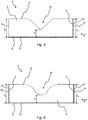
- the depression 16 of the sealing tape 2 after Fig. 3 is essentially triangular or V-shaped. In the cross-sectional view shown, the depression 16 has two legs which are essentially linear and run obliquely to planar sections of the top side of the base body 4 or the top side 6 of the sealing tape 2.
- the top 6 of the sealing tape 2 has a kink at each of the transitions to the depression 16. It goes without saying that this kink and the apex area of the depression 16 can also be rounded due to the flexibility of the soft foam of the base body 4.
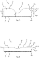
- the sealing tape 2 after Fig. 4 differs from the embodiment according to Fig. 1 in that the sealing tape 2 has a further barrier layer 18 to reduce the water vapor diffusion and / or the air permeability in the functional direction F of the sealing tape 2.
- the further barrier layer 18 is arranged in the area of the other of the first and second side flanks 10, here in the area of the second side flank 10, and completely covers a side surface 5 of the base body 4 arranged in this area in the fully expanded state of the sealing tape 2.
- the two barrier layers 18 can be designed identically.
- the barrier layers 18 can, however, also be designed differently.
- the barrier layers 18 can be formed from different materials and / or materials of different thickness, have different sealing properties or be connected to the base body 4 of the sealing tape 2 in different ways.
- one of the two barrier layers 18 can be used in accordance with the method shown in FIG Fig. 1 and 3
- the embodiment illustrated may be formed, while the other barrier layer 18 can be configured in accordance with the embodiment below with reference to FIG Fig. 5 described embodiment is formed.
- FIG. 5 illustrated sealing tape 2 differs from the sealing tape 2 according to Fig. 1 in the formation of the barrier layer 18.
- Such a barrier layer 18 can also be used with all other embodiments of the sealing tape 2.
- the barrier layer 18 has two mutually opposite edge sections 20a, 20b and a connecting section 24 formed between these edge sections.
- the edge sections 20a, 20b run in a longitudinal direction L of the sealing tape 2, which extends parallel to the underside 8 and perpendicular to the functional direction F.
- the fact that the two edge sections 20a, 20b are opposite one another relates to a state of the barrier layer 18 in which the barrier layer 18 is arranged or spread out in one plane.
- this barrier layer 18 also completely covers a side surface 5 of the base body 4 in the fully expanded state of the sealing tape 2. This can be achieved in that the edge sections 20a, 20b are arranged on the upper side 6 and the lower side 8 adjoining the side surface 5 of the base body 4.
- first edge section 20a is connected to an adjoining area of the sealing tape 2 in the area of the top 6 and the second edge section 20b is connected to an adjoining area of the sealing band 2 in the area of the underside 8.
- the first edge section 20a can, for example, be glued to the upper side of the base body 4 or laminated to it.
- the first edge section 20a can have an adhesive layer on the side facing the base body 4.
- the connection of the edge section 20a to the base body 4 can also be detachable, so that the edge section 20a can optionally be fastened to another component of the building section, such as the wall or the component, when the sealing tape 2 is installed.
- the second edge section 20b is received between an underside of the base body 4 and the adhesive layer 12, so that it is securely held there on the sealing tape 2.
- the second edge section 20b can have an adhesive layer on the side facing the base body 4 or can only be held on the base body 4 by the adhesive layer 12.
- the second edge section 20b can also be adhered to the adhesive layer 12 on an underside of the adhesive layer 12 facing away from the base body 4.
- the second edge section 20b could be detachably connected to the adhesive tape 12, so that it can optionally be attached to another component of the building section when the sealing tape 2 is installed.
- the barrier layer 18 is designed in such a way that it completely covers the side surface 5 of the base body 4. Accordingly, the barrier layer 18 has a dimension (the width) from one edge (in the area of the first edge section 20a) to the other edge (in the area of the second edge section 20b) that is at least as large as the height of the sealing tape 2 in the area of the respective side flank 10 is.
- the edge sections 20a, 20b are arranged in the area of the top and bottom 6, 8 of the sealing tape 2.
- the connecting section 24 of the barrier layer 18 then preferably has a width which corresponds at least to the height of the sealing tape 2 in the area of the respective side flank 10.
- the connecting section 24 has a width which is greater than the height h 1 in the region of the side flank 10 of the sealing tape 2 in the fully expanded state.
- barrier layers 18 When forming the barrier layers 18 in all the embodiments described herein, care should be taken to ensure that the barrier layer does not hinder the expansion of the sealing tape 2 into the completely expanded state.
- the width of the connecting portion 24 is as in FIG Fig. 5 shown greater than the height of the sealing tape in the area of the respective side flank 10, it is also prevented that the barrier layer 18 is under tension in the fully expanded state of the sealing tape 2. This would not only hinder the complete expansion of the sealing tape 2, but could also damage the barrier layer 18.
- the connecting section 24 should not be made too wide in order to avoid the formation of loops of the barrier layer 18 protruding from the base body 4 in the expanded state of the sealing tape 2, since these in turn are susceptible to damage.
- Fig. 6 is the sealing tape 2 after Fig. 5 shown in a (partially) compressed state in which it can also be wound up to form the sealing tape roll 26, as shown in FIG Fig. 2 is shown.
- the sealing tape 2 has a lower overall height.
- the height in the area of the side flanks 10 of the sealing tape 2 is less than the height h 1 or h 2 in the fully expanded state of the sealing tape 2.
- part of the barrier layer 18 is arranged along the side surface 5 of the base body 4 and the remaining part of the barrier layer 18 forms a loop 22 which is arranged in the area of the top 6 of the sealing tape 2.
- the loop 22 is received between two adjacent turns of the sealing tape roll 26 and protected from external influences.
- the loop 22 is received in the sealing tape roll 26 between the top side 6 of a turn of the sealing tape 2 and the bottom side 8 of an adjacent turn of the sealing tape 2.
- the loop 22 can also be attached to the upper side 6 of the sealing tape 2 or the base body 4.
- adhesive dots or similar connecting means can be provided between the sealing tape 2 or the base body 4 and the section of the loop 22 of the barrier layer 18 that is guided along the top.
- the loop 22 can also be formed analogously in the area of the underside 8 of the sealing tape 2.
- Embodiments are also conceivable in which a loop is formed in the area of the upper side and a loop in the area of the lower side of the sealing tape 2.
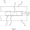
- Fig. 7 is an installation situation of the sealing tape 2 from Fig. 1 shown, which can correspondingly also be transferred to other embodiments of a sealing tape 2 according to the invention.
- the sealing tape 2 in a structural section 42, is arranged in a joint 38 between a component 14, in particular a frame profile of a window or a door, and a wall 40 in a partially compressed installation state and seals the joint 38.
- the upper side 6 of the sealing tape 2 rests against the wall 40 in the area of the side flanks 10 of the sealing tape 2, while the upper side 6 at least in the area of the original third height h 3 and in adjacent areas (between the dashed lines ) is not in contact with the wall 40.
- the third height h 3 is made larger and the upper side 6 of the sealing tape 2 thus also rests against the wall 40 in the area of the original third height h 3 , but then with a lower contact pressure than in the area of the side flanks 10 of the sealing tape 2.
- the area between the dashed lines in which the upper side 6 of the sealing tape 2 does not lie against the wall 40 or with a lower contact pressure essentially corresponds to the area of the depression 16 in the originally expanded state of the sealing tape 2.
- the barrier layer 18 extends in that it covers the entire side surface 5 of the base body 4 of the sealing tape 2, over the entire joint cross-section and offers a sealing effect against water vapor diffusion and / or air passage through the joint in the functional direction F over the entire joint cross-section.
- FIG. 8 Sealing tape 2 shown in cross section differs from the embodiment according to FIG Fig. 1 essentially in that the upper side 6 of the sealing tape 2 has an elevation 32 instead of the depression 16.
- the sealing tape 2 after Fig. 8 comprises a base body 4 made of soft foam which is resilient after compression and which is preferably impregnated for delayed resetting.
- the base body 4 is formed higher in a central area than in the areas to the right and left thereof.
- the illustrated sealing tape 2 has an upper side 6, a lower side 8 and two side flanks 10 connecting the upper side 6 and the lower side 8.
- the side flanks 10 extend essentially perpendicular to a functional direction F of the sealing tape 2, in which the sealing tape 2 in the later installed state (see FIG Fig. 12 ) is to seal a joint against air penetration and / or water vapor diffusion.
- an adhesive layer 12 is arranged which, in the example shown, runs flat and for adhesion to a component 14 (see FIG Fig. 12 ), for example a frame profile of a window or a door, is used.
- the adhesive layer 12 is preferably designed as a double-sided adhesive tape and adhered to the adjacent areas of the sealing tape 2 on its upper side.
- the adhesive layer 12 is adhered over the entire surface to the entire underside of the base body 4.
- the adhesive surface of the adhesive layer 12, which is used for attachment to the component 14, is directed downwards, ie in a direction facing away from the other components of the sealing tape 2, and is usually covered by a release film or release paper that can be removed before use.
- the top 6 of the sealing tape 2 has a profile with an elevation 32 in a central area between the side flanks 10 of the sealing tape 2. In the area of the side flanks 10, the top 6 of the sealing tape 2 is essentially flat. In the area of the elevation 32, the upper side 6 of the sealing tape 2 does not lie in a plane with these flat sections in the area of the side flanks 10, but extends from the flat areas in a direction facing away from the lower side 8.
- the upper side 6 of the sealing tape 2 is continuously curved in the area of the elevation 32.
- the upper side 6 has a curvature at the transitions between the flat sections of the upper side 6 and the elevation 32, which at a turning point continuously merges into an opposite curvature forming the apex region of the elevation 32.
- Such an elevation 32 is also described herein as an essentially U-shaped elevation 32.
- the elevation 32 can also be essentially triangular or V-shaped in that it has two legs that are essentially linear and run obliquely to the flat sections of the top side of the base body 4 or the top side 6 of the sealing tape 2.
- the sealing tape 2 In the area of the first (right) side flank 10, the sealing tape 2 has a first height h 1 in the fully expanded state, which in this embodiment corresponds to the height h 2 of the second (left) side flank 10. At the apex of the elevation 32, however, the sealing tape 2 in the fully expanded state has a fourth height h 4 which is greater than the first height h 1 and greater than the second height h 2 .
- the larger fourth height h 4 in the fully expanded state of the sealing tape 2 is formed by the elevation 32 and is preferably defined between the underside 8 of the sealing tape 2 and an apex of the elevation 32.
- the sealing tape 2 shown also has a barrier layer 18 to reduce the water vapor diffusion and / or the air permeability in the functional direction F of the sealing tape 2.
- the barrier layer 18 is arranged in the area of a first and second side flank 10, here in the area of the first side flank 10, and completely covers a side surface 5 of the base body 4 arranged in this area in the fully expanded state of the sealing tape 2.
- the barrier layer 18 extends at least from the top of the base body 4 to the underside of the base body 4.
- the barrier layer 18 can meet the adhesive layer 12, so that they preferably lie against one another in a sealing manner and thus have a barrier effect over the entire area Provide the height of the sealing tape 2.
- the barrier layer 18 preferably extends from the top 6 to the bottom 8 of the sealing tape 2 and thus over the entire height h 1 , h 2 of the sealing tape 2 in the area of the respective side flank 10.
- the barrier layer 18 thus provides the entire height for a gap-free, adjusted to a desired degree of sealing against the passage of air and / or water vapor diffusion in the functional direction F when the sealing tape is arranged in a joint in a partially compressed installation state.
- the barrier layer 18 rests over the entire surface on the side surface 5 of the base body 4 and is preferably adhered to it over the entire surface.
- the barrier layer 18 can, however, also be firmly attached to the base body 4 only in sections, for example in an area near the top and / or an area near the underside of the base body 4.
- the barrier layer 18 is preferably glued or laminated to the base body 4.
- the barrier layer 18 can also according to the method with reference to FIG Fig. 5 described embodiment be formed.
- a barrier layer 18 according to FIG. 3 can also be used in the region of the second side flank 10 Fig. 8 or the to Fig. 5 described embodiment be provided.
- Fig. 9 is the sealing tape 2 after Fig. 8 shown in a configuration wound into a roll of sealing tape 26.
- the sealing tape 2 is wound around an axis 28 to form the sealing tape roll 26 in such a way that the side flanks 10 of the sealing tape 2 form end faces 30 of the sealing tape roll 26. Consequently, the barrier layer 18 is at least partially arranged on an end face 30 of the sealing tape roll 26.
- the axis 28 preferably extends parallel to the functional direction F of the sealing tape 2 or parallel to the underside 8.
- the sealing tape 2 is preferably in a (partially) compressed state in the sealing tape roll 26, in which the upper side 6 and the lower side 8 of the sealing tape 2 run essentially in a straight line.
- the configuration as a sealing tape roll 26 is also preferred and the same relationship applies.
- the sealing tape 2 after Fig. 10 and after Fig. 11 differs from the embodiment according to Fig. 8 inter alia in the fact that the sealing tape 2 has a further barrier layer 18 to reduce the water vapor diffusion and / or the air permeability in the functional direction F of the sealing tape 2.
- the further barrier layer 18 is arranged in the area of the other of the first and second side flanks 10, here in the area of the second side flank 10, and completely covers a side surface 5 of the base body 4 arranged in this area in the fully expanded state of the sealing tape 2.
- the two barrier layers 18 can be designed identically.
- the barrier layers 18 can, however, also be designed differently.
- the barrier layers 18 can be formed from different materials and / or from materials of different thicknesses, have different sealing properties or be connected to the base body 4 of the sealing tape 2 in different ways.
- one of the two barrier layers 18 can be used in accordance with the method shown in FIG Fig. 8
- the embodiment illustrated may be formed, while the other barrier layer 18 may be formed in accordance with the embodiment with reference to Fig. 5 described embodiment is formed.
- both barrier layers 18 can also be used in accordance with FIG Fig. 5 described embodiment be formed.
- the sealing tape 2 according to the embodiments according to Figures 10 and 11 is also designed such that its surface 6 has a profile with at least one depression 16 and at least one elevation 32. With regard to the formation of the depression 16 is therefore also on the remarks on the Fig. 1 and 3 to 7 referenced, the analogous to the embodiments according to Figures 10 and 11 may apply.
- the at least one depression 16 and the at least one elevation 32 are arranged next to one another in the functional direction F.
- any number of depressions 16 and elevations 32 can be arranged next to one another in the functional direction F in a corresponding manner. It is particularly preferred that the depression 16 and the elevation 32 merge directly into one another.
- the top 6 thus has a substantially sinusoidal profile. Alternatively, however, a shoulder in the form of a flat section of the upper side 6 could also be formed between a depression 16 and an elevation 32. If the top 6 of the sealing tape has more than one depression 16 and / or more than one elevation 32, a depression 16 and an elevation 32 are preferably arranged alternately next to one another in the functional direction F.
- the first and the second height h 1 , h 2 are of different sizes, the first height h 1 being greater than the second height h 2 .
- the third height h 3 corresponds to the second height h 2 and the fourth height h 4 corresponds to the first height h 1 .
- the first side flank 10 is preferably formed in the area of an upper apex of a raised area 32 and the second side flank 10 is preferably embodied in the area of a lower apex of a depression 16.
- the first and the second side flanks 10 can, however, also be designed offset from the vertices in the functional direction F.
- the first and the second height h 1 , h 2 are the same.
- the third height h 3 is then less than the first and the second height h 1 , h 2 and the fourth height h 4 is greater than the first and the second height h 1 , h 2 .
- both the first and the second side flanks 10 are formed between the vertices of a depression 16 and an elevation 32.
- the first and second side flanks 10 can also be formed at the apexes of two depressions 16 or two elevations 32 in such a way that the first and second heights h 1 , h 2 are of the same size.
- Fig. 12 is an installation situation of the sealing tape 2 from Fig. 8 shown, which also apply to other embodiments of a sealing tape 2 according to the invention, in particular according to Figures 10 and 11 , is transferable.
- the sealing tape 2 in a structural section 42, is arranged in a joint 38 between a component 14, in particular a frame profile of a window or a door, and a wall 40 in a partially compressed installation state and seals the joint 38.
- the top 6 of the sealing tape 2 rests against the wall 40 in the area of the side flanks 10 of the sealing tape 2.
- the top 6 rests against the wall 40, but with a greater contact pressure than in the area of the side flanks 10 of the sealing tape 2.
- the area between the dashed lines in which the upper side 6 of the sealing tape 2 rests against the wall 40 with a greater contact pressure, essentially corresponds to the area of the elevation 32 in the originally expanded state of the sealing tape 2.
- the barrier layer 18 extends in that it covers the entire side surface 5 of the base body 4 of the sealing tape 2, over the entire joint cross-section and offers a sealing effect against water vapor diffusion and / or air passage through the joint in the functional direction F over the entire joint cross-section.
Landscapes
- Engineering & Computer Science (AREA)
- Civil Engineering (AREA)
- Structural Engineering (AREA)
- Architecture (AREA)
- Physics & Mathematics (AREA)
- Electromagnetism (AREA)
- Building Environments (AREA)
- Adhesive Tapes (AREA)
Priority Applications (2)
| Application Number | Priority Date | Filing Date | Title |
|---|---|---|---|
| PL19217385.4T PL3839187T3 (pl) | 2019-12-18 | 2019-12-18 | Fragment budynku z taśmą uszczelniającą |
| EP19217385.4A EP3839187B1 (fr) | 2019-12-18 | 2019-12-18 | Section de bâtiment avec bande d'étanchéité |
Applications Claiming Priority (1)
| Application Number | Priority Date | Filing Date | Title |
|---|---|---|---|
| EP19217385.4A EP3839187B1 (fr) | 2019-12-18 | 2019-12-18 | Section de bâtiment avec bande d'étanchéité |
Publications (3)
| Publication Number | Publication Date |
|---|---|
| EP3839187A1 true EP3839187A1 (fr) | 2021-06-23 |
| EP3839187C0 EP3839187C0 (fr) | 2024-03-13 |
| EP3839187B1 EP3839187B1 (fr) | 2024-03-13 |
Family
ID=68944560
Family Applications (1)
| Application Number | Title | Priority Date | Filing Date |
|---|---|---|---|
| EP19217385.4A Active EP3839187B1 (fr) | 2019-12-18 | 2019-12-18 | Section de bâtiment avec bande d'étanchéité |
Country Status (2)
| Country | Link |
|---|---|
| EP (1) | EP3839187B1 (fr) |
| PL (1) | PL3839187T3 (fr) |
Citations (8)
| Publication number | Priority date | Publication date | Assignee | Title |
|---|---|---|---|---|
| DE29813307U1 (de) * | 1998-07-27 | 1999-12-09 | SALAMANDER INDUSTRIE-PRODUKTE GMBH, 86842 TüRKHEIM | Fugendichtungskörper |
| EP2107176A1 (fr) * | 2008-03-31 | 2009-10-07 | ISO-Chemie GmbH | Bande d'étanchéité en mousse douce |
| DE102008063371A1 (de) * | 2008-12-30 | 2009-12-31 | Henkel Ag & Co. Kgaa | Vorkomprimiertes verzögert zurückstellendes Schaumstoffdichtband zur Abdichtung von Fugen zwischen Fensterrahmen und Baukörper |
| EP2297411A1 (fr) * | 2008-05-13 | 2011-03-23 | Tremco illbruck Produktion GmbH | Bandes d'etancheite en mousse |
| EP2514902A2 (fr) * | 2011-04-19 | 2012-10-24 | Tremco illbruck Produktion GmbH | Bandes étanches |
| EP2602393A2 (fr) * | 2011-12-09 | 2013-06-12 | Tremco illbruck Produktion GmbH | Bande étanche |
| DE202012101990U1 (de) * | 2012-05-23 | 2013-08-27 | Tremco Illbruck Produktion Gmbh | Dichtband |
| EP2722452A1 (fr) * | 2009-12-11 | 2014-04-23 | ISO-Chemie GmbH | Bande d'étanchéité pré-comprimée |
-
2019
- 2019-12-18 PL PL19217385.4T patent/PL3839187T3/pl unknown
- 2019-12-18 EP EP19217385.4A patent/EP3839187B1/fr active Active
Patent Citations (9)
| Publication number | Priority date | Publication date | Assignee | Title |
|---|---|---|---|---|
| DE29813307U1 (de) * | 1998-07-27 | 1999-12-09 | SALAMANDER INDUSTRIE-PRODUKTE GMBH, 86842 TüRKHEIM | Fugendichtungskörper |
| EP2107176A1 (fr) * | 2008-03-31 | 2009-10-07 | ISO-Chemie GmbH | Bande d'étanchéité en mousse douce |
| EP2297411A1 (fr) * | 2008-05-13 | 2011-03-23 | Tremco illbruck Produktion GmbH | Bandes d'etancheite en mousse |
| EP2297411B1 (fr) | 2008-05-13 | 2019-01-23 | tremco illbruck GmbH | Bandes d'étanchéité en mousse |
| DE102008063371A1 (de) * | 2008-12-30 | 2009-12-31 | Henkel Ag & Co. Kgaa | Vorkomprimiertes verzögert zurückstellendes Schaumstoffdichtband zur Abdichtung von Fugen zwischen Fensterrahmen und Baukörper |
| EP2722452A1 (fr) * | 2009-12-11 | 2014-04-23 | ISO-Chemie GmbH | Bande d'étanchéité pré-comprimée |
| EP2514902A2 (fr) * | 2011-04-19 | 2012-10-24 | Tremco illbruck Produktion GmbH | Bandes étanches |
| EP2602393A2 (fr) * | 2011-12-09 | 2013-06-12 | Tremco illbruck Produktion GmbH | Bande étanche |
| DE202012101990U1 (de) * | 2012-05-23 | 2013-08-27 | Tremco Illbruck Produktion Gmbh | Dichtband |
Also Published As
| Publication number | Publication date |
|---|---|
| EP3839187C0 (fr) | 2024-03-13 |
| EP3839187B1 (fr) | 2024-03-13 |
| PL3839187T3 (pl) | 2024-07-01 |
Similar Documents
| Publication | Publication Date | Title |
|---|---|---|
| EP2415942B1 (fr) | Bande étanche | |
| EP2333177B1 (fr) | Bande d'étanchéité pré-comprimée | |
| EP1811111B2 (fr) | Baie de fenêtre avec cadre dormant et joint d'étanchéité | |
| EP2138664B1 (fr) | Bande d'étanchéité précomprimée | |
| EP2852713B1 (fr) | Bande d'étanchéité | |
| EP3825501B1 (fr) | Bande d'étanchéité | |
| EP3608496B1 (fr) | Rouleau de bande d'étanchéité d'une bande d'étanchéité dotée de couches barrières internes | |
| DE102011000218A1 (de) | Schaumstoff-Dichtstreifen und Fensterrahmen mit Schaumstoff-Dichtstreifen | |
| EP2428632B1 (fr) | Bande d'étanchéité en mousse douce | |
| EP2666947A2 (fr) | Bande étanche | |
| EP2333178B1 (fr) | Bande d'étanchéité pré-comprimée | |
| EP3450643B2 (fr) | Rouleau de bande d'étanchéité | |
| EP2423396A2 (fr) | Bande étanche alvéolaire | |
| EP2336442B1 (fr) | Bande d'étanchéité et procédé d'équipement d'un composant pourvu d'une bande d'étanchéité | |
| EP3608480B1 (fr) | Rouleau de bande d'étanchéité d'une bande d'étanchéité dotée d'une couche barrière interne dans une direction de fonctionnement | |
| EP3650608B1 (fr) | Procédé de fabrication d'un rouleau de bande d'étanchéité | |
| EP3839187B1 (fr) | Section de bâtiment avec bande d'étanchéité | |
| EP3425132B1 (fr) | Agencement d'installation d'une bande étanche pour l'étanchéification d'un joint entre un élément de cadre et un ouvrage | |
| EP3608481B1 (fr) | Rouleau de bande d'étanchéité d'une bande d'étanchéité dotée de couches barrières internes | |
| EP3825483B1 (fr) | Bande d'étanchéité | |
| EP3825482B1 (fr) | Bande d'étanchéité | |
| EP3825484A1 (fr) | Bande d'étanchéité | |
| EP3851624B1 (fr) | Rouleau de bande d'étanchéité | |
| DE202016103401U1 (de) | Schaumstoffband |
Legal Events
| Date | Code | Title | Description |
|---|---|---|---|
| PUAI | Public reference made under article 153(3) epc to a published international application that has entered the european phase |
Free format text: ORIGINAL CODE: 0009012 |
|
| STAA | Information on the status of an ep patent application or granted ep patent |
Free format text: STATUS: THE APPLICATION HAS BEEN PUBLISHED |
|
| AK | Designated contracting states |
Kind code of ref document: A1 Designated state(s): AL AT BE BG CH CY CZ DE DK EE ES FI FR GB GR HR HU IE IS IT LI LT LU LV MC MK MT NL NO PL PT RO RS SE SI SK SM TR |
|
| STAA | Information on the status of an ep patent application or granted ep patent |
Free format text: STATUS: REQUEST FOR EXAMINATION WAS MADE |
|
| 17P | Request for examination filed |
Effective date: 20211223 |
|
| RBV | Designated contracting states (corrected) |
Designated state(s): AL AT BE BG CH CY CZ DE DK EE ES FI FR GB GR HR HU IE IS IT LI LT LU LV MC MK MT NL NO PL PT RO RS SE SI SK SM TR |
|
| STAA | Information on the status of an ep patent application or granted ep patent |
Free format text: STATUS: EXAMINATION IS IN PROGRESS |
|
| 17Q | First examination report despatched |
Effective date: 20230330 |
|
| GRAP | Despatch of communication of intention to grant a patent |
Free format text: ORIGINAL CODE: EPIDOSNIGR1 |
|
| STAA | Information on the status of an ep patent application or granted ep patent |
Free format text: STATUS: GRANT OF PATENT IS INTENDED |
|
| INTG | Intention to grant announced |
Effective date: 20231017 |
|
| GRAS | Grant fee paid |
Free format text: ORIGINAL CODE: EPIDOSNIGR3 |
|
| GRAA | (expected) grant |
Free format text: ORIGINAL CODE: 0009210 |
|
| STAA | Information on the status of an ep patent application or granted ep patent |
Free format text: STATUS: THE PATENT HAS BEEN GRANTED |
|
| AK | Designated contracting states |
Kind code of ref document: B1 Designated state(s): AL AT BE BG CH CY CZ DE DK EE ES FI FR GB GR HR HU IE IS IT LI LT LU LV MC MK MT NL NO PL PT RO RS SE SI SK SM TR |
|
| REG | Reference to a national code |
Ref country code: GB Ref legal event code: FG4D Free format text: NOT ENGLISH |
|
| REG | Reference to a national code |
Ref country code: CH Ref legal event code: EP |
|
| REG | Reference to a national code |
Ref country code: DE Ref legal event code: R096 Ref document number: 502019010780 Country of ref document: DE |
|
| REG | Reference to a national code |
Ref country code: IE Ref legal event code: FG4D Free format text: LANGUAGE OF EP DOCUMENT: GERMAN |
|
| U01 | Request for unitary effect filed |
Effective date: 20240313 |
|
| U07 | Unitary effect registered |
Designated state(s): AT BE BG DE DK EE FI FR IT LT LU LV MT NL PT SE SI Effective date: 20240321 |
|
| PG25 | Lapsed in a contracting state [announced via postgrant information from national office to epo] |
Ref country code: RS Free format text: LAPSE BECAUSE OF FAILURE TO SUBMIT A TRANSLATION OF THE DESCRIPTION OR TO PAY THE FEE WITHIN THE PRESCRIBED TIME-LIMIT Effective date: 20240613 Ref country code: HR Free format text: LAPSE BECAUSE OF FAILURE TO SUBMIT A TRANSLATION OF THE DESCRIPTION OR TO PAY THE FEE WITHIN THE PRESCRIBED TIME-LIMIT Effective date: 20240313 |
|
| PG25 | Lapsed in a contracting state [announced via postgrant information from national office to epo] |
Ref country code: ES Free format text: LAPSE BECAUSE OF FAILURE TO SUBMIT A TRANSLATION OF THE DESCRIPTION OR TO PAY THE FEE WITHIN THE PRESCRIBED TIME-LIMIT Effective date: 20240313 |
|
| REG | Reference to a national code |
Ref country code: SK Ref legal event code: T3 Ref document number: E 44173 Country of ref document: SK |
|
| PG25 | Lapsed in a contracting state [announced via postgrant information from national office to epo] |
Ref country code: RS Free format text: LAPSE BECAUSE OF FAILURE TO SUBMIT A TRANSLATION OF THE DESCRIPTION OR TO PAY THE FEE WITHIN THE PRESCRIBED TIME-LIMIT Effective date: 20240613 Ref country code: NO Free format text: LAPSE BECAUSE OF FAILURE TO SUBMIT A TRANSLATION OF THE DESCRIPTION OR TO PAY THE FEE WITHIN THE PRESCRIBED TIME-LIMIT Effective date: 20240613 Ref country code: HR Free format text: LAPSE BECAUSE OF FAILURE TO SUBMIT A TRANSLATION OF THE DESCRIPTION OR TO PAY THE FEE WITHIN THE PRESCRIBED TIME-LIMIT Effective date: 20240313 Ref country code: ES Free format text: LAPSE BECAUSE OF FAILURE TO SUBMIT A TRANSLATION OF THE DESCRIPTION OR TO PAY THE FEE WITHIN THE PRESCRIBED TIME-LIMIT Effective date: 20240313 |
|
| PG25 | Lapsed in a contracting state [announced via postgrant information from national office to epo] |
Ref country code: IS Free format text: LAPSE BECAUSE OF FAILURE TO SUBMIT A TRANSLATION OF THE DESCRIPTION OR TO PAY THE FEE WITHIN THE PRESCRIBED TIME-LIMIT Effective date: 20240713 |
|
| PG25 | Lapsed in a contracting state [announced via postgrant information from national office to epo] |
Ref country code: SM Free format text: LAPSE BECAUSE OF FAILURE TO SUBMIT A TRANSLATION OF THE DESCRIPTION OR TO PAY THE FEE WITHIN THE PRESCRIBED TIME-LIMIT Effective date: 20240313 |
|
| PG25 | Lapsed in a contracting state [announced via postgrant information from national office to epo] |
Ref country code: SM Free format text: LAPSE BECAUSE OF FAILURE TO SUBMIT A TRANSLATION OF THE DESCRIPTION OR TO PAY THE FEE WITHIN THE PRESCRIBED TIME-LIMIT Effective date: 20240313 Ref country code: RO Free format text: LAPSE BECAUSE OF FAILURE TO SUBMIT A TRANSLATION OF THE DESCRIPTION OR TO PAY THE FEE WITHIN THE PRESCRIBED TIME-LIMIT Effective date: 20240313 Ref country code: IS Free format text: LAPSE BECAUSE OF FAILURE TO SUBMIT A TRANSLATION OF THE DESCRIPTION OR TO PAY THE FEE WITHIN THE PRESCRIBED TIME-LIMIT Effective date: 20240713 |
|
| REG | Reference to a national code |
Ref country code: DE Ref legal event code: R097 Ref document number: 502019010780 Country of ref document: DE |
|
| PLBE | No opposition filed within time limit |
Free format text: ORIGINAL CODE: 0009261 |
|
| STAA | Information on the status of an ep patent application or granted ep patent |
Free format text: STATUS: NO OPPOSITION FILED WITHIN TIME LIMIT |
|
| U20 | Renewal fee for the european patent with unitary effect paid |
Year of fee payment: 6 Effective date: 20241227 |
|
| 26N | No opposition filed |
Effective date: 20241216 |
|
| PG25 | Lapsed in a contracting state [announced via postgrant information from national office to epo] |
Ref country code: MC Free format text: LAPSE BECAUSE OF FAILURE TO SUBMIT A TRANSLATION OF THE DESCRIPTION OR TO PAY THE FEE WITHIN THE PRESCRIBED TIME-LIMIT Effective date: 20240313 |
|
| PG25 | Lapsed in a contracting state [announced via postgrant information from national office to epo] |
Ref country code: IE Free format text: LAPSE BECAUSE OF NON-PAYMENT OF DUE FEES Effective date: 20241218 |
|
| REG | Reference to a national code |
Ref country code: CH Ref legal event code: U11 Free format text: ST27 STATUS EVENT CODE: U-0-0-U10-U11 (AS PROVIDED BY THE NATIONAL OFFICE) Effective date: 20260101 |
|
| PGFP | Annual fee paid to national office [announced via postgrant information from national office to epo] |
Ref country code: GB Payment date: 20251229 Year of fee payment: 7 |
|
| PGFP | Annual fee paid to national office [announced via postgrant information from national office to epo] |
Ref country code: CZ Payment date: 20251126 Year of fee payment: 7 |
|
| PGFP | Annual fee paid to national office [announced via postgrant information from national office to epo] |
Ref country code: PL Payment date: 20251126 Year of fee payment: 7 |
|
| PGFP | Annual fee paid to national office [announced via postgrant information from national office to epo] |
Ref country code: SK Payment date: 20251126 Year of fee payment: 7 |
|
| U20 | Renewal fee for the european patent with unitary effect paid |
Year of fee payment: 7 Effective date: 20251229 |
|
| PGFP | Annual fee paid to national office [announced via postgrant information from national office to epo] |
Ref country code: CH Payment date: 20260101 Year of fee payment: 7 |
|
| PG25 | Lapsed in a contracting state [announced via postgrant information from national office to epo] |
Ref country code: CY Free format text: LAPSE BECAUSE OF FAILURE TO SUBMIT A TRANSLATION OF THE DESCRIPTION OR TO PAY THE FEE WITHIN THE PRESCRIBED TIME-LIMIT Effective date: 20240313 |