EP3839202A2 - Werkzeugidentifikation - Google Patents
Werkzeugidentifikation Download PDFInfo
- Publication number
- EP3839202A2 EP3839202A2 EP21155708.7A EP21155708A EP3839202A2 EP 3839202 A2 EP3839202 A2 EP 3839202A2 EP 21155708 A EP21155708 A EP 21155708A EP 3839202 A2 EP3839202 A2 EP 3839202A2
- Authority
- EP
- European Patent Office
- Prior art keywords
- tool
- identification
- top drive
- unit
- reader
- Prior art date
- Legal status (The legal status is an assumption and is not a legal conclusion. Google has not performed a legal analysis and makes no representation as to the accuracy of the status listed.)
- Granted
Links
Images


Classifications
-
- E—FIXED CONSTRUCTIONS
- E21—EARTH OR ROCK DRILLING; MINING
- E21B—EARTH OR ROCK DRILLING; OBTAINING OIL, GAS, WATER, SOLUBLE OR MELTABLE MATERIALS OR A SLURRY OF MINERALS FROM WELLS
- E21B19/00—Handling rods, casings, tubes or the like outside the borehole, e.g. in the derrick; Apparatus for feeding the rods or cables
-
- E—FIXED CONSTRUCTIONS
- E21—EARTH OR ROCK DRILLING; MINING
- E21B—EARTH OR ROCK DRILLING; OBTAINING OIL, GAS, WATER, SOLUBLE OR MELTABLE MATERIALS OR A SLURRY OF MINERALS FROM WELLS
- E21B17/00—Drilling rods or pipes; Flexible drill strings; Kellies; Drill collars; Sucker rods; Cables; Casings; Tubings
- E21B17/006—Accessories for drilling pipes, e.g. cleaners
-
- E—FIXED CONSTRUCTIONS
- E21—EARTH OR ROCK DRILLING; MINING
- E21B—EARTH OR ROCK DRILLING; OBTAINING OIL, GAS, WATER, SOLUBLE OR MELTABLE MATERIALS OR A SLURRY OF MINERALS FROM WELLS
- E21B19/00—Handling rods, casings, tubes or the like outside the borehole, e.g. in the derrick; Apparatus for feeding the rods or cables
- E21B19/02—Rod or cable suspensions
-
- E—FIXED CONSTRUCTIONS
- E21—EARTH OR ROCK DRILLING; MINING
- E21B—EARTH OR ROCK DRILLING; OBTAINING OIL, GAS, WATER, SOLUBLE OR MELTABLE MATERIALS OR A SLURRY OF MINERALS FROM WELLS
- E21B19/00—Handling rods, casings, tubes or the like outside the borehole, e.g. in the derrick; Apparatus for feeding the rods or cables
- E21B19/14—Racks, ramps, troughs or bins, for holding the lengths of rod singly or connected; Handling between storage place and borehole
-
- E—FIXED CONSTRUCTIONS
- E21—EARTH OR ROCK DRILLING; MINING
- E21B—EARTH OR ROCK DRILLING; OBTAINING OIL, GAS, WATER, SOLUBLE OR MELTABLE MATERIALS OR A SLURRY OF MINERALS FROM WELLS
- E21B3/00—Rotary drilling
- E21B3/02—Surface drives for rotary drilling
- E21B3/022—Top drives
-
- E—FIXED CONSTRUCTIONS
- E21—EARTH OR ROCK DRILLING; MINING
- E21B—EARTH OR ROCK DRILLING; OBTAINING OIL, GAS, WATER, SOLUBLE OR MELTABLE MATERIALS OR A SLURRY OF MINERALS FROM WELLS
- E21B41/00—Equipment or details not covered by groups E21B15/00 - E21B40/00
-
- E—FIXED CONSTRUCTIONS
- E21—EARTH OR ROCK DRILLING; MINING
- E21B—EARTH OR ROCK DRILLING; OBTAINING OIL, GAS, WATER, SOLUBLE OR MELTABLE MATERIALS OR A SLURRY OF MINERALS FROM WELLS
- E21B47/00—Survey of boreholes or wells
- E21B47/12—Means for transmitting measuring-signals or control signals from the well to the surface, or from the surface to the well, e.g. for logging while drilling
- E21B47/13—Means for transmitting measuring-signals or control signals from the well to the surface, or from the surface to the well, e.g. for logging while drilling by electromagnetic energy, e.g. radio frequency
-
- E—FIXED CONSTRUCTIONS
- E21—EARTH OR ROCK DRILLING; MINING
- E21B—EARTH OR ROCK DRILLING; OBTAINING OIL, GAS, WATER, SOLUBLE OR MELTABLE MATERIALS OR A SLURRY OF MINERALS FROM WELLS
- E21B19/00—Handling rods, casings, tubes or the like outside the borehole, e.g. in the derrick; Apparatus for feeding the rods or cables
- E21B19/02—Rod or cable suspensions
- E21B19/04—Hooks
-
- E—FIXED CONSTRUCTIONS
- E21—EARTH OR ROCK DRILLING; MINING
- E21B—EARTH OR ROCK DRILLING; OBTAINING OIL, GAS, WATER, SOLUBLE OR MELTABLE MATERIALS OR A SLURRY OF MINERALS FROM WELLS
- E21B19/00—Handling rods, casings, tubes or the like outside the borehole, e.g. in the derrick; Apparatus for feeding the rods or cables
- E21B19/02—Rod or cable suspensions
- E21B19/06—Elevators, i.e. rod- or tube-gripping devices
- E21B19/07—Slip-type elevators
-
- G—PHYSICS
- G06—COMPUTING OR CALCULATING; COUNTING
- G06K—GRAPHICAL DATA READING; PRESENTATION OF DATA; RECORD CARRIERS; HANDLING RECORD CARRIERS
- G06K7/00—Methods or arrangements for sensing record carriers, e.g. for reading patterns
- G06K7/10—Methods or arrangements for sensing record carriers, e.g. for reading patterns by electromagnetic radiation, e.g. optical sensing; by corpuscular radiation
- G06K7/10009—Methods or arrangements for sensing record carriers, e.g. for reading patterns by electromagnetic radiation, e.g. optical sensing; by corpuscular radiation sensing by radiation using wavelengths larger than 0.1 mm, e.g. radio-waves or microwaves
- G06K7/10366—Methods or arrangements for sensing record carriers, e.g. for reading patterns by electromagnetic radiation, e.g. optical sensing; by corpuscular radiation sensing by radiation using wavelengths larger than 0.1 mm, e.g. radio-waves or microwaves the interrogation device being adapted for miscellaneous applications
Definitions
- the present disclosure generally relates to apparatus and methods for tool identification during a well operation. More particularly, the present disclosure relates to apparatus and method for automatic tool identification in a modular top drive system.
- a wellbore is formed to access hydrocarbon-bearing formations (e.g., crude oil and/or natural gas) or for geothermal power generation by drilling.
- Drilling is accomplished by utilizing a drill bit that is mounted on the end of a drill string.
- the drill string is connected to a top drive on a surface rig by a drilling tool and rotated by the top drive.
- the drilling tool, drill string and drill bit are removed from the top drive.
- a casing tool is then attached to the top drive to lower a section of casing into the wellbore. An annulus is thus formed between the casing string and the formation.
- the casing string may then be hung from the wellhead.
- the casing tool may then be replaced by a cementing tool to conduct a cementing operation to fill the annulus with cement.
- the casing string is cemented into the wellbore by circulating cement into the annulus defined between the outer wall of the casing and the borehole.
- the combination of cement and casing strengthens the wellbore and facilitates the isolation of certain areas of the formation behind the casing for the production of hydrocarbons.
- the tool exchange during drilling, casing, and cementing modes usually requires personnel to identify the correct tool and to work at heights on the rig thus is time consuming and dangerous.
- the present disclosure generally relates to apparatus and methods for automatic tool identification in a modular top drive system.
- the modular top drive system may include an identification reader for automatically identifying tools during operation for rig up and tool exchange.
- the identification reader may be disposed in one of a tool storage unit, a tool change unit or a top drive unit. Drilling tools, cementing tools and casing tools with one or more identification devices may be used with the modular top drive system.
- the one or more identification devices may be radio frequency identification devices, barcodes, such as linear barcodes and matrix barcodes, text tags, micro-controllers, or combinations thereof.
- One embodiment of the present disclosure provides a method for operating a modular top drive system.
- the method includes positioning a tool within a range of an identification reader, reading one or more identification devices on the tool using the identification reader to identify the tool, configuring a top drive unit according to the identification of the tool, and engaging the tool to a top drive unit.
- FIG. 1 Another embodiment provides a modular top drive system including a top drive unit for selectively connecting to a tool, an identification reader configured to obtain identity information from identification devices, and a central control unit connectable to the top drive unit and the identification reader.
- the modular top drive system comprises a top drive unit for selectively connecting to a tool by a friction structure, such as slips, or by a weight bearing shoulder, such as a shoulder having a latch profile, and an identification reader, wherein the identification reader is configured to obtain identity information from identification devices on tools.
- Another embodiment provides a method for operating a modular top drive system.
- the method includes positioning a tool within a range of an identification reader, reading one or more identification devices on the tool using the tool identification reader to confirm the tool is the correct tool; and engaging the tool to a top drive unit.
- the tool includes a coupling for connecting to a top drive by a friction structure, or a weight bearing shoulder, and one or more identification devices including identification information.
- the top drive unit for construction of a wellbore.
- the top drive unit includes a drive body, a drive motor having a stator connected to the drive body, a coupler torsionally connected to a rotor of the drive motor for selectively connecting a tool, and an identification reader to obtain identity information of an identification device on the tool.
- the tool change unit includes a tool holder configured to lift a tool, a drive assembly configured to move the tool holder, and an identification reader to obtain identity information from an identification device on the tool.
- the tool storage unit includes a frame having one or more parking spots, and an identification reader to obtain identity information from identification devices on tools in the parking spots.
- Each parking spot is configured to receive one of a drilling tool, a casing tool, a cementing tool, a fracturing tool, a pump, a sand screen, a clamping tool, an internal gripping tool, an external gripping tool, an adaptor, or a combination thereof.
- FIG. 1 schematically illustrates a modular top drive system 100 according to one embodiment of the present disclosure.
- the modular top drive system 100 may include a top drive unit 102, a tool storage unit 104, and a tool change unit 106.
- the modular top drive system 100 may further include a central control unit 108 connected to at least one of the top drive unit 102, the tool storage unit 104, or the tool change unit 106.
- the central control unit 108 is connected to all of the top drive unit 102, the tool storage unit 104, and the tool change unit 106.
- the modular top drive system 100 may be used in on a drilling rig 10 for a well operation.
- the top drive unit 102 may be mounted on a derrick 14 on a rig floor 12.
- a plurality of tools may be exchangeably attached to the top drive unit 102 to perform various operations.
- a drilling tool 110 may be attached to the top drive unit 102 for drilling
- a casing tool 112 may be attached to the top drive unit 102 for installing casing to the wellbore
- a cementing tool 114 may be attached to the top drive unit 102 to perform cementing
- accessories 116 may be used to perform other operations.
- the tool storage unit 104 and the tool change unit 106 may be disposed on a deck 20.
- a plurality of tools such as the drilling tool 110, the casing tool 112, the cementing tool 114, and the accessories 116, may be stored in the tool storage unit 104 when not in use.
- the tool change unit 106 is configured to transfer the plurality of tools between the tool storage unit 104 and the top drive unit 102.
- the plurality of tools may include a universal coupling so that each of the plurality of tools can be interchangeably connected to the top drive unit 102, stored in the tool storage unit 104, and handled by the tool change unit 106.
- the plurality of tools may include any suitable tools, such as completion tools, fracturing tools, pumps, sand screens, clamping tools, internal gripping tools, external gripping tools, adaptors, or combinations thereof.
- one or more of the plurality of tools may include an identification device that may be used to store identify information of the tool.
- the identification device may also be used to store additional information, such as operational parameters and/or operation history of the tool.
- At least one of the tool storage unit 104, the top drive unit 102, and the tool change unit 106 includes a reading device configured to interact with the tool identification device and retrieve information to identify the tool.
- identification of the tools may be transmitted to the central control unit 108 by the top drive unit 102, the tool storage unit 104 or the tool change unit 106.
- the central control unit 108 may use the identification of the tools to control the operation, for example to control an automatic tool exchange process.
- the top drive unit 102 may include a coupling unit 120 configured to selectively connect and operate one or more tools, such as the drilling tool 110, the casing tool 112, the cementing tool 114.
- the top drive unit 102 may include a trolley (not shown) configured to couple the coupling unit 120 to a rail 124 on the derrick 14.
- the top drive unit 102 may include a tool identifying device 126.
- the tool identifying device 126 may be configured to interact with the identification device in each tool connected to the top drive unit 102 or each tool to be connected to the top drive unit 102.
- the tool storage unit 104 may include a frame 140 and a plurality of tool receiving slots 142. Each of the tool receiving slots 142 may be configured to receive a tool. In one embodiment, each tool receiving slots 142 may include a coupling profile for receiving a tool. The coupling profile in each tool receiving slot 142 may be the same as the coupling profile in the top drive unit 102. In one embodiment, the tool storage unit 104 may further include a tool identifying device 144 configured to identify tools disposed in the tool storage unit 104.
- the tool change unit 106 may include a base 160.
- the base 160 may be secured to the deck 20 of the drilling rig 10 or adjacent structures.
- a post 162 may extend from the base 160.
- the post 162 may extend vertically from the base 160 to a height above the rig floor 12 such that the tool change unit 106 may retrieve any of the tools from the tool storage unit 104 and deliver the retrieved tools to the top drive unit 102 and vice versa.
- the tool change unit 106 further includes a slide hinge 166 connected to the post 162, and an arm 164 connected to the slide hinge 166.
- the slide hinge 166 may be connected to the post 162 by a linear actuator that moves the slide hinge 166 longitudinally along the post 162.
- the slide hinge 166 may also be pivotally connected to the linear actuator allowing pivoting of the arm 164 relative to the post 162.
- the linear actuator may include an electric slew motor, a hydraulic slew motor, or an electro-mechanical linear actuator.
- the arm 164 may include an aft-arm 172, a forearm 170, and an actuated joint 168 connecting the forearm 170 and the aft-arm 172.
- a tool holder 174 may be releasably connected to the forearm 170.
- the arm 164 may further include an arm actuator (not shown) for selectively curling and extending the forearm 170 and relative to the aft-arm 172.
- the arm actuator may include a cylinder and a piston disposed in a bore of the cylinder.
- the arm actuator may include an electro-mechanical linear actuator, such as a motor and lead screw or pinion and gear rod, instead of the piston and cylinder assembly.
- the actuated joint may be a telescopic joint instead of an elbow.
- the tool change unit 106 may include a tool identifying device 176.
- the tool identifying device 176 may be disposed near the tool holder 174 to identify tools engaged by the tool holder 174 or adjacent the tool holder 174.
- the modular top drive system 100 may include a traditional tool handling equipment, such as a crane, a stabmaster lift, a telescoping lift, or the likes, in place of the tool change unit 106 to transfer the plurality of tools between the tool storage unit 104 and the top drive unit 102.
- a traditional tool handling equipment such as a crane, a stabmaster lift, a telescoping lift, or the likes
- the modular top drive system 100 is not equipped with the tool storage unit 104.
- One or more tools may be stored in convenient locations on the rig.
- the modular top drive system 100 is not equipment with the tool storage unit 104 and the tool change unit 106.
- a tool to be installed on the top drive unit 102 may be transported to the deck using traditional equipment, such as a manually controlled crane, a stabmaster lift, a telescoping tool, and secured to the slips on the deck.
- the top drive unit 102 may then move down towards the slips to connect with the tool on the slips.
- the top drive unit 102 may move down towards the slips on the deck to set the tool on the slips and release the tool.
- the modular top drive system 100 may be configured to read identification devices of a plurality of tools consistently or periodically so that identifications and/or locations of the plurality of tools are available all the time to different units.
- identification, location, and/or other information of the plurality of tools may be stored in a database in the central control unit 108.
- the database may be updated when the identification devices on the plurality of tools are read by various readers.
- the identification devices on a tool is read each time the tool enters into the range of one of the reader, such as the readers in the tool storage unit 104, by the readers in the tool change unit 106, or by the readers in the top drive unit 102.
- the location of the tool may be determined by location of the reader that makes the latest reading of the tool.
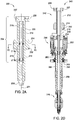
- Figure 2A is schematic sectional view of a drilling tool 200 having an identification device 202.
- the drilling tool 200 may be used in place of the drilling tool 110 in the modular top drive system 100.
- the drilling tool 200 may include a coupling 204 and a quill 206 extended from the coupling 204.
- the coupling 204 may include a head 208 having an external profile 210 for latching with the top drive unit 102, the tool storage unit 104, or the tool change unit 106.
- the external profile 210 is a bayonet profile as shown in Figure 2B .
- the bayonet profile may have one or more external prongs 210p and prong-ways 210w spaced around the head 208 at regular intervals.
- the top drive unit 102 may include a mating bayonet profile having one or more internal prongs and prong-ways spaced at regular intervals.
- the coupling 204 may be designed to connect with a top drive unit by other suitable mechanism, such as by a friction structure, such as slips, by a load bearing head, or by a threaded connection.
- the head 208 may also have one or more locking slots 207.
- the locking slots 207 may receive locking pins from a drive unit, such as the top drive unit 102, during operation so that the drilling tool 200 may be secured attached to the drive unit to receive torque from the drive unit.
- the locking slots 207 may be formed in suitable locations and/or arranged in a pattern to match with a coupler in a drive unit.
- the coupling 204 further include a neck 212 extending from the head 208.
- the neck 212 has a reduced diameter relative to a maximum outer diameter of the head 208 to allow the coupling 204 to extend through the length of the internal bayonet in the top drive unit 102.
- the coupling 204 may further include a lifting shoulder 214 connected to a lower end of the neck 212.
- the lifting shoulder 214 has an enlarged diameter relative to the reduced diameter of the neck 212.
- a torso 216 having a reduced diameter relative to the lifting shoulder 214 may extend from the lifting shoulder 214.
- the torso 216 may have a length corresponding to a length of the tool holder 174 of the tool change unit 106 so that a bottom of the lifting shoulder 214 may seat on a top of the tool holder 174 for transport between the tool storage unit 104 to the top drive unit 102.
- the quill 206 may be a shaft having an upper end connected to the torso 216.
- the quill 206 may have a bore formed therethrough and a threaded coupling, such as a pin, formed at a lower end thereof.
- the drilling tool 200 may further include an internal blowout preventer (IBOP) 218.
- the IBOP 218 may include an internal sleeve 218v and one or more shutoff valves 218u and 218b. Each shutoff valve 218u, 218b may be actuated.
- the drilling tool 200 may have one or more hydraulic passages 220 formed therein.
- the hydraulic passage 220 may be used to provide fluid communication between HPU manifold and hydraulic devices, such as hydraulic swivel or control lines.
- the identification device 202 may be attached to an outer surface of the drilling tool 200, for example by adhesives. Alternatively, the identification device 202 may be disposed in a recessed space for secure attachment. Alternatively, the identification device 202 may be embedded inside the drilling tool 200 when the identification device 202 does not require direct line of sight to interact with a corresponding identification reader.
- the identification device 202 may be disposed on the lifting shoulder 214 of the drilling tool 200 in Figure 2A . Alternatively, the identification device 202 may be disposed in any suitable locations on the drilling tool 200. For example, the identification device 202 may be disposed on the coupling 204.
- the identification device 202 may be a radio frequency identification device (RFID), such as a RFID tag or a RFID chip.
- RFID radio frequency identification device
- the RFID includes preloaded information and data for automatic identification. Preloaded information and data in the RFID may be read by a RFID reader nearby. The RFID may be read by a RFID reader without requiring a direct line of sight.
- the identification device 202 may be a standard RFID tag with an Electronic Product Code (EPC) printed thereon by a RFID printer.
- EPC code includes a product serial number which may be used to retrieve detailed information from a database, such as a database in the central control unit 108 of the modular top drive system 100.
- the identification device 202 may be a custom made RFID chip which includes custom data set used by a special identification process.
- the RFID chip may be read-only or re-writable.
- the RFID chip may include operating history in addition to product information.
- the identification device 202 may be a passive RFID that does not include or is not connected to an electrical power source.
- the passive RFID may collect energy from interrogating radio waves from a reader nearby and act as a passive transponder to send preloaded information and data to the reader.
- the identification device 202 of Figure 2A is a passive device without a power source. Passive identification devices are easy to maintain and may be read anywhere.
- the identification device 202 may include a power source, such as a battery or a connection to an external power source.
- the drilling tool 200 may include two or more identification devices 202 positioned at various locations. Two or more identification devices 202 may be used to prevent blind spots in an identification reader so that the drilling tool 200 can be identified at any relative positions between the reader and the drilling tool 200. The two or more identification devices 202 may be disposed at different areas of the drilling tool 200. For example, one or more identification devices 202 may be disposed on the lifting shoulder 214 and one or more identification devices may be disposed on the coupling 204.
- Figure 2C is a schematic sectional view of the drilling tool 200 showing distribution of multiple identification devices 202.
- the drilling tool 200 includes four identification devices 202 distributed along an outer surface 214o of the lifting shoulder 214.
- the four identification devices 202 may be positioned at 90 degrees apart from each other. This arrangement of identification devices 202 ensures that at least one of the identification devices 202 is within a range of a reader regardless of the orientation of the drilling tool 200 relative to a central axis 201.
- FIG. 2D is schematic sectional view of a casing tool 240 according to one embodiment of the present disclosure.
- the casing tool 240 may be used in place of the casing tool 112 in the modular top drive system 100.
- the casing tool 240 includes a coupling 242, a spear 244, and a fill up tool 246.
- the coupling 242 is similar to the coupling 204 of the drilling tool 200.
- the coupling 242 allows the casing tool 240 to selectively attach to the top drive unit 102, store in the tool storage unit 104, and to be handled by the tool change unit 106.
- the coupling 242 includes one or more identification devices 202 so that the casing tool 240 can be identified by the top drive unit 102, the tool storage unit 104, and/or the tool change unit 106.
- the coupling 242 includes an adapter 248 extending from the torso 216 for connection with the spear 244.
- the adapter 248 may have a bore formed therethrough.
- the adapter 248 may include an outer thread and an inner receptacle formed at a lower end thereof.
- the spear 244 may include a linear actuator 250, a bumper 252, a collar 254, a mandrel 256, a set of grippers, such as slips 258, a seal joint 260, and a sleeve 262.
- the collar 254 may have an inner thread formed at each longitudinal end thereof.
- the collar upper thread may be engaged with the outer thread of the adapter 248, thereby connecting the coupling 242 and the spear 244.
- the collar lower thread may be engaged with an outer thread formed at an upper end of the mandrel 256 and the mandrel may have an outer flange formed adjacent to the upper thread and engaged with a bottom of the collar 254, thereby connecting the mandrel 256 and the collar 254.
- the seal joint 260 may include the inner barrel, an outer barrel, and a nut.
- the inner barrel may have an outer thread engaged with a threaded portion of the shaft receptacle and an outer portion carrying a seal engaged with a seal bore portion of the shaft receptacle.
- the mandrel 256 may have a bore formed therethrough and an inner receptacle formed at an upper portion thereof and in communication with the bore.
- the mandrel receptacle may have an upper conical portion, a threaded mid portion, and a recessed lower portion.
- the outer barrel may be disposed in the recessed portion of the mandrel 256 and trapped therein by engagement of an outer thread of the nut with the threaded mid portion of the mandrel receptacle.
- the outer barrel may have a seal bore formed therethrough and a lower portion of the inner barrel may be disposed therein and carry a stab seal engaged therewith.
- the linear actuator 250 may include a housing, an upper flange, a plurality of piston and cylinder assemblies, and a lower flange.
- the housing may be cylindrical, may enclose the cylinders of the assemblies, and may be connected to the upper flange, such as by fastening.
- the collar 254 may also have an outer thread formed at the upper end thereof.
- the upper flange may have an inner thread engaged with the outer collar thread, thereby connecting the two members.
- Each flange may have a pair of lugs for each piston and cylinder assembly connected, such as by fastening or welding, thereto and extending from opposed surfaces thereof.
- Each cylinder of the linear actuator 250 may have a coupling, such as a hinge knuckle, formed at an upper end thereof.
- the upper hinge knuckle of each cylinder may be received by a respective pair of lugs of the upper flange and pivotally connected thereto, such as by fastening.
- Each piston of the linear actuator 250 may have a coupling, such as a hinge knuckle, formed at a lower end thereof.
- Each piston of the linear actuator 250 may be disposed in a bore of the respective cylinder.
- the piston may divide the cylinder bore into a raising chamber and a lowering chamber and the cylinder may have ports formed through a wall thereof and each port may be in fluid communication with a respective chamber.
- the sleeve 262 may have an outer shoulder formed in an upper end thereof trapped between upper and lower retainers.
- a washer may have an inner shoulder formed in a lower end thereof engaged with a bottom of the lower retainer.
- the washer may be connected to the lower flange, such as by fastening, thereby longitudinally connecting the sleeve 262 to the linear actuator 250.
- the sleeve 262 may also have one or more (pair shown) slots formed through a wall thereof at an upper portion thereof.
- the bumper 252 may be connected to the mandrel, such as by one or more threaded fasteners, each fastener extending through a hole thereof, through a respective slot of the sleeve 262, and into a respective threaded socket formed in an outer surface of the mandrel 256, thereby also torsionally connecting the sleeve to the mandrel while allowing limited longitudinal movement of the sleeve relative to the mandrel to accommodate operation of the slips 258.
- a lower portion of the spear 244 may be stabbed into a casing joint until the bumper 252 engages a top of the casing joint.
- the sleeve 262 may extend along the outer surface of the mandrel from the lower flange of the linear actuator 250 to the slips 258.
- a lower end of the sleeve 262 may be connected to upper portions of each of the slips 258, such as by a flanged (i.e., T-flange and T-slot) connection.
- Each slip 258 may be radially movable between an extended position and a retracted position by longitudinal movement of the sleeve 262 relative to the slips.
- a slip receptacle may be formed in an outer surface of the mandrel 256 for receiving the slips 258.
- the slip receptacle may include a pocket for each slip 258, each pocket receiving a lower portion of the respective slip.
- the mandrel 256 may be connected to lower portions of the slips 258 by reception thereof in the pockets.
- Each slip pocket may have one or more inclined surfaces formed in the outer surface of the mandrel 256 for extension of the respective slip.
- a lower portion of each slip 258 may have one or more inclined inner surfaces corresponding to the inclined slip pocket surfaces.
- each slip 258 may also have a guide profile, such as tabs, extending from sides thereof.
- Each slip pocket may also have a mating guide profile, such as grooves, for retracting the slips 258 when the sleeve 262 moves upward away from the slips.
- Each slip 258 may have teeth formed along an outer surface thereof.
- the fill up tool 246 may include a flow tube, a stab seal, such as a cup seal, a release valve, and a mud saver valve.
- the cup seal may have an outer diameter slightly greater than an inner diameter of the casing joint to engage the inner surface thereof during stabbing of the spear 244 therein.
- the cup seal may be directional and oriented such that pressure in the casing bore energizes the seal into engagement with the casing joint inner surface.
- An upper end of the flow tube may be connected to a lower end of the mandrel 256, such as by threaded couplings.
- the mud saver valve may be connected to a lower end of the flow tube, such as by threaded couplings.
- the cup seal and release valve may be disposed along the flow tube and trapped between a bottom of the mandrel and a top of the mudsaver valve.
- the spear 244 may be capable of supporting weight of a casing string.
- the string weight may be transferred to the top drive unit 102 via the slips 258, the mandrel 256, the collar 254, the adapter 248, and the coupling 242.
- Fluid may be injected into the casing string attached to the casing tool 240 via the coupling 242, the adapter 248, the seal joint 260, the mandrel 256, the flow tube, and the mud saver valve.
- the spear 244 may thus have a load path separated from a flow path at the interface between the adapter 248 and the collar 254 and at the interface between the collar and the mandrel 256. This separation allows for more robust connections between the adapter 248 and the collar 254 and between the collar and the mandrel 256 than if the connections therebetween had to serve both load and isolation functions.
- FIG 2E is schematic sectional view of a cementing tool 270 according to one embodiment of the present disclosure.
- the cementing tool 270 may be used in place of the cementing tool 114 in the modular top drive system 100.
- the cementing tool 270 may include a coupling 272 and a cementing head 274.
- the coupling 272 is similar to the coupling 204 of the drilling tool 200.
- the coupling 272 allows the cementing tool 270 to selectively attach to the top drive unit 102, store in the tool storage unit 104, and to be handled by the tool change unit 106.
- the coupling 272 includes one or more identification devices 202 so that the cementing tool 270 can be identified by the top drive unit 102, the tool storage unit 104, and/or the tool change unit 106.
- the coupling 272 includes a quill 275 extending from the torso 216 for connection with the cementing head 274.
- the cementing head 274 may include a cementing swivel 276, a launcher 278, and a release plug, such as a dart 280.
- the cementing swivel 276 may include a bar 282 for connecting with a drive body.
- the cementing swivel 276 may further include a mandrel and bearings for supporting the housing from the mandrel while accommodating rotation of the mandrel. An upper end of the mandrel may be connected to a lower end of the quill 275, such as by threaded couplings.
- the cementing swivel 276 may further include an inlet formed through a wall of the housing and in fluid communication with a port formed through the mandrel and a seal assembly for isolating the inlet-port communication.
- the mandrel port may provide fluid communication between a bore of the cementing head 274 and the housing inlet.
- the launcher 278 may include a body, a deflector, a canister, a gate, the actuator, and an adapter.
- the body may be tubular and may have a bore therethrough.
- An upper end of the body may be connected to a lower end of the cementing swivel 276, such as by threaded couplings, and a lower end of the body may be connected to the adapter, such as by threaded couplings.
- the canister and deflector may each be disposed in the body bore.
- the deflector may be connected to the cementing swivel mandrel, such as by threaded couplings.
- the canister may be longitudinally movable relative to the body.
- the canister may be tubular and have ribs formed along and around an outer surface thereof. Bypass passages (only one shown) may be formed between the ribs.
- the canister may further have a landing shoulder formed in a lower end thereof for receipt by a landing shoulder of the adapter.
- the deflector may be operable to divert fluid received from a cement line away from a bore of the canister and toward the bypass passages.
- the adapter may have a threaded coupling, such as a threaded pin, formed at a lower end thereof for connection to a work string.
- the dart 280 may be disposed in the canister bore.
- the dart 280 may be made from one or more drillable materials and include a finned seal and mandrel.
- the mandrel may be made from a metal or alloy and may have a landing shoulder and carry a landing seal for engagement with the seat and seal bore of a wiper plug (not shown) of the work string.
- the gate of the launcher 278 may include a housing, a plunger, and a shaft.
- the housing may be connected to a respective lug formed in an outer surface of the body, such as by threaded couplings.
- the plunger may be radially movable relative to the body between a capture position and a release position. The plunger may be moved between the positions by a linkage, such as a jackscrew, with the shaft.
- the shaft may be connected to and rotatable relative to the housing.
- the actuator may be a hydraulic motor operable to rotate the shaft relative to the housing.
- the actuator may include a reservoir (not shown) for receiving the spent hydraulic fluid or the cementing head 274 may include a second actuator swivel and hydraulic conduit (not shown) for returning the spent hydraulic fluid to a HPU.
- FIG. 3A is schematic sectional view of a drilling tool 300 according to one embodiment of the present disclosure.
- the drilling tool 300 is similar to the drilling tool 200 except that the drilling tool 300 includes one or more identification labels 302 attached thereon.
- Each identification label 302 may include barcode and/or text containing identity information of the drilling tool 300.
- each identification label 302 may include linear barcodes.
- each identification label 302 may include matrix barcodes.
- the identification labels 302 are passive at all times producing no interference to other identification devices on the same tool or identification devices on tools nearby.
- the identification label 302 may include identity information of the drilling tool 300 in the form of a product code, a product model, and/or a product name.
- detailed information such as operating parameters and operating history, may be stored in a data storage unit in a controller, such as the central control unit 108 in Figure 1 .
- the detailed information of the drilling tool 300 may be retrieved from the data storage unit once the identity information is abstracted from the identification label 302 by a reader.
- the identification label 302 may be read by a barcode reader, such as a linear barcode reader or a matrix barcode reader, a camera, a camera with optical character recognition (OCR) software, or any suitable optical readers.
- the identification label 302 may be read when positioned in direct line of sight of a reader.
- the drilling tool 300 may include a plurality of identification labels 302 attached to various locations on exterior of the drilling tool 300.
- the plurality of identification labels 302 may be positioned to allow the drilling tool 300 be identified regardless of the position and orientation.
- a plurality of identification labels 302 may be attached to an outer surface 304 of the lifting shoulder 214.
- the plurality of identification labels 302 may be positioned at equal intervals on the outer surface 304.
- identification labels 302 may be attached at 90 degrees interval on the outer surface 304.
- a plurality of identification labels 302 may be attached the coupling 204.
- the plurality of identification labels 302 may be positioned at equal intervals on the coupling 204.
- FIG. 3B is schematic sectional view of a casing tool 340 according to one embodiment of the present disclosure.
- the casing tool 340 is similar to the casing tool 240 except that the casing tool 340 includes one or more identification labels 302 attached thereon.
- each identification label 302 may include barcode (linear barcode and/or matrix barcode) and/or text containing identity information.
- the casing tool 340 may include a plurality of identification labels 302 attached to various locations on exterior of the casing tool 340.
- the plurality of identification labels 302 may be positioned to allow the casing tool 340 be identified regardless of the position and orientation.
- the plurality of identification labels 302 may be attached to an outer surface 304 of the lifting shoulder 214.
- the plurality of identification labels 302 may be positioned at equal intervals on the outer surface 304. For example, four identification labels 302 may be attached at 90 degrees interval on the outer surface 304.
- FIG. 3C is schematic sectional view of a cementing tool 370 according to one embodiment of the present disclosure.
- the cementing tool 370 is similar to the cementing tool 270 except that the cementing tool 370 includes one or more identification labels 302 attached thereon.
- each identification label 302 may include linear barcode, matrix barcode and/or text containing identity information.
- the cementing tool 370 may include a plurality of identification labels 302 attached to various locations on exterior of the cementing tool 370.
- the plurality of identification labels 302 may be positioned to allow the cementing tool 370 be identified regardless of the position and orientation.
- the plurality of identification labels 302 may be attached to an outer surface 304 of the lifting shoulder 214.
- the plurality of identification labels 302 may be positioned at equal intervals on the outer surface 304. For example, four identification labels 302 may be attached at 90 degrees interval on the outer surface 304.
- FIG. 4A is schematic sectional view of a drilling tool 400 according to one embodiment of the present disclosure.
- the drilling tool 400 is similar to the drilling tool 200 except that the drilling tool 400 includes an active identification device 402.
- the active identification device 402 may actively transmit identification information to other units, such as the top drive unit 102, the tool storage unit 104, and the tool change unit 106.
- the active identification device 402 may include a microcontroller using logic device. Alternatively, the active identification device 402 may include an industrial PC. The active identification device 402 may include a data storage unit. In one embodiment, the active identification device 402 may include a wireless transmitter configured to send information of the drilling tool 400 by wireless communications. The active identification device 402 does not require direct line of sight with a reader, therefore, may be positioned at any suitable location on the drilling tool 400. Alternatively, the active identification device 402 may be activated, read and/or re-written by wired communications.
- the active identification device 402 may include a power supply, such as a battery unit.
- the active identification device 402 may include electrical circuits for receiving external power.
- the drilling tool 400 may include one or more conductive pads 406 formed on an exterior surface. Each conductive pad 406 may be connected to the active identification device 402 by a wire 404.
- the one or more conductive pads 406 may be configured to form electrical connection with an external power supply, for example, a power output on the top drive unit 102, the tool storage unit 104, and the tool change unit 106.
- wireless power transfer may be used to power the active identification device 402.
- the active identification device 402 may include an internal power source.
- the active identification device 402 may include a power generator, such as a hydraulic generator that generates electrical power by hydraulics.
- a power generator such as a hydraulic generator that generates electrical power by hydraulics.
- some of one or more conductive pads 406 may be adapted to connect with an interface on an external unit, such as the top drive unit 102, the tool storage unit 104, and the tool change unit 106, to transmit signals between the active identification device 402 and the external unit.
- the one or more conductive pads 406 may be positioned on external surfaces of the coupling 204 so that the active identification device 402 may be activated by the top drive unit 102, the tool storage unit 104, or the tool change unit 106 during operation. In one embodiment, the one or more conductive pads 406 and the wire 404 may be electrically insulated from the coupling 204.
- Figure 4B is schematic sectional view of a casing tool 440 according to one embodiment of the present disclosure.
- the casing tool 440 is similar to the casing tool 240 except that the casing tool 440 includes an active identification device 402.
- the active identification device 402 may include a microcontroller, and a data storage unit.
- the active identification device may include a transmitter, such as a transmitter for wireless communications.
- the active identification device 402 may include a battery unit or may be powered by external power source through the conductive pad 406 and the wire 404.
- FIG. 4C is schematic sectional view of a cementing tool 470 according to one embodiment of the present disclosure.
- the cementing tool 470 is similar to the cementing tool 270 except that the cementing tool 470 includes an active identification device 402.
- the active identification device 402 may include a microcontroller, and a data storage unit.
- the active identification device 402 may include a transmitter for wireless transmission.
- the active identification device 402 may include a battery unit or may be powered by external power source through the conductive pad 406 and the wire 404.
- the tools discussed above may be used in a top drive system capable of reading the identification devices in or on the tools.
- the tools may be used in the modular top drive system 100, where at least one of the top drive unit 102, the tool storage unit 104, and the tool change unit 106 is capable of reading the identification devices.
- the modular top drive system 100 is capable of performing automatic tool exchange.
- tool identification may be performed by the tool storage unit 104.
- the tool storage unit 104 may perform tool identification routinely or upon receiving a trigger and send information of identity and location of the tools to the central control unit 108.
- the central control unit 108 may share identification and location of the tools with other units, such as the tool change unit 106 and the top drive unit 102, in the modular top drive system 100. Exemplary tool storage units capable of identifying tools are described below.
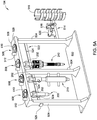
- Figure 5A is a schematic perspective view of the tool storage unit 104 according to one embodiment of the present disclosure.
- the tool storage unit 104 is capable of identifying tools, such as the drilling tools 200, 300, 400, the casing tools 240, 340, 440, and the cementing tools 270, 370, 470 described above.
- the tool storage unit 104 may include a base 502, a beam 506, two or more (three shown) columns 504 connecting the base to the beam 506, such as by welding or fastening, and one or more parking spots 508 for tools, such as the drilling tools 200, 300, 400, casing tools 240, 340, 440, and cementing tools 270, 370, 470.
- tools such as the drilling tools 200, 300, 400, casing tools 240, 340, 440, and cementing tools 270, 370, 470.
- Four parking spots 508 are shown in Figure 5A .
- the tool storage unit 104 may include any suitable number of parking spots 508 according to needs. Tools, the drilling tool 200, the casing tool 240, and the cementing tools 270, may be hung from the beam 506 by engagement of the parking spots 508 with respective couplings 204 of the tools.
- Each parking spot 508 may include an opening formed through the beam 506, a ring gear 510, and a motor 512.
- Each ring gear 510 may be supported from and transversely connected to the beam 506 by a bearing (not shown) such that the ring gear 510 may rotate relative to the beam 506.
- Each bearing may be capable supporting the weight of any of the tools and placement of a particular tool in a particular parking spot 508 may be arbitrary.
- Each ring gear 510 may have an internal latch profile, such as a bayonet profile, to latch with the bayonet profile in the coupling 204, 242, 272 of each tool.
- the tool storage unit 104 may further include a side bar 514 for holding one or more accessories, such as a cargo hook 516 and a pipe clamp 518.
- the side bar 514 may also hold a tool holder 520 used by the tool change unit 106.
- the tool storage unit 104 may include a tool identifying unit 522.
- the tool identifying unit 522 may include a plurality of readers 524 disposed on a frame 526. Each of the plurality of readers 524 may be positioned to read identification devices on tools disposed on a corresponding parking spot 508.
- each reader 524 may include a RFID reader having two-way radio transmitter-receiver for reading RFIDs. When a tool is disposed on a corresponding parking spot 508, the reader 524 may send a signal to the RFID devices on the tool and read responses from the RFID devices.
- the reader 524 may be a barcode reader, such as a linear barcode reader or a matrix barcode reader, configured to read barcodes on an identification tag of a tool.
- the reader 524 may be a camera positioned at a direct line of sight with an identification label on a tool loaded in the corresponding parking spot 508. The camera may capture an image of a portion of the tool with an identification tag.
- the reader 524 may include an optical sensor configured to detect presence or non-presence of a tool in the corresponding parking spot 508. The optical sensor may be used to trigger the reader 524 to initiate an identifying process.
- the tool storage unit 104 may include one or more connection pads 528.
- the one or more connection pads 528 may be connected to a power source to supply electrical power to active identification devices on tools disposed in the parking spot 508.
- the one or more connection pads 528 may be connected to an input/output interface of a controller to exchange signals with identification devices in tools disposed in the parking spot 508.
- one or more connection pads 528 may be formed on the ring gear 510 in each parking spot 508. When a tool is stored in a parking spot 508, the one or more connection pads 528 are in contact with the tool.
- the ring gear 510 may rotate so that the one or more connection pads 528 connect with a conductive pad, such as conductive pads 406 in the drilling tool 400, the casing tool 440, or the cementing tool 470.
- the plurality of readers 524 may be connected to a control system, such as the central control unit 108, by wired or wireless communication. By receiving information from the plurality of readers 524, the control system knows which tool is in which location.
- the tool storage unit 104 may perform tool identification routinely or automatically triggered by certain events, such as tool loading, tool unloading, or when an external tool handler, such as the tool change unit 106, needs to pick up a particular tool. For example, when a tool is loaded to a parking spot 508, the corresponding reader 524 retrieves identify information of the tool and sends the tool identification to a controller to update the inventory of the tool storage unit 104.
- the reader 524 includes a RFID reader
- the RFID reader may transmit query signals and detect response signal from the RFID on the tool. The RFID reader interprets the response signal to abstract information of the tool, such as identity information. The RFID reader may then send the identification information to the control system.
- the reader 524 includes a barcode reader, such as a linear barcode reader or a matrix barcode reader
- the reader 524 detects and reads the barcode, and sends the barcode to the control system.
- the reader 524 includes a camera
- the camera captures an image of an identification tag, and sends the image to a computer where texts and/or barcode in the image can be recognized.
- FIG. 5B is a schematic perspective view of a tool storage unit 104' according to another embodiment of the present disclosure.
- the tool storage unit 104' is similar to the tool storage unit 104 except that the tool storage unit 104' includes a carousel 530 for supporting tools.
- the carousel 530 may include a lower turntable 532, an upper disk 534, and a shaft 536 connecting the lower turntable 532 and the upper disk 534.
- the lower turntable 532 may be driven by a motor (not shown).
- a plurality of parking spots 540 may be formed at an outer perimeter of the upper disk 534 for receiving tools. Particularly, each parking spot 540 may include a notch for receiving support tools 200, 240, 270 at the respective couplings 204, 242, 272.
- the carousel 530 may allow maintenance/initial loading on one side while deployment of a tool on another side.
- the lower turntable 532 may be a fixed base and the upper disk 534 may be a turntable instead
- the tool storage unit 104' includes one or more readers 524 positioned to identify tools disposed in the plurality of parking spots 540.
- a plurality of readers 524 may be attached to the shaft 536, each reader 524 corresponds to a parking spot 540.
- the tool storage unit 104' may include one reader 524 fixedly positioned adjacent to an identifying position. The rotation of the upper disk 534 allows the tools in every parking spot 540 to align with the reader 524 during identification.
- the tool storage unit 104' may include one or more connection pads 528 at each parking spot 540 where a tool contacts the parking spot 540.
- the one or more connection pads 528 may be connected to a power source to supply electrical power to active identification devices or connected to an input/output interface of a controller to exchange signals with identification devices.
- the active identification devices may be powered by wireless power transfer.
- the active identification devices may include an internal power source, such as a power generator or a battery unit.
- tool identification may be performed by the tool change unit 106.
- the tool change unit 106 may perform tool identification while picking up a tool from the tool storage unit 104 before rig up. Exemplary tool change units capable of identifying tools are described below.
- Figure 6A is a schematic perspective partial view of the tool change unit 106 having a reader 602 according to one embodiment of the present disclosure.
- the reader 602 may be capable of reading RFIDs, barcodes, such as linear barcodes and matrix barcodes, and/or capturing images of texts on identity tags for recognition.
- the reader 602 may include an RFID reader.
- the reader 602 may include a barcode reader, such as a linear barcode reader or a matrix barcode reader.
- the reader 602 may include a camera.
- the reader 602 may be connected to a controller, such as the central control unit 108, where the identification of the tool may be processed.
- the reader 602 may be attached to the tool holder 174 of the tool change unit 106.
- Figure 6B is a partial enlarged view of the tool holder 174 where the reader 602 is attached to an upper surface of the tool holder 174.
- the reader 602 is within a range to read an RFID on the tool or in a directly line of sight of an identification tag on the tool.
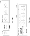
- Figure 6C is a partial perspective view of a tool change unit 106' according to one embodiment of the present disclosure.
- the tool change unit 106' is similar to the tool change unit 106 except that the tool change unit 106' includes a reader 606 attached to the forearm 170 by a bracket 604.
- Figure 6D is a partial sectional view of a tool change unit 106" according to another embodiment of the present disclosure.
- the tool change unit 106" includes one or more connection pads 608 formed on the tool holder 174.
- the one or more connection pads 608 may be connected to a power source to supply electrical power to active identification devices or connected to an input/output interface of a controller to exchange signals with identification devices.
- the one or more connection pads 608 may be positioned to establish physical contact with a tool with active identification devices, such as the drilling tool 400.
- signal and/or power communication with the identification devices may be established by wireless communication.
- the one or more connection pads 608 may contact the conductive pad 406 of the drilling tool to power up or establish wired connection with the active identification device 402.
- the modular top drive system 100 may use the tool change unit 106, 106' or 106" to identify a tool during rig-up.
- the central control unit 108 may command the tool change unit 106, 106', 106" to move towards the tool storage unit 104 to identify and pick up the correct tool.
- the tool change unit 106 may move the reader 602, 604 close to a tool in the tool storage unit 104 to retrieve identification information of the tool.
- the identification device in the tool is a passive device, such as an RFID, linear barcodes, matrix barcodes, or texts
- the reader 602 may read the identification device before gripping the tool.
- the reader 602 may send the identification information to the central control unit 108. If the central control unit 108 confirms the tool to be the correct one, the tool change unit 106, 106', 106" moves forward to grip the tool from the tool storage unit 104 and transfer the tool to the top drive unit 102 for installation.
- the tool change unit 106, 106', 106" moves to the next tool in the tool storage unit 104 until the correct tool is located.
- the identification may be performed in the tool change unit 106, 106', 106" directly, and the tool change unit 106, 106', 106" will pick up the tool once the correct tool is identified.
- the tool change unit 106' moves to grip the tool to power up the active identification device.
- the active identification device may be powered with the tool storage unit 104. Once powered up, the active identification device can transfer the identification information to the tool change unit 106".
- the tool change unit 106" transfers the tool to the top drive unit 102. If the tool is not the correct tool, the tool change unit 106" returns the tool back to the tool storage unit 104 and moves to the next tool.
- tool identification may be performed in the top drive unit 102.
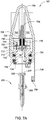
- Figure 7A is a schematic sectional view of the top drive unit 102 capable of identifying tools according to one embodiment of the present disclosure.
- the top drive unit 102 may be a motor unit having one or more drive motors 702.
- Stator of the one or more drive motors 702 may be connected to a drive body and rotors of the one or more drive motors 702 may be torsionally connected to a drive ring 712.
- the drive ring 712 may have a latch profile for selectively connecting one of: a drilling tool, a casing tool, a cementing tool, a completion tool, a fracturing tool, a pump, a sand screen, a clamping tool, an internal gripping tool, an external gripping tool, an adaptor, and a combination thereof to the motor unit.
- the top drive unit 102 may also include a becket 704, a hose nipple 706, a mud swivel 708, a thread compensator 714, a swivel 716, a down thrust bearing 718, an up thrust bearing 720, a swivel frame 722, a bearing retainer 724.
- the drive body 710 may be connected to the rail 124 by a trolley.
- a trolley may be fastened to a back of the drive body 710.
- the trolley may be transversely connected to a front of the rail 124 and may ride along the rail, thereby torsionally restraining the drive body 710 while allowing vertical movement of the top drive unit 102.
- the drive body 710 may be rectangular and have thrust chambers formed therein. In one embodiment, the drive body 710 may have an inner rib dividing the thrust chambers. The drive body 710 may have a central opening formed therethrough and in communication with the chambers.
- the drive ring 712 may be movable disposed in the drive body 710.
- the thrust bearings 718, 720 are disposed between the drive ring 712 and the drive body 710 allowing the drive ring 712 to rotate relative to the drive body 710.
- the drive ring 712 may have an inner locking profile 726 formed at an upper end thereof and an inner latching profile 728 formed adjacently below the inner locking profile 726.
- the inner latching profile 728 may be a bayonet profile matching the external profile 210 of the coupling 204 in the tools discussed above.
- Each thrust bearing 718, 720 may include a shaft washer, a housing washer, a cage, and a plurality of rollers extending through respective openings formed in the cage.
- the shaft washer of the down thrust bearing 718 may be connected to the drive ring 712 adjacent to a bottom of the flange thereof.
- the housing washer of the down thrust bearing 718 may be connected to the drive body 710 adjacent to a top of the rib thereof.
- the cage and rollers of the down thrust bearing 718 may be trapped between the washers thereof, thereby supporting rotation of the drive ring 712 relative to the drive body 710.
- the down thrust bearing 718 may be capable of sustaining weight of either a drill string or a casing string during rotation thereof.
- the shaft washer of the up thrust bearing 720 may be connected to the drive ring 712 adjacent to the bearing retainer 724.
- the housing washer of the up thrust bearing 720 may be connected to the drive body 710 adjacent to a bottom of the rib thereof.
- the cage and rollers of the up thrust bearing 720 may be trapped between the washers thereof.
- the bearing retainer 724 may have an inner thread engaged with the outer thread of the drive ring 712, thereby connecting the down thrust bearing 718 to the drive ring 712.
- the drive motors 702 may be electric (shown) or hydraulic (not shown) and have a rotor and a stator.
- the motors 702 may be operable to rotate the rotor relative to the stator which may also torsionally drive the drive ring 712 via gears.
- the top drive unit 102 may instead be a direct drive unit having the drive motor 702 centrally located.
- the hose nipple 706 may be connected to the mud swivel 708 and receive an end of a mud hose to deliver drilling fluid.
- the mud swivel 708 may be connected to a top of the swivel frame 722, such as by fastening.
- the swivel frame 722 may be connected to a top of the drive body 710, such as by fastening.
- the hydraulic swivel 716 is configured to provide hydraulic connections to the tools attached to the top drive unit 102.
- the hydraulic swivel 716 may include a non-rotating inner barrel and a rotating outer barrel.
- the inner barrel may be connected to the swivel frame 722 and the outer barrel may be supported from the inner barrel by one or more bearings.
- the outer barrel may have hydraulic ports (six shown) formed through a wall thereof, each port in fluid communication with a respective hydraulic passage formed through the inner barrel (only two passages shown).
- the top drive unit 102 may include a universal coupler to lock a tool to the drive ring 712 and/or to provide electrical and/or hydraulic connections to the tool.
- the thread compensator 714 may include a linear actuator 730, a locking ring 732, and one or more (such as three, but only one shown) locking pins 734.
- the locking ring 732 may include a locking head 733 extending into the locking profile 726 of the drive ring 712.
- the linear actuator 730 may move the locking ring 732 vertically so that the locking head 733 moves vertically in the drive ring 712.
- the locking head 733 may have a profile that allows the locking head 733 mate with the external prongs 210p of the coupling 204 of the tools discussed above.
- the locking pins 734 may be pistons.
- the locking pins 734 may align with the locking slots 207 of the coupling 204 and extend therein to secure the locking ring 732 to the coupling 204.
- the top drive unit 102 may include an identification reader 738 configured to read identification tools approaching the top drive unit 102.
- the identification reader 738 may be attached to the drive body 710 by a bracket 736.
- two or more identification readers 738 may be mounted at various locations to make sure at least one identification reader 738 has a direct line of sight or is within the range of the identification devices of the tool.
- the one or more identification reader 738 may be disposed on the top drive unit 102 along the path of a tool while the tool is being installed. For example, one or more identification reader 738 may be disposed on the drive ring 712 and/or the locking ring 732.
- the at least one identification reader 738 may be disposed on a location to read the identification devices on a tool when the tool is installed on the top drive unit 102.
- the bracket 736 may be movable relative to the drive body 710 to align with identification devices on the tool.
- one or more identification readers 738 may be mounted on a rotating part of the top drive unit 102, such as on the drive ring 712. The top drive unit 102 may rotate the drive ring 712 with one or more identification readers 738 attached thereon to align the one or more identification readers 738 with the identification devices on the tool.
- the identification reader 738 may query identification devices on a tool when the tool is raised towards the top drive unit 102, for example, by the tool change unit 106.
- the identification reader 738 may be similar to the readers 524, 602 described above.
- the identification reader 738 may be a RFID reader, a barcode reader, or a camera.
- the identification reader 738 on the top drive unit 102 may be used to check the identification of the tool to make sure the correct tool is being rigged up.
- a tool handler such as the tool change unit 106 may raise a tool, such as the drilling tool 200, until the tool is adjacent the reader 738 below the bottom of the drive ring 712 so that the reader 738 can read the identification devices on the tool.
- the reader 738 may determine locally or send to the central control unit 108 to determine if the tool is the correct one. If the tool is not correct, the central control unit 108 may command the tool handler to retrieve another tool until the correct tool is identified.
- the drive motors 702 may then be operated to rotate the drive ring 712 until the latching profile 728 of the drive ring 712 aligns with the external prongs of the head 208.
- the drive ring 712 may have visible alignment features, such as cameras, for alignment.
- the tool change unit 106 may be raised to lift the coupling 204 of the drilling tool 200 into the drive ring 712 until the head 208 passes the latching profile 728 and enters the locking profile 726 thereof.
- the locking ring 732 may be in a lower position, such as the hoisting position, such that the top of the head 208 contacts the locking ring 732 and pushes the lock ring upward.
- Proximity sensor may be used to determine alignment of the head 208 with the locking profile 726 by measuring the vertical displacement of the locking ring 732.
- the compensator actuator 730 may be operated to move the locking ring 732 to the ready position.
- the drive motors 702 may then be operated to rotate the drive ring 712 until sides of the external prongs of the head 208 engage respective stop lugs of the locking profile 726, thereby aligning the external prongs of the head 208.
- the compensator actuator 730 may then be operated to move the locking ring 732 to the hoisting position, thereby moving the locking head 733 into the external prong-ways of the head 208 and aligning the locking pins 734 with the respective locking slots 207. Movement of the locking ring 732 may also make hydraulic junction between the drilling tool 200 and the top drive unit 102.
- the drilling tool 200 is now longitudinally and torsionally connected to the drive ring 712.
- FIG. 7B is a schematic sectional view of a top drive unit 102' according to one embodiment of the present disclosure.
- the top drive unit 102' is similar to the top drive unit 102 except that the top drive unit 102' includes one or more connection pads 740 configured to provide electrical power and/or wired connection to identification devices, such as active identification devices, in tools.
- Each connection pad 740 may be coupled to a connection 742.
- the connection 742 may be coupled to a power source or an input/output interface of a controller, such as the central control unit 108.
- the one or more connection pads 740 may be formed on a surface of the drive ring 712 that contacts the tool during operation and/or alignment.
- connection pads 740 may be formed on the inner locking profile 726 to make connection of conductive pads 406 on the head 208 of the coupling 204.
- the one or more connection pads 740 may be coupled to any suitable locations.
- wireless power transfer may be used to provide electrical power to the tool.
- Figure 7C is a schematic section view of the top drive unit 102' in position of identifying the drilling tool 400.
- the coupling 204 of the drilling tool 400 is inserted into the drive ring 712 so that the one or more connection pads 740 are electrically connected to the one or more conductive pads 406 of the drilling tool 400.
- the active identification device 402 of the drilling tool 400 is therefore connected and the identification of the drilling tool 400 is obtained. If the drilling tool 400 is the correct tool, the drive ring 712 will rotate to lock the drilling tool 400 in and complete the rigging up procedure. If the drilling tool 400 is not the correct tool, a tool handler, such as the tool change unit 106, will lower the drilling tool 400 out of the drive ring 712 and fetch an alternative tool.
- identification devices on tools may be used to store operational information in addition to identification information.
- the identification devices may be used to store running time of a tool, running time of a tool used on a particular top drive, and operational range of a tool, such as torque, pressure, and tonnage.
- the running time may be used to monitor the life time of the tool.
- the running time of a tool used on a particular top drive may be used to assist tool rental.
- the additional information may be updated by re-writing identification devices on a tool. The re-writing may be performed by a writer when the tool interacts with the tool storage unit, the tool change unit, or the top drive unit.
- the writer may be a RFID writer attached to tool storage unit, tool change unit or tool drive unit.
- the writer may be a micro-controller in an active identification device upon receiving commends from a central unit controller.
- tool information may be updated by replacing the existing tool identification device with a new identification device.
- the tool identification device includes barcode tags, or text tags
- updated tool information may be incorporated in new tags, which may replace with the existing tags.
- the tags may be replaced manually.
- the top drive unit, the tool change unit or the tool storage unit may include one or more identification devices, such as RFIDs, barcode tags, and/or text tags.
- the identification devices may be read by various identification readers and used to provide location of the identification reader or the location of the top drive unit, the tool change unit or the tool storage unit.
- one or more tool may include an identification reader configured to read identification devices disposed on the top drive unit, the tool change unit or the tool storage unit.
- the identification reader on the tool may be used to provide location of the tool by reading identification devices on location markers, such as the top drive unit, the tool change unit, the tool storage unit.
- the identification reader may be used to read identification devices disposed on other components of the system, such as the top drive unit, the tool change unit, the tool storage unit, or other tools.
- the identification reader tool may be powered by an internal power supply, such as batteries, a power generator, or by an external power supply.
- the identification reader on the tool may be powered by an external power supply through the drive unit, the tool change unit or the tool storage unit by wired connection or wireless connection.
- the tool may include a battery or a power generation configured to provide power supply to the identification reader.
- a trigger to read may be generated when power is provided to the identification reader from that the drive unit, the tool change unit or the tool storage unit or, if the identification reader is already powered, when the identification reader receives a command, for example a command from the central control unit.
- the identification reader on the tool reads the identification devices, the identification device on the tool change unit, the top drive unit, or the tool storage unit, and transfers to the central control system the identification of the tool itself along with the identification information of the identification device being read.
- the central control unit may correlate the identification information of the tool and the identification device being read and determine a location of the tool.
- each parking spot of the tool storage unit may have different ID, so the identification reader on the tool can read the ID in each parking spot in the storage unit and transfer IDs of its own and the parking spot to let the system know the position of the tool.
- Embodiments of the present disclosure also include a modular central control system adapted to control various tools or parts that may be selectively connected the modular top drive system described above.
- the modular central control system may include a central control unit configured to communicate with and control various tools, including modular tools or parts that selectively connect to the system or permanent tools in the system.
- a tool or part that can be connected to the modular top drive system may have an independent controller.
- the tool or part may have a modular controller.
- the corresponding modular controller may be added to or activated in a central controller, such as the central control unit 108 of Figure 1 .
- an identification of the tool or part can be sent to the central control unit so that a corresponding program can be loaded and activated in the central control unit.
- the modular central control system can be updated simply by adding a new modular program corresponding to the new part.
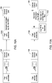
- FIG 8 is a schematic connection diagram of a modular central control system 800 according to one embodiment of the present disclosure.
- the modular central control system 800 may include the central control unit 108 connected to various tools and parts. As described in Figure 1 , the central control unit 108 may be connected to the top drive unit 102, the tool storage unit 104, and the tool change unit 106 to facilitate automatic tool identification and automatic tool exchange.
- the central control unit 108 may be one or more computers or one or more programmable logic controllers.
- the central control unit 108 may be connected to a driller chair 802, where a drilling operator can input operational commands.
- the driller chair 802 may include various input devices, such as a control panel having one or more control buttons, a keyboard, a joystick, or a microphone.
- the central control unit 108 may also connected to a display unit 804, such as a monitor screen.
- the display unit 804 may be used to provide visualization for the drilling operator to make control decisions.
- the modular central control system 800 may include a JAM (Joint Analysis and Makeup) server 812, and one or more JAM clients 806, 812 connected to the central control unit 108.
- the JAM server 812 and JAM clients 806, 812 may be used to provide rotation and torque control during operation.
- the JAM server 812 may be a stand-alone computer connected to the central control unit 108.
- the JAM server 812 may include a storage unit for storing data for operations, such as data for each makeup or break out.
- the JAM server 812 may be a storage unit in the central control unit 108.
- the JAM client 806 may be a terminal computer disposed near the driller chair 802 to allow the drilling operator to operate at the driller chair 802.
- the JAM client 814 may be a mobile unit, such as a tablet, that allows JAM operations at flexible locations.
- the central control unit 108 may be connected to a mobile unit 808.
- the mobile unit 808 allows the operator to operate and control the system away from the driller chair 802.
- the central control unit 108 may be connected to a router 816.
- the router 816 allows components of the modular control system 800 to connect with the Internet.
- the router 816 also enables remote support to all components of the modular control system 800 from locations away from the modular control system 800.
- the central control unit 108 may be connected to an anti-collision unit 810 configured to prevent any collision among different tools and parts.
- the anti-collision unit 810 may be a stand-alone controller, such as a stand-alone computer.
- the anti-collision unit 810 may be integrated in the central control unit 108.
- the central control unit 108 may be connected to a power tong positioning and controlling unit 818 to interact with power tongs 840, a stab master 842, a positioning device 844on the rig.
- the power tong positioning and controlling unit 818 may be the HiPer Control System by Weatherford, Inc.
- the power tong positioning and controlling unit 816 may be connected to the power tongs 840, the stab master 842, and the positioning device 844 by wire.
- the power tong and controlling unit 818 may be controlled wirelessly.
- the power tongs 840, the stab master 842, and the positioning device 844 may be controlled directly by the central control unit 108 without the power tong positioning and control unit 818.
- the central control unit 108 may also be connected to an iron roughneck unit 817 having with an onboard controller.
- the central control unit 108 may be connected to the top drive unit 102, the tool storage unit 104, and the tool change unit 106.
- the central control unit 108 may communicate with the built-in controller.
- the central control unit 108 may be connected to a VFD (variable frequency drive) controller 820.
- VFD variable frequency drive
- the VFD controller 820 may be used to control the top drive unit 102.
- the central control unit 108 may be connected to other devices on a drilling rig, such as a power generation unit 822, a drawworks unit 824, a drilling fluid pump 826, and a vision unit 828.
- the central control unit 108 is also connected to one or more modular tools 830.
- the modular tools 830 may include tools configured to selectively connect to the top drive unit 102, such as the drilling tool 200, the casing tool 240, and the cementing tool 270.
- a combined multi-coupler (CMC) 834 may be connected to the top drive unit 102.
- the combined multi-coupler 834 may be used to connect the modular tools 830 to the central control unit 108 and/or the top drive unit 102.
- the combined multi-coupler 834 may connect directly to the top drive unit 102.
- the combined multi-coupler 834 may connect with the modular tools 830 when the modular tools 830 are directly coupled to the combined multi-coupler 834.
- the combined multi-coupler 834 may connect with other units by wireless communication.
- the combined multi-coupler 834 is configured to make multiple connections, such as connections for axial and/or torsional loads, bore fluid, pressure fluid, electric power, and analytic and/or digital data.
- the combined multi-coupler 834 may include a load transfer feature corresponding to a load transfer feature on a tool so that the combined multi-coupler 834 may transfer axial and/or torque loads to the tool connected.
- the combined multi-coupler 834 may also include a seal profile to seal with a tool to transfer bore fluid to and from the tool.
- the combined multi-coupler 834 may further include one or more couplers for transfer pressured fluid, electric power, data, or other signals.
- identification information of the tool may be sent to the central control unit 108 through the combined multi-coupler 834.
- the tool identification information may be transfer through a data coupler, an electric power coupler, or other suitable connections in the combined multi-coupler 834 to the central control unit 108.
- the central control unit 108 may also connect to a plurality of rig tools 832, such as bails, tongs, spiders, wellheads, pipe tracking units, remote controls, and the like.
- rig tools 832 such as bails, tongs, spiders, wellheads, pipe tracking units, remote controls, and the like.
- the central control unit 108 may communicate with various tools and units by wired communication or wireless communication.
- FIG. 9 is a schematic software diagram showing connection of the central control unit 108 according to one embodiment of the present disclosure.
- the central control unit 108 may include computer software installed on a storage media, such as a hard drive.
- the computer software may be run by a controller of the central control unit 108 to perform desired control and processing tasks.
- the central control unit 108 may have an add-on tool group 910 including software modules configured to communicate with and/or control add-on tools, such as modular tools 830.
- the add-on tool group 910 may include a drill tool module 912 configured to communicate with and/or control a drill tool, such as the drill tool 200.
- the add-on tool group 910 may include a cementing tool module 914 configured to communicate with and/or control a cementing tool, such as the cementing tool 270.
- the add-on tool group 910 may also include a casing tool module 916 configured to communicate with and/or control a casing tool, such as the casing tool 240.
- the software modules in the add-on tool group 910 may be selectively loaded when a corresponding tool is connected to the system.
- a drill tool module 912 may be loaded when the drill tool 200 is attached to the top drive unit 102.
- the software modules in the add-on tool group 910 may be downloaded from a remote location, for example, through Internet, and then activated when the corresponding modular tools are connected to the system.
- a software module for a modular tool may be pre-installed in the add-on tool group 910 and only activated when the modular tool is connected to the system. When a modular tool is disconnected from the system, the corresponding software module may be removed or deactivated from the add-on tool group 910.
- the central control unit 108 may have a standard tool module group 920 including software modules configured to control tools that are standard or permanent to a system, such as a drilling rig.
- the standard tool module group 920 may include a coupler module 921, a spider module 922, a tong module 923, a drive unit module 924, a tool changer module 925, a tool storage module 926, or any modules for similar tools.
- the software modules in the standard tool module group 920 may remain active during operation.
- the central control unit 108 may have a safety module group 930 including software modules configured to monitor and maintain the safety during operation.
- the safety module group 930 may include an interlocks module 932, a safety module 934, an anti-collision module 936, or any software module configured to perform safety functions.
- the software module in the safety module group 930 may coordinate among two or more tools in the system to ensure safety and prevent interference among different tools.
- the central control unit 108 may have an operation module group 940 including software modules configured to automatically perform a particular operation with different tools.
- the operation module group 940 may include an automatic tool change module 941, an automatic drilling module 942, an automatic cementing module 943, an automatic casing module 944, or any operations that the system is configured to run.
- the software module in the operation module group 940 may be selectively loaded or activated when a particular operation is scheduled to run.
- the automatic drilling module 942 is loaded or activated when the system is to perform a drilling operation.
- the software modules in the operation module group 940 may be customized or exchanged according to the particular operation requirements.
- the central control unit 108 may run one or more software modules to communicate and/or control various tools and parts in the system through the connections between the central control unit 108 and the tools and parts.
- the connections may be wired connection, wireless connection, or combinations thereof.
- the connections may be direct connection or indirect connections.
- the central control unit 108 may communicate with the operator by sending information of the tools and parts, such as, the information from the modular tools, standard tools, the sensors, or the like, in the system to the display unit 804 where the information can be visualized for the operator to observe.
- the central control unit 108 also receives operator inputs from the driller chair 802, the laptop 808, or other input devices, and plugs the operator inputs to the software modules to implement the operator's commands.
- the central control unit 108 may communicate with the JAM server 812 or the JAM client 814 to monitor and control the rotation and torque during operation. For example, the central control unit 108 receives pipe data from JAM client 814, processes the received data through the relevant software module(s), and sends torque, turn, and time to the JAM server 812 or JAM client.
- the tool 830 may send various information, such as standard tool information, special tool information, feedback from sensors or software on the tool, to the central control unit 108, where the information may be processed using the relevant software modules, and tool commands are sent back to the tool 830 to implement tool control.
- information such as standard tool information, special tool information, feedback from sensors or software on the tool
- the central control unit 108 receives information of the standard tool and any feedback from the sensors or onboard software, processes the information through relevant software module, such as the tong module 923 for the tong, and sends commands to the tool.
- relevant software module such as the tong module 923 for the tong
- the central control unit 108 may not require information of the tool.
- the central control unit 108 may only require feedback from the software or sensor on the tool change unit 106.
- Figures 10A is a schematic diagram of communication between an active tool 1010 and the central control unit 108 when the active tool 1010 is connected to the central control unit 108.
- the active tool 1010 may be a tool or part having a controller, such as a microcontroller.
- the controller in the active tool may run a control program for controlling the active tool 1010.
- the active tool may also include a storage medium where the control program and tool information are stored.
- the controller in the active tool 1010 will send the identification information to the central control unit 108.
- the active tool 1010 may be identified by an identification tag, such as an RFID tag.
- a software module corresponding to the active tool 1010 may be loaded or activated in the central control tool 108.
- the central control unit 108 can then either read standard information stored in the active tool 1010 or the active tool 1010 can send the standard information to the central control unit 108.
- the standard tool information may include the identification number of the tool, the operation parameters of the active tool 1010, such as the maximum allowed RPM, the maximum torque, and dimension of the active tool 1010.
- a software module in the central control unit 108 for an active tool mainly includes commands to the active tool and processes software and/or sensor feedback from the active tool.
- the controller in the active tool 1010 handles the hardware interaction. From the point of view of the central control unit 108, the active tool 1010 is a black box. Communication between the active tool 1010 and the central control unit 108 is implemented by a predefined software interface.
- Figures 10B is a schematic diagram of communication between the active tool 1010 and the central control unit 108 during operation.
- the central control unit 108 sends commands to the active tool 1010.
- the controller in the active tool 1010 will function to check the received commands according to the hardware of the active tool, perform any calculations if necessary, and output the commands to the hardware of the active tool 1010 accordingly.
- the controller of the active tool 1010 may then send feedback to the central control unit 108 through the software interface.
- FIGS 11A-11B are schematic diagrams of communication between a passive tool 1100 and the central control unit 108.
- the passive tool 1100 does not have a controller.
- bails are typically a passive tool.
- the passive tool 1100 may include an identification device, such as a RFID.
- the passive tool 1100 when the passive tool 1100 is connected to the system, the passive tool 1100 may be identified by the identification device and the identification information of the passive tool 1100 stored in the identification device may be sent to the central control unit 108. Alternatively, the identification information of the passive tool 1100 may be entered to the central control unit 108 by the operator. Standard information of the passive tool may be retrieved from a database 1102 of configuration files. The database 1102 may be stored in the central control unit 108 or stored in a remote location.
- FIG. 11B is a schematic diagram of controlling the passive tool 1100.
- a software module 1110 may be used to control the hardware of the passive tool 1100.
- the software module 1110 may receive commands, for example from other software modules in the central control unit 108.
- the software module 1110 may check the received command, do calculation of necessary, and output the hardware command accordingly.
- the software module 1110 may send feedback to the corresponding software modules in the central control unit 108.
- FIG 12A is a schematic diagram of an antic-collision procedure wherein the central control unit 108 communicates with the tool 830, the driller chair 802, and the drawworks unit 824.
- the anti-collision module 936 in the central control unit 108 may be invoked to prevent collision among the parts, for example the collision between the bottom and the tool 830 connected to the top drive unit 102.
- the anti-collision module 936 may calculate the position of the top drive unit 102 connected with the tool using the position given by the drawworks unit 824 and the dimension of the tool.
- the anti-collusion module 936 may obtain information of tool height from the tool 830.
- the operator may enter upper and lower limits through the driller chair 802.
- the drawworks unit 824 may send height information to the central control unit 108 and the anti-collision module 936.
- the anti-collision module 936 may calculate combined the height of the tool and the top drive unit 102 and check if the combined height is between the lower and the upper limits. If the combined height is within the limits, the anti-collision module 936 will send a non-collision signal to the drawworks unit 824 to give the drawworks unit 824 the permission to move the top drive unit 102.
- Figure 12B is a schematic diagram of a torque control procedure performed in the central control unit 108.
- limits of RPM and/or limits of torque may be sent to the central control unit 108 by the operator through the driller chair 802, the JAM client 814, and/or by the tool 830.
- the power tong positioning and controlling unit 818 and/or the top drive unit 102 may send the current RPM and/or current torque to the central control unit 108.
- the central control unit 108 checks if the current RPM and/or current torque is within the limits. If the current RPM and/or current torque exceed the limits, the central control unit 108 sends a stop/dump command to the power tong positioning and controlling unit 818 and/or the top drive unit 102.
- Embodiment of the present disclosure includes a tool for construction of a wellbore.
- the tool includes a coupling for connecting to a top drive unit by a friction structure or by a load bearing head, and one or more identification devices including identification information.
- the coupling may include a head having a latching profile to selectively connect the tool to the top drive unit.
- the coupling may further include a lifting shoulder allowing a tool changer to lift the tool, and a neck extending between the head and the lifting shoulder.
- the one or more identification devices may be one of a radio frequency identification device (RFID), a bar code tag, and a text tag.
- RFID radio frequency identification device
- the tool may include two or more identification devices disposed at intervals on an outer surface of the lifting shoulder.
- the one or more identification devices may be active identification device powered by an external power supply, hydraulically generated power, or battery.
- the tool may further include one or more conductive pads connected to the one or more identification devices.
- the one or more conductive pads are configured to connect the one or more identification devices to a power supply and/or an input/output interface of a controller.
- the one or more identification devices may be powered by the external power supply through a wireless connection.
- the tool may be a drilling tool, a casing tool, a cementing tool, a completion tool, a fracturing tool, a pump, a sand screen, a clamping tool, an internal gripping tool, an external gripping tool, an adaptor, or a combination thereof.
- the one or more identification devices may include a micro-controller, and a memory unit programmable to store identity information, and/or operational information.
- the one or more identification devices may further include an interface to communicate with a central control unit.
- the memory unit is re-writeable.
- Embodiment of the present disclosure may include a top drive unit for construction of a wellbore.
- the top drive includes a drive body, a drive motor having a stator connected to the drive body, a coupler torsionally connected to a rotor of the drive motor for selectively connecting a tool, and an identification reader configured to obtain identity information from an identification device on the tool.
- the coupler may have a latch profile for selectively connection with the tool.
- the coupler may be coupled to the tool by a friction structure or by a load bearing head.
- the identification reader may be one of a radio frequency identification device reader, a barcode reader, and a camera.
- the identification reader may be powered by at least one of an external power supply, hydraulically generated power, and battery.
- the identification reader may include one or more connection pads configured to connect an identification device on the tool to a power supply and/or an input/output interface of a system controller.
- the identification reader may be powered by an external power supply using a wireless connection.
- the identification reader may be connected to a central control unit.
- the tool change unit includes a tool holder configured to lift a tool, a drive assembly configured to move the tool holder, and an identification reader configured to obtain identity information from an identification device on the tool.
- the drive assembly may include a base mountable to a subfloor structure of a drilling rig, a post extending from the base to a height above a floor of the drilling rig, a slide hinge transversely connected to the post, and an arm connected to the slide hinge, wherein the tool holder is attached to the arm.
- the identification reader may be attached to the tool holder.
- the identification reader may be one of a radio frequency identification device reader, a barcode reader, and a camera.
- the identification reader may be powered by an external power supply, hydraulically generated power, or battery.
- the identification reader may include one or more connection pads configured to connect an identification device on the tool to a power supply and/or an input/output interface of a system controller.
- the identification reader may be powered by an external power supply by a wireless connection.
- the tool storage unit includes a frame having one or more parking spots, wherein each parking spot is configured to receive one of a drilling tool, a casing tool, a cementing tool, a fracturing tool, a pump, a sand screen, a clamping tool, an internal gripping tool, an external gripping tool, an adaptor, or a combination thereof, and an identification reader configured to obtain identity information from identification devices on tools in the parking spots.
- the identification reader may be one of a radio frequency identification device reader, a barcode reader, and a camera.
- the identification reader may be powered by an external power supply, hydraulically generated power, or battery.
- the identification reader may include one or more connection pads configured to connect an identification device on the tool to a power supply and/or an input/output interface of a system controller.
- the identification reader may be powered by an external power supply by a wireless connection.
- the tool storage unit may further include a rack.
- the rack may include a base, a beam, and two or more columns connecting the beam and the base, wherein the one or more parking spots are formed on the beam.
- the rack may include a disk, wherein the one or more parking spots are formed on the disk, a turntable configured to rotate the disk, and a shaft supporting the disk.
- the modular top drive system includes a top drive unit for selectively connecting to a tool using a friction structure, a threaded connection, or a load bearing head, and an identification reader configured to obtain identity information from identification devices.
- the modular top drive system may further include a tool storage unit having one or more parking spots, wherein each parking spot is configured to receive and support a tool.
- the modular top drive system may further include a tool change unit configured to transfer tools between the top drive unit and the tool storage unit.
- the identification reader may be disposed on the top drive unit, a tool storage unit, or a tool change unit.
- the identification reader may be disposed on the tool and configured to read identification devices disposed on the top drive unit, the tool storage unit, or the tool change unit.
- the modular top drive system further includes a central control unit, wherein the identification reader is connected to the central control unit.
- the modular top drive unit may selectively connect to a drilling tool, a casing tool, a cementing tool, a fracturing tool, a pump, a sand screen, a clamping tool, an internal gripping tool, an external gripping tool, an adaptor, or a combination thereof.
- the modular top drive system may further include one or more tools including an identification device, wherein the one or more tools are selectively connected to the central control unit.
- the identification reader may be one of a radio frequency identification device reader, a barcode reader, and a camera.
- the identification reader may be powered by an external power supply, hydraulically generated power, or battery.
- the identification reader may include one or more connection pads configured to connect an identification device on the tool to a power supply and/or an input/output interface of a central control unit.
- the identification reader may be powered by an external power supply by a wireless connection.
- Another embodiment of the present disclosure provides a method for operating a modular top drive system.
- the method includes positioning a tool within a range of an identification reader, reading one or more identification devices on the tool using the identification reader to confirm the tool is the correct tool, and engaging the tool to a top drive unit.
- positioning the tool may include transporting the tool to slips positioned underneath the top drive unit.
- engaging the tool to the top drive unit may include moving the top drive unit down towards the slips.
- positioning the tool may include retrieving a tool from a tool storage unit, and transporting the tool to slips positioned underneath the top drive unit.
- positioning the tool may include retrieving a tool from a tool storage unit using a tool change unit, and transferring the retrieved tool towards a top drive unit using the tool change unit.
- confirming the tool may include, prior to retrieving the tool, identifying one or more tools stored in the tool storage unit using the identification reader in the tool storage unit.
- confirming the tool may include identifying the retrieved tool using the identification reader in the top drive unit when the retrieved tool is transferred adjacent the top drive unit, and if the retrieved tool is not the correct tool, returning the retrieved tool to the storage unit, and retrieving another tool.
- confirming the tool may include, prior to retrieving the tool, identifying one or more tools stored in the tool storage unit using an identification reader in an tool change unit, and retrieving the tool with the tool change unit upon confirming the identification of the tool.
- the method may further include sending information of the tool to a central control unit.
- the method may further include activating a software module corresponding to the tool in the central control unit, and sending command to the tool from the central control unit.
- confirming the tool may include sending tool identity information to a central control unit.
- confirming the tool may include one of reading a radio frequency identification device, reading a barcode, capturing an image of a text tag and recognizing the text tag, and receiving identity information from an active identification device. Confirming the tool may further include determining whether the tool is correct within the identification reader.
- the method further includes receiving operation history of the tool from an identification device on the tool.
- the method further includes updating operation history in the identification device on the tool upon engaging the tool.
- the method further includes replacing the tool with another tool.
- the tool may be one of a drilling tool, a casing tool, a cementing tool, a fracturing tool, a pump, a sand screen, a clamping tool, an internal gripping tool, an external gripping tool, an adaptor, or a combination thereof.
Landscapes
- Engineering & Computer Science (AREA)
- Mining & Mineral Resources (AREA)
- Life Sciences & Earth Sciences (AREA)
- Geology (AREA)
- Physics & Mathematics (AREA)
- Geochemistry & Mineralogy (AREA)
- General Life Sciences & Earth Sciences (AREA)
- Environmental & Geological Engineering (AREA)
- Fluid Mechanics (AREA)
- Mechanical Engineering (AREA)
- Remote Sensing (AREA)
- Electromagnetism (AREA)
- Geophysics (AREA)
- Earth Drilling (AREA)
- Packaging Of Annular Or Rod-Shaped Articles, Wearing Apparel, Cassettes, Or The Like (AREA)
- Machine Tool Sensing Apparatuses (AREA)
- Health & Medical Sciences (AREA)
- Toxicology (AREA)
- General Engineering & Computer Science (AREA)
- Operations Research (AREA)
- General Health & Medical Sciences (AREA)
- Artificial Intelligence (AREA)
- Computer Vision & Pattern Recognition (AREA)
- General Physics & Mathematics (AREA)
- Theoretical Computer Science (AREA)
Applications Claiming Priority (4)
| Application Number | Priority Date | Filing Date | Title |
|---|---|---|---|
| US201562203712P | 2015-08-11 | 2015-08-11 | |
| US15/004,687 US10626683B2 (en) | 2015-08-11 | 2016-01-22 | Tool identification |
| EP16754089.7A EP3334903B1 (de) | 2015-08-11 | 2016-08-11 | Werkzeugidentifikation |
| PCT/US2016/046458 WO2017027656A1 (en) | 2015-08-11 | 2016-08-11 | Tool identification |
Related Parent Applications (2)
| Application Number | Title | Priority Date | Filing Date |
|---|---|---|---|
| EP16754089.7A Division EP3334903B1 (de) | 2015-08-11 | 2016-08-11 | Werkzeugidentifikation |
| EP16754089.7A Division-Into EP3334903B1 (de) | 2015-08-11 | 2016-08-11 | Werkzeugidentifikation |
Publications (3)
| Publication Number | Publication Date |
|---|---|
| EP3839202A2 true EP3839202A2 (de) | 2021-06-23 |
| EP3839202A3 EP3839202A3 (de) | 2021-09-01 |
| EP3839202B1 EP3839202B1 (de) | 2024-06-05 |
Family
ID=56740523
Family Applications (2)
| Application Number | Title | Priority Date | Filing Date |
|---|---|---|---|
| EP16754089.7A Active EP3334903B1 (de) | 2015-08-11 | 2016-08-11 | Werkzeugidentifikation |
| EP21155708.7A Active EP3839202B1 (de) | 2015-08-11 | 2016-08-11 | Werkzeugidentifikation |
Family Applications Before (1)
| Application Number | Title | Priority Date | Filing Date |
|---|---|---|---|
| EP16754089.7A Active EP3334903B1 (de) | 2015-08-11 | 2016-08-11 | Werkzeugidentifikation |
Country Status (6)
| Country | Link |
|---|---|
| US (1) | US10626683B2 (de) |
| EP (2) | EP3334903B1 (de) |
| AU (1) | AU2016304907B2 (de) |
| CA (1) | CA2995386C (de) |
| MX (1) | MX382525B (de) |
| WO (1) | WO2017027656A1 (de) |
Families Citing this family (65)
| Publication number | Priority date | Publication date | Assignee | Title |
|---|---|---|---|---|
| DK2450524T3 (en) | 2007-12-12 | 2015-09-28 | Weatherford Technology Holdings Llc | Upper drive |
| US10465457B2 (en) | 2015-08-11 | 2019-11-05 | Weatherford Technology Holdings, Llc | Tool detection and alignment for tool installation |
| US10626683B2 (en) | 2015-08-11 | 2020-04-21 | Weatherford Technology Holdings, Llc | Tool identification |
| AU2016309001B2 (en) | 2015-08-20 | 2021-11-11 | Weatherford Technology Holdings, Llc | Top drive torque measurement device |
| US10323484B2 (en) | 2015-09-04 | 2019-06-18 | Weatherford Technology Holdings, Llc | Combined multi-coupler for a top drive and a method for using the same for constructing a wellbore |
| WO2017044482A1 (en) | 2015-09-08 | 2017-03-16 | Weatherford Technology Holdings, Llc | Genset for top drive unit |
| US10590744B2 (en) | 2015-09-10 | 2020-03-17 | Weatherford Technology Holdings, Llc | Modular connection system for top drive |
| EP3362635A1 (de) * | 2015-10-12 | 2018-08-22 | Itrec B.V. | Wartung einer oberen antriebsvorrichtung einer bohrlochbohranlage |
| US10167671B2 (en) | 2016-01-22 | 2019-01-01 | Weatherford Technology Holdings, Llc | Power supply for a top drive |
| US11162309B2 (en) | 2016-01-25 | 2021-11-02 | Weatherford Technology Holdings, Llc | Compensated top drive unit and elevator links |
| US10704364B2 (en) | 2017-02-27 | 2020-07-07 | Weatherford Technology Holdings, Llc | Coupler with threaded connection for pipe handler |
| US10954753B2 (en) | 2017-02-28 | 2021-03-23 | Weatherford Technology Holdings, Llc | Tool coupler with rotating coupling method for top drive |
| US10132118B2 (en) | 2017-03-02 | 2018-11-20 | Weatherford Technology Holdings, Llc | Dual torque transfer for top drive system |
| US10480247B2 (en) | 2017-03-02 | 2019-11-19 | Weatherford Technology Holdings, Llc | Combined multi-coupler with rotating fixations for top drive |
| US11131151B2 (en) | 2017-03-02 | 2021-09-28 | Weatherford Technology Holdings, Llc | Tool coupler with sliding coupling members for top drive |
| US10443326B2 (en) | 2017-03-09 | 2019-10-15 | Weatherford Technology Holdings, Llc | Combined multi-coupler |
| US10247246B2 (en) | 2017-03-13 | 2019-04-02 | Weatherford Technology Holdings, Llc | Tool coupler with threaded connection for top drive |
| US10711574B2 (en) | 2017-05-26 | 2020-07-14 | Weatherford Technology Holdings, Llc | Interchangeable swivel combined multicoupler |
| US10544631B2 (en) | 2017-06-19 | 2020-01-28 | Weatherford Technology Holdings, Llc | Combined multi-coupler for top drive |
| US10526852B2 (en) | 2017-06-19 | 2020-01-07 | Weatherford Technology Holdings, Llc | Combined multi-coupler with locking clamp connection for top drive |
| JP2019016483A (ja) * | 2017-07-05 | 2019-01-31 | 三洋電機株式会社 | 非水電解質二次電池 |
| US10527104B2 (en) | 2017-07-21 | 2020-01-07 | Weatherford Technology Holdings, Llc | Combined multi-coupler for top drive |
| US10355403B2 (en) | 2017-07-21 | 2019-07-16 | Weatherford Technology Holdings, Llc | Tool coupler for use with a top drive |
| US10745978B2 (en) | 2017-08-07 | 2020-08-18 | Weatherford Technology Holdings, Llc | Downhole tool coupling system |
| JP6568167B2 (ja) * | 2017-08-25 | 2019-08-28 | ファナック株式会社 | 異常検知装置及び機械学習装置 |
| US11047175B2 (en) | 2017-09-29 | 2021-06-29 | Weatherford Technology Holdings, Llc | Combined multi-coupler with rotating locking method for top drive |
| US11441412B2 (en) | 2017-10-11 | 2022-09-13 | Weatherford Technology Holdings, Llc | Tool coupler with data and signal transfer methods for top drive |
| US10883862B2 (en) * | 2017-10-24 | 2021-01-05 | Mitutoyo Corporation | Measurement-data collecting apparatus and computer program |
| US10767459B2 (en) | 2018-02-12 | 2020-09-08 | Eagle Technology, Llc | Hydrocarbon resource recovery system and component with pressure housing and related methods |
| US10151187B1 (en) | 2018-02-12 | 2018-12-11 | Eagle Technology, Llc | Hydrocarbon resource recovery system with transverse solvent injectors and related methods |
| US10577906B2 (en) | 2018-02-12 | 2020-03-03 | Eagle Technology, Llc | Hydrocarbon resource recovery system and RF antenna assembly with thermal expansion device and related methods |
| US10577905B2 (en) | 2018-02-12 | 2020-03-03 | Eagle Technology, Llc | Hydrocarbon resource recovery system and RF antenna assembly with latching inner conductor and related methods |
| US10502041B2 (en) | 2018-02-12 | 2019-12-10 | Eagle Technology, Llc | Method for operating RF source and related hydrocarbon resource recovery systems |
| DE112019001222T5 (de) | 2018-03-09 | 2020-11-26 | Schlumberger Technology B.V. | Integrierte Bohrlochkonstruktionssystem-Betriebsvorgänge |
| US11408279B2 (en) | 2018-08-21 | 2022-08-09 | DynaEnergetics Europe GmbH | System and method for navigating a wellbore and determining location in a wellbore |
| US11905823B2 (en) | 2018-05-31 | 2024-02-20 | DynaEnergetics Europe GmbH | Systems and methods for marker inclusion in a wellbore |
| US10605037B2 (en) * | 2018-05-31 | 2020-03-31 | DynaEnergetics Europe GmbH | Drone conveyance system and method |
| US11434713B2 (en) * | 2018-05-31 | 2022-09-06 | DynaEnergetics Europe GmbH | Wellhead launcher system and method |
| US11591885B2 (en) | 2018-05-31 | 2023-02-28 | DynaEnergetics Europe GmbH | Selective untethered drone string for downhole oil and gas wellbore operations |
| US12031417B2 (en) | 2018-05-31 | 2024-07-09 | DynaEnergetics Europe GmbH | Untethered drone string for downhole oil and gas wellbore operations |
| WO2020038848A1 (en) | 2018-08-20 | 2020-02-27 | DynaEnergetics Europe GmbH | System and method to deploy and control autonomous devices |
| US11319808B2 (en) * | 2018-10-12 | 2022-05-03 | Caterpillar Global Mining Equipment Llc | Hose retention system for drilling machine |
| US11354921B2 (en) * | 2019-02-05 | 2022-06-07 | Landmark Graphics Corporation | Generation of digital well schematics |
| CN109978348B (zh) * | 2019-03-13 | 2023-04-25 | 惠科股份有限公司 | 一种工具的管控方法和可更换工具的机台 |
| US11434725B2 (en) * | 2019-06-18 | 2022-09-06 | DynaEnergetics Europe GmbH | Automated drone delivery system |
| CN112392424B (zh) * | 2019-08-13 | 2022-12-06 | 中国石油化工股份有限公司 | 一种用于监测固完井工具上扣与下入操作的系统及方法 |
| CN110863802B (zh) * | 2019-12-26 | 2024-07-16 | 大庆慧龙石油机械有限公司 | 一种游梁式抽油机支臂结构及其使用方法 |
| US11920410B2 (en) | 2020-02-13 | 2024-03-05 | Epiroc Drilling Tools Aktiebolag | Drill tool and system for drill tool identification |
| US12493767B2 (en) * | 2020-02-13 | 2025-12-09 | Bobst Mex Sa | Tool insert for a machine, machine, and method for operating a machine |
| CA3169021A1 (en) | 2020-03-10 | 2021-09-16 | Joy Global Surface Mining Inc | Systems, methods, and devices for controlling the operation of an industrial machine based on a pipe attribute |
| US12060757B2 (en) | 2020-03-18 | 2024-08-13 | DynaEnergetics Europe GmbH | Self-erecting launcher assembly |
| WO2021248104A2 (en) * | 2020-06-05 | 2021-12-09 | Premiere, Inc. | Mechanically actuated tubular drilling, reaming and running tool with slip set control |
| US12049815B2 (en) * | 2020-09-30 | 2024-07-30 | Chevron U.S.A. Inc. | Analysis of well operations using dimensional measurement data |
| NO20230794A1 (en) | 2020-12-21 | 2023-07-17 | DynaEnergetics Europe GmbH | Encapsulated shaped charge |
| WO2022148557A1 (en) | 2021-01-08 | 2022-07-14 | DynaEnergetics Europe GmbH | Perforating gun assembly and components |
| MX2023008157A (es) * | 2021-01-09 | 2023-07-24 | Gr Energy Services Man L P | Constructor de pistolas de pozo con mandriles de pistola y metodo de uso del mismo. |
| US12454867B2 (en) * | 2021-01-09 | 2025-10-28 | Gr Energy Services Management, Lp | Integrated wellsite processing system and wellsite monitoring system and method of using same |
| US12312917B2 (en) * | 2021-08-09 | 2025-05-27 | Nabors Drilling Technologies Usa, Inc. | Electric top drive |
| US12000267B2 (en) | 2021-09-24 | 2024-06-04 | DynaEnergetics Europe GmbH | Communication and location system for an autonomous frack system |
| US12253339B2 (en) | 2021-10-25 | 2025-03-18 | DynaEnergetics Europe GmbH | Adapter and shaped charge apparatus for optimized perforation jet |
| US12312925B2 (en) | 2021-12-22 | 2025-05-27 | DynaEnergetics Europe GmbH | Manually oriented internal shaped charge alignment system and method of use |
| US12580667B2 (en) | 2022-01-09 | 2026-03-17 | Gr Energy Services Management, Lp | Wellsite monitoring system with wellsite tracker and method of using same |
| US12480399B2 (en) | 2022-10-05 | 2025-11-25 | Halliburton Energy Services, Inc. | Drill string angular offset determination |
| US12511507B2 (en) * | 2023-06-09 | 2025-12-30 | Trc Services, Inc. | Sucker rod and tubular identification and tracking |
| CN118194892B (zh) * | 2024-05-15 | 2024-07-19 | 海南希沃科技有限公司 | 一种基于大数据处理的通道式识别装置 |
Family Cites Families (343)
| Publication number | Priority date | Publication date | Assignee | Title |
|---|---|---|---|---|
| US1367156A (en) | 1920-03-16 | 1921-02-01 | Budd D Mcalvay | Interlocking casing-reducing nipple |
| US1610977A (en) | 1924-12-03 | 1926-12-14 | Henry T Scott | Coupling |
| US1853299A (en) | 1928-02-28 | 1932-04-12 | Monroe W Carroll | Sucker rod joint |
| US1822444A (en) | 1930-01-20 | 1931-09-08 | John W Macclatchie | Cementing head |
| US2370354A (en) | 1943-06-07 | 1945-02-27 | George L Hurst | Quick detachable coupling |
| BE496556A (de) | 1949-07-13 | |||
| US3147992A (en) | 1961-04-27 | 1964-09-08 | Shell Oil Co | Wellhead connector |
| US3354951A (en) | 1964-02-24 | 1967-11-28 | Offshore Co | Marine drilling apparatus |
| US3385370A (en) | 1966-06-29 | 1968-05-28 | Halliburton Co | Self-fill and flow control safety valve |
| US3747675A (en) | 1968-11-25 | 1973-07-24 | C Brown | Rotary drive connection for casing drilling string |
| US3662842A (en) | 1970-04-14 | 1972-05-16 | Automatic Drilling Mach | Automatic coupling system |
| US3698426A (en) | 1970-07-29 | 1972-10-17 | Smith International | Mud saver valve and method |
| US3766991A (en) | 1971-04-02 | 1973-10-23 | Brown Oil Tools | Electric power swivel and system for use in rotary well drilling |
| US3917092A (en) | 1971-08-16 | 1975-11-04 | Goodrich Co B F | Conveyor belt with sprocket drive |
| US3888318A (en) | 1971-09-16 | 1975-06-10 | Cicero C Brown | Well drilling apparatus |
| US3774697A (en) | 1971-12-09 | 1973-11-27 | C Brown | Rotary drive assembly for handling tubular members |
| US3776320A (en) | 1971-12-23 | 1973-12-04 | C Brown | Rotating drive assembly |
| US3842619A (en) | 1972-08-16 | 1974-10-22 | A Bychurch | Reversible kelly system for rotary drilling |
| US3913687A (en) | 1974-03-04 | 1975-10-21 | Ingersoll Rand Co | Pipe handling system |
| US3915244A (en) | 1974-06-06 | 1975-10-28 | Cicero C Brown | Break out elevators for rotary drive assemblies |
| GB1487948A (en) | 1974-12-16 | 1977-10-05 | Hunting Oilfield Services Ltd | Pipe connectors |
| US3899024A (en) | 1975-01-10 | 1975-08-12 | Production Data Inc | Auxiliary oil well tubing shut-off assembly |
| US3964552A (en) | 1975-01-23 | 1976-06-22 | Brown Oil Tools, Inc. | Drive connector with load compensator |
| US4022284A (en) | 1975-03-17 | 1977-05-10 | Dresser Industries, Inc. | Automatic alignment system for earth boring rig |
| US4051587A (en) | 1976-08-02 | 1977-10-04 | Varco International, Inc. | Pile handling apparatus and methods |
| US4100968A (en) | 1976-08-30 | 1978-07-18 | Charles George Delano | Technique for running casing |
| CA1069494A (en) | 1977-07-21 | 1980-01-08 | Bralorne Resources Limited | Floating cushion sub |
| US4199847A (en) | 1979-01-29 | 1980-04-29 | Armco Inc. | Well riser support having elastomeric bearings |
| US4402239A (en) | 1979-04-30 | 1983-09-06 | Eckel Manufacturing Company, Inc. | Back-up power tongs and method |
| US4235469A (en) | 1979-05-11 | 1980-11-25 | Den-Con Tool Company | Pipe handling apparatus |
| US4374595A (en) | 1980-06-16 | 1983-02-22 | Hughes Tool Company | Metal to metal sealed joint for tubing string |
| US4377179A (en) | 1980-10-28 | 1983-03-22 | Bernhardt & Frederick Co., Inc. | Pressure balanced ball valve device |
| US4364407A (en) | 1981-02-23 | 1982-12-21 | Hilliard David R | Mud saver valve |
| US4406324A (en) | 1981-05-28 | 1983-09-27 | Hughes Tool Company | Bottom lock pipe seal assembly |
| US4449596A (en) | 1982-08-03 | 1984-05-22 | Varco International, Inc. | Drilling of wells with top drive unit |
| US4478244A (en) | 1983-01-05 | 1984-10-23 | Garrett William R | Mud saver valve |
| CA1224715A (en) | 1983-02-18 | 1987-07-28 | Peter R. Gibb | Apparatus and method for connecting subsea production equipment to a floating facility |
| US4599046A (en) | 1983-04-07 | 1986-07-08 | Armco Inc. | Control improvements in deep well pumps |
| US4497224A (en) | 1983-08-11 | 1985-02-05 | Norton Christensen, Inc. | Apparatus for making and breaking screw couplings |
| NO154578C (no) | 1984-01-25 | 1986-10-29 | Maritime Hydraulics As | Broennboreinnretning. |
| US4647050A (en) | 1985-07-22 | 1987-03-03 | Anadarko Production Company | Stuffing box for a sucker rod pump assembly |
| JPH0240385Y2 (de) | 1986-02-14 | 1990-10-29 | ||
| US4693497A (en) | 1986-06-19 | 1987-09-15 | Cameron Iron Works, Inc. | Collet connector |
| US4779688A (en) | 1986-07-23 | 1988-10-25 | Baugh Benton F | Mud saver valve |
| US4821814A (en) | 1987-04-02 | 1989-04-18 | 501 W-N Apache Corporation | Top head drive assembly for earth drilling machine and components thereof |
| US4762187A (en) | 1987-07-29 | 1988-08-09 | W-N Apache Corporation | Internal wrench for a top head drive assembly |
| US4815546A (en) | 1987-04-02 | 1989-03-28 | W-N Apache Corporation | Top head drive assembly with axially movable quill |
| US4813493A (en) | 1987-04-14 | 1989-03-21 | Triten Corporation | Hydraulic top drive for wells |
| CA1302391C (en) | 1987-10-09 | 1992-06-02 | Keith M. Haney | Compact casing tongs for use on top head drive earth drilling machine |
| US4791997A (en) | 1988-01-07 | 1988-12-20 | Vetco Gray Inc. | Pipe handling apparatus and method |
| US4916959A (en) | 1988-02-22 | 1990-04-17 | Gordon R. Lively | Long stroke well pumping unit with carriage |
| US4844181A (en) | 1988-08-19 | 1989-07-04 | Grey Bassinger | Floating sub |
| US5020640A (en) | 1988-09-10 | 1991-06-04 | Bongers & Deimann | Elevator brake |
| US4972741A (en) | 1988-10-13 | 1990-11-27 | Franks Casing Crew And Rental Tools, Inc. | Isolated torsional-transfer combined tong apparatus |
| US5172940A (en) | 1988-11-21 | 1992-12-22 | Usui Kokusai Sangyo Kaisha, Ltd. | Connector device for connecting small diameter pipe |
| FR2640442B1 (fr) | 1988-12-12 | 1991-02-01 | Marine Petroleum Equipment | Unite motrice a puissance constante et a mouvement vertical alternatif pour elever une charge pas a pas |
| US4955949A (en) | 1989-02-01 | 1990-09-11 | Drilex Systems, Inc. | Mud saver valve with increased flow check valve |
| US4962819A (en) | 1989-02-01 | 1990-10-16 | Drilex Systems, Inc. | Mud saver valve with replaceable inner sleeve |
| CA1335732C (en) | 1989-02-08 | 1995-05-30 | Allan S. Richardson | Drilling rig |
| US5036927A (en) | 1989-03-10 | 1991-08-06 | W-N Apache Corporation | Apparatus for gripping a down hole tubular for rotation |
| US4932253A (en) | 1989-05-02 | 1990-06-12 | Mccoy James N | Rod mounted load cell |
| US4981180A (en) | 1989-07-14 | 1991-01-01 | National-Oilwell | Positive lock of a drive assembly |
| US4997042A (en) | 1990-01-03 | 1991-03-05 | Jordan Ronald A | Casing circulator and method |
| US5191939A (en) | 1990-01-03 | 1993-03-09 | Tam International | Casing circulator and method |
| US5018350A (en) | 1990-05-09 | 1991-05-28 | Bender E A | Long stroke deep well pumping unit |
| EP0543901B1 (de) | 1990-08-17 | 1995-10-04 | Analog Devices, Inc. | Monolithischer beschleunigungsmesser |
| US5099725A (en) | 1990-10-19 | 1992-03-31 | Franks Casing Crew And Rental Tools, Inc. | Torque transfer apparatus |
| US5348351A (en) | 1990-12-18 | 1994-09-20 | Lafleur Petroleum Services, Inc. | Coupling apparatus |
| US5152554A (en) | 1990-12-18 | 1992-10-06 | Lafleur Petroleum Services, Inc. | Coupling apparatus |
| US5245877A (en) | 1991-03-12 | 1993-09-21 | Weatherford U.S., Inc. | Tong load cell assembly |
| US5440183A (en) | 1991-07-12 | 1995-08-08 | Denne Developments, Ltd. | Electromagnetic apparatus for producing linear motion |
| US5215153A (en) | 1991-11-08 | 1993-06-01 | Younes Joseph F | Apparatus for use in driving or withdrawing such earth entering elements as drills and casings |
| GB9125551D0 (en) | 1991-11-30 | 1992-01-29 | Appleton Robert P | Mud check valves in drilling apparatus(wells) |
| US5297833A (en) | 1992-11-12 | 1994-03-29 | W-N Apache Corporation | Apparatus for gripping a down hole tubular for support and rotation |
| US5433279A (en) | 1993-07-20 | 1995-07-18 | Tessari; Robert M. | Portable top drive assembly |
| US5385514A (en) | 1993-08-11 | 1995-01-31 | Excelermalic Inc. | High ratio planetary transmission |
| US5404767A (en) | 1993-09-03 | 1995-04-11 | Sutherland; James M. | Oil well pump power unit |
| US5456320A (en) | 1993-12-06 | 1995-10-10 | Total Tool, Inc. | Casing seal and spool for use in fracturing wells |
| US5486223A (en) | 1994-01-19 | 1996-01-23 | Alyn Corporation | Metal matrix compositions and method of manufacture thereof |
| US5441310A (en) | 1994-03-04 | 1995-08-15 | Fmc Corporation | Cement head quick connector |
| IT1266026B1 (it) | 1994-06-14 | 1996-12-16 | Soilmec Spa | Dispositivo per la manovra di caricamento ed avvitamento di aste e tubazioni di rivestimento componenti una batteria di trivellazione |
| US5577566A (en) | 1995-08-09 | 1996-11-26 | Weatherford U.S., Inc. | Releasing tool |
| US5501280A (en) | 1994-10-27 | 1996-03-26 | Halliburton Company | Casing filling and circulating apparatus and method |
| US5509442A (en) | 1995-03-28 | 1996-04-23 | Claycomb; Jackson R. | Mud saver valve |
| US5584343A (en) | 1995-04-28 | 1996-12-17 | Davis-Lynch, Inc. | Method and apparatus for filling and circulating fluid in a wellbore during casing running operations |
| US5664310A (en) | 1995-06-23 | 1997-09-09 | Bilco Tools, Inc. | Combination power and backup tong support and method |
| CA2236975C (en) | 1995-11-07 | 2005-02-01 | Eckel Manufacturing Company, Inc. | Hydraulic backup tong |
| US5682952A (en) | 1996-03-27 | 1997-11-04 | Tam International | Extendable casing circulator and method |
| GB9612923D0 (en) | 1996-06-20 | 1996-08-21 | B D Kendle Engineering Ltd | High strength quick connector |
| GB2315696A (en) | 1996-07-31 | 1998-02-11 | Weatherford Lamb | Mechanism for connecting and disconnecting tubulars |
| US5950724A (en) | 1996-09-04 | 1999-09-14 | Giebeler; James F. | Lifting top drive cement head |
| NO302774B1 (no) | 1996-09-13 | 1998-04-20 | Hitec Asa | Anordning til bruk ved skjöting av fôringsrör |
| US5735348A (en) | 1996-10-04 | 1998-04-07 | Frank's International, Inc. | Method and multi-purpose apparatus for dispensing and circulating fluid in wellbore casing |
| US7866390B2 (en) | 1996-10-04 | 2011-01-11 | Frank's International, Inc. | Casing make-up and running tool adapted for fluid and cement control |
| US5918673A (en) | 1996-10-04 | 1999-07-06 | Frank's International, Inc. | Method and multi-purpose apparatus for dispensing and circulating fluid in wellbore casing |
| US6279654B1 (en) | 1996-10-04 | 2001-08-28 | Donald E. Mosing | Method and multi-purpose apparatus for dispensing and circulating fluid in wellbore casing |
| US5791410A (en) | 1997-01-17 | 1998-08-11 | Frank's Casing Crew & Rental Tools, Inc. | Apparatus and method for improved tubular grip assurance |
| US6053191A (en) | 1997-02-13 | 2000-04-25 | Hussey; James J. | Mud-saver valve |
| IT1292266B1 (it) | 1997-04-22 | 1999-01-29 | Soilmec Spa | Dispositivo di bloccaggio per la manovra di caricamento ed avvitamento di una batteria di aste e tubazioni di rivestimento per l'uso in |
| US7509722B2 (en) | 1997-09-02 | 2009-03-31 | Weatherford/Lamb, Inc. | Positioning and spinning device |
| US6536520B1 (en) | 2000-04-17 | 2003-03-25 | Weatherford/Lamb, Inc. | Top drive casing system |
| US6742596B2 (en) | 2001-05-17 | 2004-06-01 | Weatherford/Lamb, Inc. | Apparatus and methods for tubular makeup interlock |
| GB9718543D0 (en) | 1997-09-02 | 1997-11-05 | Weatherford Lamb | Method and apparatus for aligning tubulars |
| US5971079A (en) | 1997-09-05 | 1999-10-26 | Mullins; Albert Augustus | Casing filling and circulating apparatus |
| US5992520A (en) | 1997-09-15 | 1999-11-30 | Halliburton Energy Services, Inc. | Annulus pressure operated downhole choke and associated methods |
| US6011508A (en) | 1997-10-31 | 2000-01-04 | Magnemotion, Inc. | Accurate position-sensing and communications for guideway operated vehicles |
| US6101952A (en) | 1997-12-24 | 2000-08-15 | Magnemotion, Inc. | Vehicle guidance and switching via magnetic forces |
| US6003412A (en) | 1998-04-20 | 1999-12-21 | White Bear Energy Services Ltd. | Back-up tong body |
| US6390190B2 (en) | 1998-05-11 | 2002-05-21 | Offshore Energy Services, Inc. | Tubular filling system |
| US6675889B1 (en) | 1998-05-11 | 2004-01-13 | Offshore Energy Services, Inc. | Tubular filling system |
| GB9815809D0 (en) | 1998-07-22 | 1998-09-16 | Appleton Robert P | Casing running tool |
| US6328343B1 (en) | 1998-08-14 | 2001-12-11 | Abb Vetco Gray, Inc. | Riser dog screw with fail safe mechanism |
| GB2340858A (en) | 1998-08-24 | 2000-03-01 | Weatherford Lamb | Methods and apparatus for facilitating the connection of tubulars using a top drive |
| GB2340859A (en) | 1998-08-24 | 2000-03-01 | Weatherford Lamb | Method and apparatus for facilitating the connection of tubulars using a top drive |
| GB2340857A (en) | 1998-08-24 | 2000-03-01 | Weatherford Lamb | An apparatus for facilitating the connection of tubulars and alignment with a top drive |
| US6779599B2 (en) | 1998-09-25 | 2004-08-24 | Offshore Energy Services, Inc. | Tubular filling system |
| CA2345244C (en) | 1998-09-25 | 2009-04-21 | Tesco Corporation | An apparatus for facilitating the connection of tubulars using a top drive |
| US7290476B1 (en) | 1998-10-20 | 2007-11-06 | Control Products, Inc. | Precision sensor for a hydraulic cylinder |
| US6142545A (en) | 1998-11-13 | 2000-11-07 | Bj Services Company | Casing pushdown and rotating tool |
| GB2347441B (en) | 1998-12-24 | 2003-03-05 | Weatherford Lamb | Apparatus and method for facilitating the connection of tubulars using a top drive |
| GB2345074A (en) | 1998-12-24 | 2000-06-28 | Weatherford Lamb | Floating joint to facilitate the connection of tubulars using a top drive |
| US20120175130A1 (en) | 1998-12-24 | 2012-07-12 | Bernd-Georg Pietras | Apparatus and methods for facilitating the connection of tubulars using a top drive |
| US6173777B1 (en) | 1999-02-09 | 2001-01-16 | Albert Augustus Mullins | Single valve for a casing filling and circulating apparatus |
| US6508132B1 (en) | 1999-02-17 | 2003-01-21 | Instron Corporation | Dynamic load cell apparatus |
| US6637526B2 (en) | 1999-03-05 | 2003-10-28 | Varco I/P, Inc. | Offset elevator for a pipe running tool and a method of using a pipe running tool |
| ATE328185T1 (de) | 1999-03-05 | 2006-06-15 | Varco Int | Ein- und ausbauvorrrichtung für rohre |
| US7699121B2 (en) | 1999-03-05 | 2010-04-20 | Varco I/P, Inc. | Pipe running tool having a primary load path |
| US6691801B2 (en) | 1999-03-05 | 2004-02-17 | Varco I/P, Inc. | Load compensator for a pipe running tool |
| US7591304B2 (en) | 1999-03-05 | 2009-09-22 | Varco I/P, Inc. | Pipe running tool having wireless telemetry |
| US7510006B2 (en) | 1999-03-05 | 2009-03-31 | Varco I/P, Inc. | Pipe running tool having a cement path |
| US6770004B1 (en) | 1999-03-26 | 2004-08-03 | The Goodyear Tire & Rubber Company | Electrically conductive timing belt |
| US6309002B1 (en) | 1999-04-09 | 2001-10-30 | Frank's Casing Crew And Rental Tools, Inc. | Tubular running tool |
| US6431626B1 (en) | 1999-04-09 | 2002-08-13 | Frankis Casing Crew And Rental Tools, Inc. | Tubular running tool |
| US6289911B1 (en) | 1999-04-16 | 2001-09-18 | Smith International, Inc. | Mud saver kelly valve |
| US6401811B1 (en) | 1999-04-30 | 2002-06-11 | Davis-Lynch, Inc. | Tool tie-down |
| US6276450B1 (en) | 1999-05-02 | 2001-08-21 | Varco International, Inc. | Apparatus and method for rapid replacement of upper blowout preventers |
| WO2001002211A1 (en) | 1999-07-02 | 2001-01-11 | Magnemotion, Inc. | System for inductive transfer of power, communication and position sensing to a guideway-operated vehicle |
| WO2001006208A1 (en) | 1999-07-16 | 2001-01-25 | Test Measurement Systems, Inc. | Methods and systems for dynamic force measurement |
| US6409476B2 (en) | 1999-08-06 | 2002-06-25 | Djax Corporation | Pumpjack dynamometer and method |
| US6311792B1 (en) | 1999-10-08 | 2001-11-06 | Tesco Corporation | Casing clamp |
| CA2287696C (en) | 1999-10-28 | 2005-11-22 | Leonardo Ritorto | Locking swivel device |
| AU2425401A (en) | 1999-11-23 | 2001-06-04 | Magnemotion, Inc. | Modular linear motor tracks and methods of fabricating same |
| US6460620B1 (en) | 1999-11-29 | 2002-10-08 | Weatherford/Lamb, Inc. | Mudsaver valve |
| CN2412105Y (zh) | 1999-12-17 | 2000-12-27 | 大港油田集团钻采工艺研究院 | 直线电机驱动无游梁抽油机 |
| US7107875B2 (en) | 2000-03-14 | 2006-09-19 | Weatherford/Lamb, Inc. | Methods and apparatus for connecting tubulars while drilling |
| CA2301963C (en) | 2000-03-22 | 2004-03-09 | Noetic Engineering Inc. | Method and apparatus for handling tubular goods |
| US7325610B2 (en) | 2000-04-17 | 2008-02-05 | Weatherford/Lamb, Inc. | Methods and apparatus for handling and drilling with tubulars or casing |
| EP2273060B1 (de) | 2000-10-16 | 2012-02-08 | Weatherford Lamb, Inc. | Verbindungsvorrichtung |
| CN2467821Y (zh) | 2001-02-26 | 2001-12-26 | 周小稀 | 直线电机驱动的抽油机 |
| US6571876B2 (en) | 2001-05-24 | 2003-06-03 | Halliburton Energy Services, Inc. | Fill up tool and mud saver for top drives |
| US6851476B2 (en) | 2001-08-03 | 2005-02-08 | Weather/Lamb, Inc. | Dual sensor freepoint tool |
| US6578632B2 (en) | 2001-08-15 | 2003-06-17 | Albert August Mullins | Swing mounted fill-up and circulating tool |
| US6983701B2 (en) | 2001-10-01 | 2006-01-10 | Magnemotion, Inc. | Suspending, guiding and propelling vehicles using magnetic forces |
| US6655460B2 (en) | 2001-10-12 | 2003-12-02 | Weatherford/Lamb, Inc. | Methods and apparatus to control downhole tools |
| US6908121B2 (en) | 2001-10-22 | 2005-06-21 | Weatherford/Lamb, Inc. | Locking arrangement for a threaded connector |
| US6679333B2 (en) | 2001-10-26 | 2004-01-20 | Canrig Drilling Technology, Ltd. | Top drive well casing system and method |
| CA2364147A1 (en) | 2001-11-28 | 2003-05-28 | Cancoil Integrated Services Inc. | Improved mast and trolley arrangement for mobile multi-function rig |
| WO2003045710A1 (en) | 2001-11-29 | 2003-06-05 | Compositech, Inc. | Composite bicycle rim with seamless braking surface |
| CA2364348A1 (en) | 2001-12-03 | 2003-06-03 | William Ray Wenzel | Mudsaver valve with retrievable inner sleeve |
| US7281451B2 (en) | 2002-02-12 | 2007-10-16 | Weatherford/Lamb, Inc. | Tong |
| US6719046B2 (en) | 2002-03-20 | 2004-04-13 | Albert Augustus Mullins | Apparatus for controlling the annulus of an inner string and casing string |
| US6666273B2 (en) | 2002-05-10 | 2003-12-23 | Weatherford/Lamb, Inc. | Valve assembly for use in a wellbore |
| US6832656B2 (en) | 2002-06-26 | 2004-12-21 | Weartherford/Lamb, Inc. | Valve for an internal fill up tool and associated method |
| US6994176B2 (en) | 2002-07-29 | 2006-02-07 | Weatherford/Lamb, Inc. | Adjustable rotating guides for spider or elevator |
| US6892835B2 (en) | 2002-07-29 | 2005-05-17 | Weatherford/Lamb, Inc. | Flush mounted spider |
| WO2004011812A2 (en) | 2002-07-30 | 2004-02-05 | Comprehensive Power, Inc. | Actuator control system for hydraulic devices |
| US7015824B2 (en) | 2002-08-01 | 2006-03-21 | Terion, Inc. | Trailer cargo detection using ultrasonic transducers |
| AU2003273309A1 (en) | 2002-09-09 | 2004-03-29 | Tomahawk Wellhead And Services, Inc. | Top drive swivel apparatus and method |
| US7114235B2 (en) | 2002-09-12 | 2006-10-03 | Weatherford/Lamb, Inc. | Automated pipe joining system and method |
| US7178600B2 (en) | 2002-11-05 | 2007-02-20 | Weatherford/Lamb, Inc. | Apparatus and methods for utilizing a downhole deployment valve |
| US7303022B2 (en) | 2002-10-11 | 2007-12-04 | Weatherford/Lamb, Inc. | Wired casing |
| US6883605B2 (en) | 2002-11-27 | 2005-04-26 | Offshore Energy Services, Inc. | Wellbore cleanout tool and method |
| CA2417746A1 (en) | 2003-01-30 | 2004-07-30 | Per G. Angman | Valve and method for casing drilling with pressurized gas |
| US7503397B2 (en) | 2004-07-30 | 2009-03-17 | Weatherford/Lamb, Inc. | Apparatus and methods of setting and retrieving casing with drilling latch and bottom hole assembly |
| US7874352B2 (en) | 2003-03-05 | 2011-01-25 | Weatherford/Lamb, Inc. | Apparatus for gripping a tubular on a drilling rig |
| CA2517895C (en) | 2003-03-05 | 2009-12-01 | Weatherford/Lamb, Inc. | Casing running and drilling system |
| US7159654B2 (en) | 2004-04-15 | 2007-01-09 | Varco I/P, Inc. | Apparatus identification systems and methods |
| US7001065B2 (en) | 2003-05-05 | 2006-02-21 | Ray Dishaw | Oilfield thread makeup and breakout verification system and method |
| NO20032220L (no) | 2003-05-15 | 2004-11-16 | Mechlift As | Lofteverktoy II og fremgangsmate for anvendelse av samme |
| US7178612B2 (en) | 2003-08-29 | 2007-02-20 | National Oilwell, L.P. | Automated arm for positioning of drilling tools such as an iron roughneck |
| KR20050036228A (ko) | 2003-10-15 | 2005-04-20 | 삼성전자주식회사 | 멀티미디어 재생을 관리하는 장치 및 방법 |
| CA2448841C (en) | 2003-11-10 | 2012-05-15 | Tesco Corporation | Pipe handling device, method and system |
| CA2456338C (en) | 2004-01-28 | 2009-10-06 | Gerald Lesko | A method and system for connecting pipe to a top drive motor |
| US7017671B2 (en) | 2004-02-27 | 2006-03-28 | Williford Gary M | Mud saver valve |
| FR2866942B1 (fr) | 2004-03-01 | 2006-04-14 | Inst Francais Du Petrole | Connecteur pour colonne montante haute pression |
| US7878237B2 (en) | 2004-03-19 | 2011-02-01 | Tesco Corporation | Actuation system for an oilfield tubular handling system |
| EP1730383B1 (de) | 2004-03-19 | 2011-06-08 | Tesco Corporation | Speerartiger bohrlochschieber |
| US7946356B2 (en) | 2004-04-15 | 2011-05-24 | National Oilwell Varco L.P. | Systems and methods for monitored drilling |
| US7314349B2 (en) | 2004-04-26 | 2008-01-01 | Djax Corporation | Fluid level control system for progressive cavity pump |
| US7000503B2 (en) | 2004-04-27 | 2006-02-21 | Mccoy Bros. Inc. | Support system for power tong assembly |
| US7284617B2 (en) | 2004-05-20 | 2007-10-23 | Weatherford/Lamb, Inc. | Casing running head |
| US7188686B2 (en) | 2004-06-07 | 2007-03-13 | Varco I/P, Inc. | Top drive systems |
| US7320374B2 (en) | 2004-06-07 | 2008-01-22 | Varco I/P, Inc. | Wellbore top drive systems |
| DE602005006198T2 (de) | 2004-07-20 | 2009-07-09 | Weatherford/Lamb, Inc., Houston | Oberantrieb zur Verbindung von Futterrohren |
| US7530799B2 (en) | 2004-07-30 | 2009-05-12 | Norris Edward Smith | Long-stroke deep-well pumping unit |
| CA2516810C (en) | 2004-08-24 | 2010-08-10 | Crostek Management Corp. | Pump jack and method of use |
| CA2586914C (en) | 2004-11-08 | 2013-02-19 | Tesco Corporation | Wellbore tubular handling torque multiplier |
| US7270189B2 (en) | 2004-11-09 | 2007-09-18 | Tesco Corporation | Top drive assembly |
| US7730698B1 (en) | 2004-12-16 | 2010-06-08 | Montano Louis M | Split crimper for heat sealing packaging material |
| CA2532907C (en) | 2005-01-12 | 2008-08-12 | Weatherford/Lamb, Inc. | One-position fill-up and circulating tool |
| CA2533115C (en) | 2005-01-18 | 2010-06-08 | Weatherford/Lamb, Inc. | Top drive torque booster |
| EP1875034A4 (de) | 2005-04-18 | 2015-01-28 | Canrig Drilling Tech Ltd | Hülsenschonstück |
| DK1888871T3 (da) | 2005-06-10 | 2011-11-28 | Albert Augustus Mullins | Opfyldnings- og cirkulationsapparatur til forings- og borerør |
| US20070030167A1 (en) | 2005-08-04 | 2007-02-08 | Qiming Li | Surface communication apparatus and method for use with drill string telemetry |
| GB2443776B (en) | 2005-08-23 | 2009-12-09 | Vetco Gray Inc | Preloaded riser coupling system |
| JP4728764B2 (ja) | 2005-10-05 | 2011-07-20 | 本田技研工業株式会社 | 磁歪式トルクセンサとこれを利用した電動パワーステアリング装置 |
| DE102005053799A1 (de) | 2005-11-09 | 2007-05-10 | Dt Swiss Ag | Felge und Verfahren zur Herstellung einer Felge |
| EP1963612B1 (de) | 2005-12-12 | 2010-04-14 | Weatherford/Lamb, Inc. | Vorrichtung zum zugriff auf eine röhre auf einer bohrvorrichtung |
| RU2418936C2 (ru) | 2005-12-20 | 2011-05-20 | Канриг Дриллинг Текнолоджи, Лтд. | Верхний привод и способ бурения с использованием его |
| EP2085568B1 (de) | 2006-01-11 | 2011-08-31 | Weatherford/Lamb, Inc. | Gestellausgleicher |
| US8047278B2 (en) | 2006-02-08 | 2011-11-01 | Pilot Drilling Control Limited | Hydraulic connector apparatuses and methods of use with downhole tubulars |
| GB2435059B (en) | 2006-02-08 | 2008-05-07 | Pilot Drilling Control Ltd | A Drill-String Connector |
| US8381823B2 (en) | 2006-02-08 | 2013-02-26 | Pilot Drilling Control Limited | Downhole tubular connector |
| US20090200038A1 (en) | 2006-02-08 | 2009-08-13 | Pilot Drilling Control Limited | Hydraulic connector apparatuses and methods of use with downhole tubulars |
| US8316930B2 (en) | 2006-02-08 | 2012-11-27 | Pilot Drilling Control Limited | Downhole tubular connector |
| US8006753B2 (en) | 2006-02-08 | 2011-08-30 | Pilot Drilling Control Limited | Hydraulic connector apparatuses and methods of use with downhole tubulars |
| US8002028B2 (en) | 2006-02-08 | 2011-08-23 | Pilot Drilling Control Limited | Hydraulic connector apparatuses and methods of use with downhole tubulars |
| NO324746B1 (no) | 2006-03-23 | 2007-12-03 | Peak Well Solutions As | Verktoy for fylling, sirkulering og tilbakestromning av fluider i en bronn |
| US7598886B2 (en) | 2006-04-21 | 2009-10-06 | Hall David R | System and method for wirelessly communicating with a downhole drill string |
| US7445050B2 (en) | 2006-04-25 | 2008-11-04 | Canrig Drilling Technology Ltd. | Tubular running tool |
| CA2586317C (en) | 2006-04-27 | 2012-04-03 | Weatherford/Lamb, Inc. | Torque sub for use with top drive |
| US7401664B2 (en) | 2006-04-28 | 2008-07-22 | Varco I/P | Top drive systems |
| US8668475B2 (en) | 2006-06-12 | 2014-03-11 | Unico, Inc. | Linear rod pump apparatus and method |
| CA2888584C (en) | 2006-06-14 | 2017-05-16 | Motion Metrics International Corp. | Systems and methods for autonomous tripping of oil well pipes |
| US7490677B2 (en) | 2006-07-05 | 2009-02-17 | Frank's International | Stabbing guide adapted for use with saver sub |
| US20080018603A1 (en) | 2006-07-24 | 2008-01-24 | Motorola, Inc. | User interface system |
| US7857043B2 (en) | 2006-08-09 | 2010-12-28 | Ali-Zada Vagif | Polished rod rotator |
| WO2008022425A1 (en) | 2006-08-24 | 2008-02-28 | Canrig Drilling Technology Ltd. | Oilfield tubular torque wrench |
| US7882902B2 (en) | 2006-11-17 | 2011-02-08 | Weatherford/Lamb, Inc. | Top drive interlock |
| US7665530B2 (en) | 2006-12-12 | 2010-02-23 | National Oilwell Varco L.P. | Tubular grippers and top drive systems |
| US7802636B2 (en) | 2007-02-23 | 2010-09-28 | Atwood Oceanics, Inc. | Simultaneous tubular handling system and method |
| US7841415B2 (en) | 2007-03-22 | 2010-11-30 | National Oilwell Varco, L.P. | Iron roughneck extension systems |
| DE102007016822B4 (de) | 2007-04-05 | 2009-01-15 | Tracto-Technik Gmbh & Co. Kg | Gestängekupplung mit Zapfen |
| US8459361B2 (en) | 2007-04-11 | 2013-06-11 | Halliburton Energy Services, Inc. | Multipart sliding joint for floating rig |
| US8215196B2 (en) | 2007-04-27 | 2012-07-10 | Mccoy Corporation | Tong gear shift system |
| US7779922B1 (en) | 2007-05-04 | 2010-08-24 | John Allen Harris | Breakout device with support structure |
| WO2008157441A1 (en) | 2007-06-15 | 2008-12-24 | Weatherford/Lamb, Inc. | Control line running system |
| NO326954B1 (no) | 2007-08-09 | 2009-03-23 | Pipetech Internat As | Anordning ved lineaer aktuator for aksial forskyvning av et verktoy i et borehull |
| AU2012201644B2 (en) | 2007-12-12 | 2014-06-12 | Weatherford Technology Holdings, Llc | Top drive system |
| AU2014215938B2 (en) | 2007-12-12 | 2016-09-29 | Weatherford Technology Holdings, Llc | Top drive system |
| DK2450524T3 (en) | 2007-12-12 | 2015-09-28 | Weatherford Technology Holdings Llc | Upper drive |
| DE102008003968B3 (de) | 2008-01-11 | 2009-12-24 | TERRA AG für Tiefbautechnik | Bohranlage |
| US9297223B2 (en) | 2008-02-12 | 2016-03-29 | Warrior Rig Ltd. | Top drive with slewing power transmission |
| US8118106B2 (en) | 2008-03-11 | 2012-02-21 | Weatherford/Lamb, Inc. | Flowback tool |
| GB0807261D0 (en) | 2008-04-21 | 2008-05-28 | Accentus Plc | An article and a method of making an article |
| WO2009135220A2 (en) | 2008-05-02 | 2009-11-05 | Weatherford/Lamb, Inc. | Fill up and circulation tool and mudsaver valve |
| US20090274544A1 (en) | 2008-05-02 | 2009-11-05 | Martin Liess | Apparatus and methods for wedge lock prevention |
| CA2720829C (en) | 2008-05-04 | 2014-07-08 | Aquatic Company | Aluminum riser assembly |
| US8060311B2 (en) | 2008-06-23 | 2011-11-15 | Schlumberger Technology Corporation | Job monitoring methods and apparatus for logging-while-drilling equipment |
| US7854265B2 (en) | 2008-06-30 | 2010-12-21 | Tesco Corporation | Pipe gripping assembly with power screw actuator and method of gripping pipe on a rig |
| US7784565B2 (en) * | 2008-09-17 | 2010-08-31 | National Oilwell Varco, L.P. | Top drive systems with main shaft deflecting sensing |
| CA2741532C (en) | 2008-10-22 | 2014-01-28 | Frank's International, Inc. | External grip tubular running tool |
| NO330907B1 (no) | 2008-10-23 | 2011-08-15 | Peak Well Solutions As | Sementeringshode med tradlos fjernstyring |
| US8036829B2 (en) | 2008-10-31 | 2011-10-11 | Lufkin Industries, Inc. | Apparatus for analysis and control of a reciprocating pump system by determination of a pump card |
| EP3269920A3 (de) | 2008-11-17 | 2018-09-12 | Weatherford Technology Holdings, LLC | Unterwasserbohrung mit verrohrung |
| AU2015234310B2 (en) | 2009-01-15 | 2017-03-30 | Weatherford Technology Holdings, Llc | Subsea internal riser rotating control device system and method |
| BRPI1005289B1 (pt) | 2009-01-22 | 2019-09-10 | Blackhawk Specialty Tools Llc | cabeça de cimentar |
| US8616134B2 (en) | 2009-01-23 | 2013-12-31 | Magnemotion, Inc. | Transport system powered by short block linear synchronous motors |
| US7971637B2 (en) | 2009-02-26 | 2011-07-05 | Devin International, Inc. | Dual mini well surface control system |
| US8544534B2 (en) | 2009-03-19 | 2013-10-01 | Schlumberger Technology Corporation | Power systems for wireline well service using wired pipe string |
| US8851860B1 (en) | 2009-03-23 | 2014-10-07 | Tundra Process Solutions Ltd. | Adaptive control of an oil or gas well surface-mounted hydraulic pumping system and method |
| US20120020808A1 (en) | 2009-04-01 | 2012-01-26 | Lawson Rick A | Wireless Monitoring of Pump Jack Sucker Rod Loading and Position |
| US8307903B2 (en) | 2009-06-24 | 2012-11-13 | Weatherford / Lamb, Inc. | Methods and apparatus for subsea well intervention and subsea wellhead retrieval |
| WO2011017610A1 (en) | 2009-08-06 | 2011-02-10 | Frank's International, Inc. | Tubular joining apparatus |
| US8490720B2 (en) | 2009-08-17 | 2013-07-23 | Tace Parley Hart | Self aligning mud saver valve seat |
| US8636067B2 (en) | 2009-08-28 | 2014-01-28 | Blackhawk Specialty Tools, Llc | Method and apparatus for performing cementing operations on top drive rigs |
| US8328527B2 (en) | 2009-10-15 | 2012-12-11 | Weatherford/Lamb, Inc. | Calculation of downhole pump fillage and control of pump based on said fillage |
| US8624699B2 (en) | 2009-11-09 | 2014-01-07 | Nucleus Scientific, Inc. | Electric coil and method of manufacture |
| US9068406B2 (en) | 2009-11-19 | 2015-06-30 | Weatherford Technology Holdings, Llc | Tong positioning arm |
| US8256579B2 (en) | 2009-12-23 | 2012-09-04 | Yanhua Jia | Elevator car brake |
| CA2787275C (en) | 2010-01-15 | 2015-11-17 | Frank's International, Inc. | Tubular member adaptor apparatus |
| US20110214919A1 (en) | 2010-03-05 | 2011-09-08 | Mcclung Iii Guy L | Dual top drive systems and methods |
| CN201810278U (zh) | 2010-06-27 | 2011-04-27 | 李骥 | 底部电动移机式长冲程智能抽油机 |
| CA2807650C (en) | 2010-08-09 | 2015-11-17 | Weatherford/Lamb, Inc. | Fill up tool |
| US20120234107A1 (en) | 2010-08-26 | 2012-09-20 | Halliburton Energy Services, Inc. | Non-contact torque measurement apparatus and methd |
| EP2322357A1 (de) | 2010-09-10 | 2011-05-18 | Brainco Composites Inc. | Fahrradfelge aus Kohlefaserverbundwerkstoff mit keramischen Bremsflächen |
| KR20120033954A (ko) | 2010-09-30 | 2012-04-09 | 인석신 | 헤드부를 갖는 천공장치 |
| EP2441997B1 (de) | 2010-10-18 | 2012-11-28 | Sandvik Intellectual Property AB | Rohrverbindung |
| US20130213669A1 (en) | 2010-11-04 | 2013-08-22 | Petrus Cornelis Kriesels | System and method for raially expanding a tubular element |
| EP3176362B1 (de) | 2010-12-17 | 2018-10-31 | Weatherford Technology Holdings, LLC | Elektronisches steuerungssystem für ein handhabungswerkzeug für rohre |
| US9080398B2 (en) | 2010-12-23 | 2015-07-14 | Frank's International, Llc | Wellbore tubular running devices, systems and methods |
| US8651175B2 (en) | 2011-01-14 | 2014-02-18 | Tesco Corporation | Top drive output torque measurement method |
| US9797207B2 (en) | 2011-01-21 | 2017-10-24 | 2M-Tek, Inc. | Actuator assembly for tubular running device |
| WO2012100019A1 (en) | 2011-01-21 | 2012-07-26 | 2M-Tek, Inc. | Tubular running device and method |
| NO2676456T3 (de) | 2011-02-17 | 2018-08-25 | ||
| WO2012115717A2 (en) | 2011-02-24 | 2012-08-30 | Mcclung Guy L Iii | Nanotag indentification systems and methods |
| US9062539B2 (en) * | 2011-04-26 | 2015-06-23 | Saudi Arabian Oil Company | Hybrid transponder system for long-range sensing and 3D localization |
| GB201108415D0 (en) | 2011-05-19 | 2011-07-06 | Subsea Technologies Group Ltd | Connector |
| RU2011120410A (ru) | 2011-05-23 | 2012-11-27 | "Центр Разработки Нефтедобывающего Оборудования" ("Црно") | Линейный электродвигатель для погружной установки с плунжерным насосом |
| EP2715045A2 (de) | 2011-05-25 | 2014-04-09 | Weatherford/Lamb, Inc. | Rohrkupplungsvorrichtung |
| US8858187B2 (en) | 2011-08-09 | 2014-10-14 | Weatherford/Lamb, Inc. | Reciprocating rod pump for sandy fluids |
| US20130038144A1 (en) | 2011-08-11 | 2013-02-14 | Alan Charles McAleese | Modular stator for tubular electric linear motor and method of manufacture |
| CN102943649A (zh) | 2011-08-16 | 2013-02-27 | 王毅 | 一种无游梁机械换向长冲程抽油机 |
| US8893772B2 (en) | 2011-08-29 | 2014-11-25 | Kris Henderson | Modular apparatus for assembling tubular goods |
| US8505984B2 (en) | 2011-09-02 | 2013-08-13 | Kris Henderson | Connection assembly for tubular goods |
| US20130075106A1 (en) | 2011-09-28 | 2013-03-28 | Lap Tan Tran | Electrical generator for a cementing manifold |
| WO2013048260A2 (en) | 2011-09-29 | 2013-04-04 | Voca As | Method and apparatus for finding stick-up height of a pipe or finding a joint between two pipes in a drilling environment |
| DE102011089500A1 (de) | 2011-12-21 | 2013-09-19 | Bentec Gmbh Drilling & Oilfield Systems | Handhabungsgerät für Bohrgestänge und sogenannter Topdrive mit einem solchen Handhabungsgerät |
| WO2013119667A1 (en) | 2012-02-07 | 2013-08-15 | Premiere, Inc. | Connection assembly for tubular goods and accessories |
| US9706185B2 (en) | 2012-04-16 | 2017-07-11 | Canrig Drilling Technology Ltd. | Device control employing three-dimensional imaging |
| CA2903671A1 (en) | 2012-04-25 | 2013-10-31 | Mccoy Global Inc. | Slip assembly for casing running tool |
| US9206851B2 (en) | 2012-08-16 | 2015-12-08 | The Charles Machine Works, Inc. | Horizontal directional drill pipe drive connection with locking feature |
| US9115705B2 (en) | 2012-09-10 | 2015-08-25 | Flotek Hydralift, Inc. | Synchronized dual well variable stroke and variable speed pump down control with regenerative assist |
| EP2912258A2 (de) | 2012-09-12 | 2015-09-02 | Weatherford Technology Holdings, LLC | Tachometer für eine rotationssteuerungsvorrichtung |
| US9476268B2 (en) | 2012-10-02 | 2016-10-25 | Weatherford Technology Holdings, Llc | Compensating bails |
| WO2014056092A1 (en) | 2012-10-09 | 2014-04-17 | Noetic Technologies Inc. | Tool for gripping tubular items |
| CA2830860C (en) | 2012-10-25 | 2020-10-27 | Warrior Rig Ltd. | Integrated casing drive |
| US9316071B2 (en) | 2013-01-23 | 2016-04-19 | Weatherford Technology Holdings, Llc | Contingent continuous circulation drilling system |
| US9359831B2 (en) | 2013-03-15 | 2016-06-07 | Cameron Rig Solutions, Inc. | Top drive main shaft with threaded load nut |
| ITUD20130039A1 (it) | 2013-03-20 | 2014-09-21 | Fincantieri Cantieri Navali It | "metodo e sistema di movimentazione di elementi tubolari" |
| US10087725B2 (en) | 2013-04-11 | 2018-10-02 | Weatherford Technology Holdings, Llc | Telemetry operated tools for cementing a liner string |
| EP2987228A2 (de) | 2013-04-18 | 2016-02-24 | Nucleus Scientific, Inc. | Permanentmagnet-linearmotoren |
| EP2994408A4 (de) | 2013-05-06 | 2017-01-25 | Otis Elevator Company | Linearmotorstatorkern für selbstfahrenden aufzug |
| US9650854B2 (en) | 2013-05-28 | 2017-05-16 | Weatherford Technology Holdings, Llc | Packoff for liner deployment assembly |
| AU2014286916B2 (en) | 2013-07-05 | 2018-05-24 | Precision Alignment Holdings Pty Ltd | Alignment system for alignment of a drill rod during drilling |
| US9890591B2 (en) | 2013-07-15 | 2018-02-13 | Nabors Drilling Technologies Usa, Inc. | Top drive module connector and methods |
| US9416601B2 (en) | 2013-10-17 | 2016-08-16 | DrawWorks LLP | Top drive operated casing running tool |
| CA2841654C (en) | 2014-02-03 | 2020-07-07 | Warrior Rig Technologies Limited | Top drive coupling for drilling |
| NO20140155A1 (no) | 2014-02-07 | 2015-08-10 | Kvik Con As | Anordning ved rørkopling for stige- og sluserør |
| US9920581B2 (en) | 2014-02-24 | 2018-03-20 | Baker Hughes, A Ge Company, Llc | Electromagnetic directional coupler wired pipe transmission device |
| NO337728B1 (no) | 2014-03-31 | 2016-06-13 | Wellpartner As | Koplingsanordning for å forbinde to borerørseksjoner og en framgangsmåte for bruk av samme |
| CA2891750A1 (en) | 2014-05-21 | 2015-11-21 | Weatherford/Lamb, Inc. | Dart detector for wellbore tubular cementation |
| AU2015263844A1 (en) | 2014-05-23 | 2017-01-19 | Ignis Technologies Pty Ltd | Bit retaining system |
| US9784054B2 (en) | 2014-07-28 | 2017-10-10 | Tesco Corporation | System and method for establishing tubular connections |
| US10196871B2 (en) | 2014-09-30 | 2019-02-05 | Hydril USA Distribution LLC | Sil rated system for blowout preventer control |
| US10113375B2 (en) | 2014-11-13 | 2018-10-30 | Nabors Drilling Technologies Usa, Inc. | Thread compensation apparatus |
| EA201791161A1 (ru) | 2014-11-26 | 2017-09-29 | ВЕЗЕРФОРД ТЕКНОЛОДЖИ ХОЛДИНГЗ, ЭлЭлСи | Модульный верхний привод |
| EP3032025A1 (de) | 2014-12-12 | 2016-06-15 | Services Pétroliers Schlumberger | Stabilisatoranordnung |
| CA2972443C (en) | 2015-01-09 | 2021-05-04 | Weatherford Technology Holdings, Llc | Long-stroke pumping unit |
| MX393861B (es) | 2015-01-26 | 2025-03-24 | Weatherford Tech Holdings Llc | Sistema modular de propulsion superior. |
| CA2975918C (en) | 2015-02-23 | 2023-07-11 | Weatherford Technology Holdings, Llc | Long-stroke pumping unit |
| US20160342916A1 (en) * | 2015-05-20 | 2016-11-24 | Schlumberger Technology Corporation | Downhole tool management system |
| US10570677B2 (en) | 2015-06-10 | 2020-02-25 | Warrior Rig Technologies Limited | High efficiency drilling and tripping system |
| US9617819B2 (en) | 2015-06-24 | 2017-04-11 | Trendsetter Engineering, Inc. | Subsea collet connection system |
| US10465457B2 (en) | 2015-08-11 | 2019-11-05 | Weatherford Technology Holdings, Llc | Tool detection and alignment for tool installation |
| US10626683B2 (en) | 2015-08-11 | 2020-04-21 | Weatherford Technology Holdings, Llc | Tool identification |
| AU2016309001B2 (en) | 2015-08-20 | 2021-11-11 | Weatherford Technology Holdings, Llc | Top drive torque measurement device |
| US10323484B2 (en) | 2015-09-04 | 2019-06-18 | Weatherford Technology Holdings, Llc | Combined multi-coupler for a top drive and a method for using the same for constructing a wellbore |
| WO2017044482A1 (en) | 2015-09-08 | 2017-03-16 | Weatherford Technology Holdings, Llc | Genset for top drive unit |
| US10590744B2 (en) | 2015-09-10 | 2020-03-17 | Weatherford Technology Holdings, Llc | Modular connection system for top drive |
| US10197050B2 (en) | 2016-01-14 | 2019-02-05 | Weatherford Technology Holdings, Llc | Reciprocating rod pumping unit |
| US10167671B2 (en) | 2016-01-22 | 2019-01-01 | Weatherford Technology Holdings, Llc | Power supply for a top drive |
| US11162309B2 (en) | 2016-01-25 | 2021-11-02 | Weatherford Technology Holdings, Llc | Compensated top drive unit and elevator links |
-
2016
- 2016-01-22 US US15/004,687 patent/US10626683B2/en active Active
- 2016-08-11 MX MX2018001702A patent/MX382525B/es unknown
- 2016-08-11 CA CA2995386A patent/CA2995386C/en active Active
- 2016-08-11 WO PCT/US2016/046458 patent/WO2017027656A1/en not_active Ceased
- 2016-08-11 EP EP16754089.7A patent/EP3334903B1/de active Active
- 2016-08-11 AU AU2016304907A patent/AU2016304907B2/en active Active
- 2016-08-11 EP EP21155708.7A patent/EP3839202B1/de active Active
Also Published As
| Publication number | Publication date |
|---|---|
| EP3334903A1 (de) | 2018-06-20 |
| AU2016304907A1 (en) | 2018-03-15 |
| WO2017027656A1 (en) | 2017-02-16 |
| US10626683B2 (en) | 2020-04-21 |
| US20170044875A1 (en) | 2017-02-16 |
| AU2016304907B2 (en) | 2021-05-06 |
| MX382525B (es) | 2025-03-13 |
| EP3839202A3 (de) | 2021-09-01 |
| EP3334903B1 (de) | 2021-04-07 |
| CA2995386A1 (en) | 2017-02-16 |
| CA2995386C (en) | 2022-05-24 |
| EP3839202B1 (de) | 2024-06-05 |
| MX2018001702A (es) | 2019-06-06 |
Similar Documents
| Publication | Publication Date | Title |
|---|---|---|
| EP3334903B1 (de) | Werkzeugidentifikation | |
| AU2021201817B2 (en) | Modular top drive system | |
| EP3964684B1 (de) | Werkzeugdetektion und -ausrichtung zur werkzeuginstallation | |
| US8141634B2 (en) | Releasing and recovering tool | |
| CN111226022A (zh) | 无线紧急停止 | |
| US11414937B2 (en) | Control/monitoring of internal equipment in a riser assembly | |
| US12454867B2 (en) | Integrated wellsite processing system and wellsite monitoring system and method of using same | |
| EP3495600A1 (de) | Werkzeugkoppler mit daten- und signaltransferverfahren für kraftdrehkopf | |
| EP2844826B1 (de) | Schnellkupplung für zementiervorgängen und dergleichen | |
| CA3204140A1 (en) | Integrated wellsite processing system and wellsite monitoring system and method of using same | |
| US12560036B1 (en) | Coiled tubing dimpling tools | |
| EP3841275B1 (de) | Zangenkassetten-positioniervorrichtung |
Legal Events
| Date | Code | Title | Description |
|---|---|---|---|
| PUAI | Public reference made under article 153(3) epc to a published international application that has entered the european phase |
Free format text: ORIGINAL CODE: 0009012 |
|
| STAA | Information on the status of an ep patent application or granted ep patent |
Free format text: STATUS: THE APPLICATION HAS BEEN PUBLISHED |
|
| AC | Divisional application: reference to earlier application |
Ref document number: 3334903 Country of ref document: EP Kind code of ref document: P |
|
| AK | Designated contracting states |
Kind code of ref document: A2 Designated state(s): AL AT BE BG CH CY CZ DE DK EE ES FI FR GB GR HR HU IE IS IT LI LT LU LV MC MK MT NL NO PL PT RO RS SE SI SK SM TR |
|
| PUAL | Search report despatched |
Free format text: ORIGINAL CODE: 0009013 |
|
| AK | Designated contracting states |
Kind code of ref document: A3 Designated state(s): AL AT BE BG CH CY CZ DE DK EE ES FI FR GB GR HR HU IE IS IT LI LT LU LV MC MK MT NL NO PL PT RO RS SE SI SK SM TR |
|
| RIC1 | Information provided on ipc code assigned before grant |
Ipc: E21B 47/12 20120101AFI20210728BHEP Ipc: E21B 17/00 20060101ALI20210728BHEP |
|
| STAA | Information on the status of an ep patent application or granted ep patent |
Free format text: STATUS: REQUEST FOR EXAMINATION WAS MADE |
|
| 17P | Request for examination filed |
Effective date: 20220224 |
|
| RBV | Designated contracting states (corrected) |
Designated state(s): AL AT BE BG CH CY CZ DE DK EE ES FI FR GB GR HR HU IE IS IT LI LT LU LV MC MK MT NL NO PL PT RO RS SE SI SK SM TR |
|
| STAA | Information on the status of an ep patent application or granted ep patent |
Free format text: STATUS: EXAMINATION IS IN PROGRESS |
|
| 17Q | First examination report despatched |
Effective date: 20230327 |
|
| P01 | Opt-out of the competence of the unified patent court (upc) registered |
Effective date: 20230922 |
|
| GRAP | Despatch of communication of intention to grant a patent |
Free format text: ORIGINAL CODE: EPIDOSNIGR1 |
|
| STAA | Information on the status of an ep patent application or granted ep patent |
Free format text: STATUS: GRANT OF PATENT IS INTENDED |
|
| INTG | Intention to grant announced |
Effective date: 20240104 |
|
| GRAS | Grant fee paid |
Free format text: ORIGINAL CODE: EPIDOSNIGR3 |
|
| GRAA | (expected) grant |
Free format text: ORIGINAL CODE: 0009210 |
|
| STAA | Information on the status of an ep patent application or granted ep patent |
Free format text: STATUS: THE PATENT HAS BEEN GRANTED |
|
| AC | Divisional application: reference to earlier application |
Ref document number: 3334903 Country of ref document: EP Kind code of ref document: P |
|
| AK | Designated contracting states |
Kind code of ref document: B1 Designated state(s): AL AT BE BG CH CY CZ DE DK EE ES FI FR GB GR HR HU IE IS IT LI LT LU LV MC MK MT NL NO PL PT RO RS SE SI SK SM TR |
|
| REG | Reference to a national code |
Ref country code: CH Ref legal event code: EP |
|
| REG | Reference to a national code |
Ref country code: DE Ref legal event code: R096 Ref document number: 602016087911 Country of ref document: DE |
|
| REG | Reference to a national code |
Ref country code: IE Ref legal event code: FG4D |
|
| REG | Reference to a national code |
Ref country code: NL Ref legal event code: FP |
|
| REG | Reference to a national code |
Ref country code: LT Ref legal event code: MG9D |
|
| PG25 | Lapsed in a contracting state [announced via postgrant information from national office to epo] |
Ref country code: BG Free format text: LAPSE BECAUSE OF FAILURE TO SUBMIT A TRANSLATION OF THE DESCRIPTION OR TO PAY THE FEE WITHIN THE PRESCRIBED TIME-LIMIT Effective date: 20240605 |
|
| PG25 | Lapsed in a contracting state [announced via postgrant information from national office to epo] |
Ref country code: HR Free format text: LAPSE BECAUSE OF FAILURE TO SUBMIT A TRANSLATION OF THE DESCRIPTION OR TO PAY THE FEE WITHIN THE PRESCRIBED TIME-LIMIT Effective date: 20240605 Ref country code: FI Free format text: LAPSE BECAUSE OF FAILURE TO SUBMIT A TRANSLATION OF THE DESCRIPTION OR TO PAY THE FEE WITHIN THE PRESCRIBED TIME-LIMIT Effective date: 20240605 |
|
| PG25 | Lapsed in a contracting state [announced via postgrant information from national office to epo] |
Ref country code: GR Free format text: LAPSE BECAUSE OF FAILURE TO SUBMIT A TRANSLATION OF THE DESCRIPTION OR TO PAY THE FEE WITHIN THE PRESCRIBED TIME-LIMIT Effective date: 20240906 |
|
| PG25 | Lapsed in a contracting state [announced via postgrant information from national office to epo] |
Ref country code: ES Free format text: LAPSE BECAUSE OF FAILURE TO SUBMIT A TRANSLATION OF THE DESCRIPTION OR TO PAY THE FEE WITHIN THE PRESCRIBED TIME-LIMIT Effective date: 20240605 |
|
| PG25 | Lapsed in a contracting state [announced via postgrant information from national office to epo] |
Ref country code: LV Free format text: LAPSE BECAUSE OF FAILURE TO SUBMIT A TRANSLATION OF THE DESCRIPTION OR TO PAY THE FEE WITHIN THE PRESCRIBED TIME-LIMIT Effective date: 20240605 |
|
| PG25 | Lapsed in a contracting state [announced via postgrant information from national office to epo] |
Ref country code: LV Free format text: LAPSE BECAUSE OF FAILURE TO SUBMIT A TRANSLATION OF THE DESCRIPTION OR TO PAY THE FEE WITHIN THE PRESCRIBED TIME-LIMIT Effective date: 20240605 Ref country code: HR Free format text: LAPSE BECAUSE OF FAILURE TO SUBMIT A TRANSLATION OF THE DESCRIPTION OR TO PAY THE FEE WITHIN THE PRESCRIBED TIME-LIMIT Effective date: 20240605 Ref country code: GR Free format text: LAPSE BECAUSE OF FAILURE TO SUBMIT A TRANSLATION OF THE DESCRIPTION OR TO PAY THE FEE WITHIN THE PRESCRIBED TIME-LIMIT Effective date: 20240906 Ref country code: FI Free format text: LAPSE BECAUSE OF FAILURE TO SUBMIT A TRANSLATION OF THE DESCRIPTION OR TO PAY THE FEE WITHIN THE PRESCRIBED TIME-LIMIT Effective date: 20240605 Ref country code: ES Free format text: LAPSE BECAUSE OF FAILURE TO SUBMIT A TRANSLATION OF THE DESCRIPTION OR TO PAY THE FEE WITHIN THE PRESCRIBED TIME-LIMIT Effective date: 20240605 Ref country code: BG Free format text: LAPSE BECAUSE OF FAILURE TO SUBMIT A TRANSLATION OF THE DESCRIPTION OR TO PAY THE FEE WITHIN THE PRESCRIBED TIME-LIMIT Effective date: 20240605 Ref country code: RS Free format text: LAPSE BECAUSE OF FAILURE TO SUBMIT A TRANSLATION OF THE DESCRIPTION OR TO PAY THE FEE WITHIN THE PRESCRIBED TIME-LIMIT Effective date: 20240905 |
|
| REG | Reference to a national code |
Ref country code: AT Ref legal event code: MK05 Ref document number: 1692591 Country of ref document: AT Kind code of ref document: T Effective date: 20240605 |
|
| PG25 | Lapsed in a contracting state [announced via postgrant information from national office to epo] |
Ref country code: PT Free format text: LAPSE BECAUSE OF FAILURE TO SUBMIT A TRANSLATION OF THE DESCRIPTION OR TO PAY THE FEE WITHIN THE PRESCRIBED TIME-LIMIT Effective date: 20241007 |
|
| PG25 | Lapsed in a contracting state [announced via postgrant information from national office to epo] |
Ref country code: PT Free format text: LAPSE BECAUSE OF FAILURE TO SUBMIT A TRANSLATION OF THE DESCRIPTION OR TO PAY THE FEE WITHIN THE PRESCRIBED TIME-LIMIT Effective date: 20241007 |
|
| PG25 | Lapsed in a contracting state [announced via postgrant information from national office to epo] |
Ref country code: PL Free format text: LAPSE BECAUSE OF FAILURE TO SUBMIT A TRANSLATION OF THE DESCRIPTION OR TO PAY THE FEE WITHIN THE PRESCRIBED TIME-LIMIT Effective date: 20240605 |
|
| PG25 | Lapsed in a contracting state [announced via postgrant information from national office to epo] |
Ref country code: EE Free format text: LAPSE BECAUSE OF FAILURE TO SUBMIT A TRANSLATION OF THE DESCRIPTION OR TO PAY THE FEE WITHIN THE PRESCRIBED TIME-LIMIT Effective date: 20240605 |
|
| PG25 | Lapsed in a contracting state [announced via postgrant information from national office to epo] |
Ref country code: AT Free format text: LAPSE BECAUSE OF FAILURE TO SUBMIT A TRANSLATION OF THE DESCRIPTION OR TO PAY THE FEE WITHIN THE PRESCRIBED TIME-LIMIT Effective date: 20240605 Ref country code: IS Free format text: LAPSE BECAUSE OF FAILURE TO SUBMIT A TRANSLATION OF THE DESCRIPTION OR TO PAY THE FEE WITHIN THE PRESCRIBED TIME-LIMIT Effective date: 20241005 |
|
| PG25 | Lapsed in a contracting state [announced via postgrant information from national office to epo] |
Ref country code: CZ Free format text: LAPSE BECAUSE OF FAILURE TO SUBMIT A TRANSLATION OF THE DESCRIPTION OR TO PAY THE FEE WITHIN THE PRESCRIBED TIME-LIMIT Effective date: 20240605 |
|
| PG25 | Lapsed in a contracting state [announced via postgrant information from national office to epo] |
Ref country code: RO Free format text: LAPSE BECAUSE OF FAILURE TO SUBMIT A TRANSLATION OF THE DESCRIPTION OR TO PAY THE FEE WITHIN THE PRESCRIBED TIME-LIMIT Effective date: 20240605 Ref country code: SK Free format text: LAPSE BECAUSE OF FAILURE TO SUBMIT A TRANSLATION OF THE DESCRIPTION OR TO PAY THE FEE WITHIN THE PRESCRIBED TIME-LIMIT Effective date: 20240605 |
|
| PG25 | Lapsed in a contracting state [announced via postgrant information from national office to epo] |
Ref country code: SM Free format text: LAPSE BECAUSE OF FAILURE TO SUBMIT A TRANSLATION OF THE DESCRIPTION OR TO PAY THE FEE WITHIN THE PRESCRIBED TIME-LIMIT Effective date: 20240605 |
|
| PG25 | Lapsed in a contracting state [announced via postgrant information from national office to epo] |
Ref country code: SM Free format text: LAPSE BECAUSE OF FAILURE TO SUBMIT A TRANSLATION OF THE DESCRIPTION OR TO PAY THE FEE WITHIN THE PRESCRIBED TIME-LIMIT Effective date: 20240605 Ref country code: SK Free format text: LAPSE BECAUSE OF FAILURE TO SUBMIT A TRANSLATION OF THE DESCRIPTION OR TO PAY THE FEE WITHIN THE PRESCRIBED TIME-LIMIT Effective date: 20240605 Ref country code: RO Free format text: LAPSE BECAUSE OF FAILURE TO SUBMIT A TRANSLATION OF THE DESCRIPTION OR TO PAY THE FEE WITHIN THE PRESCRIBED TIME-LIMIT Effective date: 20240605 Ref country code: PL Free format text: LAPSE BECAUSE OF FAILURE TO SUBMIT A TRANSLATION OF THE DESCRIPTION OR TO PAY THE FEE WITHIN THE PRESCRIBED TIME-LIMIT Effective date: 20240605 Ref country code: IS Free format text: LAPSE BECAUSE OF FAILURE TO SUBMIT A TRANSLATION OF THE DESCRIPTION OR TO PAY THE FEE WITHIN THE PRESCRIBED TIME-LIMIT Effective date: 20241005 Ref country code: EE Free format text: LAPSE BECAUSE OF FAILURE TO SUBMIT A TRANSLATION OF THE DESCRIPTION OR TO PAY THE FEE WITHIN THE PRESCRIBED TIME-LIMIT Effective date: 20240605 Ref country code: CZ Free format text: LAPSE BECAUSE OF FAILURE TO SUBMIT A TRANSLATION OF THE DESCRIPTION OR TO PAY THE FEE WITHIN THE PRESCRIBED TIME-LIMIT Effective date: 20240605 Ref country code: AT Free format text: LAPSE BECAUSE OF FAILURE TO SUBMIT A TRANSLATION OF THE DESCRIPTION OR TO PAY THE FEE WITHIN THE PRESCRIBED TIME-LIMIT Effective date: 20240605 |
|
| PG25 | Lapsed in a contracting state [announced via postgrant information from national office to epo] |
Ref country code: IT Free format text: LAPSE BECAUSE OF FAILURE TO SUBMIT A TRANSLATION OF THE DESCRIPTION OR TO PAY THE FEE WITHIN THE PRESCRIBED TIME-LIMIT Effective date: 20240605 |
|
| REG | Reference to a national code |
Ref country code: DE Ref legal event code: R097 Ref document number: 602016087911 Country of ref document: DE |
|
| REG | Reference to a national code |
Ref country code: CH Ref legal event code: PL |
|
| PLBE | No opposition filed within time limit |
Free format text: ORIGINAL CODE: 0009261 |
|
| STAA | Information on the status of an ep patent application or granted ep patent |
Free format text: STATUS: NO OPPOSITION FILED WITHIN TIME LIMIT |
|
| PG25 | Lapsed in a contracting state [announced via postgrant information from national office to epo] |
Ref country code: DK Free format text: LAPSE BECAUSE OF FAILURE TO SUBMIT A TRANSLATION OF THE DESCRIPTION OR TO PAY THE FEE WITHIN THE PRESCRIBED TIME-LIMIT Effective date: 20240605 |
|
| PG25 | Lapsed in a contracting state [announced via postgrant information from national office to epo] |
Ref country code: LU Free format text: LAPSE BECAUSE OF NON-PAYMENT OF DUE FEES Effective date: 20240811 |
|
| PG25 | Lapsed in a contracting state [announced via postgrant information from national office to epo] |
Ref country code: CH Free format text: LAPSE BECAUSE OF NON-PAYMENT OF DUE FEES Effective date: 20240831 Ref country code: MC Free format text: LAPSE BECAUSE OF FAILURE TO SUBMIT A TRANSLATION OF THE DESCRIPTION OR TO PAY THE FEE WITHIN THE PRESCRIBED TIME-LIMIT Effective date: 20240605 |
|
| 26N | No opposition filed |
Effective date: 20250306 |
|
| REG | Reference to a national code |
Ref country code: BE Ref legal event code: MM Effective date: 20240831 |
|
| PGFP | Annual fee paid to national office [announced via postgrant information from national office to epo] |
Ref country code: GB Payment date: 20250619 Year of fee payment: 10 |
|
| PG25 | Lapsed in a contracting state [announced via postgrant information from national office to epo] |
Ref country code: BE Free format text: LAPSE BECAUSE OF NON-PAYMENT OF DUE FEES Effective date: 20240831 |
|
| PGFP | Annual fee paid to national office [announced via postgrant information from national office to epo] |
Ref country code: NL Payment date: 20250613 Year of fee payment: 10 |
|
| PG25 | Lapsed in a contracting state [announced via postgrant information from national office to epo] |
Ref country code: FR Free format text: LAPSE BECAUSE OF NON-PAYMENT OF DUE FEES Effective date: 20240831 |
|
| PG25 | Lapsed in a contracting state [announced via postgrant information from national office to epo] |
Ref country code: IE Free format text: LAPSE BECAUSE OF NON-PAYMENT OF DUE FEES Effective date: 20240811 |
|
| PG25 | Lapsed in a contracting state [announced via postgrant information from national office to epo] |
Ref country code: SE Free format text: LAPSE BECAUSE OF FAILURE TO SUBMIT A TRANSLATION OF THE DESCRIPTION OR TO PAY THE FEE WITHIN THE PRESCRIBED TIME-LIMIT Effective date: 20240605 |
|
| PGFP | Annual fee paid to national office [announced via postgrant information from national office to epo] |
Ref country code: DE Payment date: 20250618 Year of fee payment: 10 |
|
| PGFP | Annual fee paid to national office [announced via postgrant information from national office to epo] |
Ref country code: NO Payment date: 20250808 Year of fee payment: 10 |
|
| PG25 | Lapsed in a contracting state [announced via postgrant information from national office to epo] |
Ref country code: CY Free format text: LAPSE BECAUSE OF FAILURE TO SUBMIT A TRANSLATION OF THE DESCRIPTION OR TO PAY THE FEE WITHIN THE PRESCRIBED TIME-LIMIT; INVALID AB INITIO Effective date: 20160811 |
|
| PG25 | Lapsed in a contracting state [announced via postgrant information from national office to epo] |
Ref country code: HU Free format text: LAPSE BECAUSE OF FAILURE TO SUBMIT A TRANSLATION OF THE DESCRIPTION OR TO PAY THE FEE WITHIN THE PRESCRIBED TIME-LIMIT; INVALID AB INITIO Effective date: 20160811 |