EP3839209B1 - Dispositif pneumatique - Google Patents
Dispositif pneumatique Download PDFInfo
- Publication number
- EP3839209B1 EP3839209B1 EP19852751.7A EP19852751A EP3839209B1 EP 3839209 B1 EP3839209 B1 EP 3839209B1 EP 19852751 A EP19852751 A EP 19852751A EP 3839209 B1 EP3839209 B1 EP 3839209B1
- Authority
- EP
- European Patent Office
- Prior art keywords
- core body
- outer ring
- flow channel
- shaft
- passage
- Prior art date
- Legal status (The legal status is an assumption and is not a legal conclusion. Google has not performed a legal analysis and makes no representation as to the accuracy of the status listed.)
- Active
Links
Images


Classifications
-
- F—MECHANICAL ENGINEERING; LIGHTING; HEATING; WEAPONS; BLASTING
- F01—MACHINES OR ENGINES IN GENERAL; ENGINE PLANTS IN GENERAL; STEAM ENGINES
- F01D—NON-POSITIVE DISPLACEMENT MACHINES OR ENGINES, e.g. STEAM TURBINES
- F01D1/00—Non-positive-displacement machines or engines, e.g. steam turbines
- F01D1/34—Non-positive-displacement machines or engines, e.g. steam turbines characterised by non-bladed rotor, e.g. with drilled holes
-
- F—MECHANICAL ENGINEERING; LIGHTING; HEATING; WEAPONS; BLASTING
- F01—MACHINES OR ENGINES IN GENERAL; ENGINE PLANTS IN GENERAL; STEAM ENGINES
- F01D—NON-POSITIVE DISPLACEMENT MACHINES OR ENGINES, e.g. STEAM TURBINES
- F01D1/00—Non-positive-displacement machines or engines, e.g. steam turbines
- F01D1/32—Non-positive-displacement machines or engines, e.g. steam turbines with pressure velocity transformation exclusively in rotor, e.g. the rotor rotating under the influence of jets issuing from the rotor, e.g. Heron turbines
-
- F—MECHANICAL ENGINEERING; LIGHTING; HEATING; WEAPONS; BLASTING
- F01—MACHINES OR ENGINES IN GENERAL; ENGINE PLANTS IN GENERAL; STEAM ENGINES
- F01D—NON-POSITIVE DISPLACEMENT MACHINES OR ENGINES, e.g. STEAM TURBINES
- F01D1/00—Non-positive-displacement machines or engines, e.g. steam turbines
- F01D1/02—Non-positive-displacement machines or engines, e.g. steam turbines with stationary working-fluid guiding means and bladed or like rotor, e.g. multi-bladed impulse steam turbines
-
- F—MECHANICAL ENGINEERING; LIGHTING; HEATING; WEAPONS; BLASTING
- F01—MACHINES OR ENGINES IN GENERAL; ENGINE PLANTS IN GENERAL; STEAM ENGINES
- F01D—NON-POSITIVE DISPLACEMENT MACHINES OR ENGINES, e.g. STEAM TURBINES
- F01D25/00—Component parts, details, or accessories, not provided for in, or of interest apart from, other groups
-
- F—MECHANICAL ENGINEERING; LIGHTING; HEATING; WEAPONS; BLASTING
- F05—INDEXING SCHEMES RELATING TO ENGINES OR PUMPS IN VARIOUS SUBCLASSES OF CLASSES F01-F04
- F05D—INDEXING SCHEME FOR ASPECTS RELATING TO NON-POSITIVE-DISPLACEMENT MACHINES OR ENGINES, GAS-TURBINES OR JET-PROPULSION PLANTS
- F05D2200/00—Mathematical features
- F05D2200/20—Special functions
- F05D2200/23—Logarithm
-
- F—MECHANICAL ENGINEERING; LIGHTING; HEATING; WEAPONS; BLASTING
- F05—INDEXING SCHEMES RELATING TO ENGINES OR PUMPS IN VARIOUS SUBCLASSES OF CLASSES F01-F04
- F05D—INDEXING SCHEME FOR ASPECTS RELATING TO NON-POSITIVE-DISPLACEMENT MACHINES OR ENGINES, GAS-TURBINES OR JET-PROPULSION PLANTS
- F05D2250/00—Geometry
- F05D2250/10—Two-dimensional
- F05D2250/15—Two-dimensional spiral
-
- F—MECHANICAL ENGINEERING; LIGHTING; HEATING; WEAPONS; BLASTING
- F05—INDEXING SCHEMES RELATING TO ENGINES OR PUMPS IN VARIOUS SUBCLASSES OF CLASSES F01-F04
- F05D—INDEXING SCHEME FOR ASPECTS RELATING TO NON-POSITIVE-DISPLACEMENT MACHINES OR ENGINES, GAS-TURBINES OR JET-PROPULSION PLANTS
- F05D2250/00—Geometry
- F05D2250/10—Two-dimensional
- F05D2250/18—Two-dimensional patterned
- F05D2250/183—Two-dimensional patterned zigzag
Definitions
- the present invention discloses a pneumatic device, belonging to the technical field of mechanical devices for generating power according to the International Patent Classification (IPC).
- IPC International Patent Classification
- the original meaning of an engine refers to a "mechanical device that generates power", which is a machine that converts a certain form of energy into mechanical energy, for example, the chemical energy of liquid or gas combustion is converted into heat energy through combustion, and then the heat energy is converted to mechanical energy through expansion and outputs power to the outside.
- a current research direction of engines, especially pneumatic engines is to develop compact, efficient and reliable small engines, most of which are in an experimental phase, i.e., trial production phase, and there are no large-scale commercial applications.
- design prototypes of most of gas engines are based on piston engines or vane pumps, to realize energy conversion by heating a heat exchanger so as to achieve a power output, but they have complex structures and low efficiency, which is difficult to meet requirements of endurance capacity.
- the Chinese patent literature ( CN201410167469.4 ) discloses a variable pressure jet air engine, including an impeller chamber and an impeller, the impeller chamber is provided with an injection port for injecting a compressed gas and an exhaust port for ejecting the compressed gas, the impeller is installed in the impeller chamber through a rotating shaft, the impeller includes blade teeth equally divided along a rotating circumferential surface; and the rotating circumferential surface of the impeller matches an inner surface of the impeller chamber with an air gap, and the inner surface of the impeller chamber is also provided with a variable pressure gas jet groove.
- the structure disclosed in the literature is similar to that of a vane pump, the setting of the variable pressure gas jet groove results in low rotation speed and low efficiency of the engine.
- the Chinese patent literature ( CN107083994A ) discloses a pneumatic engine, which is an invention of an air engine proposed by the inventor of the present case, the air is ejected through an intake flow channel for directly driving a motor core and acts on a surface of a groove of an outer ring to generate a pushing force to push the outer ring to rotate, which is a major disruptive change in the field of engine, and its output torque can match with an existing car engine, and its equivalent endurance mileage is equivalent to the endurance mileage of current similar type of new energy vehicles.
- US111538 discloses another pneumatic engine according to the state of the art.
- the present invention provides a pneumatic device, where energy of gas is used repeatedly through multi-stage flow channels on a core body in a circumferential direction, and output of power is realized by the core body driving an outer ring to rotate.
- the pneumatic device has advantages of compact structure, large torque, high rotation speed, high transmission efficiency, energy conservation and environmental protection, etc.
- the present invention is achieved by the pneumatic device according to claim 1.
- At least one intake passage, at least one nozzle, at least two driving recesses, at least one secondary stroke flow channel, at least one exhaust port and at least one exhaust passage form an independent work unit
- the pneumatic device includes at least one independent work unit.
- the nozzle and the secondary stroke flow channel on the core body communicate with a corresponding driving recess of the outer ring, at least one secondary stroke flow channel and corresponding driving recesses are arranged alternately and sequentially communicated, and the secondary stroke flow channel is arranged along the core body or the outer ring in the circumferential direction.
- the intake passage and the exhaust passage are formed inside the core body.
- a running direction of the intake passage of the core body is a logarithmic spiral line extending from a middle to an outside, and a pole of the logarithmic spiral line is set on a central axis line of the core body, and a strike angle of the logarithmic spiral line is 15°-45°.
- a running direction of the intake passage is the logarithmic spiral line extending from the middle to the outside
- a running direction of the stroke channel of the secondary stroke flow channel is a logarithmic spiral line
- the running direction of the logarithmic spiral line of the stroke channel of the secondary stroke flow channel is roughly the same as the running direction of the logarithmic spiral line of the intake passage.
- the pneumatic device further includes a shaft, and the outer ring and the core body are coaxially arranged on the shaft.
- the pneumatic device further includes the shaft, the outer ring and the core body are coaxially arranged on the shaft, and the shaft is provided with an intake shaft passage and an exhaust shaft passage, which are in communication with the intake passage and the exhaust passage of the core body, respectively.
- the intake shaft passage and the exhaust shaft passage in the shaft are provided with an inlet and an outlet, and the intake shaft passage and the exhaust shaft passage are not communicated.
- the outer ring matches with the shaft through side plates to form a closed space, and the core body is arranged in the closed space and connected and fixed with the shaft.
- the intake passage, the nozzle, the driving recesses, the secondary stroke flow channel, the exhaust port and the exhaust passage in the independent work unit form a gas flowing path.
- the pneumatic device includes two or more independent work units to form a multi-stage driving structure, which is arranged along the core body or the outer ring in the circumferential direction.
- the inner ring surface of the outer ring is provided with two or more driving recesses, and each driving recess has a contour bottom surface and a driving surface, a contour line of the contour bottom surface is a logarithmic spiral line, and a pole of the logarithmic spiral line is set at a center of the core body.
- a pneumatic engine includes the pneumatic device, and the gas for pneumatic engine is a compressed gas or a gas with a certain pressure.
- a continuously variable transmission includes the pneumatic device.
- the pneumatic device of the present invention has a simple structure, a large torque, a high rotation speed, a high transmission efficiency, and a low energy consumption, it can be widely used in vehicles, power generation equipment and other fields that require power output devices, the present invention has the following beneficial effects:
- a pneumatic device includes an outer ring 1, having a plurality of driving recesses 11 on an inner ring surface of the outer ring in a circumferential direction; a core body 3, being coaxially arranged in the outer ring 1 and being capable of rotating relative to the outer ring, where an outer ring surface of the core body 3 is provided with at least one nozzle 301, at least one exhaust port 302, and at least one secondary stroke flow channel 300 between the nozzle and the exhaust port;
- the intake passage 31 and the exhaust passage 310 are formed inside the core body 3.
- the nozzle 301 and the secondary stroke flow channel 300 on the core body 3 communicate with the driving recesses 11 corresponding to the outer ring 1, where at least one secondary stroke flow channel 300 and corresponding driving recesses 11 are arranged alternately and sequentially communicated, and the secondary stroke flow channel 300 are arranged along the core body or the outer ring in the circumferential direction.
- the core body 3 includes: the intake passage 31, forming a nozzle 31 on the peripheral surface of the core body, and running in a direction that is an arc line extending from middle to outside, where the nozzle 301 communicates with a corresponding driving recess 11 of the outer ring to form a first stage flow channel; the secondary stroke flow channel 300, running in a direction that is an arc line extending inward form an edge of the core body 3 and then curved toward the edge, each secondary stroke flow channel 300 communicates with corresponding two driving accesses, i.e., front and rear driving accesses, of the outer ring 1, forming N-stage flow channels along the circumferential direction of the core body, where N is an natural number greater than or equal to 2.
- first stage flow channel intake passage
- second stage flow channel secondary stroke flow channel
- third stage flow channel another secondary flow channel
- Each stage flow channel cooperates with corresponding driving recesses of the outer ring to form a multi-stage stroke structure with decreasing gas energy.
- the pneumatic device can be designed, where the core body 3 can be set to be a two-stage flow channel, a three-stage flow channel, or more-stage intake flow channel; each stage does work circularly, makes full use of energy, and improve the use efficiency to the maximum extent to meet the needs of outputting torque and rotation speed.
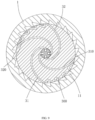
- FIG. 5 is a schematic diagram of a four-stage flow channel. After entering from a first stage flow channel 311, a compressed gas passes through a second stage flow channel 312, a third stage flow channel 313, and a fourth stage flow channel 314, and is ejected and acts on corresponding driving recesses 11, and finally, is output through the exhaust passage 310;
- FIG. 4 is a schematic diagram of a five-stage intake flow channel, and the working process is similar to that shown in FIG. 5 .
- the secondary stroke flow channel 300 includes a return channel and a stroke channel in communication with the return channel, for example, the return channel 3131 and the communicated stroke channel 3132 in the third stage flow channel in FIG. 5 , where the return channel 3131 communicates with a corresponding driving recess of the outer ring, and the stroke channel 3132 communicates with another driving recess.
- the pneumatic device further includes a shaft 2, the outer ring 1 and the core body 3 are coaxially arranged on the shaft 2, the shaft 2 is provided with intake and exhaust shaft passages 21 and 210, they communicate with the intake passage 31 and the exhaust passage 310 of the core body 3, respectively.
- the intake and exhaust shaft passages in the shaft are provided with an inlet (gas inlet) and an outlet (gas outlet), and the intake and exhaust shaft passages are not communicated.
- the outer ring 1 matches with the shaft 2 through side plates 41 and 42 to form a closed space, and the core body 3 is arranged in the closed space and connected and fixed with the shaft 2.
- the core body 3 of the present invention is provided with at least two stages of flow channel, and each stage flow channel communicates with corresponding driving recesses of the outer ring, and finally, the gas is discharged from the exhaust passage.
- the core body 3 of the present invention can be formed by a left core body and a right core body matching with each other, the matching surfaces of the left and right cores bodies are provided with an intake passage 31 and an exhaust passage 310, and the core body 3 can also be cast as a whole.
- this embodiment is a primary driving structure.
- a gas passage is provided on the core body 3 along the circumferential direction to form the primary driving structure, and the gas passage is also called an independent work unit.
- the pneumatic device includes at least one independent work unit. In the independent work unit, the intake passage 31, the nozzle 301, the driving recesses 11, the secondary stroke flow channel 300, the exhaust port 302 and the exhaust passage 310 form a gas flowing path.
- the inner ring surface of the outer ring 1 in the present invention is provided with two or more driving recesses 11, each driving recess has a contour bottom surface 111 and a driving surface 112, a contour line of the contour bottom surface 111 can be a common arc line or a spiral line; when the contour line of the contour bottom surface is a logarithmic spiral line, a pole of the contour bottom surface is set on the shaft 2, and each driving recess 11 communicates with two adjacent stage flow channels at the same time to allow the gas entering from a front stage flow channel to output from a back stage flow channel.
- a running direction of the intake passage, i.e., the first stage flow channel, of the core body 3 of the present invention can be a common arc or spiral line
- the running direction of stroke channel of each secondary stroke flow channel, i.e., the N th stage flow channel can also be a common arc or spiral line.
- the core body 3 of the present invention is provided with an intake passage 31.
- a running direction of the intake passage 31 is a logarithmic spiral line extending from the middle to the outside
- a running direction of the stroke channel of the secondary stroke flow channel 300 is a logarithmic spiral line
- the running direction of the logarithmic spiral line of the stroke channel of the secondary stroke flow channel is roughly the same as the running direction of the logarithmic spiral line of the intake passage.
- the running direction of the intake passage of the core body 3 is the logarithmic spiral line extending from the middle to the outside, and a pole of the logarithmic spiral line is set on a central axis line of the core body, and a strike angle of the logarithmic spiral line is 15°-45°, the smaller the angle, the longer the flow channel, the more loss; the larger the angle, the smaller the tangential force component that drives the outer ring.
- the intake shaft passage 21 and the exhaust shaft passage 210 in the shaft 2 of the present invention form an inlet and an outlet, and the intake and exhaust shaft passages are not communicated.
- the inlet and outlet of the shaft can be arranged at one end of the shaft or at both ends of the shaft, the intake shaft passage 21 communicates with the intake passage 31 of the core body; the outlet of the shaft axially extends to form an exhaust shaft passage 210; and the exhaust shaft passage communicates with the exhaust passage 310 of the core body.
- the pneumatic device involved in this application refers to a device that can convert gas energy into mechanical rotation.
- the device may additionally include other components; for example, it may additionally include, for example, a housing and a sealing structure to provide protection, and for another example, it may additionally include a coupling to provide torque transmission, etc.
- a specific form of the outer ring can be changed according to different output modes of mechanical rotation, for example, an external tooth structure is formed on the outside of the outer ring to facilitate the output of kinetic energy through gear transmission; for another example, the outer ring has a belt groove to facilitate the output of the kinetic energy by belt transmission; for still another example, the outer ring has a mounting flange, so that the coupling can be conveniently installed to output kinetic energy; and so on.
- the core body and the outer ring are made of hard materials, which are not limited to metals, metal alloys, plastics, and composite materials.
- the recess structure or the flow channel structure of the core body and the outer ring can be processed by any known production methods, including but not limited to die casting, forging, extrusion, 3D printing, etc.
- the gas pressure input to the pneumatic device can be produced by a compressor (such as a pneumatic pump), or by a container for compressing a fluid (such as a high-pressure gas bottle), etc.
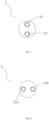
- FIG. 1 and FIG. 4 that the intake passage 31 and the exhaust passage 310 of the core body, and the intake shaft passage 21, and the exhaust shaft passage 210 are not corresponding according to the drawing rules, but for the sake of visual illustration, the intake passage and the exhaust passage of the core body in FIG. 1 do refer to the intake passage and the exhaust passage, and FIG. 6 and FIG. 9 in Embodiment 2 are shown similar to this.
- Embodiment 2 refer to FIGS. 6-9 , the pneumatic device includes two independent work units to form a two-stage driving structure, that is, two gas passages are provided on the core body 3 along the circumferential direction, and each gas passage includes one- or more-stage intake passage 31 and secondary stroke flow channel 300 and the core body 3 are provided with the exhaust passage 310 along the circumferential direction.
- the pneumatic device includes the outer ring 1, the inner ring surface of which is provided with a plurality of driving recesses 11 in the circumferential direction; the core body 3, being coaxially arranged in the outer ring 1 and being capable of rotating relative to the outer ring, where the outer ring surface of the core body is provided with two sets of nozzles and exhaust ports, and at least one secondary stroke flow channel provided between each set of nozzles and exhaust ports, the core body is provided with two intake passages 31, 32 communicating with corresponding nozzles, and two exhaust passages 310, 320 communicating with corresponding exhaust ports.
- the above-mentioned one intake passage, one nozzle, the corresponding number of driving recess and corresponding secondary stroke flow channel, exhaust port and one exhaust passage form an independent work unit.
- the pneumatic device also includes a shaft 2, the outer ring 1 and the core 3 are coaxially arranged on the shaft, the shaft 2 is provided with intake shaft passages 21, 22 and exhaust shaft passages 210, 220, and the intake shaft passages 21, 22 and exhaust shaft passages 210, 220 communicate with the intake passages 31, 32 and the exhaust passages 310, 320 of the core body, respectively.
- the shaft 2 is provided with two inlets and two outlets corresponding to gas passages; compressed gas enters from the two inlets of the shaft 2, and is ejected through the intake passages of the core body 3 to act on the driving recesses 11 of the outer ring 1 to generate a pushing force to push the outer ring 1 to rotate and do work, and finally, the compressed gas arrives at corresponding outlets through the exhaust passages of the core body 3 to achieve a continuous power output.
- Other structures are the same as those in Embodiment 1, and will not be repeated.
- Embodiment 3 the pneumatic device of the present invention includes 4 or more independent work units to form a multi-stage driving structure, and three or more gas passages are provided on the core body in the circumferential direction, and each gas passage includes one- or more-stage intake passage and secondary stroke flow channel, and the exhaust passages are arranged along the circumference direction of the core body, the intake passages and the exhaust passages are arranged on left and right mating surfaces of core body.
- the shaft is provided with intake shaft passages and exhaust shaft passages with the number corresponding to the gas passages.
- Compressed gas enters from the intake shaft passage of the shaft and is ejected through the intake flow channels of the core body to act on the driving recesses of the outer ring to push the outer ring to rotate and do work, so as to realize a continuous power output, and finally, the compressed gas arrives at a corresponding exhaust shaft passage through each exhaust passage of the core body.
- Other structures are the same as those in Embodiment 1.
Landscapes
- Engineering & Computer Science (AREA)
- Mechanical Engineering (AREA)
- General Engineering & Computer Science (AREA)
- Chemical & Material Sciences (AREA)
- Combustion & Propulsion (AREA)
- Jet Pumps And Other Pumps (AREA)
- Actuator (AREA)
Claims (12)
- Dispositif pneumatique comprenantun anneau extérieure (1), comportant une pluralité d'évidements d'entraînement (11) sur une surface intérieure de l'anneau extérieur (1) dans une direction circonférentielle ;un corps central (3), disposé coaxialement dans l'anneau extérieur (1) et capable de tourner par rapport à l'anneau extérieur (1), où une surface de l'anneau extérieur du corps central (3) est pourvue d'au moins une buse (301) et d'au moins un orifice d'échappement (302), le corps central (3) comprenant au moins un canal d'écoulement de la course secondaire (300) entre la buse (301) et l'orifice d'échappement (302) ;au moins un passage d'admission (31), communiquant avec au moins une buse (301) ; etau moins un passage d'échappement (310), communiquant avec au moins un orifice d'échappement (302) ;dans lequel le passage d'admission (31) et le passage d'échappement (310) sont formés à l'intérieur du corps central (3) et dans lequel le corps central (3) comprend :le passage d'admission (31), formant la buse (301) sur une surface périphérique du corps central (3), où une direction d'écoulement du passage d'admission (31) est une ligne d'arc s'étendant d'un milieu à un extérieur, et la buse (301) communique avec un évidement d'entraînement correspondante (11) de l'anneau extérieur (1) pour former un canal d'écoulement de premier étage ; etdans lequel chaque canal d'écoulement de la course secondaire (300), dont la direction de marche est une ligne d'arc s'étendant vers l'intérieur à partir d'un bord du corps central (3) et ensuite incurvée vers le bord, communique avec deux évidements d'entraînement correspondants (11), c'est-à-dire les évidements d'entraînement avant et arrière, de l'anneau extérieur (1) formant un canal d'écoulement à N étapes le long de la direction circonférentielle du corps central (3), où N est un nombre naturel plus grand ou égal à 2 ;chaque canal d'écoulement d'étage correspond à un évidement d'entraînement (11) de l'anneau extérieur (1) pour former une structure de course à plusieurs étages avec une énergie de gaz décroissante ;le canal d'écoulement de la course secondaire (300) comprend un canal de retour (3131) et un canal de course (3132) communiqué avec le canal de retour (3131), le canal de retour (3131) communique avec un évidement d'entraînement correspondante (11) de l'anneau extérieur (1), et le canal de course (3132) communique avec un autre évidement d'entraînement (11) ;dans lequel le dispositif pneumatique est configuré de telle sorte qu'en fonctionnement, un gaz entre par le passage d'admission (31), est éjecté par étapes à travers la buse (301) du corps central (3) et chaque canal d'écoulement de la course secondaire (300), agit sur au moins deux évidements d'entraînement (11) de l'anneau extérieur (1) dans la direction circonférentielle, et génère une force de poussée pour les évidements d'entraînement (11) afin de pousser l'anneau extérieur (1) à tourner et à travailler, de manière à obtenir une puissance de sortie, et enfin, le gaz passe par l'orifice d'échappement (302) du corps central (3) et est évacué par le passage d'échappement (310),caractérisé en ce quechaque canal d'écoulement de la course secondaire (300) comprend un canal de retour (3131), le canal de retour (3131) communique avec un évidement d'entraînement correspondante (11) de l'anneau extérieur (1), et le canal de course (3132) communique avec une autre évidement d'entraînement (11).
- Le dispositif pneumatique selon la revendication 1, caractérisé en ce que, au moins un passage d'admission (31), au moins une buse (301), au moins deux évidements d'entraînement (11), au moins un canal d'écoulement de la course secondaire (300), au moins un orifice d'échappement (302) et au moins un passage d'échappement (310) forment une unité de travail indépendante, le dispositif pneumatique comprend au moins une unité de travail indépendante.
- Le dispositif pneumatique selon la revendication 1, caractérisé en ce que la buse (301) et le canal d'écoulement de la course secondaire (300) sur le corps central (3) communiquent avec un évidement d'entraînement correspondante (11) de l'anneau extérieur (1), et le canal d'écoulement de la course secondaire (300) est disposé le long du corps central (3) ou de l'anneau extérieur (1) dans la direction circonférentielle.
- Le dispositif pneumatique selon la revendication 1, caractérisé en ce qu'une direction de marche du passage d'admission (31) du corps central (3) est une ligne en spirale logarithmique s'étendant d'un milieu à un extérieur, et un pôle de la ligne en spirale logarithmique est fixé sur une ligne d'axe central du corps central (3), et un angle d'attaque de la ligne en spirale logarithmique est de 15°-45°.
- Le dispositif pneumatique selon la revendication 1, caractérisé en ce que le corps central (3) est pourvu d'un passage d'admission (31), et une direction de fonctionnement du passage d'admission (31) est une ligne de spirale logarithmique s'étendant d'un milieu à un extérieur, la direction de marche du canal de course (3132) du canal d'écoulement de la course secondaire (300) est une ligne en spirale logarithmique, et la direction de marche de la ligne en spirale logarithmique du canal de course (3132) du canal d'écoulement de la course secondaire (300) est à peu près la même que la direction de marche de la ligne en spirale logarithmique du passage d'admission (31).
- Le dispositif pneumatique selon la revendication 1, caractérisé en ce que le dispositif pneumatique comprend en outre un arbre (2), et l'anneau extérieur (1) et le corps central (3) sont disposés coaxialement sur l'arbre (2) ;
l'anneau extérieur (1) s'adapte à l'arbre (2) par l'intermédiaire de plaques latérales pour former un espace fermé, et le corps central (3) est disposé dans l'espace fermé et relié et fixé à l'arbre (2). - Le dispositif pneumatique selon la revendication 1, caractérisé en ce que, le dispositif pneumatique comprend en outre un arbre (2), l'anneau extérieur (1) et le corps central (3) sont disposés coaxialement sur l'arbre (2), et l'arbre (2) est pourvu d'un passage d'arbre d'admission (21, 22) et d'un passage d'arbre d'échappement (210, 220), qui sont en communication avec le passage d'admission (31) et le passage d'échappement (310) du corps central (3), respectivement ;
le passage d'arbre d'admission (21, 22) et le passage d'arbre d'échappement (210, 220) dans l'arbre (2) sont pourvus d'une entrée et d'une sortie, et le passage d'arbre d'admission (21, 22) et le passage d'arbre d'échappement (210, 220) ne sont pas communicants. - Le dispositif pneumatique selon la revendication 2, caractérisé en ce que le passage d'admission (31), la buse (301), les évidements d'entraînement (11), le canal d'écoulement de la course secondaire (300), l'orifice d'échappement (302) et le passage d'échappement (310) dans l'unité de travail indépendante forment une voie d'écoulement de gaz.
- Le dispositif pneumatique selon la revendication 2, caractérisé en ce que le dispositif pneumatique comprend deux unités de travail indépendantes ou plus pour former une structure d'entraînement à plusieurs niveaux, et la structure d'entraînement à plusieurs niveaux est disposée le long du corps central (3) ou de l'anneau extérieur (1) dans la direction circonférentielle.
- Le dispositif pneumatique selon la revendication 1, caractérisé en ce que la surface de l'anneau intérieur de l'anneau extérieur (1) est pourvue de deux ou plusieurs évidements d'entraînement (11), et chaque évidement d'entraînement (11) a une surface inférieure de contour (111) et une surface d'entraînement (112), et une ligne de contour de la surface inférieure de contour (111) est une ligne de spirale logarithmique, et un pôle de la ligne de spirale logarithmique est fixé à un centre du corps central (3).
- Moteur pneumatique, caractérisé par le dispositif pneumatique selon l'une des revendications 1 à 10, dans lequel le gaz pour le moteur pneumatique est un gaz comprimé.
- Transmission à variation continue, caractérisée par la présence du dispositif pneumatique selon l'une des revendications 1 à 10.
Applications Claiming Priority (2)
| Application Number | Priority Date | Filing Date | Title |
|---|---|---|---|
| CN201810944526.3A CN110836128B (zh) | 2018-08-19 | 2018-08-19 | 一种气体动力装置 |
| PCT/CN2019/096484 WO2020038164A1 (fr) | 2018-08-19 | 2019-07-18 | Dispositif pneumatique |
Publications (4)
| Publication Number | Publication Date |
|---|---|
| EP3839209A1 EP3839209A1 (fr) | 2021-06-23 |
| EP3839209A4 EP3839209A4 (fr) | 2021-10-13 |
| EP3839209B1 true EP3839209B1 (fr) | 2024-05-08 |
| EP3839209C0 EP3839209C0 (fr) | 2024-05-08 |
Family
ID=69573773
Family Applications (1)
| Application Number | Title | Priority Date | Filing Date |
|---|---|---|---|
| EP19852751.7A Active EP3839209B1 (fr) | 2018-08-19 | 2019-07-18 | Dispositif pneumatique |
Country Status (7)
| Country | Link |
|---|---|
| US (1) | US11441445B2 (fr) |
| EP (1) | EP3839209B1 (fr) |
| JP (1) | JP7128966B2 (fr) |
| CN (1) | CN110836128B (fr) |
| RU (1) | RU2752390C1 (fr) |
| WO (1) | WO2020038164A1 (fr) |
| ZA (1) | ZA202007960B (fr) |
Families Citing this family (2)
| Publication number | Priority date | Publication date | Assignee | Title |
|---|---|---|---|---|
| CN107083994B (zh) * | 2017-06-16 | 2023-03-24 | 传孚科技(厦门)有限公司 | 气压发动机 |
| CN110836128B (zh) * | 2018-08-19 | 2025-01-17 | 传孚科技(厦门)有限公司 | 一种气体动力装置 |
Citations (1)
| Publication number | Priority date | Publication date | Assignee | Title |
|---|---|---|---|---|
| US111538A (en) * | 1871-02-07 | Improvement in double-acting rotary engines |
Family Cites Families (33)
| Publication number | Priority date | Publication date | Assignee | Title |
|---|---|---|---|---|
| US948692A (en) * | 1910-02-08 | Willis G Dodd | Rotary engine. | |
| US925127A (en) * | 1908-11-13 | 1909-06-15 | Alexander Mcdonald | Rotary engine. |
| US1349487A (en) * | 1917-05-31 | 1920-08-10 | Erastus S Bennett | Turbine-engine |
| US3026088A (en) * | 1959-12-03 | 1962-03-20 | Max D Green | Inverted turbine |
| US3761195A (en) * | 1971-05-04 | 1973-09-25 | M Eskeli | Compressing centrifuge |
| WO2000029721A1 (fr) * | 1998-11-13 | 2000-05-25 | Siemens Aktiengesellschaft | Turbomachine, en particulier turbogenerateur comprenant une turbomachine et une machine electrique |
| US7008175B2 (en) * | 2003-06-03 | 2006-03-07 | Saied Fathi | Radiator cooling fan replacement to increase engine efficiency |
| JP2005188378A (ja) * | 2003-12-25 | 2005-07-14 | Takeo Saito | ディスク型半径流タービン |
| JP2006144720A (ja) * | 2004-11-22 | 2006-06-08 | Jungman Yoon | 蒸気タービン |
| US20060225432A1 (en) * | 2005-03-29 | 2006-10-12 | Awdalla Essam T | Supercharged open cycle gas turbine engine |
| JP2010065651A (ja) * | 2008-09-12 | 2010-03-25 | Jungman Yoon | 蒸気タービン装置及びボイラシステム装置 |
| WO2010048730A2 (fr) * | 2008-10-30 | 2010-05-06 | Distributed Thermal Systems Ltd. | Optimiseur d’écoulement multi-étage |
| US8678749B2 (en) * | 2010-01-05 | 2014-03-25 | Takeo S. Saitoh | Centrifugal reverse flow disk turbine and method to obtain rotational power thereby |
| CN104421188A (zh) * | 2013-08-26 | 2015-03-18 | 珠海格力电器股份有限公司 | 多级离心压缩机及空调机组 |
| RU148081U1 (ru) * | 2014-06-27 | 2014-11-27 | Юрий Павлович Кузнецов | Пневматический двигатель |
| CN105443160A (zh) * | 2014-09-06 | 2016-03-30 | 天津重力士净化分离技术有限公司 | 压缩空气驱动的托盘活塞式摇摆发动机头 |
| CN107061103A (zh) * | 2017-06-16 | 2017-08-18 | 传孚科技(厦门)有限公司 | 液压能量转换装置 |
| CN206942813U (zh) * | 2017-06-16 | 2018-01-30 | 传孚科技(厦门)有限公司 | 气压发动机 |
| CN107083994B (zh) | 2017-06-16 | 2023-03-24 | 传孚科技(厦门)有限公司 | 气压发动机 |
| CN208950763U (zh) * | 2018-08-19 | 2019-06-07 | 传孚科技(厦门)有限公司 | 一种泵送系统 |
| CN208929795U (zh) * | 2018-08-19 | 2019-06-04 | 传孚科技(厦门)有限公司 | 一种流体驱动机床 |
| CN209176503U (zh) * | 2018-08-19 | 2019-07-30 | 传孚科技(厦门)有限公司 | 一种气动助力车 |
| CN208946090U (zh) * | 2018-08-19 | 2019-06-07 | 传孚科技(厦门)有限公司 | 一种气动工具 |
| CN209176502U (zh) * | 2018-08-19 | 2019-07-30 | 传孚科技(厦门)有限公司 | 一种气动汽车 |
| CN209179936U (zh) * | 2018-08-19 | 2019-07-30 | 传孚科技(厦门)有限公司 | 一种利用风力进行驱动的动力设备 |
| CN208947094U (zh) * | 2018-08-19 | 2019-06-07 | 传孚科技(厦门)有限公司 | 一种工程车辆 |
| CN209354199U (zh) * | 2018-08-19 | 2019-09-06 | 传孚科技(厦门)有限公司 | 一种气体动力装置 |
| CN208944378U (zh) * | 2018-08-19 | 2019-06-07 | 传孚科技(厦门)有限公司 | 一种流体驱动离心机 |
| CN209179821U (zh) * | 2018-08-19 | 2019-07-30 | 传孚科技(厦门)有限公司 | 一种风力驱动发电机组 |
| CN208950764U (zh) * | 2018-08-19 | 2019-06-07 | 传孚科技(厦门)有限公司 | 一种利用水力进行驱动的动力设备 |
| CN110836128B (zh) * | 2018-08-19 | 2025-01-17 | 传孚科技(厦门)有限公司 | 一种气体动力装置 |
| CN208950593U (zh) * | 2018-08-19 | 2019-06-07 | 传孚科技(厦门)有限公司 | 一种流体驱动掘进装置 |
| CN208940384U (zh) * | 2018-08-19 | 2019-06-07 | 传孚科技(厦门)有限公司 | 一种气动割草机 |
-
2018
- 2018-08-19 CN CN201810944526.3A patent/CN110836128B/zh active Active
-
2019
- 2019-07-18 WO PCT/CN2019/096484 patent/WO2020038164A1/fr not_active Ceased
- 2019-07-18 JP JP2021532505A patent/JP7128966B2/ja active Active
- 2019-07-18 RU RU2020142338A patent/RU2752390C1/ru active
- 2019-07-18 EP EP19852751.7A patent/EP3839209B1/fr active Active
-
2020
- 2020-12-17 US US17/125,784 patent/US11441445B2/en active Active
- 2020-12-18 ZA ZA2020/07960A patent/ZA202007960B/en unknown
Patent Citations (1)
| Publication number | Priority date | Publication date | Assignee | Title |
|---|---|---|---|---|
| US111538A (en) * | 1871-02-07 | Improvement in double-acting rotary engines |
Also Published As
| Publication number | Publication date |
|---|---|
| CN110836128A (zh) | 2020-02-25 |
| US20210115810A1 (en) | 2021-04-22 |
| JP7128966B2 (ja) | 2022-08-31 |
| EP3839209A4 (fr) | 2021-10-13 |
| WO2020038164A1 (fr) | 2020-02-27 |
| RU2752390C1 (ru) | 2021-07-27 |
| EP3839209A1 (fr) | 2021-06-23 |
| ZA202007960B (en) | 2022-04-28 |
| JP2021533306A (ja) | 2021-12-02 |
| US11441445B2 (en) | 2022-09-13 |
| EP3839209C0 (fr) | 2024-05-08 |
| CN110836128B (zh) | 2025-01-17 |
Similar Documents
| Publication | Publication Date | Title |
|---|---|---|
| JP6408027B2 (ja) | 偏心可動羽根ポンプ | |
| US11441445B2 (en) | Pneumatic device | |
| CN107083994B (zh) | 气压发动机 | |
| US20230056477A1 (en) | Power device capable of generating greater propelling force | |
| CN104196719A (zh) | 一种多级内啮合航空燃油齿轮泵 | |
| CN214660844U (zh) | 一种两极压缩螺杆主机 | |
| CN101825041A (zh) | 气体活塞脉冲发动机 | |
| CN208946090U (zh) | 一种气动工具 | |
| CN110832984B (zh) | 一种气动割草机 | |
| CN110834534B (zh) | 一种气动助力车 | |
| CN209354199U (zh) | 一种气体动力装置 | |
| US3396532A (en) | Combustion air system | |
| CN110836258B (zh) | 一种液压动力装置 | |
| CN209818301U (zh) | 一种共用驱动轴的多级真空泵 | |
| US5865608A (en) | Air flow system for circular rotary type engines | |
| CN110833934B (zh) | 一种流体驱动离心机 | |
| CN110857682A (zh) | 一种利用风力进行驱动的动力设备 | |
| CN114483594A (zh) | 一种双端多级多功能集成式燃油泵 | |
| CN110836159B (zh) | 一种泵送系统 | |
| WO2001002701A1 (fr) | Machine de compression centrifuge et dynamique d'un fluide | |
| CN110834305A (zh) | 一种气动工具 | |
| CN209385183U (zh) | 一种紧凑型四级涡轮机 | |
| CN110834535A (zh) | 一种气动汽车 | |
| CN110834536B (zh) | 一种工程车辆 | |
| US3005307A (en) | Exhaust pulse equalizing energy converters for rotary combustion engines |
Legal Events
| Date | Code | Title | Description |
|---|---|---|---|
| STAA | Information on the status of an ep patent application or granted ep patent |
Free format text: STATUS: THE INTERNATIONAL PUBLICATION HAS BEEN MADE |
|
| PUAI | Public reference made under article 153(3) epc to a published international application that has entered the european phase |
Free format text: ORIGINAL CODE: 0009012 |
|
| STAA | Information on the status of an ep patent application or granted ep patent |
Free format text: STATUS: REQUEST FOR EXAMINATION WAS MADE |
|
| 17P | Request for examination filed |
Effective date: 20210319 |
|
| AK | Designated contracting states |
Kind code of ref document: A1 Designated state(s): AL AT BE BG CH CY CZ DE DK EE ES FI FR GB GR HR HU IE IS IT LI LT LU LV MC MK MT NL NO PL PT RO RS SE SI SK SM TR |
|
| A4 | Supplementary search report drawn up and despatched |
Effective date: 20210915 |
|
| RIC1 | Information provided on ipc code assigned before grant |
Ipc: F01D 25/00 20060101ALI20210909BHEP Ipc: F01D 1/02 20060101AFI20210909BHEP |
|
| DAV | Request for validation of the european patent (deleted) | ||
| DAX | Request for extension of the european patent (deleted) | ||
| STAA | Information on the status of an ep patent application or granted ep patent |
Free format text: STATUS: EXAMINATION IS IN PROGRESS |
|
| 17Q | First examination report despatched |
Effective date: 20230510 |
|
| GRAP | Despatch of communication of intention to grant a patent |
Free format text: ORIGINAL CODE: EPIDOSNIGR1 |
|
| STAA | Information on the status of an ep patent application or granted ep patent |
Free format text: STATUS: GRANT OF PATENT IS INTENDED |
|
| INTG | Intention to grant announced |
Effective date: 20240124 |
|
| GRAS | Grant fee paid |
Free format text: ORIGINAL CODE: EPIDOSNIGR3 |
|
| GRAA | (expected) grant |
Free format text: ORIGINAL CODE: 0009210 |
|
| STAA | Information on the status of an ep patent application or granted ep patent |
Free format text: STATUS: THE PATENT HAS BEEN GRANTED |
|
| RAP3 | Party data changed (applicant data changed or rights of an application transferred) |
Owner name: TRANF TECHNOLOGY (XIAMEN) CO., LTD |
|
| AK | Designated contracting states |
Kind code of ref document: B1 Designated state(s): AL AT BE BG CH CY CZ DE DK EE ES FI FR GB GR HR HU IE IS IT LI LT LU LV MC MK MT NL NO PL PT RO RS SE SI SK SM TR |
|
| REG | Reference to a national code |
Ref country code: GB Ref legal event code: FG4D |
|
| REG | Reference to a national code |
Ref country code: CH Ref legal event code: EP |
|
| REG | Reference to a national code |
Ref country code: DE Ref legal event code: R096 Ref document number: 602019052065 Country of ref document: DE |
|
| REG | Reference to a national code |
Ref country code: IE Ref legal event code: FG4D |
|
| U01 | Request for unitary effect filed |
Effective date: 20240524 |
|
| U07 | Unitary effect registered |
Designated state(s): AT BE BG DE DK EE FI FR IT LT LU LV MT NL PT SE SI Effective date: 20240606 |
|
| U20 | Renewal fee for the european patent with unitary effect paid |
Year of fee payment: 6 Effective date: 20240807 |
|
| PG25 | Lapsed in a contracting state [announced via postgrant information from national office to epo] |
Ref country code: IS Free format text: LAPSE BECAUSE OF FAILURE TO SUBMIT A TRANSLATION OF THE DESCRIPTION OR TO PAY THE FEE WITHIN THE PRESCRIBED TIME-LIMIT Effective date: 20240908 |
|
| PG25 | Lapsed in a contracting state [announced via postgrant information from national office to epo] |
Ref country code: HR Free format text: LAPSE BECAUSE OF FAILURE TO SUBMIT A TRANSLATION OF THE DESCRIPTION OR TO PAY THE FEE WITHIN THE PRESCRIBED TIME-LIMIT Effective date: 20240508 |
|
| PG25 | Lapsed in a contracting state [announced via postgrant information from national office to epo] |
Ref country code: GR Free format text: LAPSE BECAUSE OF FAILURE TO SUBMIT A TRANSLATION OF THE DESCRIPTION OR TO PAY THE FEE WITHIN THE PRESCRIBED TIME-LIMIT Effective date: 20240809 |
|
| PGFP | Annual fee paid to national office [announced via postgrant information from national office to epo] |
Ref country code: GB Payment date: 20240725 Year of fee payment: 6 |
|
| PG25 | Lapsed in a contracting state [announced via postgrant information from national office to epo] |
Ref country code: ES Free format text: LAPSE BECAUSE OF FAILURE TO SUBMIT A TRANSLATION OF THE DESCRIPTION OR TO PAY THE FEE WITHIN THE PRESCRIBED TIME-LIMIT Effective date: 20240508 |
|
| PG25 | Lapsed in a contracting state [announced via postgrant information from national office to epo] |
Ref country code: PL Free format text: LAPSE BECAUSE OF FAILURE TO SUBMIT A TRANSLATION OF THE DESCRIPTION OR TO PAY THE FEE WITHIN THE PRESCRIBED TIME-LIMIT Effective date: 20240508 |
|
| PG25 | Lapsed in a contracting state [announced via postgrant information from national office to epo] |
Ref country code: PL Free format text: LAPSE BECAUSE OF FAILURE TO SUBMIT A TRANSLATION OF THE DESCRIPTION OR TO PAY THE FEE WITHIN THE PRESCRIBED TIME-LIMIT Effective date: 20240508 Ref country code: NO Free format text: LAPSE BECAUSE OF FAILURE TO SUBMIT A TRANSLATION OF THE DESCRIPTION OR TO PAY THE FEE WITHIN THE PRESCRIBED TIME-LIMIT Effective date: 20240808 Ref country code: IS Free format text: LAPSE BECAUSE OF FAILURE TO SUBMIT A TRANSLATION OF THE DESCRIPTION OR TO PAY THE FEE WITHIN THE PRESCRIBED TIME-LIMIT Effective date: 20240908 Ref country code: HR Free format text: LAPSE BECAUSE OF FAILURE TO SUBMIT A TRANSLATION OF THE DESCRIPTION OR TO PAY THE FEE WITHIN THE PRESCRIBED TIME-LIMIT Effective date: 20240508 Ref country code: GR Free format text: LAPSE BECAUSE OF FAILURE TO SUBMIT A TRANSLATION OF THE DESCRIPTION OR TO PAY THE FEE WITHIN THE PRESCRIBED TIME-LIMIT Effective date: 20240809 Ref country code: ES Free format text: LAPSE BECAUSE OF FAILURE TO SUBMIT A TRANSLATION OF THE DESCRIPTION OR TO PAY THE FEE WITHIN THE PRESCRIBED TIME-LIMIT Effective date: 20240508 Ref country code: RS Free format text: LAPSE BECAUSE OF FAILURE TO SUBMIT A TRANSLATION OF THE DESCRIPTION OR TO PAY THE FEE WITHIN THE PRESCRIBED TIME-LIMIT Effective date: 20240808 |
|
| PG25 | Lapsed in a contracting state [announced via postgrant information from national office to epo] |
Ref country code: CZ Free format text: LAPSE BECAUSE OF FAILURE TO SUBMIT A TRANSLATION OF THE DESCRIPTION OR TO PAY THE FEE WITHIN THE PRESCRIBED TIME-LIMIT Effective date: 20240508 |
|
| PG25 | Lapsed in a contracting state [announced via postgrant information from national office to epo] |
Ref country code: SK Free format text: LAPSE BECAUSE OF FAILURE TO SUBMIT A TRANSLATION OF THE DESCRIPTION OR TO PAY THE FEE WITHIN THE PRESCRIBED TIME-LIMIT Effective date: 20240508 Ref country code: RO Free format text: LAPSE BECAUSE OF FAILURE TO SUBMIT A TRANSLATION OF THE DESCRIPTION OR TO PAY THE FEE WITHIN THE PRESCRIBED TIME-LIMIT Effective date: 20240508 |
|
| PG25 | Lapsed in a contracting state [announced via postgrant information from national office to epo] |
Ref country code: SM Free format text: LAPSE BECAUSE OF FAILURE TO SUBMIT A TRANSLATION OF THE DESCRIPTION OR TO PAY THE FEE WITHIN THE PRESCRIBED TIME-LIMIT Effective date: 20240508 |
|
| PG25 | Lapsed in a contracting state [announced via postgrant information from national office to epo] |
Ref country code: SM Free format text: LAPSE BECAUSE OF FAILURE TO SUBMIT A TRANSLATION OF THE DESCRIPTION OR TO PAY THE FEE WITHIN THE PRESCRIBED TIME-LIMIT Effective date: 20240508 Ref country code: SK Free format text: LAPSE BECAUSE OF FAILURE TO SUBMIT A TRANSLATION OF THE DESCRIPTION OR TO PAY THE FEE WITHIN THE PRESCRIBED TIME-LIMIT Effective date: 20240508 Ref country code: RO Free format text: LAPSE BECAUSE OF FAILURE TO SUBMIT A TRANSLATION OF THE DESCRIPTION OR TO PAY THE FEE WITHIN THE PRESCRIBED TIME-LIMIT Effective date: 20240508 Ref country code: CZ Free format text: LAPSE BECAUSE OF FAILURE TO SUBMIT A TRANSLATION OF THE DESCRIPTION OR TO PAY THE FEE WITHIN THE PRESCRIBED TIME-LIMIT Effective date: 20240508 |
|
| PG25 | Lapsed in a contracting state [announced via postgrant information from national office to epo] |
Ref country code: MC Free format text: LAPSE BECAUSE OF FAILURE TO SUBMIT A TRANSLATION OF THE DESCRIPTION OR TO PAY THE FEE WITHIN THE PRESCRIBED TIME-LIMIT Effective date: 20240508 |
|
| REG | Reference to a national code |
Ref country code: DE Ref legal event code: R097 Ref document number: 602019052065 Country of ref document: DE |
|
| REG | Reference to a national code |
Ref country code: CH Ref legal event code: PL |
|
| PLBE | No opposition filed within time limit |
Free format text: ORIGINAL CODE: 0009261 |
|
| STAA | Information on the status of an ep patent application or granted ep patent |
Free format text: STATUS: NO OPPOSITION FILED WITHIN TIME LIMIT |
|
| 26N | No opposition filed |
Effective date: 20250211 |
|
| PG25 | Lapsed in a contracting state [announced via postgrant information from national office to epo] |
Ref country code: CH Free format text: LAPSE BECAUSE OF NON-PAYMENT OF DUE FEES Effective date: 20240731 |
|
| PG25 | Lapsed in a contracting state [announced via postgrant information from national office to epo] |
Ref country code: IE Free format text: LAPSE BECAUSE OF NON-PAYMENT OF DUE FEES Effective date: 20240718 |
|
| PG25 | Lapsed in a contracting state [announced via postgrant information from national office to epo] |
Ref country code: CY Free format text: LAPSE BECAUSE OF FAILURE TO SUBMIT A TRANSLATION OF THE DESCRIPTION OR TO PAY THE FEE WITHIN THE PRESCRIBED TIME-LIMIT; INVALID AB INITIO Effective date: 20190718 |
|
| PG25 | Lapsed in a contracting state [announced via postgrant information from national office to epo] |
Ref country code: HU Free format text: LAPSE BECAUSE OF FAILURE TO SUBMIT A TRANSLATION OF THE DESCRIPTION OR TO PAY THE FEE WITHIN THE PRESCRIBED TIME-LIMIT; INVALID AB INITIO Effective date: 20190718 |
|
| GBPC | Gb: european patent ceased through non-payment of renewal fee |
Effective date: 20250718 |
|
| U90 | Renewal fees not paid: noting of loss of rights |
Free format text: RENEWAL FEE NOT PAID FOR YEAR 07 Effective date: 20260223 |
|
| PG25 | Lapsed in a contracting state [announced via postgrant information from national office to epo] |
Ref country code: GB Free format text: LAPSE BECAUSE OF NON-PAYMENT OF DUE FEES Effective date: 20250718 |