EP3839239B1 - Verbrennungsmotor mit ansaugkrümmer mit integrierter kurbelgehäuseentlüftungsgaserücklaufleitung - Google Patents
Verbrennungsmotor mit ansaugkrümmer mit integrierter kurbelgehäuseentlüftungsgaserücklaufleitung Download PDFInfo
- Publication number
- EP3839239B1 EP3839239B1 EP20212384.0A EP20212384A EP3839239B1 EP 3839239 B1 EP3839239 B1 EP 3839239B1 EP 20212384 A EP20212384 A EP 20212384A EP 3839239 B1 EP3839239 B1 EP 3839239B1
- Authority
- EP
- European Patent Office
- Prior art keywords
- intake
- ramp
- distributor
- cylinder head
- combustion engine
- Prior art date
- Legal status (The legal status is an assumption and is not a legal conclusion. Google has not performed a legal analysis and makes no representation as to the accuracy of the status listed.)
- Active
Links
Images



Classifications
-
- F—MECHANICAL ENGINEERING; LIGHTING; HEATING; WEAPONS; BLASTING
- F02—COMBUSTION ENGINES; HOT-GAS OR COMBUSTION-PRODUCT ENGINE PLANTS
- F02M—SUPPLYING COMBUSTION ENGINES IN GENERAL WITH COMBUSTIBLE MIXTURES OR CONSTITUENTS THEREOF
- F02M35/00—Combustion-air cleaners, air intakes, intake silencers, or induction systems specially adapted for, or arranged on, internal-combustion engines
- F02M35/10—Air intakes; Induction systems
- F02M35/10209—Fluid connections to the air intake system; their arrangement of pipes, valves or the like
- F02M35/10222—Exhaust gas recirculation [EGR]; Positive crankcase ventilation [PCV]; Additional air admission, lubricant or fuel vapour admission
-
- F—MECHANICAL ENGINEERING; LIGHTING; HEATING; WEAPONS; BLASTING
- F01—MACHINES OR ENGINES IN GENERAL; ENGINE PLANTS IN GENERAL; STEAM ENGINES
- F01M—LUBRICATING OF MACHINES OR ENGINES IN GENERAL; LUBRICATING INTERNAL COMBUSTION ENGINES; CRANKCASE VENTILATING
- F01M13/00—Crankcase ventilating or breathing
- F01M13/0011—Breather valves
-
- F—MECHANICAL ENGINEERING; LIGHTING; HEATING; WEAPONS; BLASTING
- F01—MACHINES OR ENGINES IN GENERAL; ENGINE PLANTS IN GENERAL; STEAM ENGINES
- F01M—LUBRICATING OF MACHINES OR ENGINES IN GENERAL; LUBRICATING INTERNAL COMBUSTION ENGINES; CRANKCASE VENTILATING
- F01M13/00—Crankcase ventilating or breathing
- F01M13/02—Crankcase ventilating or breathing by means of additional source of positive or negative pressure
- F01M13/021—Crankcase ventilating or breathing by means of additional source of positive or negative pressure of negative pressure
- F01M13/022—Crankcase ventilating or breathing by means of additional source of positive or negative pressure of negative pressure using engine inlet suction
- F01M13/023—Control valves in suction conduit
-
- F—MECHANICAL ENGINEERING; LIGHTING; HEATING; WEAPONS; BLASTING
- F02—COMBUSTION ENGINES; HOT-GAS OR COMBUSTION-PRODUCT ENGINE PLANTS
- F02M—SUPPLYING COMBUSTION ENGINES IN GENERAL WITH COMBUSTIBLE MIXTURES OR CONSTITUENTS THEREOF
- F02M25/00—Engine-pertinent apparatus for adding non-fuel substances or small quantities of secondary fuel to combustion-air, main fuel or fuel-air mixture
- F02M25/06—Engine-pertinent apparatus for adding non-fuel substances or small quantities of secondary fuel to combustion-air, main fuel or fuel-air mixture adding lubricant vapours
-
- F—MECHANICAL ENGINEERING; LIGHTING; HEATING; WEAPONS; BLASTING
- F02—COMBUSTION ENGINES; HOT-GAS OR COMBUSTION-PRODUCT ENGINE PLANTS
- F02M—SUPPLYING COMBUSTION ENGINES IN GENERAL WITH COMBUSTIBLE MIXTURES OR CONSTITUENTS THEREOF
- F02M35/00—Combustion-air cleaners, air intakes, intake silencers, or induction systems specially adapted for, or arranged on, internal-combustion engines
- F02M35/10—Air intakes; Induction systems
- F02M35/104—Intake manifolds
- F02M35/1042—Intake manifolds characterised by provisions to avoid mixture or air supply from one plenum chamber to two successively firing cylinders
-
- F—MECHANICAL ENGINEERING; LIGHTING; HEATING; WEAPONS; BLASTING
- F02—COMBUSTION ENGINES; HOT-GAS OR COMBUSTION-PRODUCT ENGINE PLANTS
- F02M—SUPPLYING COMBUSTION ENGINES IN GENERAL WITH COMBUSTIBLE MIXTURES OR CONSTITUENTS THEREOF
- F02M35/00—Combustion-air cleaners, air intakes, intake silencers, or induction systems specially adapted for, or arranged on, internal-combustion engines
- F02M35/10—Air intakes; Induction systems
- F02M35/10006—Air intakes; Induction systems characterised by the position of elements of the air intake system in direction of the air intake flow, i.e. between ambient air inlet and supply to the combustion chamber
- F02M35/10078—Connections of intake systems to the engine
-
- Y—GENERAL TAGGING OF NEW TECHNOLOGICAL DEVELOPMENTS; GENERAL TAGGING OF CROSS-SECTIONAL TECHNOLOGIES SPANNING OVER SEVERAL SECTIONS OF THE IPC; TECHNICAL SUBJECTS COVERED BY FORMER USPC CROSS-REFERENCE ART COLLECTIONS [XRACs] AND DIGESTS
- Y02—TECHNOLOGIES OR APPLICATIONS FOR MITIGATION OR ADAPTATION AGAINST CLIMATE CHANGE
- Y02T—CLIMATE CHANGE MITIGATION TECHNOLOGIES RELATED TO TRANSPORTATION
- Y02T10/00—Road transport of goods or passengers
- Y02T10/10—Internal combustion engine [ICE] based vehicles
- Y02T10/12—Improving ICE efficiencies
Definitions
- the present invention relates to an internal combustion engine.
- the present invention also relates to a motor vehicle equipped with a heat engine with a device for indirect injection of gas or fuel into an air intake circuit of said engine.
- the present invention relates more particularly to an arrangement for fixing an intake air distributor against a heat engine cylinder head.
- a motor vehicle is experiencing more and more constraints to reduce the size of its equipment for reasons of aesthetics or passenger comfort.
- the vehicle equipped with a thermal engine also called internal combustion comprises an engine compartment in which is housed a powertrain comprising the engine and its elements or accessories, the dimensions of which are increasingly reduced leading to research into improvements in terms of compactness of the engine and its elements or accessories.
- a heat engine comprises, in known manner, a cylinder block on which a cylinder head is mounted. Air intake ducts are dug into said cylinder head which lead to the cylinders.
- the cylinder head has a so-called “intake” face against which is fixed an intake distributor capable of directing air or intake gases towards the intake ducts dug in the cylinder head and connected with the cylinders, and a face called “exhaust” against which an exhaust manifold is fixed to recover the burnt gases resulting from combustion in the engine cylinders.
- the air and/or the intake gases are directed towards the intake distributor having been previously compressed as they pass through a compressor which is for example the compression stage of a turbocharger.
- a cooler stage is installed in the air intake circuit upstream of the cylinder head according to the direction of circulation of the intake air.
- This cooler stage includes, for example, an air/water exchanger through which the hot compressed air transfers part of its heat to water or a cooling liquid.
- the heat exchanger is housed in a casing which is extended downstream by a fixing flange in the direction of circulation of the intake air, forming a chamber with, for example, a recess in the cylinder head. Said chamber forms an intake distributor plenum.
- crankcase is fixed against the intake face of the cylinder head using the flange.
- the fixing of this casing must meet strong mechanical constraints which require parts of high rigidity made of metallic material such as steel or steel alloy or aluminum alloy or technical plastic.
- said casing is fixed in an oblique direction relative to the intake face of the cylinder head.
- Said intake face extends substantially along a vertical plane.
- Engines with indirect liquid fuel or gas injection have a liquid fuel or gas injection conduit in the air intake circuit. Injection is generally carried out upstream of the engine cylinders in air intake ducts dug into the cylinder head.
- fuel or gas injection conduits are pierced from an intake face of the cylinder head to open obliquely into an air intake channel.
- the fuel is thus mixed with the intake air before its introduction into a combustion chamber upon opening an access controlled by an intake valve.
- Said combustion chamber is delimited by the longitudinal wall of the cylinder, a piston and a lower wall of the cylinder head.
- Access to the exhaust pipes is controlled by exhaust valves.
- Opening and closing access to the intake and exhaust ducts can result in backflow of air flows at the intake.
- Said backflows are known as “back-flow” in English. Said backflows do not concern all of the intake conduits at the same time and can occur randomly in one of the intake conduits up to the intake plenum. Backflow must be controlled because on the one hand the gases can contain fuel and on the other hand modify the operating conditions of the engine. In fact, reflux can go up into the deoiled gas injection channels.
- the publication FR2884875-A1 proposes a scavenging duct opening into the combustion chamber and connected to the air intake circuit and controlled by a scavenging valve arranged upstream according to the direction of circulation of the intake air.
- a disadvantage concerns the opening system of the scavenging valve and its arrangement.
- the aim of the invention to remedy these problems and the object of the invention is an arrangement for fixing a heat exchanger, in particular an intake distributor to an intake wall of a cylinder head.
- heat engine with indirect injection of fuel or gas said distributor is connected upstream to an air intake circuit and downstream to intake ducts dug in the cylinder head and includes de-oiled gas intake ports , said arrangement allows airflow insulation of each of the intake ducts and control of gas backflow at the intake.
- the present invention relates to an arrangement for fixing an air intake circuit to an intake wall of a cylinder head of a heat engine with indirect fuel injection.
- the present invention relates more particularly to an air intake distributor for a heat engine with indirect fuel injection which comprises a cylinder head in which tubular intake ducts are dug which open on one side into an intake chamber surrounded by the intake distributor, and on the opposite side in a combustion chamber delimited by a cylinder, a piston and the lower wall of the cylinder head, said distributor comprising inlet orifices of a deoiled gas supply rail, characterized in that the admission chamber is divided into compartments, each of which is dedicated to each cylinder and which includes a device for admitting deoiled gases capable of controlling the airtightness between two neighboring compartments.
- the intake chamber or plenum of gas and air intake is divided into compartments, each of said compartments is dedicated to a particular cylinder, that is to say connected to a particular cylinder to bring the air and gases recirculated in the combustion chamber delimited by said cylinder.
- the inlet chamber is covered by a distributor or by a distributor mounting flange.
- the intake chamber is divided into compartments by at least one separation wall which extends parallel to the axis of air flow and gas and orthogonal to the cylinder head fixing wall.
- Each compartment communicates with a single specific combustion chamber. We thus obtain a distinct air flow per station or per combustion chamber in order to isolate the risk of backflow per station and not impact neighboring stations.
- Each compartment includes a specific de-oiled gas admission device capable of controlling the tightness with respect to the neighboring compartment, in particular capable of avoiding gas communications through the de-oiled gas inlet orifices.
- the device comprises a non-return valve disposed in a supply conduit connected to the supply ramp on one side and to the intake chamber on the opposite side to prevent the passage of gas flows from compartment towards the ramp and to allow the flow of deoiled gases from the chamber towards the compartment, while having as little impact as possible on the main flow of air and intake gas in the plenum towards the ducts intake of the cylinder head.
- the upper sealing ring carries the elastic means for controlling the passage of gas flow thus ensuring with a single piece airtightness and control of the passage of gas flow.
- vertical axis denotes an axis orthogonal to the lower plane of contact of the cylinder head with a cylinder block, the axis being turned upwards away from the cylinder block.
- a vehicle heat engine is supplied with air by an intake circuit.
- air is captured from the front face of the vehicle and conducted to an intake wall of the engine, in particular a cylinder head of said engine.
- the air can pass for example through an air filter, through a compression stage which may be a compressor of a turbo-compressor.
- the intake air is then cooled to ensure better engine efficiency, passing through a heat exchanger 50 as shown in figure 1 , generally of the water/air type by which the air transfers part of its heat to a water-based coolant.
- the air is brought into an intake distributor 10 which is fixed against the intake wall 51 of the cylinder head 50 of the engine.
- the distributor 10 comprises a plenum or intake or distribution chamber 11 connected to combustion chambers 53 of the engine via intake channels 52 dug into the cylinder head.
- Each of said rooms combustion is delimited by a cylinder hollowed out in a cylinder block, a piston which is movable in sliding along the axis of the cylinder and an underside of the cylinder head.
- Our invention relates to an indirect injection heat engine.
- the fuel is injected by an injector into an air intake channel 60, more precisely, the injector is housed in an injection conduit 54 which opens into an air intake channel 52 of the cylinder head 50.
- the plenum 11 is composed of a recess 55 in the intake wall of the cylinder head and by a chamber 12 delimited by the walls of the intake distributor 10 covering the recess.
- the intake channels 52 dug in the cylinder head therefore open into the recess 55.
- Said recess 55 is divided by at least one separation wall 56, into at least one intake cavity 57.
- Each of the cavities 57 is connected to a single combustion chamber 53 by the intake channels 52, and said chamber combustion chamber is only connected to a single intake cavity 57.
- the couple intake cavity, combustion chamber
- the separation wall 56 extends from the surface of the recess 55 of the cylinder head outwards, parallel to a plane formed by the intake air flow axis X and a vertical axis Z. The direction of air flow is indicated by an arrow.
- a heat exchanger 70 is fixed against the inlet wall 51 of the cylinder head 50 by a fixing flange 10.
- Said fixing flange 10 surrounds an air passage space 13 having an air passage section 14 substantially rectangular and delimited by a lower wall 15, an upper wall 16 facing the lower wall and two side walls 17 orthogonal to said lower 15 and upper 16 walls.
- the side walls 17 are in the shape of a trapezoid to allow attachment oblique from the heat exchanger 70 to the vertical inlet wall 51 of the cylinder head 50.
- the flange acts as a distributor 10 and the plenum includes the air passage space 13.
- the names flange or distributor to define the same part which ensures the fixing of the exchanger and which allows the mixing gases before their admission into the intake channels of the cylinder head, depending on the function provided.
- the flange 10 comprises a peripheral fixing curb 18 which is intended to bear against the inlet wall 51 of the cylinder head.
- a peripheral fixing curb 18 which is intended to bear against the inlet wall 51 of the cylinder head.
- through holes are provided to receive fixing screws which are pressed into the inlet wall 51 of the cylinder head.
- the distributor 10 comprises interior partition walls 19 substantially parallel to the side walls 17, said interior partitions 19 are an extension of the separation walls 56 in the recess 55 of the cylinder head.
- the interior partitions 19 divide the air passage space 13 into air passage compartments 20.
- each compartment 20 is aeraulically isolated from the neighboring compartment and is connected to a single cavity 57 for admitting the cylinder head and therefore to a single combustion chamber 53 when the distributor is mounted fixed against the cylinder head.
- the intake cavity 57 of the cylinder head is a substantially rectilinear extension of the passage compartment 20 of the distributor 10.
- an air seal is arranged between the distributor 10 and the inlet wall 51 of the cylinder head 50. More precisely, the passage section of the distributor is surrounded by the seal as shown in Figure 3 And 7 .
- a supply ramp 21 of deoiled gases is dug in the lower wall 15 of the flange 10. Said ramp 21 is more precisely formed by a trench dug in the fixing pavement 18. The ramp therefore has an opening 21l extending over the entire length of the feed ramp 21 and intended opposite the fixing wall 51 of the cylinder head 50.
- the supply ramp 21 is extended transversely to its axis by deoiled gas supply conduits 22 which open from the lower wall 15 into the plenum 11 via deoiled gas openings 23.
- the diameter of the openings is l of the order of a few millimeters, for example 5 mm.
- the openings 23 of the supply conduits 22 in the plenum 11 are controlled by an admission device 100 for the deoiled gases. This device ensures airtightness of each passage compartment 20.
- the peripheral pavement 18 includes a peripheral groove 24 intended to accommodate a seal 30.
- the power supply ramp 21 connected to all the compartments 20 through which the plenum passes is sealed with respect to the plenum 11.
- the lower wall 15 of the distributor 10 comprises an upper edge 15s delimiting the plenum and a lower edge 15i facing the outside of the distributor.
- the peripheral groove 24 comprises two branches of grooves 25, 26 each capable of accommodating a sealing ring 31, 32 and completely surrounding the supply ramp 21.
- a first groove 25 extends transversely to the gas flow axis, substantially parallel to the supply ramp 21 and it is arranged between the supply ramp 21 and the upper edge 15s of the lower wall 15.
- a second groove 32 surrounds the ramp 21 and also extends transversely to the axis of flow of gases and intake air, substantially parallel to the feed ramp 21; it is arranged between the feed ramp 21 and the lower edge 15i of the lower wall 15.
- a first sealing ring 31 is placed in the first groove 25.
- the first ring ensures the sealing of the plenum 11 with respect to the supply ramp 21.
- a second sealing ring 32 is placed in the second groove 26. The second ring 32 ensures the sealing of the lower part of the distributor, in particular of the ramp 21 of deoiled gases with respect to the exterior of the distributor.
- the device 100 comprises an elastic means 33 which tilts from a rest position where it closes the inlet opening 23 of the deoiled gases to an open position where gas passages are authorized from the ramp supply 21 to plenum 11.
- the device 100 comprises an elastic membrane 34, for example made of elastomer, covering the opening 23 for the deoiled gases.
- Said membrane 34 is arranged against the lower wall 15 of the distributor, in the plenum 11. Said membrane is able to deform by suction and release the opening 23.
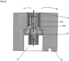
- the device 100 comprises a non-return valve 35 installed in each supply conduit 22, preferably so as not to overflow into the plenum 11 and thus avoid any impact on the air intake flows into the compartment 24 air passage.
- the check valve can be of any shape; for example it can consist of a mouth 35b surrounded by lips 35l which are able to separate to allow the passage of deoiled gases or come together to close the opening.
- the device 100 is part of the seal 30 disposed between the distributor 10 and the cylinder head 50.
- the first ring 31 carries for example the non-return valves 27 which are installed in grooves transverse to the first groove 30 forming the conduits supply of deoiled gases, and which open from the lower wall 15 into the plenum 11.
- the seal and in particular the first ring is capable of ensuring on the one hand the sealing a Vogellic of the supply ramp 21 vis-à-vis the plenum 11 and on the other hand to control the passage of gases from said ramp towards the plenum.
- each air passage compartment 24 is aeraulically isolated from the neighboring compartment(s).
- the deoiled gas supply ramp 21 being connected to all the passage compartments 24 no longer presents a risk of aeraulic connection between compartments 24.
- the intake device allows the passage of deoiled gases during the opening phases of the intake valves during which a depression of up to 800 mbar can be observed.
- the elastic membrane is sucked in, which causes the passage of de-oiled gases whose pressure level is of the order of 950 mbar.
- the deoiled gases are then sucked into the intake channels of the cylinder head.
- the lips of the non-return valve separate due to the pressure difference between the supply rail and the plenum to allow the deoiled gases to be sucked in and pass through the 'opening.
- the pressure in the plenum is greater than the pressure in the supply rail and, depending on the embodiment, presses the membrane on the lower wall 15 of the distributor or presses the lips of the valve one against the other to close the opening of the outlet of the supply conduit.
- the de-oiled gas admission device 100 can easily and at low cost control the airtightness of each air passage compartment 24, in particular by closing the inlet ducts 22 during the discharge phases .
- the device 100 may include tilting shutters allowing opening during the suction and closing phases.
- the seal may be a silicone-based seal deposited on the surface of the fixing pavement and not requiring a peripheral groove.
- the cylinder head does not have a recess which is part of the plenum and the intake channels open directly into the distributor.
Landscapes
- Engineering & Computer Science (AREA)
- Mechanical Engineering (AREA)
- General Engineering & Computer Science (AREA)
- Chemical & Material Sciences (AREA)
- Combustion & Propulsion (AREA)
- Cylinder Crankcases Of Internal Combustion Engines (AREA)
- Lubrication Details And Ventilation Of Internal Combustion Engines (AREA)
- Fuel-Injection Apparatus (AREA)
Claims (7)
- Verbrennungsmotor mit indirekter Kraftstoffeinspritzung, mit einem Luftansaugverteiler (10) des Verbrennungsmotors mit indirekter Kraftstoffeinspritzung, der umfasst: einen Zylinderkopf (50), in dem rohrförmige Einlasskanäle (52) ausgehöhlt sind, die auf einer Seite in eine Einlasskammer (11) münden, die von dem Einlassverteiler umgeben ist, und auf der gegenüberliegenden Seite in eine Verbrennungskammer (53), die durch einen Zylinder, einen Kolben und die untere Wand des Zylinderkopfs begrenzt ist, wobei der Verteiler Eingangsöffnungen (23) einer Versorgungsrampe (21) für entölte Gase aufweist, wobei die Einlasskammer (11) in Luftdurchgangsabteil (20) unterteilt ist, von denen jedes einem Zylinder gewidmet ist, und eine Einlassvorrichtung (100) für entölte Gase umfasst, die geeignet ist, die lufttechnische Dichtigkeit zwischen zwei benachbarten Abteilen (20) zu kontrollieren, wobei die Einlassvorrichtung (100) geeignet ist, den Durchgang von Gasen und Luft von dem entsprechenden Abteil (20) zu der Versorgungsrampe (21) für entölte Gase zu unterbinden, wobei die Vorrichtung (100) den Durchgang von entölten Gasen von der Versorgungsrampe (21) zu dem entsprechenden Luftdurchgangsabteil (20) ermöglicht, dadurch gekennzeichnet, dass die Vorrichtung (100) in einer Befestigungswand (15) des Verteilers (10) gegen den Zylinderkopf (50) untergebracht ist, die Vorrichtung (100) umfassend ein elastisches Steuermittel (34, 35) für den Durchgang des Gasstrom, wobei die Versorgungsrampe (21) von einer Dichtung (30) umgeben ist, die einen oberen Wulst (31) umfasst, der sich im Wesentlichen parallel zu der Rampe erstreckt und zwischen der Rampe und der Einlasskammer (11) angeordnet ist, und einen unteren Wulst (32), der sich im Wesentlichen parallel zu der Rampe erstreckt und zwischen der Rampe (21) und der Außenseite des Verteilers angeordnet ist, wobei der obere Dichtungswulst (31) das elastische Steuermittel (34, 35) für den Durchgang des Gasstroms trägt.
- Verbrennungsmotor nach dem vorstehenden Anspruch,
dadurch gekennzeichnet, dass die Vorrichtung (100) an dem Rand der Befestigungswand (15) des Verteilers (10) gegen den Zylinderkopf (50) angeordnet ist. - Verbrennungsmotor nach einem der Ansprüche 1 bis 2,
dadurch gekennzeichnet, dass die Versorgungsrampe (21) in den Verteiler (10) ausgehöhlt ist. - Verbrennungsmotor nach Anspruch 3, dadurch gekennzeichnet, dass die Versorgungsrampe (21) eine Längsöffnung (21l) aufweist, die sich über die gesamte Länge der Rampe (21) erstreckt und gegenüber dem Zylinderkopf (50) vorgesehen ist.
- Verbrennungsmotor nach einem der Ansprüche 1 bis 4,
dadurch gekennzeichnet, dass die Vorrichtung (100) eine elastische Membran (34) umfasst, die die Eintrittsöffnung für entölte Gase abdeckt. - Verbrennungsmotor nach einem der Ansprüche 1 bis 5,
dadurch gekennzeichnet, dass die Vorrichtung (100) ein Rückschlagventil (35) umfasst, das in einer auf einer Seite mit der Versorgungsrampe (21) und auf der gegenüberliegenden Seite mit Einlasskammer (11) verbundenen Versorgungsleitung (23) angeordnet ist. - Verbrennungsmotor nach einem der vorstehenden Ansprüche,
dadurch gekennzeichnet, dass der obere Wulst (31) und der untere Wulst (32) jeweils in einer oberen Nut (25) und einer unteren Nut (26) untergebracht sind, die in der unteren Wand (15) des Verteilers (10) ausgehöhlt sind und sich im Wesentlichen parallel zu der Versorgungsrampe (21) erstrecken.
Applications Claiming Priority (1)
| Application Number | Priority Date | Filing Date | Title |
|---|---|---|---|
| FR1915168A FR3105308B1 (fr) | 2019-12-20 | 2019-12-20 | REPARTITEUR avec rampe retour de gaz de Blowby integreE |
Publications (2)
| Publication Number | Publication Date |
|---|---|
| EP3839239A1 EP3839239A1 (de) | 2021-06-23 |
| EP3839239B1 true EP3839239B1 (de) | 2024-05-29 |
Family
ID=69903541
Family Applications (1)
| Application Number | Title | Priority Date | Filing Date |
|---|---|---|---|
| EP20212384.0A Active EP3839239B1 (de) | 2019-12-20 | 2020-12-08 | Verbrennungsmotor mit ansaugkrümmer mit integrierter kurbelgehäuseentlüftungsgaserücklaufleitung |
Country Status (2)
| Country | Link |
|---|---|
| EP (1) | EP3839239B1 (de) |
| FR (1) | FR3105308B1 (de) |
Families Citing this family (1)
| Publication number | Priority date | Publication date | Assignee | Title |
|---|---|---|---|---|
| FR3148805A1 (fr) * | 2023-05-15 | 2024-11-22 | Renault | Dispositif de fixation d’un échangeur thermique à une culasse de moteur à combustion interne |
Family Cites Families (8)
| Publication number | Priority date | Publication date | Assignee | Title |
|---|---|---|---|---|
| US7370645B2 (en) * | 2004-05-28 | 2008-05-13 | Ford Global Technologies, Llc | Variable stiffness flow control valve |
| DE102004056442A1 (de) * | 2004-11-23 | 2006-05-24 | Mann + Hummel Gmbh | Gasüberleitungsanordnung mit Drosselbohrung |
| FR2884875A1 (fr) | 2005-04-21 | 2006-10-27 | Renault Sas | Systeme d'alimentation a balayage pour moteur essence suralimente a injection indirecte |
| JP2008240521A (ja) * | 2007-03-23 | 2008-10-09 | Honda Motor Co Ltd | 内燃機関の吸気量制御装置 |
| US8122864B2 (en) * | 2009-05-22 | 2012-02-28 | Ford Global Technologies | Intake manifold for multicylinder internal combustion engine |
| JP5490562B2 (ja) * | 2010-02-19 | 2014-05-14 | 愛三工業株式会社 | Pcvバルブの取付構造 |
| FR2958337B1 (fr) * | 2010-03-31 | 2013-03-01 | Valeo Systemes Thermiques | Collecteur de repartition de gaz dans la culasse d'un moteur, ensemble d'un collecteur de repartition et d'une culasse de moteur. |
| JP2016079896A (ja) * | 2014-10-17 | 2016-05-16 | アイシン精機株式会社 | 吸気装置 |
-
2019
- 2019-12-20 FR FR1915168A patent/FR3105308B1/fr active Active
-
2020
- 2020-12-08 EP EP20212384.0A patent/EP3839239B1/de active Active
Also Published As
| Publication number | Publication date |
|---|---|
| FR3105308B1 (fr) | 2022-12-23 |
| EP3839239A1 (de) | 2021-06-23 |
| FR3105308A1 (fr) | 2021-06-25 |
Similar Documents
| Publication | Publication Date | Title |
|---|---|---|
| FR2931517A1 (fr) | Dispositif d'admission de gaz | |
| FR2738288A1 (fr) | Culasse pour un moteur a combustion interne refroidi par liquide et possedant plusieurs cylindres | |
| EP3839239B1 (de) | Verbrennungsmotor mit ansaugkrümmer mit integrierter kurbelgehäuseentlüftungsgaserücklaufleitung | |
| EP1831535A1 (de) | Vorrichtung zum einschliessen von verbrennungsluft eines verbrennungsmotors | |
| WO2019091785A1 (fr) | Dispositif d'admission d'air pour moteur thermique | |
| EP4055266B1 (de) | Blow-by gas-einlassvorrichtung am einlass eines zylinderkopfes mit ablenkern | |
| EP3999731B1 (de) | Verteiler mit halbintegrierter strömungstrennung | |
| EP2469067B1 (de) | Gehäuse für ein Saugmodul, insbesondere für ein Saugmodul eines Verbrennungsmotors eines Kraftfahrzeugs, und ein ein solches Gehäuse umfassendes Saugmodul | |
| EP3877632B1 (de) | Blow-by-diffusionsvorrichtung am einlass eines zylinderkopfes | |
| EP2469066B1 (de) | Kollektor zur Gasverteilung in die Zuführleitungen einer Wärmekraftmaschine eines Kraftfahrzeugs, und mit einem solchen Kollektor ausgestattetes Zuführmodul | |
| WO2021008786A1 (fr) | Repartiteur avec separation de flux integree | |
| FR2973071A1 (fr) | Decanteur comportant un canal de refroidissement | |
| FR3098866A1 (fr) | Repartiteur avec séparation des flux et conduits intégrés | |
| EP3976947B1 (de) | Kerbe an einer zylinderkopfeinlassfläche zur schrägen befestigung an einem motorzylinderkopf | |
| EP4069951B1 (de) | Öldekanter mit einer frischluftkammer | |
| FR3082241A1 (fr) | Repartiteur d'admission pour moteur thermique avec dispositif de melange de gaz recircules | |
| FR3126454A1 (fr) | Echangeur de chaleur eau-air optimisé | |
| EP2299100B1 (de) | Saugrohr mit integrierter Kurbelgehäuseentlüftung und Fahrzeug mit einem solchen Saugrohr | |
| EP3580442A1 (de) | Zylinderkopf mit einer abgaseinspritzanordnung | |
| FR3026788A3 (fr) | Refroidissement du pontet d'echappement de culasse | |
| EP3492729A1 (de) | Zylinderkopf eines kraftfahrzeugs, der ein integriertes auspuffsammelrohr umfasst | |
| FR3096406A1 (fr) | bossage sur face d’admission de culasse pour la fixation en oblique sur culasse de carter | |
| FR3047276A1 (fr) | Couvre-culasse d'un moteur thermique d'un vehicule | |
| EP3211193A1 (de) | Kühlschnittstellen eines verbrennungsmotors |
Legal Events
| Date | Code | Title | Description |
|---|---|---|---|
| PUAI | Public reference made under article 153(3) epc to a published international application that has entered the european phase |
Free format text: ORIGINAL CODE: 0009012 |
|
| STAA | Information on the status of an ep patent application or granted ep patent |
Free format text: STATUS: THE APPLICATION HAS BEEN PUBLISHED |
|
| AK | Designated contracting states |
Kind code of ref document: A1 Designated state(s): AL AT BE BG CH CY CZ DE DK EE ES FI FR GB GR HR HU IE IS IT LI LT LU LV MC MK MT NL NO PL PT RO RS SE SI SK SM TR |
|
| STAA | Information on the status of an ep patent application or granted ep patent |
Free format text: STATUS: REQUEST FOR EXAMINATION WAS MADE |
|
| 17P | Request for examination filed |
Effective date: 20210707 |
|
| RBV | Designated contracting states (corrected) |
Designated state(s): AL AT BE BG CH CY CZ DE DK EE ES FI FR GB GR HR HU IE IS IT LI LT LU LV MC MK MT NL NO PL PT RO RS SE SI SK SM TR |
|
| RAP3 | Party data changed (applicant data changed or rights of an application transferred) |
Owner name: RENAULT S.A.S |
|
| RAP3 | Party data changed (applicant data changed or rights of an application transferred) |
Owner name: RENAULT S.A.S |
|
| P01 | Opt-out of the competence of the unified patent court (upc) registered |
Effective date: 20230608 |
|
| GRAP | Despatch of communication of intention to grant a patent |
Free format text: ORIGINAL CODE: EPIDOSNIGR1 |
|
| STAA | Information on the status of an ep patent application or granted ep patent |
Free format text: STATUS: GRANT OF PATENT IS INTENDED |
|
| INTG | Intention to grant announced |
Effective date: 20231222 |
|
| RAP1 | Party data changed (applicant data changed or rights of an application transferred) |
Owner name: NEW H POWERTRAIN HOLDING, S.L.U. |
|
| GRAS | Grant fee paid |
Free format text: ORIGINAL CODE: EPIDOSNIGR3 |
|
| GRAA | (expected) grant |
Free format text: ORIGINAL CODE: 0009210 |
|
| STAA | Information on the status of an ep patent application or granted ep patent |
Free format text: STATUS: THE PATENT HAS BEEN GRANTED |
|
| AK | Designated contracting states |
Kind code of ref document: B1 Designated state(s): AL AT BE BG CH CY CZ DE DK EE ES FI FR GB GR HR HU IE IS IT LI LT LU LV MC MK MT NL NO PL PT RO RS SE SI SK SM TR |
|
| REG | Reference to a national code |
Ref country code: CH Ref legal event code: EP |
|
| REG | Reference to a national code |
Ref country code: IE Ref legal event code: FG4D Free format text: LANGUAGE OF EP DOCUMENT: FRENCH |
|
| REG | Reference to a national code |
Ref country code: DE Ref legal event code: R096 Ref document number: 602020031591 Country of ref document: DE |
|
| REG | Reference to a national code |
Ref country code: LT Ref legal event code: MG9D |
|
| REG | Reference to a national code |
Ref country code: NL Ref legal event code: MP Effective date: 20240529 |
|
| PG25 | Lapsed in a contracting state [announced via postgrant information from national office to epo] |
Ref country code: IS Free format text: LAPSE BECAUSE OF FAILURE TO SUBMIT A TRANSLATION OF THE DESCRIPTION OR TO PAY THE FEE WITHIN THE PRESCRIBED TIME-LIMIT Effective date: 20240929 |
|
| PG25 | Lapsed in a contracting state [announced via postgrant information from national office to epo] |
Ref country code: BG Free format text: LAPSE BECAUSE OF FAILURE TO SUBMIT A TRANSLATION OF THE DESCRIPTION OR TO PAY THE FEE WITHIN THE PRESCRIBED TIME-LIMIT Effective date: 20240529 |
|
| PG25 | Lapsed in a contracting state [announced via postgrant information from national office to epo] |
Ref country code: FI Free format text: LAPSE BECAUSE OF FAILURE TO SUBMIT A TRANSLATION OF THE DESCRIPTION OR TO PAY THE FEE WITHIN THE PRESCRIBED TIME-LIMIT Effective date: 20240529 Ref country code: HR Free format text: LAPSE BECAUSE OF FAILURE TO SUBMIT A TRANSLATION OF THE DESCRIPTION OR TO PAY THE FEE WITHIN THE PRESCRIBED TIME-LIMIT Effective date: 20240529 |
|
| PG25 | Lapsed in a contracting state [announced via postgrant information from national office to epo] |
Ref country code: GR Free format text: LAPSE BECAUSE OF FAILURE TO SUBMIT A TRANSLATION OF THE DESCRIPTION OR TO PAY THE FEE WITHIN THE PRESCRIBED TIME-LIMIT Effective date: 20240830 |
|
| REG | Reference to a national code |
Ref country code: AT Ref legal event code: MK05 Ref document number: 1690838 Country of ref document: AT Kind code of ref document: T Effective date: 20240529 |
|
| PG25 | Lapsed in a contracting state [announced via postgrant information from national office to epo] |
Ref country code: ES Free format text: LAPSE BECAUSE OF FAILURE TO SUBMIT A TRANSLATION OF THE DESCRIPTION OR TO PAY THE FEE WITHIN THE PRESCRIBED TIME-LIMIT Effective date: 20240529 |
|
| PG25 | Lapsed in a contracting state [announced via postgrant information from national office to epo] |
Ref country code: AT Free format text: LAPSE BECAUSE OF FAILURE TO SUBMIT A TRANSLATION OF THE DESCRIPTION OR TO PAY THE FEE WITHIN THE PRESCRIBED TIME-LIMIT Effective date: 20240529 |
|
| PG25 | Lapsed in a contracting state [announced via postgrant information from national office to epo] |
Ref country code: PL Free format text: LAPSE BECAUSE OF FAILURE TO SUBMIT A TRANSLATION OF THE DESCRIPTION OR TO PAY THE FEE WITHIN THE PRESCRIBED TIME-LIMIT Effective date: 20240529 |
|
| PG25 | Lapsed in a contracting state [announced via postgrant information from national office to epo] |
Ref country code: LV Free format text: LAPSE BECAUSE OF FAILURE TO SUBMIT A TRANSLATION OF THE DESCRIPTION OR TO PAY THE FEE WITHIN THE PRESCRIBED TIME-LIMIT Effective date: 20240529 |
|
| PG25 | Lapsed in a contracting state [announced via postgrant information from national office to epo] |
Ref country code: PL Free format text: LAPSE BECAUSE OF FAILURE TO SUBMIT A TRANSLATION OF THE DESCRIPTION OR TO PAY THE FEE WITHIN THE PRESCRIBED TIME-LIMIT Effective date: 20240529 Ref country code: NO Free format text: LAPSE BECAUSE OF FAILURE TO SUBMIT A TRANSLATION OF THE DESCRIPTION OR TO PAY THE FEE WITHIN THE PRESCRIBED TIME-LIMIT Effective date: 20240829 Ref country code: LV Free format text: LAPSE BECAUSE OF FAILURE TO SUBMIT A TRANSLATION OF THE DESCRIPTION OR TO PAY THE FEE WITHIN THE PRESCRIBED TIME-LIMIT Effective date: 20240529 Ref country code: IS Free format text: LAPSE BECAUSE OF FAILURE TO SUBMIT A TRANSLATION OF THE DESCRIPTION OR TO PAY THE FEE WITHIN THE PRESCRIBED TIME-LIMIT Effective date: 20240929 Ref country code: HR Free format text: LAPSE BECAUSE OF FAILURE TO SUBMIT A TRANSLATION OF THE DESCRIPTION OR TO PAY THE FEE WITHIN THE PRESCRIBED TIME-LIMIT Effective date: 20240529 Ref country code: GR Free format text: LAPSE BECAUSE OF FAILURE TO SUBMIT A TRANSLATION OF THE DESCRIPTION OR TO PAY THE FEE WITHIN THE PRESCRIBED TIME-LIMIT Effective date: 20240830 Ref country code: FI Free format text: LAPSE BECAUSE OF FAILURE TO SUBMIT A TRANSLATION OF THE DESCRIPTION OR TO PAY THE FEE WITHIN THE PRESCRIBED TIME-LIMIT Effective date: 20240529 Ref country code: ES Free format text: LAPSE BECAUSE OF FAILURE TO SUBMIT A TRANSLATION OF THE DESCRIPTION OR TO PAY THE FEE WITHIN THE PRESCRIBED TIME-LIMIT Effective date: 20240529 Ref country code: BG Free format text: LAPSE BECAUSE OF FAILURE TO SUBMIT A TRANSLATION OF THE DESCRIPTION OR TO PAY THE FEE WITHIN THE PRESCRIBED TIME-LIMIT Effective date: 20240529 Ref country code: AT Free format text: LAPSE BECAUSE OF FAILURE TO SUBMIT A TRANSLATION OF THE DESCRIPTION OR TO PAY THE FEE WITHIN THE PRESCRIBED TIME-LIMIT Effective date: 20240529 Ref country code: RS Free format text: LAPSE BECAUSE OF FAILURE TO SUBMIT A TRANSLATION OF THE DESCRIPTION OR TO PAY THE FEE WITHIN THE PRESCRIBED TIME-LIMIT Effective date: 20240829 |
|
| PG25 | Lapsed in a contracting state [announced via postgrant information from national office to epo] |
Ref country code: NL Free format text: LAPSE BECAUSE OF FAILURE TO SUBMIT A TRANSLATION OF THE DESCRIPTION OR TO PAY THE FEE WITHIN THE PRESCRIBED TIME-LIMIT Effective date: 20240529 |
|
| PG25 | Lapsed in a contracting state [announced via postgrant information from national office to epo] |
Ref country code: NL Free format text: LAPSE BECAUSE OF FAILURE TO SUBMIT A TRANSLATION OF THE DESCRIPTION OR TO PAY THE FEE WITHIN THE PRESCRIBED TIME-LIMIT Effective date: 20240529 |
|
| PG25 | Lapsed in a contracting state [announced via postgrant information from national office to epo] |
Ref country code: DK Free format text: LAPSE BECAUSE OF FAILURE TO SUBMIT A TRANSLATION OF THE DESCRIPTION OR TO PAY THE FEE WITHIN THE PRESCRIBED TIME-LIMIT Effective date: 20240529 |
|
| PG25 | Lapsed in a contracting state [announced via postgrant information from national office to epo] |
Ref country code: EE Free format text: LAPSE BECAUSE OF FAILURE TO SUBMIT A TRANSLATION OF THE DESCRIPTION OR TO PAY THE FEE WITHIN THE PRESCRIBED TIME-LIMIT Effective date: 20240529 |
|
| PG25 | Lapsed in a contracting state [announced via postgrant information from national office to epo] |
Ref country code: CZ Free format text: LAPSE BECAUSE OF FAILURE TO SUBMIT A TRANSLATION OF THE DESCRIPTION OR TO PAY THE FEE WITHIN THE PRESCRIBED TIME-LIMIT Effective date: 20240529 |
|
| PG25 | Lapsed in a contracting state [announced via postgrant information from national office to epo] |
Ref country code: SK Free format text: LAPSE BECAUSE OF FAILURE TO SUBMIT A TRANSLATION OF THE DESCRIPTION OR TO PAY THE FEE WITHIN THE PRESCRIBED TIME-LIMIT Effective date: 20240529 Ref country code: RO Free format text: LAPSE BECAUSE OF FAILURE TO SUBMIT A TRANSLATION OF THE DESCRIPTION OR TO PAY THE FEE WITHIN THE PRESCRIBED TIME-LIMIT Effective date: 20240529 |
|
| PG25 | Lapsed in a contracting state [announced via postgrant information from national office to epo] |
Ref country code: SM Free format text: LAPSE BECAUSE OF FAILURE TO SUBMIT A TRANSLATION OF THE DESCRIPTION OR TO PAY THE FEE WITHIN THE PRESCRIBED TIME-LIMIT Effective date: 20240529 |
|
| PG25 | Lapsed in a contracting state [announced via postgrant information from national office to epo] |
Ref country code: SM Free format text: LAPSE BECAUSE OF FAILURE TO SUBMIT A TRANSLATION OF THE DESCRIPTION OR TO PAY THE FEE WITHIN THE PRESCRIBED TIME-LIMIT Effective date: 20240529 Ref country code: SK Free format text: LAPSE BECAUSE OF FAILURE TO SUBMIT A TRANSLATION OF THE DESCRIPTION OR TO PAY THE FEE WITHIN THE PRESCRIBED TIME-LIMIT Effective date: 20240529 Ref country code: RO Free format text: LAPSE BECAUSE OF FAILURE TO SUBMIT A TRANSLATION OF THE DESCRIPTION OR TO PAY THE FEE WITHIN THE PRESCRIBED TIME-LIMIT Effective date: 20240529 Ref country code: EE Free format text: LAPSE BECAUSE OF FAILURE TO SUBMIT A TRANSLATION OF THE DESCRIPTION OR TO PAY THE FEE WITHIN THE PRESCRIBED TIME-LIMIT Effective date: 20240529 Ref country code: DK Free format text: LAPSE BECAUSE OF FAILURE TO SUBMIT A TRANSLATION OF THE DESCRIPTION OR TO PAY THE FEE WITHIN THE PRESCRIBED TIME-LIMIT Effective date: 20240529 Ref country code: CZ Free format text: LAPSE BECAUSE OF FAILURE TO SUBMIT A TRANSLATION OF THE DESCRIPTION OR TO PAY THE FEE WITHIN THE PRESCRIBED TIME-LIMIT Effective date: 20240529 |
|
| PG25 | Lapsed in a contracting state [announced via postgrant information from national office to epo] |
Ref country code: IT Free format text: LAPSE BECAUSE OF FAILURE TO SUBMIT A TRANSLATION OF THE DESCRIPTION OR TO PAY THE FEE WITHIN THE PRESCRIBED TIME-LIMIT Effective date: 20240529 |
|
| REG | Reference to a national code |
Ref country code: DE Ref legal event code: R097 Ref document number: 602020031591 Country of ref document: DE |
|
| PLBE | No opposition filed within time limit |
Free format text: ORIGINAL CODE: 0009261 |
|
| STAA | Information on the status of an ep patent application or granted ep patent |
Free format text: STATUS: NO OPPOSITION FILED WITHIN TIME LIMIT |
|
| PG25 | Lapsed in a contracting state [announced via postgrant information from national office to epo] |
Ref country code: SI Free format text: LAPSE BECAUSE OF FAILURE TO SUBMIT A TRANSLATION OF THE DESCRIPTION OR TO PAY THE FEE WITHIN THE PRESCRIBED TIME-LIMIT Effective date: 20240529 |
|
| 26N | No opposition filed |
Effective date: 20250303 |
|
| PG25 | Lapsed in a contracting state [announced via postgrant information from national office to epo] |
Ref country code: MC Free format text: LAPSE BECAUSE OF FAILURE TO SUBMIT A TRANSLATION OF THE DESCRIPTION OR TO PAY THE FEE WITHIN THE PRESCRIBED TIME-LIMIT Effective date: 20240529 |
|
| REG | Reference to a national code |
Ref country code: CH Ref legal event code: PL |
|
| PG25 | Lapsed in a contracting state [announced via postgrant information from national office to epo] |
Ref country code: LU Free format text: LAPSE BECAUSE OF NON-PAYMENT OF DUE FEES Effective date: 20241208 |
|
| PG25 | Lapsed in a contracting state [announced via postgrant information from national office to epo] |
Ref country code: SE Free format text: LAPSE BECAUSE OF FAILURE TO SUBMIT A TRANSLATION OF THE DESCRIPTION OR TO PAY THE FEE WITHIN THE PRESCRIBED TIME-LIMIT Effective date: 20240529 |
|
| REG | Reference to a national code |
Ref country code: BE Ref legal event code: MM Effective date: 20241231 |
|
| PG25 | Lapsed in a contracting state [announced via postgrant information from national office to epo] |
Ref country code: BE Free format text: LAPSE BECAUSE OF NON-PAYMENT OF DUE FEES Effective date: 20241231 |
|
| PG25 | Lapsed in a contracting state [announced via postgrant information from national office to epo] |
Ref country code: CH Free format text: LAPSE BECAUSE OF NON-PAYMENT OF DUE FEES Effective date: 20241231 |
|
| PG25 | Lapsed in a contracting state [announced via postgrant information from national office to epo] |
Ref country code: IE Free format text: LAPSE BECAUSE OF NON-PAYMENT OF DUE FEES Effective date: 20241208 |
|
| PGFP | Annual fee paid to national office [announced via postgrant information from national office to epo] |
Ref country code: DE Payment date: 20251211 Year of fee payment: 6 |
|
| PGFP | Annual fee paid to national office [announced via postgrant information from national office to epo] |
Ref country code: GB Payment date: 20251219 Year of fee payment: 6 |
|
| PGFP | Annual fee paid to national office [announced via postgrant information from national office to epo] |
Ref country code: FR Payment date: 20251229 Year of fee payment: 6 |
|
| PG25 | Lapsed in a contracting state [announced via postgrant information from national office to epo] |
Ref country code: PT Free format text: LAPSE BECAUSE OF NON-PAYMENT OF DUE FEES Effective date: 20240529 |