EP3839256A1 - Procédé de fonctionnement d'une pompe à débit variable à vitesse variable - Google Patents
Procédé de fonctionnement d'une pompe à débit variable à vitesse variable Download PDFInfo
- Publication number
- EP3839256A1 EP3839256A1 EP20213692.5A EP20213692A EP3839256A1 EP 3839256 A1 EP3839256 A1 EP 3839256A1 EP 20213692 A EP20213692 A EP 20213692A EP 3839256 A1 EP3839256 A1 EP 3839256A1
- Authority
- EP
- European Patent Office
- Prior art keywords
- speed
- setpoint
- soll
- variable
- work cycle
- Prior art date
- Legal status (The legal status is an assumption and is not a legal conclusion. Google has not performed a legal analysis and makes no representation as to the accuracy of the status listed.)
- Granted
Links
Images

Classifications
-
- F—MECHANICAL ENGINEERING; LIGHTING; HEATING; WEAPONS; BLASTING
- F04—POSITIVE - DISPLACEMENT MACHINES FOR LIQUIDS; PUMPS FOR LIQUIDS OR ELASTIC FLUIDS
- F04B—POSITIVE-DISPLACEMENT MACHINES FOR LIQUIDS; PUMPS
- F04B1/00—Multi-cylinder machines or pumps characterised by number or arrangement of cylinders
- F04B1/12—Multi-cylinder machines or pumps characterised by number or arrangement of cylinders having cylinder axes coaxial with, or parallel or inclined to, main shaft axis
- F04B1/26—Control
-
- F—MECHANICAL ENGINEERING; LIGHTING; HEATING; WEAPONS; BLASTING
- F04—POSITIVE - DISPLACEMENT MACHINES FOR LIQUIDS; PUMPS FOR LIQUIDS OR ELASTIC FLUIDS
- F04B—POSITIVE-DISPLACEMENT MACHINES FOR LIQUIDS; PUMPS
- F04B1/00—Multi-cylinder machines or pumps characterised by number or arrangement of cylinders
- F04B1/12—Multi-cylinder machines or pumps characterised by number or arrangement of cylinders having cylinder axes coaxial with, or parallel or inclined to, main shaft axis
- F04B1/26—Control
- F04B1/30—Control of machines or pumps with rotary cylinder blocks
- F04B1/32—Control of machines or pumps with rotary cylinder blocks by varying the relative positions of a swash plate and a cylinder block
-
- F—MECHANICAL ENGINEERING; LIGHTING; HEATING; WEAPONS; BLASTING
- F04—POSITIVE - DISPLACEMENT MACHINES FOR LIQUIDS; PUMPS FOR LIQUIDS OR ELASTIC FLUIDS
- F04B—POSITIVE-DISPLACEMENT MACHINES FOR LIQUIDS; PUMPS
- F04B1/00—Multi-cylinder machines or pumps characterised by number or arrangement of cylinders
- F04B1/12—Multi-cylinder machines or pumps characterised by number or arrangement of cylinders having cylinder axes coaxial with, or parallel or inclined to, main shaft axis
- F04B1/26—Control
- F04B1/30—Control of machines or pumps with rotary cylinder blocks
- F04B1/32—Control of machines or pumps with rotary cylinder blocks by varying the relative positions of a swash plate and a cylinder block
- F04B1/324—Control of machines or pumps with rotary cylinder blocks by varying the relative positions of a swash plate and a cylinder block by changing the inclination of the swash plate
-
- F—MECHANICAL ENGINEERING; LIGHTING; HEATING; WEAPONS; BLASTING
- F04—POSITIVE - DISPLACEMENT MACHINES FOR LIQUIDS; PUMPS FOR LIQUIDS OR ELASTIC FLUIDS
- F04B—POSITIVE-DISPLACEMENT MACHINES FOR LIQUIDS; PUMPS
- F04B49/00—Control, e.g. of pump delivery, or pump pressure of, or safety measures for, machines, pumps, or pumping installations, not otherwise provided for, or of interest apart from, groups F04B1/00 - F04B47/00
- F04B49/06—Control using electricity
- F04B49/065—Control using electricity and making use of computers
-
- F—MECHANICAL ENGINEERING; LIGHTING; HEATING; WEAPONS; BLASTING
- F04—POSITIVE - DISPLACEMENT MACHINES FOR LIQUIDS; PUMPS FOR LIQUIDS OR ELASTIC FLUIDS
- F04B—POSITIVE-DISPLACEMENT MACHINES FOR LIQUIDS; PUMPS
- F04B49/00—Control, e.g. of pump delivery, or pump pressure of, or safety measures for, machines, pumps, or pumping installations, not otherwise provided for, or of interest apart from, groups F04B1/00 - F04B47/00
- F04B49/20—Control, e.g. of pump delivery, or pump pressure of, or safety measures for, machines, pumps, or pumping installations, not otherwise provided for, or of interest apart from, groups F04B1/00 - F04B47/00 by changing the driving speed
-
- F—MECHANICAL ENGINEERING; LIGHTING; HEATING; WEAPONS; BLASTING
- F15—FLUID-PRESSURE ACTUATORS; HYDRAULICS OR PNEUMATICS IN GENERAL
- F15B—SYSTEMS ACTING BY MEANS OF FLUIDS IN GENERAL; FLUID-PRESSURE ACTUATORS, e.g. SERVOMOTORS; DETAILS OF FLUID-PRESSURE SYSTEMS, NOT OTHERWISE PROVIDED FOR
- F15B11/00—Servomotor systems without provision for follow-up action; Circuits therefor
- F15B11/02—Systems essentially incorporating special features for controlling the speed or actuating force of an output member
- F15B11/04—Systems essentially incorporating special features for controlling the speed or actuating force of an output member for controlling the speed
- F15B11/042—Systems essentially incorporating special features for controlling the speed or actuating force of an output member for controlling the speed by means in the feed line, i.e. "meter in"
- F15B11/0423—Systems essentially incorporating special features for controlling the speed or actuating force of an output member for controlling the speed by means in the feed line, i.e. "meter in" by controlling pump output or bypass, other than to maintain constant speed
-
- F—MECHANICAL ENGINEERING; LIGHTING; HEATING; WEAPONS; BLASTING
- F04—POSITIVE - DISPLACEMENT MACHINES FOR LIQUIDS; PUMPS FOR LIQUIDS OR ELASTIC FLUIDS
- F04B—POSITIVE-DISPLACEMENT MACHINES FOR LIQUIDS; PUMPS
- F04B2203/00—Motor parameters
- F04B2203/02—Motor parameters of rotating electric motors
- F04B2203/0209—Rotational speed
-
- F—MECHANICAL ENGINEERING; LIGHTING; HEATING; WEAPONS; BLASTING
- F15—FLUID-PRESSURE ACTUATORS; HYDRAULICS OR PNEUMATICS IN GENERAL
- F15B—SYSTEMS ACTING BY MEANS OF FLUIDS IN GENERAL; FLUID-PRESSURE ACTUATORS, e.g. SERVOMOTORS; DETAILS OF FLUID-PRESSURE SYSTEMS, NOT OTHERWISE PROVIDED FOR
- F15B2211/00—Circuits for servomotor systems
- F15B2211/20—Fluid pressure source, e.g. accumulator or variable axial piston pump
- F15B2211/205—Systems with pumps
- F15B2211/20507—Type of prime mover
- F15B2211/20515—Electric motor
-
- F—MECHANICAL ENGINEERING; LIGHTING; HEATING; WEAPONS; BLASTING
- F15—FLUID-PRESSURE ACTUATORS; HYDRAULICS OR PNEUMATICS IN GENERAL
- F15B—SYSTEMS ACTING BY MEANS OF FLUIDS IN GENERAL; FLUID-PRESSURE ACTUATORS, e.g. SERVOMOTORS; DETAILS OF FLUID-PRESSURE SYSTEMS, NOT OTHERWISE PROVIDED FOR
- F15B2211/00—Circuits for servomotor systems
- F15B2211/20—Fluid pressure source, e.g. accumulator or variable axial piston pump
- F15B2211/205—Systems with pumps
- F15B2211/2053—Type of pump
- F15B2211/20546—Type of pump variable capacity
-
- F—MECHANICAL ENGINEERING; LIGHTING; HEATING; WEAPONS; BLASTING
- F15—FLUID-PRESSURE ACTUATORS; HYDRAULICS OR PNEUMATICS IN GENERAL
- F15B—SYSTEMS ACTING BY MEANS OF FLUIDS IN GENERAL; FLUID-PRESSURE ACTUATORS, e.g. SERVOMOTORS; DETAILS OF FLUID-PRESSURE SYSTEMS, NOT OTHERWISE PROVIDED FOR
- F15B2211/00—Circuits for servomotor systems
- F15B2211/20—Fluid pressure source, e.g. accumulator or variable axial piston pump
- F15B2211/205—Systems with pumps
- F15B2211/2053—Type of pump
- F15B2211/20561—Type of pump reversible
-
- F—MECHANICAL ENGINEERING; LIGHTING; HEATING; WEAPONS; BLASTING
- F15—FLUID-PRESSURE ACTUATORS; HYDRAULICS OR PNEUMATICS IN GENERAL
- F15B—SYSTEMS ACTING BY MEANS OF FLUIDS IN GENERAL; FLUID-PRESSURE ACTUATORS, e.g. SERVOMOTORS; DETAILS OF FLUID-PRESSURE SYSTEMS, NOT OTHERWISE PROVIDED FOR
- F15B2211/00—Circuits for servomotor systems
- F15B2211/20—Fluid pressure source, e.g. accumulator or variable axial piston pump
- F15B2211/27—Directional control by means of the pressure source
-
- F—MECHANICAL ENGINEERING; LIGHTING; HEATING; WEAPONS; BLASTING
- F15—FLUID-PRESSURE ACTUATORS; HYDRAULICS OR PNEUMATICS IN GENERAL
- F15B—SYSTEMS ACTING BY MEANS OF FLUIDS IN GENERAL; FLUID-PRESSURE ACTUATORS, e.g. SERVOMOTORS; DETAILS OF FLUID-PRESSURE SYSTEMS, NOT OTHERWISE PROVIDED FOR
- F15B2211/00—Circuits for servomotor systems
- F15B2211/60—Circuit components or control therefor
- F15B2211/63—Electronic controllers
- F15B2211/6303—Electronic controllers using input signals
- F15B2211/6306—Electronic controllers using input signals representing a pressure
- F15B2211/6309—Electronic controllers using input signals representing a pressure the pressure being a pressure source supply pressure
-
- F—MECHANICAL ENGINEERING; LIGHTING; HEATING; WEAPONS; BLASTING
- F15—FLUID-PRESSURE ACTUATORS; HYDRAULICS OR PNEUMATICS IN GENERAL
- F15B—SYSTEMS ACTING BY MEANS OF FLUIDS IN GENERAL; FLUID-PRESSURE ACTUATORS, e.g. SERVOMOTORS; DETAILS OF FLUID-PRESSURE SYSTEMS, NOT OTHERWISE PROVIDED FOR
- F15B2211/00—Circuits for servomotor systems
- F15B2211/60—Circuit components or control therefor
- F15B2211/63—Electronic controllers
- F15B2211/6303—Electronic controllers using input signals
- F15B2211/633—Electronic controllers using input signals representing a state of the prime mover, e.g. torque or rotational speed
-
- F—MECHANICAL ENGINEERING; LIGHTING; HEATING; WEAPONS; BLASTING
- F15—FLUID-PRESSURE ACTUATORS; HYDRAULICS OR PNEUMATICS IN GENERAL
- F15B—SYSTEMS ACTING BY MEANS OF FLUIDS IN GENERAL; FLUID-PRESSURE ACTUATORS, e.g. SERVOMOTORS; DETAILS OF FLUID-PRESSURE SYSTEMS, NOT OTHERWISE PROVIDED FOR
- F15B2211/00—Circuits for servomotor systems
- F15B2211/60—Circuit components or control therefor
- F15B2211/63—Electronic controllers
- F15B2211/6303—Electronic controllers using input signals
- F15B2211/6333—Electronic controllers using input signals representing a state of the pressure source, e.g. swash plate angle
-
- F—MECHANICAL ENGINEERING; LIGHTING; HEATING; WEAPONS; BLASTING
- F15—FLUID-PRESSURE ACTUATORS; HYDRAULICS OR PNEUMATICS IN GENERAL
- F15B—SYSTEMS ACTING BY MEANS OF FLUIDS IN GENERAL; FLUID-PRESSURE ACTUATORS, e.g. SERVOMOTORS; DETAILS OF FLUID-PRESSURE SYSTEMS, NOT OTHERWISE PROVIDED FOR
- F15B2211/00—Circuits for servomotor systems
- F15B2211/60—Circuit components or control therefor
- F15B2211/665—Methods of control using electronic components
- F15B2211/6651—Control of the prime mover, e.g. control of the output torque or rotational speed
-
- F—MECHANICAL ENGINEERING; LIGHTING; HEATING; WEAPONS; BLASTING
- F15—FLUID-PRESSURE ACTUATORS; HYDRAULICS OR PNEUMATICS IN GENERAL
- F15B—SYSTEMS ACTING BY MEANS OF FLUIDS IN GENERAL; FLUID-PRESSURE ACTUATORS, e.g. SERVOMOTORS; DETAILS OF FLUID-PRESSURE SYSTEMS, NOT OTHERWISE PROVIDED FOR
- F15B2211/00—Circuits for servomotor systems
- F15B2211/60—Circuit components or control therefor
- F15B2211/665—Methods of control using electronic components
- F15B2211/6652—Control of the pressure source, e.g. control of the swash plate angle
-
- F—MECHANICAL ENGINEERING; LIGHTING; HEATING; WEAPONS; BLASTING
- F15—FLUID-PRESSURE ACTUATORS; HYDRAULICS OR PNEUMATICS IN GENERAL
- F15B—SYSTEMS ACTING BY MEANS OF FLUIDS IN GENERAL; FLUID-PRESSURE ACTUATORS, e.g. SERVOMOTORS; DETAILS OF FLUID-PRESSURE SYSTEMS, NOT OTHERWISE PROVIDED FOR
- F15B2211/00—Circuits for servomotor systems
- F15B2211/60—Circuit components or control therefor
- F15B2211/665—Methods of control using electronic components
- F15B2211/6653—Pressure control
-
- F—MECHANICAL ENGINEERING; LIGHTING; HEATING; WEAPONS; BLASTING
- F15—FLUID-PRESSURE ACTUATORS; HYDRAULICS OR PNEUMATICS IN GENERAL
- F15B—SYSTEMS ACTING BY MEANS OF FLUIDS IN GENERAL; FLUID-PRESSURE ACTUATORS, e.g. SERVOMOTORS; DETAILS OF FLUID-PRESSURE SYSTEMS, NOT OTHERWISE PROVIDED FOR
- F15B2211/00—Circuits for servomotor systems
- F15B2211/60—Circuit components or control therefor
- F15B2211/665—Methods of control using electronic components
- F15B2211/6654—Flow rate control
-
- F—MECHANICAL ENGINEERING; LIGHTING; HEATING; WEAPONS; BLASTING
- F15—FLUID-PRESSURE ACTUATORS; HYDRAULICS OR PNEUMATICS IN GENERAL
- F15B—SYSTEMS ACTING BY MEANS OF FLUIDS IN GENERAL; FLUID-PRESSURE ACTUATORS, e.g. SERVOMOTORS; DETAILS OF FLUID-PRESSURE SYSTEMS, NOT OTHERWISE PROVIDED FOR
- F15B2211/00—Circuits for servomotor systems
- F15B2211/60—Circuit components or control therefor
- F15B2211/665—Methods of control using electronic components
- F15B2211/6656—Closed loop control, i.e. control using feedback
-
- F—MECHANICAL ENGINEERING; LIGHTING; HEATING; WEAPONS; BLASTING
- F15—FLUID-PRESSURE ACTUATORS; HYDRAULICS OR PNEUMATICS IN GENERAL
- F15B—SYSTEMS ACTING BY MEANS OF FLUIDS IN GENERAL; FLUID-PRESSURE ACTUATORS, e.g. SERVOMOTORS; DETAILS OF FLUID-PRESSURE SYSTEMS, NOT OTHERWISE PROVIDED FOR
- F15B2211/00—Circuits for servomotor systems
- F15B2211/70—Output members, e.g. hydraulic motors or cylinders or control therefor
- F15B2211/765—Control of position or angle of the output member
- F15B2211/7656—Control of position or angle of the output member with continuous position control
Definitions
- the present invention relates to a method for operating a variable-speed variable displacement pump, in which a conveyor mechanism which is adjustable in a displacement volume per work cycle is driven by means of a variable-speed drive, as well as an electrohydraulic system.
- the pumps on which the invention is based have a conveyor mechanism with a variable displacement volume per work cycle (so-called hydraulic displacement machine, e.g. axial piston machine), which is driven by means of a drive with variable speed.
- hydraulic displacement machine e.g. axial piston machine
- the volume flow and / or the delivery pressure are usually regulated by adjusting the displacement volume of the conveyor and the speed accordingly, i.e. such pumps have two degrees of freedom in regulation.
- variable-speed variable displacement pump such as, in particular, an axial piston pump with e.g. two-point adjustment or proportional adjustment
- a conveying mechanism that can be adjusted in a displacement volume per work cycle is driven by means of a variable-speed drive such as an electric motor.
- a so-called swivel disk for example, can be provided in such a variable displacement pump to adjust the conveyor system.
- At least one variable such as a pressure
- a desired value the at least one variable
- the at least one variable is usually converted to a desired value (the at least one variable) by specifying a speed setpoint for a speed of the drive and a setpoint for a parameter that determines the displacement volume per work cycle ) regulated.
- the at least one variable is preferably selected from a pressure and / or a volume flow of a medium such as oil, with which the variable displacement pump is operated (or which is used as the operating medium), a force that is generated directly or indirectly by the medium, and a position of an element that is moved directly or indirectly through the medium.
- force and position can relate not only to the system with the variable displacement pump and drive, but also to a higher-level system in which the variable displacement pump is used with the drive, e.g. an electro-hydraulic axis or an electro-hydraulic system in general.
- the parameter determining the displacement volume per work cycle can be a swivel angle - e.g. in the case of the aforementioned axial piston pump with swivel plate.
- an adjustment of the swivel angle causes a change in the stroke of the individual pistons in the conveying mechanism of the pump and thus in the displacement volume per work cycle by changing the angle of attack of the swivel plate.
- variable displacement pump with a specific, in particular small, displacement volume per work cycle is appropriate and, in particular, energy-efficient. This is based on the fact that - at least at constant pressure - the required torque decreases. If, during operation, the need for a change or adaptation of the displacement volume per work cycle is recognized and initiated - via the corresponding parameter such as the swivel angle - then readjustment of the Speed necessary to - as often desired - to keep the (higher-level) at least one variable to be controlled, such as the pressure (as much as possible) constant.
- the speed setpoint (and preferably also a torque setpoint) when the setpoint for the parameter determining the displacement volume per work cycle is changed by means of a precontrol depending on a dynamic or speed of an adjustment of the conveyor, in particular depending on the operating point.
- This precontrol of the speed setpoint which takes place in particular parallel to the change or adaptation of the displacement volume per work cycle, can prevent readjustment of the speed and thus also a possible drop in pressure.
- the (higher-level) controller does not have to intervene at all, rather the relevant at least one variable remains constant. This is particularly effective when a change or adaptation of the speed of the drive takes place or can take place faster than a change or adaptation of the displacement volume per work cycle.
- the specification of the speed setpoint and / or the adaptation of the speed setpoint and / or the specification of the setpoint for the parameter determining the displacement volume per work cycle is preferably carried out using a model in which the speed of the adjustment of the conveyor system is taken into account, and particularly preferably using a model predictive control (with such a model).
- a model predictive control (MPC) enables a particularly simple and precise and thus also efficient control, in particular because the non-linear behavior of the electrohydraulic system present here with variable displacement pump and drive can be mapped particularly well.
- the model predictive control is a control concept that is already used in industry. A very high control quality is achieved by predicting the future system behavior in each sampling step, i.e. a specific time interval. In contrast to classic control concepts, input, output and status restrictions can be explicitly taken into account. The effect of changing the controller parameters on the system behavior is mostly very intuitive. To implement the computationally expensive control concept for fast mechatronic systems, approaches such as move blocking to reduce the optimization parameters on the prediction horizon, or other approaches such as explicit model predictive control can be used.
- the speed of the adjustment of the conveyor is preferably taken into account using at least one of the following parameters: a maximum possible displacement volume per work cycle, a minimum possible displacement volume per work cycle, a pressure of a medium with which the variable displacement pump is operated, an actual value of the Speed of the drive, a viscosity of the medium, and mechanical and / or electrical parameters of an adjustment system of the variable displacement pump.
- the maximum and the minimum possible displacement volume per work cycle can also be taken into account as a quotient.
- the speed of the adjustment of the conveyor mechanism is preferably taken into account as a modeled actual value for the parameter determining the displacement volume per work cycle.
- a speed correction value can be derived from this modeled actual value (e.g. an additive speed value) can be determined to adapt the speed setpoint.
- the speed setpoint is further adapted as a function of at least one optimization criterion, which is selected in particular from: a noise generated by the variable displacement pump, an efficiency of the variable displacement pump, and a utilization of the drive. This allows operation to be further optimized, especially when the pump is operated under partial load.
- variable displacement pump or the swivel plate
- system parameters, other component parameters and / or current states of the (electrohydraulic) are expediently dependent on the swivel direction (i.e. in the direction of a higher or lower displacement volume)
- System determines a target trajectory for the speed and the necessary change torque.
- the changing hydraulic torque e.g. depending on the current pressure and a model of the change in the delivery volume of the pump, is directly pre-controlled.
- a torque setpoint for the drive when the setpoint for the parameter determining the displacement volume per work cycle changes, by way of precontrol as a function of the dynamics or speed of an adjustment of the conveyor, in particular also as a function of the operating point is adjusted.
- a product of the modeled actual value for the parameter determining the displacement volume per work cycle and the actual pressure can flow in, i.e. in particular a modeled value for a hydraulic torque is pre-controlled.
- the points shown above then also apply to the torque precontrol.
- the precontrol of a torque value is particularly advantageous if a torque controller is subordinate to the speed controller when an electric drive is operated.
- a computing unit for example a control and / or regulating unit for a variable-speed variable displacement pump with a variable-speed drive, is set up, in particular in terms of programming, to carry out a method according to the invention.
- the invention also relates to an electrohydraulic drive system, such as an electrohydraulic axle, comprising a variable-speed variable displacement pump with a variable-speed drive and a computing unit according to the invention.
- Suitable data carriers for providing the computer program are, in particular, magnetic, optical and electrical memories, such as hard drives, flash memories, EEPROMs, DVDs, etc.
- a program can also be downloaded via computer networks (Internet, intranet, etc.).
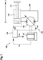
- an electrohydraulic system 100 as the invention may be based, is shown schematically.
- the electrohydraulic system 100 has an actuator designed as a hydraulic cylinder 110 with a piston 111 movable along an x-axis, which actuator is actuated by a variable-speed variable displacement pump 120.
- a hydraulic circuit 130 with, for example, oil as the medium or operating medium is arranged between the variable-speed variable displacement pump 120 and the hydraulic cylinder 110.
- the variable-speed variable displacement pump 120 has a variable-speed drive in the form of an electric motor 121 and a conveyor mechanism 122 and is in particular in the form of an axial piston pump with a swash plate design.
- a variable-speed drive in the form of an electric motor 121 and a conveyor mechanism 122 and is in particular in the form of an axial piston pump with a swash plate design.
- a control and / or regulating unit 140 is programmed to carry out a preferred embodiment of a method according to the invention and specifies a speed setpoint n soll and a swivel angle setpoint ⁇ soll as a setpoint for the parameter determining the displacement volume per work cycle.
- n ist and ⁇ ist are provided in each case. This can be done using conventional sensors, for example.
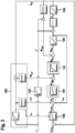
- a control loop according to a preferred embodiment of the invention or a method according to the invention is shown, as it can be implemented in a program in a control and / or regulating unit.
- a pressure p in a hydraulic circuit 130 such as that described in Figure 1 is shown, regulated to a target value p set.
- a speed setpoint to or 'to n (the difference between these target values are discussed later) to ⁇ 121 and a target value for a speed of the drive for a swivel angle than the the parameter determining the displacement volume per work cycle is determined or specified.
- These setpoint values for speed and swivel angle are then implemented accordingly in drive 121 or in conveyor mechanism 122.
- Drive 121 and swivel angle adjustment of the conveyor system 122 usually react to the setpoint specifications in accordance with a PT1 behavior with corresponding time constants T1 or T2.
- the controller 150 when the swivel angle or generally the displacement volume per cycle of the conveying mechanism, for example, is to be changed for reasons of efficiency, it is at the same time or in parallel, the first established by the controller 150 and predetermined speed reference value n 'to a function of a current speed 165 of an adjustment of the conveyor system and adjusted by means of a feedforward control so that the (adjusted) speed setpoint n setpoint is obtained, which is then used further.
- This takes place in particular within the framework of a model predictive control 160 with a corresponding model (often also referred to as “DigitalTwin”) for the variable displacement pump.
- a ratio or quotient of the maximum possible to the minimum possible swivel angle can be included in the determination of the adjusted speed setpoint, which in turn can depend on a current swivel angle, which here - through the model - is taken into account as an estimated value or calculated value ⁇ * is.
- an electronic swivel angle adjustment can be provided in which a magnetic force is generated by means of electricity, which counteracts a (mechanical) spring force in an adjusting cylinder.
- the rotational speed is adjusted at the same time as the swivel angle and there is no change in the pressure in the hydraulic circuit 130, so that no intervention by the (higher-level) controller 150 is necessary.
- the position x of the element or piston 111 according to, for example, is also the (superordinate) variable to be regulated Figure 1 can be used.
- FIG 3 a control loop according to a further preferred embodiment of the invention or a method according to the invention is shown, as it can be implemented in terms of programming in a control and / or regulating unit.
- a pressure p act is again exemplified in a hydraulic circuit 130, as it is, for example, in FIG Figure 1 is shown, regulated to a target value p set.
- a speed setpoint to n as a manipulated variable of a here likewise designed as a PI controller 150 controller.
- n from the speed command value is determined in consideration of a correction or pilot Terms .DELTA.n * (this will be discussed in), a speed error e n n by subtracting the actual speed is calculated and a speed controller 151 (implemented here as well as a PI controller) supplied to the outputs a setpoint torque M soll and acts on drive 121, which is again modeled with a PT1 behavior. This then results in an electrical drive torque M A of the pump 120.
- a swivel angle ⁇ is also specified as the parameter determining the displacement volume per work cycle for the conveyor mechanism 122, the swivel angle adjustment of which is again modeled with a PT1 behavior, from which the swivel angle (or a corresponding volume variable) ⁇ * results.
- an effective torque M eff of the pump 120 results, which acts on the speed.
- the hydraulic torque M hyd results, as above, as the product of the volume variable ⁇ * and the actual pressure, which can be weighted or increased if necessary via a P element.
- N is the product of the speed and the volume size ⁇ * results in a volume flow rate Q, which can be optionally weighted by a P-element or amplified, and then in the hydraulic circuit 130, taking into account compression factor and volume of the medium that is compressed , the corresponding actual pressure pist.
- the first established by the controller 150 and predetermined speed reference value is n parallel adjusted by way of a precontrol with the correction or precontrol term ⁇ n *.
- the pre-control term ⁇ n * is determined in particular in the context of a model predictive control 160 with a corresponding model (often also referred to as "DigitalTwin") for the variable displacement pump (whose swivel angle reaction to the swivel angle specification ⁇ is modeled with a PT1 behavior within block 160).
- the resultant modeled actual pivoting angle via a P-member is guided to the weighting or gain and is intended as an additive * n speed value .DELTA.n on the speed reference value, is applied.
- the modeled is actual swivel angle (or volume) multiplied performed with the actual pressure over a P-element and as an additive torque value M * hyd on the torque command value M should be switched on.
Landscapes
- Engineering & Computer Science (AREA)
- Mechanical Engineering (AREA)
- General Engineering & Computer Science (AREA)
- Physics & Mathematics (AREA)
- Fluid Mechanics (AREA)
- Computer Hardware Design (AREA)
- Control Of Positive-Displacement Pumps (AREA)
Applications Claiming Priority (1)
| Application Number | Priority Date | Filing Date | Title |
|---|---|---|---|
| DE102019220322.1A DE102019220322A1 (de) | 2019-12-20 | 2019-12-20 | Verfahren zum Betreiben einer drehzahlvariablen Verstellpumpe |
Publications (2)
| Publication Number | Publication Date |
|---|---|
| EP3839256A1 true EP3839256A1 (fr) | 2021-06-23 |
| EP3839256B1 EP3839256B1 (fr) | 2022-08-24 |
Family
ID=74141258
Family Applications (1)
| Application Number | Title | Priority Date | Filing Date |
|---|---|---|---|
| EP20213692.5A Active EP3839256B1 (fr) | 2019-12-20 | 2020-12-14 | Procédé de fonctionnement d'une pompe à débit variable à vitesse variable |
Country Status (3)
| Country | Link |
|---|---|
| EP (1) | EP3839256B1 (fr) |
| CN (1) | CN113007055B (fr) |
| DE (1) | DE102019220322A1 (fr) |
Families Citing this family (4)
| Publication number | Priority date | Publication date | Assignee | Title |
|---|---|---|---|---|
| DE102022203051B3 (de) | 2022-03-29 | 2023-10-12 | Robert Bosch Gesellschaft mit beschränkter Haftung | Verfahren zum Betreiben einer drehzahlvariablen Pumpe |
| CN114715800B (zh) * | 2022-04-19 | 2025-06-27 | 浙江三一装备有限公司 | 臂架角速度确定方法、装置、电子设备及存储介质 |
| DE102022205233B4 (de) | 2022-05-25 | 2023-12-07 | Robert Bosch Gesellschaft mit beschränkter Haftung | Verfahren zum Betreiben eines Elektrohydraulikaggregats |
| DE102022206540B3 (de) | 2022-06-28 | 2023-10-12 | Robert Bosch Gesellschaft mit beschränkter Haftung | Verfahren zur Regelung von drehzahlvariablen Fluidpumpen |
Citations (4)
| Publication number | Priority date | Publication date | Assignee | Title |
|---|---|---|---|---|
| DE102011119299A1 (de) * | 2011-11-24 | 2013-05-29 | Robert Bosch Gmbh | Verfahren zum Betreiben einerdrehzahlvariablen Verstellpumpe |
| DE102013006137A1 (de) * | 2013-04-10 | 2014-10-16 | Robert Bosch Gmbh | Regelung drehzahlvariabler Verstellpumpen mittels modellbasierter Optimierung |
| DE102014001981A1 (de) * | 2014-02-17 | 2015-08-20 | Robert Bosch Gmbh | Dynamischer Sollwertausgleich bei drehzahlvariablen Verstellpumpen |
| EP2192309B1 (fr) | 2008-11-29 | 2017-04-05 | Robert Bosch GmbH | Procédé et circuit de réglage destinés au réglage d'une alimentation en fluide sous pression pour un actionneur hydraulique |
Family Cites Families (1)
| Publication number | Priority date | Publication date | Assignee | Title |
|---|---|---|---|---|
| JP2816674B2 (ja) * | 1986-10-17 | 1998-10-27 | 株式会社小松製作所 | 油圧ポンプ制御装置 |
-
2019
- 2019-12-20 DE DE102019220322.1A patent/DE102019220322A1/de not_active Withdrawn
-
2020
- 2020-12-14 EP EP20213692.5A patent/EP3839256B1/fr active Active
- 2020-12-18 CN CN202011508905.1A patent/CN113007055B/zh active Active
Patent Citations (4)
| Publication number | Priority date | Publication date | Assignee | Title |
|---|---|---|---|---|
| EP2192309B1 (fr) | 2008-11-29 | 2017-04-05 | Robert Bosch GmbH | Procédé et circuit de réglage destinés au réglage d'une alimentation en fluide sous pression pour un actionneur hydraulique |
| DE102011119299A1 (de) * | 2011-11-24 | 2013-05-29 | Robert Bosch Gmbh | Verfahren zum Betreiben einerdrehzahlvariablen Verstellpumpe |
| DE102013006137A1 (de) * | 2013-04-10 | 2014-10-16 | Robert Bosch Gmbh | Regelung drehzahlvariabler Verstellpumpen mittels modellbasierter Optimierung |
| DE102014001981A1 (de) * | 2014-02-17 | 2015-08-20 | Robert Bosch Gmbh | Dynamischer Sollwertausgleich bei drehzahlvariablen Verstellpumpen |
Also Published As
| Publication number | Publication date |
|---|---|
| CN113007055A (zh) | 2021-06-22 |
| DE102019220322A1 (de) | 2021-06-24 |
| CN113007055B (zh) | 2025-08-05 |
| EP3839256B1 (fr) | 2022-08-24 |
Similar Documents
| Publication | Publication Date | Title |
|---|---|---|
| EP3839256B1 (fr) | Procédé de fonctionnement d'une pompe à débit variable à vitesse variable | |
| EP2121280B1 (fr) | Système de contrôle électrohydraulique | |
| DE102013006137A1 (de) | Regelung drehzahlvariabler Verstellpumpen mittels modellbasierter Optimierung | |
| AT515590B1 (de) | Dynamischer Sollwertausgleich bei drehzahlvariablen Verstellpumpen | |
| EP3748168B1 (fr) | Système d'entraînement hydraulique à deux pompes et à récupération d'énergie | |
| DE102019212845A1 (de) | Hydraulische Druckmittelversorgungsanordnung und Verfahren | |
| DE102017213650A1 (de) | Verfahren zum Regeln eines hydraulischen Systems, Regeleinheit für ein hydraulisches System und hydraulisches System | |
| EP3988801B1 (fr) | Procédé de fonctionnement d'un entraînement hydraulique | |
| WO2023156279A1 (fr) | Procédé de fonctionnement d'un ensemble hydraulique d'une machine de travail et machine de travail | |
| DE102021201895A1 (de) | Verfahren zum Betreiben einer drehzahlvariablen, elektrohydraulischen Pumpe, Recheneinheit und drehzahlvariable elektro-hydraulische Pumpe | |
| DE102023210960B3 (de) | Verfahren zum Betrieb einer Axialkolbenmaschine bei dem ein Nullfall berücksichtigt ist | |
| DE102021200693B4 (de) | Verfahren zur Modellparameteranpassung einer Axialkolbenpumpe | |
| EP3953771A1 (fr) | Unité de travail hydrostatique et procédé pour sa commande | |
| EP4402371B1 (fr) | Procédé pour un entraînement hydraulique, unité de commande, programme informatique et support d'enregistrement lisible par machine | |
| DE102015221684A1 (de) | Verfahren zum durcksensorlosen Stellen des Drucks eines mittels einer drehzahlgeregelten Pumpe geförderten Fluids | |
| DE102022206535A1 (de) | Verfahren zur Regelung von hydraulischen Komponenten | |
| DE102005025590A1 (de) | Regelvorrichtung sowie Verfahren zum Betrieb einer Regelvorrichtung | |
| DE102024112743A1 (de) | Bremskontrollvorrichtung | |
| EP4118334B1 (fr) | Dispositif de régulation d'une pompe hydraulique ou d'un moteur hydraulique | |
| EP2165062A1 (fr) | Procédé et dispositif pour contrôler le fonctionnement d'un régulateur de vitesse | |
| EP4253754B1 (fr) | Procédé de fonctionnement d'une pompe à vitesse variable | |
| DE102020213293A1 (de) | Verfahren zum Betreiben eines hydraulischen Antriebs | |
| AT522651A2 (de) | Verfahren und Regelschaltung zur Regelung einer Druckmittelzufuhr für einen hydraulischen Aktor | |
| DE102024202950A1 (de) | Verfahren zum Bestimmen eines Kalibrierungs-Steuerwerts für ein Steuerventil und Verfahren zum Kalibrieren eines Steuerventils | |
| DE102023134408A1 (de) | Hydraulische Axialkolbeneinheit und Verfahren zur Steuerung einer hydraulischen Axialkolbeneinheit |
Legal Events
| Date | Code | Title | Description |
|---|---|---|---|
| PUAI | Public reference made under article 153(3) epc to a published international application that has entered the european phase |
Free format text: ORIGINAL CODE: 0009012 |
|
| STAA | Information on the status of an ep patent application or granted ep patent |
Free format text: STATUS: THE APPLICATION HAS BEEN PUBLISHED |
|
| AK | Designated contracting states |
Kind code of ref document: A1 Designated state(s): AL AT BE BG CH CY CZ DE DK EE ES FI FR GB GR HR HU IE IS IT LI LT LU LV MC MK MT NL NO PL PT RO RS SE SI SK SM TR |
|
| STAA | Information on the status of an ep patent application or granted ep patent |
Free format text: STATUS: REQUEST FOR EXAMINATION WAS MADE |
|
| 17P | Request for examination filed |
Effective date: 20211223 |
|
| RBV | Designated contracting states (corrected) |
Designated state(s): AL AT BE BG CH CY CZ DE DK EE ES FI FR GB GR HR HU IE IS IT LI LT LU LV MC MK MT NL NO PL PT RO RS SE SI SK SM TR |
|
| RIC1 | Information provided on ipc code assigned before grant |
Ipc: F15B 11/042 20060101ALI20220330BHEP Ipc: F03C 1/26 20060101ALI20220330BHEP Ipc: F03C 1/06 20060101ALI20220330BHEP Ipc: F04B 49/06 20060101ALI20220330BHEP Ipc: F04B 49/20 20060101ALI20220330BHEP Ipc: F04B 1/26 20060101ALI20220330BHEP Ipc: F04B 1/324 20200101ALI20220330BHEP Ipc: F04B 1/32 20200101AFI20220330BHEP |
|
| GRAP | Despatch of communication of intention to grant a patent |
Free format text: ORIGINAL CODE: EPIDOSNIGR1 |
|
| STAA | Information on the status of an ep patent application or granted ep patent |
Free format text: STATUS: GRANT OF PATENT IS INTENDED |
|
| INTG | Intention to grant announced |
Effective date: 20220520 |
|
| GRAS | Grant fee paid |
Free format text: ORIGINAL CODE: EPIDOSNIGR3 |
|
| GRAA | (expected) grant |
Free format text: ORIGINAL CODE: 0009210 |
|
| STAA | Information on the status of an ep patent application or granted ep patent |
Free format text: STATUS: THE PATENT HAS BEEN GRANTED |
|
| AK | Designated contracting states |
Kind code of ref document: B1 Designated state(s): AL AT BE BG CH CY CZ DE DK EE ES FI FR GB GR HR HU IE IS IT LI LT LU LV MC MK MT NL NO PL PT RO RS SE SI SK SM TR |
|
| REG | Reference to a national code |
Ref country code: CH Ref legal event code: EP |
|
| REG | Reference to a national code |
Ref country code: IE Ref legal event code: FG4D Free format text: LANGUAGE OF EP DOCUMENT: GERMAN |
|
| REG | Reference to a national code |
Ref country code: AT Ref legal event code: REF Ref document number: 1513810 Country of ref document: AT Kind code of ref document: T Effective date: 20220915 Ref country code: DE Ref legal event code: R096 Ref document number: 502020001579 Country of ref document: DE |
|
| REG | Reference to a national code |
Ref country code: LT Ref legal event code: MG9D |
|
| REG | Reference to a national code |
Ref country code: NL Ref legal event code: MP Effective date: 20220824 |
|
| PG25 | Lapsed in a contracting state [announced via postgrant information from national office to epo] |
Ref country code: SE Free format text: LAPSE BECAUSE OF FAILURE TO SUBMIT A TRANSLATION OF THE DESCRIPTION OR TO PAY THE FEE WITHIN THE PRESCRIBED TIME-LIMIT Effective date: 20220824 Ref country code: RS Free format text: LAPSE BECAUSE OF FAILURE TO SUBMIT A TRANSLATION OF THE DESCRIPTION OR TO PAY THE FEE WITHIN THE PRESCRIBED TIME-LIMIT Effective date: 20220824 Ref country code: PT Free format text: LAPSE BECAUSE OF FAILURE TO SUBMIT A TRANSLATION OF THE DESCRIPTION OR TO PAY THE FEE WITHIN THE PRESCRIBED TIME-LIMIT Effective date: 20221226 Ref country code: NO Free format text: LAPSE BECAUSE OF FAILURE TO SUBMIT A TRANSLATION OF THE DESCRIPTION OR TO PAY THE FEE WITHIN THE PRESCRIBED TIME-LIMIT Effective date: 20221124 Ref country code: NL Free format text: LAPSE BECAUSE OF FAILURE TO SUBMIT A TRANSLATION OF THE DESCRIPTION OR TO PAY THE FEE WITHIN THE PRESCRIBED TIME-LIMIT Effective date: 20220824 Ref country code: LV Free format text: LAPSE BECAUSE OF FAILURE TO SUBMIT A TRANSLATION OF THE DESCRIPTION OR TO PAY THE FEE WITHIN THE PRESCRIBED TIME-LIMIT Effective date: 20220824 Ref country code: LT Free format text: LAPSE BECAUSE OF FAILURE TO SUBMIT A TRANSLATION OF THE DESCRIPTION OR TO PAY THE FEE WITHIN THE PRESCRIBED TIME-LIMIT Effective date: 20220824 Ref country code: FI Free format text: LAPSE BECAUSE OF FAILURE TO SUBMIT A TRANSLATION OF THE DESCRIPTION OR TO PAY THE FEE WITHIN THE PRESCRIBED TIME-LIMIT Effective date: 20220824 |
|
| PG25 | Lapsed in a contracting state [announced via postgrant information from national office to epo] |
Ref country code: PL Free format text: LAPSE BECAUSE OF FAILURE TO SUBMIT A TRANSLATION OF THE DESCRIPTION OR TO PAY THE FEE WITHIN THE PRESCRIBED TIME-LIMIT Effective date: 20220824 Ref country code: IS Free format text: LAPSE BECAUSE OF FAILURE TO SUBMIT A TRANSLATION OF THE DESCRIPTION OR TO PAY THE FEE WITHIN THE PRESCRIBED TIME-LIMIT Effective date: 20221224 Ref country code: HR Free format text: LAPSE BECAUSE OF FAILURE TO SUBMIT A TRANSLATION OF THE DESCRIPTION OR TO PAY THE FEE WITHIN THE PRESCRIBED TIME-LIMIT Effective date: 20220824 Ref country code: GR Free format text: LAPSE BECAUSE OF FAILURE TO SUBMIT A TRANSLATION OF THE DESCRIPTION OR TO PAY THE FEE WITHIN THE PRESCRIBED TIME-LIMIT Effective date: 20221125 |
|
| PG25 | Lapsed in a contracting state [announced via postgrant information from national office to epo] |
Ref country code: SM Free format text: LAPSE BECAUSE OF FAILURE TO SUBMIT A TRANSLATION OF THE DESCRIPTION OR TO PAY THE FEE WITHIN THE PRESCRIBED TIME-LIMIT Effective date: 20220824 Ref country code: RO Free format text: LAPSE BECAUSE OF FAILURE TO SUBMIT A TRANSLATION OF THE DESCRIPTION OR TO PAY THE FEE WITHIN THE PRESCRIBED TIME-LIMIT Effective date: 20220824 Ref country code: ES Free format text: LAPSE BECAUSE OF FAILURE TO SUBMIT A TRANSLATION OF THE DESCRIPTION OR TO PAY THE FEE WITHIN THE PRESCRIBED TIME-LIMIT Effective date: 20220824 Ref country code: DK Free format text: LAPSE BECAUSE OF FAILURE TO SUBMIT A TRANSLATION OF THE DESCRIPTION OR TO PAY THE FEE WITHIN THE PRESCRIBED TIME-LIMIT Effective date: 20220824 Ref country code: CZ Free format text: LAPSE BECAUSE OF FAILURE TO SUBMIT A TRANSLATION OF THE DESCRIPTION OR TO PAY THE FEE WITHIN THE PRESCRIBED TIME-LIMIT Effective date: 20220824 |
|
| REG | Reference to a national code |
Ref country code: DE Ref legal event code: R097 Ref document number: 502020001579 Country of ref document: DE |
|
| PG25 | Lapsed in a contracting state [announced via postgrant information from national office to epo] |
Ref country code: SK Free format text: LAPSE BECAUSE OF FAILURE TO SUBMIT A TRANSLATION OF THE DESCRIPTION OR TO PAY THE FEE WITHIN THE PRESCRIBED TIME-LIMIT Effective date: 20220824 Ref country code: EE Free format text: LAPSE BECAUSE OF FAILURE TO SUBMIT A TRANSLATION OF THE DESCRIPTION OR TO PAY THE FEE WITHIN THE PRESCRIBED TIME-LIMIT Effective date: 20220824 |
|
| P01 | Opt-out of the competence of the unified patent court (upc) registered |
Effective date: 20230509 |
|
| PG25 | Lapsed in a contracting state [announced via postgrant information from national office to epo] |
Ref country code: AL Free format text: LAPSE BECAUSE OF FAILURE TO SUBMIT A TRANSLATION OF THE DESCRIPTION OR TO PAY THE FEE WITHIN THE PRESCRIBED TIME-LIMIT Effective date: 20220824 |
|
| PLBE | No opposition filed within time limit |
Free format text: ORIGINAL CODE: 0009261 |
|
| STAA | Information on the status of an ep patent application or granted ep patent |
Free format text: STATUS: NO OPPOSITION FILED WITHIN TIME LIMIT |
|
| 26N | No opposition filed |
Effective date: 20230525 |
|
| REG | Reference to a national code |
Ref country code: BE Ref legal event code: MM Effective date: 20221231 |
|
| PG25 | Lapsed in a contracting state [announced via postgrant information from national office to epo] |
Ref country code: SI Free format text: LAPSE BECAUSE OF FAILURE TO SUBMIT A TRANSLATION OF THE DESCRIPTION OR TO PAY THE FEE WITHIN THE PRESCRIBED TIME-LIMIT Effective date: 20220824 Ref country code: LU Free format text: LAPSE BECAUSE OF NON-PAYMENT OF DUE FEES Effective date: 20221214 |
|
| PG25 | Lapsed in a contracting state [announced via postgrant information from national office to epo] |
Ref country code: IE Free format text: LAPSE BECAUSE OF NON-PAYMENT OF DUE FEES Effective date: 20221214 |
|
| PG25 | Lapsed in a contracting state [announced via postgrant information from national office to epo] |
Ref country code: FR Free format text: LAPSE BECAUSE OF NON-PAYMENT OF DUE FEES Effective date: 20221231 Ref country code: BE Free format text: LAPSE BECAUSE OF NON-PAYMENT OF DUE FEES Effective date: 20221231 |
|
| PG25 | Lapsed in a contracting state [announced via postgrant information from national office to epo] |
Ref country code: CY Free format text: LAPSE BECAUSE OF FAILURE TO SUBMIT A TRANSLATION OF THE DESCRIPTION OR TO PAY THE FEE WITHIN THE PRESCRIBED TIME-LIMIT Effective date: 20220824 |
|
| PG25 | Lapsed in a contracting state [announced via postgrant information from national office to epo] |
Ref country code: MK Free format text: LAPSE BECAUSE OF FAILURE TO SUBMIT A TRANSLATION OF THE DESCRIPTION OR TO PAY THE FEE WITHIN THE PRESCRIBED TIME-LIMIT Effective date: 20220824 |
|
| PG25 | Lapsed in a contracting state [announced via postgrant information from national office to epo] |
Ref country code: MC Free format text: LAPSE BECAUSE OF FAILURE TO SUBMIT A TRANSLATION OF THE DESCRIPTION OR TO PAY THE FEE WITHIN THE PRESCRIBED TIME-LIMIT Effective date: 20220824 |
|
| PG25 | Lapsed in a contracting state [announced via postgrant information from national office to epo] |
Ref country code: MC Free format text: LAPSE BECAUSE OF FAILURE TO SUBMIT A TRANSLATION OF THE DESCRIPTION OR TO PAY THE FEE WITHIN THE PRESCRIBED TIME-LIMIT Effective date: 20220824 |
|
| PG25 | Lapsed in a contracting state [announced via postgrant information from national office to epo] |
Ref country code: BG Free format text: LAPSE BECAUSE OF FAILURE TO SUBMIT A TRANSLATION OF THE DESCRIPTION OR TO PAY THE FEE WITHIN THE PRESCRIBED TIME-LIMIT Effective date: 20220824 |
|
| REG | Reference to a national code |
Ref country code: CH Ref legal event code: PL |
|
| PG25 | Lapsed in a contracting state [announced via postgrant information from national office to epo] |
Ref country code: MT Free format text: LAPSE BECAUSE OF FAILURE TO SUBMIT A TRANSLATION OF THE DESCRIPTION OR TO PAY THE FEE WITHIN THE PRESCRIBED TIME-LIMIT Effective date: 20220824 |
|
| PG25 | Lapsed in a contracting state [announced via postgrant information from national office to epo] |
Ref country code: CH Free format text: LAPSE BECAUSE OF NON-PAYMENT OF DUE FEES Effective date: 20231231 |
|
| PG25 | Lapsed in a contracting state [announced via postgrant information from national office to epo] |
Ref country code: CH Free format text: LAPSE BECAUSE OF NON-PAYMENT OF DUE FEES Effective date: 20231231 |
|
| PG25 | Lapsed in a contracting state [announced via postgrant information from national office to epo] |
Ref country code: HU Free format text: LAPSE BECAUSE OF FAILURE TO SUBMIT A TRANSLATION OF THE DESCRIPTION OR TO PAY THE FEE WITHIN THE PRESCRIBED TIME-LIMIT; INVALID AB INITIO Effective date: 20201214 |
|
| GBPC | Gb: european patent ceased through non-payment of renewal fee |
Effective date: 20241214 |
|
| PG25 | Lapsed in a contracting state [announced via postgrant information from national office to epo] |
Ref country code: GB Free format text: LAPSE BECAUSE OF NON-PAYMENT OF DUE FEES Effective date: 20241214 |
|
| PG25 | Lapsed in a contracting state [announced via postgrant information from national office to epo] |
Ref country code: TR Free format text: LAPSE BECAUSE OF FAILURE TO SUBMIT A TRANSLATION OF THE DESCRIPTION OR TO PAY THE FEE WITHIN THE PRESCRIBED TIME-LIMIT Effective date: 20220824 |
|
| PGFP | Annual fee paid to national office [announced via postgrant information from national office to epo] |
Ref country code: AT Payment date: 20251215 Year of fee payment: 6 |
|
| PGFP | Annual fee paid to national office [announced via postgrant information from national office to epo] |
Ref country code: DE Payment date: 20260223 Year of fee payment: 6 |
|
| PGFP | Annual fee paid to national office [announced via postgrant information from national office to epo] |
Ref country code: IT Payment date: 20251231 Year of fee payment: 6 |