EP3839408B1 - Unité de déclenchement pour une arme à feu - Google Patents
Unité de déclenchement pour une arme à feu Download PDFInfo
- Publication number
- EP3839408B1 EP3839408B1 EP19216895.3A EP19216895A EP3839408B1 EP 3839408 B1 EP3839408 B1 EP 3839408B1 EP 19216895 A EP19216895 A EP 19216895A EP 3839408 B1 EP3839408 B1 EP 3839408B1
- Authority
- EP
- European Patent Office
- Prior art keywords
- trigger
- sear
- axis
- hammer
- spring
- Prior art date
- Legal status (The legal status is an assumption and is not a legal conclusion. Google has not performed a legal analysis and makes no representation as to the accuracy of the status listed.)
- Active
Links
Images



Classifications
-
- F—MECHANICAL ENGINEERING; LIGHTING; HEATING; WEAPONS; BLASTING
- F41—WEAPONS
- F41A—FUNCTIONAL FEATURES OR DETAILS COMMON TO BOTH SMALLARMS AND ORDNANCE, e.g. CANNONS; MOUNTINGS FOR SMALLARMS OR ORDNANCE
- F41A11/00—Assembly or disassembly features; Modular concepts; Articulated or collapsible guns
-
- F—MECHANICAL ENGINEERING; LIGHTING; HEATING; WEAPONS; BLASTING
- F41—WEAPONS
- F41A—FUNCTIONAL FEATURES OR DETAILS COMMON TO BOTH SMALLARMS AND ORDNANCE, e.g. CANNONS; MOUNTINGS FOR SMALLARMS OR ORDNANCE
- F41A11/00—Assembly or disassembly features; Modular concepts; Articulated or collapsible guns
- F41A11/02—Modular concepts, e.g. weapon-family concepts
-
- F—MECHANICAL ENGINEERING; LIGHTING; HEATING; WEAPONS; BLASTING
- F41—WEAPONS
- F41A—FUNCTIONAL FEATURES OR DETAILS COMMON TO BOTH SMALLARMS AND ORDNANCE, e.g. CANNONS; MOUNTINGS FOR SMALLARMS OR ORDNANCE
- F41A17/00—Safety arrangements, e.g. safeties
- F41A17/46—Trigger safeties, i.e. means for preventing trigger movement
-
- F—MECHANICAL ENGINEERING; LIGHTING; HEATING; WEAPONS; BLASTING
- F41—WEAPONS
- F41A—FUNCTIONAL FEATURES OR DETAILS COMMON TO BOTH SMALLARMS AND ORDNANCE, e.g. CANNONS; MOUNTINGS FOR SMALLARMS OR ORDNANCE
- F41A17/00—Safety arrangements, e.g. safeties
- F41A17/74—Hammer safeties, i.e. means for preventing the hammer from hitting the cartridge or the firing pin
-
- F—MECHANICAL ENGINEERING; LIGHTING; HEATING; WEAPONS; BLASTING
- F41—WEAPONS
- F41A—FUNCTIONAL FEATURES OR DETAILS COMMON TO BOTH SMALLARMS AND ORDNANCE, e.g. CANNONS; MOUNTINGS FOR SMALLARMS OR ORDNANCE
- F41A19/00—Firing or trigger mechanisms; Cocking mechanisms
- F41A19/01—Counting means indicating the number of shots fired
- F41A19/02—Burst limiters
-
- F—MECHANICAL ENGINEERING; LIGHTING; HEATING; WEAPONS; BLASTING
- F41—WEAPONS
- F41A—FUNCTIONAL FEATURES OR DETAILS COMMON TO BOTH SMALLARMS AND ORDNANCE, e.g. CANNONS; MOUNTINGS FOR SMALLARMS OR ORDNANCE
- F41A19/00—Firing or trigger mechanisms; Cocking mechanisms
- F41A19/06—Mechanical firing mechanisms, e.g. counterrecoil firing, recoil actuated firing mechanisms
- F41A19/10—Triggers; Trigger mountings
-
- F—MECHANICAL ENGINEERING; LIGHTING; HEATING; WEAPONS; BLASTING
- F41—WEAPONS
- F41A—FUNCTIONAL FEATURES OR DETAILS COMMON TO BOTH SMALLARMS AND ORDNANCE, e.g. CANNONS; MOUNTINGS FOR SMALLARMS OR ORDNANCE
- F41A19/00—Firing or trigger mechanisms; Cocking mechanisms
- F41A19/06—Mechanical firing mechanisms, e.g. counterrecoil firing, recoil actuated firing mechanisms
- F41A19/14—Hammers, i.e. pivotably-mounted striker elements; Hammer mountings
-
- F—MECHANICAL ENGINEERING; LIGHTING; HEATING; WEAPONS; BLASTING
- F41—WEAPONS
- F41A—FUNCTIONAL FEATURES OR DETAILS COMMON TO BOTH SMALLARMS AND ORDNANCE, e.g. CANNONS; MOUNTINGS FOR SMALLARMS OR ORDNANCE
- F41A19/00—Firing or trigger mechanisms; Cocking mechanisms
- F41A19/06—Mechanical firing mechanisms, e.g. counterrecoil firing, recoil actuated firing mechanisms
- F41A19/15—Modular firing mechanism units
-
- F—MECHANICAL ENGINEERING; LIGHTING; HEATING; WEAPONS; BLASTING
- F41—WEAPONS
- F41A—FUNCTIONAL FEATURES OR DETAILS COMMON TO BOTH SMALLARMS AND ORDNANCE, e.g. CANNONS; MOUNTINGS FOR SMALLARMS OR ORDNANCE
- F41A19/00—Firing or trigger mechanisms; Cocking mechanisms
- F41A19/06—Mechanical firing mechanisms, e.g. counterrecoil firing, recoil actuated firing mechanisms
- F41A19/16—Adjustable firing mechanisms; Trigger mechanisms with adjustable trigger pull
-
- F—MECHANICAL ENGINEERING; LIGHTING; HEATING; WEAPONS; BLASTING
- F41—WEAPONS
- F41A—FUNCTIONAL FEATURES OR DETAILS COMMON TO BOTH SMALLARMS AND ORDNANCE, e.g. CANNONS; MOUNTINGS FOR SMALLARMS OR ORDNANCE
- F41A19/00—Firing or trigger mechanisms; Cocking mechanisms
- F41A19/06—Mechanical firing mechanisms, e.g. counterrecoil firing, recoil actuated firing mechanisms
- F41A19/42—Mechanical firing mechanisms, e.g. counterrecoil firing, recoil actuated firing mechanisms having at least one hammer
- F41A19/43—Mechanical firing mechanisms, e.g. counterrecoil firing, recoil actuated firing mechanisms having at least one hammer in bolt-action guns
- F41A19/44—Sear arrangements therefor
- F41A19/45—Sear arrangements therefor for catching the hammer after each shot, i.e. in single-shot or semi-automatic firing mode
Definitions
- the invention relates to a two-stage trigger unit, also called trigger device, which is suitable for handguns, especially for firearms of the rifle type M4/M16/AR15, according to the preamble of claim 1 and the US 2016/363401 A1
- the invention and its variants are not limited to rifles, carbines, etc., but can in principle also be used for pistols. The improvements and their effects/advantages are listed below.
- the US 2016/363401 A1 discloses a trigger system with hammer, which, as particularly from Fig. 7 As can be seen, both an interrupter and a locking element (sear) are housed in a recess in the trigger and arranged in a spring-loaded manner.
- the hammer and the trigger, both spring-loaded, can also be rotated in a common component using needle bearings.
- the various springs and components have to be housed in very confined spaces, and the strict geometric conditions that must be observed for the device to function are also problematic when it comes to maintenance and servicing in an armory using special tools.
- the invention primarily relates to such a trigger unit and only secondarily to a weapon with such a trigger unit.
- a modern trigger unit should generally be easy to operate, reliable, easy to maintain and adjustable between a "safe” and at least one “unlocked” state.
- a large number of such trigger units especially for AR15 type rifles, which are discussed here, have a design which prevents the selector from being adjusted to the "safe” position when the hammer is in the released position. This is often due to the fact that the trigger lever, comprising a selector (also often referred to as the safety lever), the blade and the release catch (usually referred to as the "sear” in English) which interacts with the hammer (also referred to as the striker). is designed as a single piece. Examples of this are the US 10,330,413 B2 , the EP 2 950 033 B1 , the US 7,600,338 B2 from which these relationships are very clearly evident.
- the object of the present invention is therefore to provide a trigger unit which enables the firearm to be secured when the hammer is knocked off.
- a further object of the invention is to provide a two-stage trigger unit with different trigger resistances.
- a further object of the invention is to provide a trigger unit as a "drop-in trigger unit" which is easy to handle, easy to maintain and relatively easy to replace.
- the locking element with its locking element axis and the trigger lever with its trigger axis form a common axis of rotation
- the locking element has a bearing recess on its upper side for receiving and limited rotation about a breaker axis of a breaker joint formed on the underside of the breaker, and wherein the bearing recess is designed to at least partially enclose the breaker joint in the direction of rotation about the breaker axis.
- the hammer which is mounted so that it can rotate around a hammer axis and can be pre-tensioned by means of a hammer spring, is no longer blocked by the trigger lever when it is fired.
- the trigger lever which is mounted so that it can rotate around the trigger axis, comprises an integrally formed tongue and a rear part of the trigger, which is designed to accommodate at least one interrupter.
- the design and arrangement according to the invention, or the interaction, of the locking element, The interrupter and trigger lever allow the selector to be adjusted in the off position up to the "safety" position, since the rear part of the trigger can be easily deflected in this state.
- the bearing recess and the interrupter joint are essentially designed to complement each other in terms of shape and size in order to allow rotation around the interrupter axis within limits. Assembly can be carried out relatively easily by pushing them together sideways, as explained in more detail in the description of the figures. This also ensures that the components of the trigger unit are not lost when installed.
- a trigger unit that is suitable for installation in a firearm is designated in its entirety with "2".
- the Fig. 1 shows a schematic exploded view in which a trigger unit 2, shown as a drop-in trigger unit, is shown before being inserted into a lower housing 1 of a rifle.
- a sliding piece 11 is shown, which in the rest position of the weapon, i.e. before firing, is mounted above the trigger unit 2 in an upper housing (not shown).
- a handle 12, a magazine holder 14 and a slide catch lever 15 can be seen on the lower housing 1 in the installed state.
- Fig. 1 a continuous fire group 5 and a selector 6 can be seen in an exploded view, which are not to be seen as part of the trigger unit 2 according to the invention, but are to be described for their function.
- the continuous fire group 5 comprises a continuous fire element 51 and a continuous fire spring 52 in the usual way, as well as a sleeve and a pin for fixing in the housing 1.
- the selector 6 in the form shown also comprises two actuating elements and a control shaft 61, whereby the control shaft 61 is arranged inside the housing 1 and can be adjusted in its angular position from the outside by the two actuating elements, i.e. by rotation about the transverse direction 92.
- the control shaft 61 has a geometry which interacts with different parts of the trigger unit 2 due to the formation of differently shaped cams along the control shaft 61, depending on the position of the selector 6.
- the control shaft 61 is essentially designed as can be seen from e.g. the DE 20 2011 004 556 U1 or the EP 2 950 033 B1 is evident.
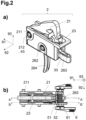
- Fig. 2a a assembled drop-in trigger unit can be seen in a perspective view, which is shown in the rest position.
- the trigger unit 2 according to the invention can theoretically also be installed without a trigger housing 23, i.e. directly in the lower housing 1, provided that smaller adaptations, such as a support for the locking element spring 41 in the housing 1, are provided.
- the illustrations show the preferred design as a drop-in trigger unit.
- Fig. 2b The rest position of the trigger unit 2 can be seen in a top view and in conjunction with Fig. 3 explained: A hammer 21, also often referred to as a striking piece, is mounted in the trigger housing 23, more precisely in a bearing sleeve 24, so that it can rotate around a hammer or striking piece axis 212.
- the interrupter 3, which is arranged inside the trigger lever 26, is also clearly visible.
- Fig. 2b Furthermore, the superimposed representation of the trigger unit 2 with the continuous fire group 5 and the selector 6 can be seen, as it corresponds to the installation situation and in conjunction with Fig. 1 becomes clear.
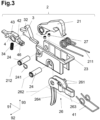
- the Fig. 3 shows a further exemplary representation of the trigger unit 2 in an exploded view, whereby the dashed lines are to be seen as reference lines to illustrate the position of the components in relation to one another in the installation situation.
- the representation clearly shows the multi-part nature of the trigger unit 2 according to the invention, whereby the trigger lever 26 in particular has no significant shape, i.e. no dedicated front section, in the running direction 91 to the front, as is very often seen in the prior art.
- the mechanical engagement on the hammer 21 or its release cam 215 does not take place directly with the trigger lever 26, but indirectly via a separately formed locking element 4.
- the locking element 4 and the trigger lever 26 have a common axis of rotation in the installed situation, which is accordingly referred to both as the trigger axis 262 and as the locking element axis 43.
- the locking element 4 is connected to an interrupter 3 according to the invention in such a way that the locking element 4 has a bearing recess 42 on its upper side for receiving and limited rotation of an interrupter joint 32 formed on the underside of the interrupter 3.
- a bearing recess 42 encloses the interrupter joint 32 at least partially in the direction of rotation about the interrupter axis 35, which runs in the transverse direction 92 through the interrupter joint 32.
- this allows a limited rotation of the interrupter about the interrupter axis 35 and by forming a common locking element axis 43 or trigger axis 262, the locking element 4 and the interrupter 3 are mounted individually and jointly so that they can be tilted or rotated within limits.
- the locking element 4 and the interrupter 3 are at least partially received laterally by the trigger lever 26.
- a locking element spring 41 is held on both sides of the trigger lever 26 by the bearing sleeve 24 in the trigger unit 2.
- the curved rear continuous leg of the locking element spring 41 engages in the illustrated embodiment, see also e.g. Fig. 5a , on the underside of the trigger housing 23.
- This type of spring support can also be achieved by a person skilled in the art in another way, such as by means of corresponding support points on the inside of the lower housing 1.
- the two loose ends of the locking element spring 41 are supported on the underside of the locking element 4 on locking element spring supports 412 provided for this purpose.
- a trigger edge 44 of the locking element 4 is pre-tensioned upwards, in the direction of the hammer 21.
- the hammer 21 is pre-tensioned in the installation situation by means of a corresponding hammer spring 211.
- the hammer spring 211 is tensioned in the usual way with the middle connecting piece from below against the hammer 21 and can be supported by the bearing sleeve 24, which holds the trigger lever 26.
- laterally projecting hammer spring supports 261 can be provided on the trigger lever 26, which act as abutments for the hammer spring 21 and thus prevent the hammer spring 21 from resting on the locking element spring 41.
- This connection is advantageous for the design of the inventive Trigger unit 2, since it transfers a force to be overcome to the trigger lever 26 and thus to the trigger 264, which is noticeable to the shooter, which is perceived as the first stage (often referred to as "1st stage") and defines the resistance in the idle pull, which will be explained later.
- FIG. 4a and 4b the locking lever 4 and the interrupter 3 are shown enlarged.
- the interrupter 3 has a hook 31 on the top, which interacts with the hammer hook 213.
- the interrupter 3 has a rear section 33, which in the transverse direction 92, as shown, can have a smaller extent than the middle or front section. This makes it easier to pick up/insert into the rear part of the trigger 263.
- the interrupter 3 can, as shown, have a type of support nose formed in the front section for guidance along the top of the locking element 4.
- the guidance and/or the support on the top of the locking element 4 can also be achieved by an alternative, functionally identical design of the pairing of bearing recess 42 and interrupter joint 32.
- the interrupter 3 has on its underside a interrupter joint 32 which serves to receive and rotatably mount on the upper side of the locking element 4 and which defines an interrupter axis 35 in the transverse direction 92. Furthermore, a receptacle for an interrupter spring 34 is formed on the underside of the interrupter 3. This in cross section e.g. in Fig. 5a The better visible receptacle is adapted in diameter and depth to the interrupter spring 34 in such a way that the latter is secured against slipping out sideways.
- the locking element 4 as shown in detail C in Fig. 4b shown enlarged, a spring recess 46.
- This spring recess 46 is formed on the upper side, i.e. facing the interrupter 3, and serves, like the receptacle in the interrupter 3, to at least partially accommodate and secure the interrupter spring 34 against loss.
- the spring recess 46 is partially open in at least one transverse direction 92, which facilitates assembly since the interrupter spring 34 does not have to be compressed so far in order to be able to be inserted into the recess or receptacle.
- a further aid during assembly is provided by a ramp 461 provided laterally in the area of the opening to the spring recess 46. Due to the rise of the ramp 461 in the direction of the spring recess 46, the interrupter spring 34 can be more easily inserted from the side, i.e. moved over it.
- the function of the interrupter spring 34 is the same, in that it pre-tensions the interrupter 3 about the interrupter axis 35, i.e. essentially upwards in the direction of the hammer hook 213.
- the bearing recess 42 is essentially designed to complement the shape and function of the interrupter joint 32, whereby in addition to the receptacle, a partial rotation of the interrupter 3, i.e. within defined limits, is possible.
- the assembly of the locking element 4 and the interrupter 3 is therefore carried out by sliding from one side in the transverse direction 92, whereby an independent disassembly or falling apart during operation is avoided by the lateral limitation within the trigger housing 23 or also the lower housing 1 of the firearm.
- the sectional views of the different rest and working positions of the Fig. 5a, 5c , 6a, 7a , 8a and 8b correspond to a side view through the median plane along the section line A-A', as exemplified for the rest position in Fig. 2b
- the sectional views of the different resting and working positions of the Fig. 5b, 5d , 6b and 7b correspond to a side view through the plane along the section line B-B', as exemplified for the resting position in Fig. 2b which essentially corresponds to a side view without the "left side wall" of the trigger housing 23.
- the rest position 71, the first trigger stage 72 (1st stage) and the second trigger stage 73 (2nd stage) are illustrated by dashed lines in the area of the trigger 264 and/or the rear part of the trigger 263.
- the hammer 21 is cocked, i.e. the hammer spring 211 tries to rotate the hammer head counterclockwise around the hammer axis 212 ( Fig. 2 ) and rests on the hammer spring supports 261.
- the hammer 21 has at least one release cam 215 on its outer surface in the area of the hammer axis 212, which is held in the rest position by a release edge 44 of the locking element 4.
- the release edge 44 is preloaded against the hammer 21 by the locking element spring 41 by engaging the locking element spring supports 412.
- the trigger lever 26 is preferably integrally formed as shown and has a tongue 264 that projects essentially downwards in the normal direction 93.
- the trigger lever 26 has a receiving opening in its central section and in the rear direction in the trigger rear part 263 for receiving the locking element 4 and the interrupter 3.
- Figs. 5a and 5b it can be clearly seen that the tongue 264 of the rest position 71 is pre-tensioned by the hammer spring 211, since the trigger lever 26 is pressed downwards. It can also be clearly seen that the selector 6 is in the "safe" position, with the control shaft 61 blocking the interrupter 3 on the rear section 33 at the top in a partial section and preventing upward deflection.
- a comparative analysis of the Figs. 5c and 5d shows that when a first force is applied to the trigger 264, a slight deflection to the rear is possible, whereby the rear part of the trigger 263 is rotated upwards until the trigger lever 26 on its inner surface 25 comes into contact with the underside of the locking element 4 in the contact area of the detail D.
- This slight free travel is also referred to as the free pull and can be clearly perceived by the shooter due to the retention force of the hammer spring 211 on the trigger lever 26.
- This first Trigger resistance is thus perceived between the rest position 71 and the end of the empty pull.
- the end of the empty pull is thus referred to as the first trigger stage 72, which in the Anglo-American language area is also often referred to as the "first stage".
- the first trigger stage 72 of this two-stage trigger unit 2 can, as in Figs. 5c and 5d
- the construction according to the invention also enables the same perception of the first trigger stage 72 when the firearm is unlocked, e.g. when the selector 6 is switched to the "single fire” or “continuous fire” position, as a comparison with the Figs. 6 and 7 shows.
- Figs. 5c and 5d the rest position 71 of the trigger 264 and the rear part of the trigger 263 are clearly visible in dashed lines. A further deflection of the trigger 264 beyond the first trigger stage 72 to the rear is prevented in the "safety" by the upper side of the rear part of the trigger 263 resting on both sides against correspondingly designed sections of the control shaft 61.
- FIG. 9 Detail D from Fig. 5a is enlarged in Fig. 9 shown.
- Particularly advantageous embodiments can be taken from this, which consist, for example, of a locking element extension 45 formed on the underside of the locking element 4.
- This allows a defined contact position between the inner surface 25 of the trigger lever 26 and the underside of the locking element 4, whereby the friction can be minimized and the reaching of the first trigger stage 72 can be perceived better.
- a further embodiment comprises the bevel of the inner surface 25 sloping backwards, as in Fig. 9
- This slanted surface can also advantageously influence the introduction of force between the rear part of the trigger 263 and the locking element extension 45 by essentially being at a right angle - provided the bevel is formed at the appropriate angle. This enables the trigger unit to be released very precisely and the first trigger stage 72 to be reached.
- an adjustable adjusting device 451 preferably designed as an adjusting screw (e.g. grub screw, worm screw) or also prismatic adjusting element 451, can function to adjust the part of the locking element extension 45 that protrudes on the underside.
- Fig. 11a and 11b Two prismatic adjustment elements 451 are shown as examples, which can be inserted laterally into a recess of the locking element 4 corresponding to the rough outer contour of the prism. Due to the differently rounded edges of the prismatic adjustment element 451, a locking element extension 45 can be formed by inserting it in the desired position, which protrudes to different extents from the locking element 4 on the underside, as can be seen from a comparison of the Figs. 11a and 11b clearly shows.
- the adjusting elements 451 are designed to be sufficiently wide in the transverse direction 92 to ensure stable mounting in the corresponding recess of the locking element 4.
- the prismatic adjusting elements 451 are exemplified as three-sided prisms, although four-, five-, or even multi-sided prisms are also conceivable in principle.
- a complementary, or alternative, possibility for fine adjustment would be to provide different trigger levers 26 with correspondingly adapted inner surfaces 25.
- Fig. 6 The situation is shown in which the selector 6 is set to the "single fire" position and the control shaft 61 with the corresponding sections enables a slight, further rotation of the trigger rear part 263 around the trigger axis 262. Due to the previously described Fig. 5 sufficiently described function of the trigger unit 2 until the first trigger stage 72 is reached, a second, usually higher, trigger resistance is thus perceived upon further deflection of the tongue 264 to the rear.
- This second trigger resistance results in part from the direct transmission of force from the trigger lever 26 to the locking element 4, since after contact of the locking element 4 with the inner surface 25, the latter rotates together around the Trigger axis 262 must be rotated.
- the hammer spring 211 still tries to press the trigger lever 26 downwards.
- the release edge 44 of the locking element 4 must be disengaged from the release cam 215 of the hammer 21.
- the rest position 71 and the first trigger stage 72 are indicated schematically as dashed lines on the trigger 264, before the second trigger stage 73 is reached by releasing the trigger edge 44 from the trigger cam 215.
- the continuous fire unit 5 is as in Fig. 5 still shown in its resting position.
- a further deflection of the trigger 264 to the rear, i.e. a further movement of the rear part of the trigger 263 upwards, is limited by the control shaft 61.
- the hammer 21 By releasing the hammer 21, it is rotated around the hammer axis 212 (see e.g. Fig. 8a ) and accelerated within the central recess of the slide 11 onto the firing pin.
- the interrupter 3 due to the pre-tension of the interrupter spring 34, attempts to rotate upwards around the interrupter axis 35, which is made possible at least within certain limits by the position of the selector 6, until the rear section 33 on the upper side contacts the corresponding section of the control shaft 61. This of course only applies in the case of the pulled trigger 264 - relieving the reins would again require the first trigger resistance etc. to be overcome again.
- the hammer 21 is thus caught by the interrupter 3 after each shot in "single fire".
- the tension on the interrupter 3 must first release the load on the tongue 264 so far forward that the trigger edge 44 is again positioned in front of the trigger cam 215.
- the hook 31 is disengaged from the hammer hook 213. At least the second trigger resistance must therefore be overcome to reach the second trigger stage 73.
- the pretension of the continuous fire spring 52 causes the continuous fire element 51 to briefly engage the continuous fire stop 214 of the hammer 21 when the slide 11 returns.
- the hammer 21 is held until the locking process is completed and the slide piece 11 strikes the underside of the continuous fire element 51, whereby the hammer 21 is automatically released again.
- the central task of the present invention is considered to be the possibility of moving the selector 6 to the "safety" position when the hammer 21 is in the "knocked off” position and thus the trigger unit 2 is not cocked.
- This situation is described in Fig. 8
- the hammer 21 is in the firing position, as can be the case with a fire arrester, i.e. a non-ignited cartridge.
- the selector 6 is shown in the "continuous fire position", whereby the situation is analogous to the "single fire position". Due to the inventive design of the trigger unit 2, i.e.
- the rear part of the trigger 263 can be moved downwards when the selector 6 is adjusted to the "safety" position, as shown in Fig. 8b
- the locking element 4 can be applied to the hammer 21 from below under pre-tension, without hindering it during a new loading process and immediately engaging the trigger cam 215 again.
- the continuous fire unit 5 can also be brought back into the rest position by adjusting the selector 6, without being influenced by the position of the struck hammer 21. This would be impossible with a one-piece trigger lever which would act "forward" directly on the hammer 21.
- the situation in Fig. 8b thus shows the selector 6 in the "safety” position, whereby the tongue 264 is deflected at least until the second trigger stage 72 is reached.
- a further embodiment of the invention relates to the design of the trigger edge 44, which has a special shape in the contact area with the trigger cam 215.
- An enlarged, albeit schematic, representation of the detail E from Fig. 5c shows the trigger edge 44, which preferably has an oblique and/or convex shape on the surface facing the trigger cam 215.
- a convex curvature of this surface enables the reduction of the contact surface between the trigger edge 44 and the trigger cam 215 to lead to a homogeneous increase in the second trigger resistance due to the essentially arcuate movement of the locking element 4 around the trigger axis 262 from the time the first trigger stage 71 is reached.
- the resulting increase in the surface pressure thus increases essentially linearly with the remaining contact surface, whereas with a trigger edge 44 with a rectangular design an inhomogeneous increase in the trigger resistance would occur.
- the trigger edge 44 has a convex curvature with a radius r 441, measured from the trigger axis 262 or locking element axis 43 to the apex of the curvature.
- This radius 441 is preferably smaller than the normal distance between the apex of the convex curvature and the locking element axis 43.
- the apex can also be set off-center from the trigger edge 44.
- the trigger unit 2 is primarily described as a drop-in trigger unit, wherein at least the hammer 21, the hammer spring 211, the interrupter 3, the interrupter spring 34, the locking element 4, the locking element spring 41, and the Trigger levers 26 according to the previously mentioned embodiments are arranged in a trigger housing 23 to form a drop-in trigger unit.
- clamping screws 27, such as in Fig. 2a shown, are intended for bracing the drop-in trigger unit. These clamping screws 27 are arranged to penetrate the trigger housing 23 on the underside and can be actuated from above, whereby the positional tolerance in the lower housing 1 of a firearm can be significantly reduced.
- the invention is not limited to the embodiment shown and described, but can be adapted and modified in various ways. This applies above all to the adaptation to other existing weapons, but also to the dimensions and geometry of the individual parts.
- the materials that can be used are the same as in the state of the art, and the same applies to the manufacturing processes.
Landscapes
- Engineering & Computer Science (AREA)
- General Engineering & Computer Science (AREA)
- Percussive Tools And Related Accessories (AREA)
- Toys (AREA)
- Aiming, Guidance, Guns With A Light Source, Armor, Camouflage, And Targets (AREA)
- Fats And Perfumes (AREA)
- Portable Nailing Machines And Staplers (AREA)
- Pivots And Pivotal Connections (AREA)
- Rotary Switch, Piano Key Switch, And Lever Switch (AREA)
- Electric Clocks (AREA)
Claims (14)
- Arme à feu, comprenant :- un boîtier inférieur (1) dans lequel sont prévus un sélecteur (6) et- une unité de détente (2), cette dernière présentant :- un chien (21) qui est monté tournant autour d'un axe de chien (212) et peut être mis sous précontrainte à l'aide d'un ressort de chien (211),- un levier de détente (26) qui est monté tournant autour d'un axe de détente (262) et comporte une queue de détente (264) qui est de préférence réalisée d'une seule pièce avec lui et qui, vu dans une direction normale (93), se situe sous l'axe de détente (262) et est déplacée en sens inverse d'un sens de canon, lors de l'actionnement de l'unité de détente, le levier de détente (26) présentant une partie arrière de détente (263) qui est réalisée en vue d'accueillir au moins un interrupteur (3),- un élément de verrouillage (4) monté tournant autour d'un axe d'élément de verrouillage (43) et pouvant être mis sous précontrainte à l'aide d'un ressort d'élément de précontrainte (41), l'axe de chien (212), l'axe de détente (262) et l'axe d'élément de verrouillage (43) étant disposés parallèlement les uns aux autres et parallèlement à une direction transversale (92),le sélecteur (6) libérant le mouvement de la partie arrière de détente (263) vers le haut, ou le bloquant, à l'aide d'un arbre de commande (61) rotatif, en fonction de la position angulaire de celui-ci,
caractérisée en ce quele levier de détente (26) présente une ouverture formant logement, et l'élément de verrouillage (4) est disposé au moins en partie dans l'ouverture formant logement,en ce que l'axe d'élément de verrouillage (43) et l'axe de détente (262) coïncident,en ce que l'élément de verrouillage (4) présente, sur sa face supérieure, un évidement de palier (42) destiné à accueillir une articulation d'interrupteur (32) réalisée sur la face inférieure de l'interrupteur (3) et à en permettre une rotation limitée autour d'un axe d'interrupteur (35), eten ce que l'évidement de palier (42) est réalisé de manière à entourer l'articulation d'interrupteur (32) au moins en partie dans le sens de la rotation autour de l'axe d'interrupteur (35). - Unité de détente (2), de préférence unité de détente Drop-In, qui comprend au moins un chien (21), un ressort de chien (211), un interrupteur (3), un ressort d'interrupteur (34), un élément de verrouillage (4), un ressort d'élément de verrouillage (41) ainsi qu'un levier de détente (26), le cas échéant dans un boîtier de détente (23), et qui est réalisée de manière à ce que qu'elle puisse être insérée avec un sélecteur (6) dans un boîtier inférieur (1) d'une arme à feu, sachant que :- le chien (21), qui est monté tournant autour d'un axe de chien (212), peut être mis sous précontrainte à l'aide d'un ressort de chien (211),- le levier de détente (26), qui est monté tournant autour d'un axe de détente (262), comporte une queue de détente (264) qui est de préférence réalisée d'une seule pièce avec lui et qui, vu dans une direction normale (93), se situe sous l'axe de détente (262) et est déplacée en sens inverse d'un sens de canon (91), lors de l'actionnement de l'unité de détente, le levier de détente (26) présentant une partie arrière de détente (263) qui est réalisée en vue d'accueillir au moins l'interrupteur (3),- l'élément de verrouillage (4) est monté tournant autour d'un axe d'élément de verrouillage (43) et peut être mis sous précontrainte à l'aide d'un ressort d'élément de verrouillage (41), l'axe de chien (212), l'axe de détente (262) et l'axe d'élément de verrouillage (43) étant disposés parallèlement les uns aux autres et parallèlement à une direction transversale (92),le sélecteur (6) libérant le mouvement de la partie arrière de détente (263) vers le haut ou le bloquant,
caractérisée en ce quele levier de détente (26) présente une ouverture formant logement, et l'élément de verrouillage (4) est disposé au moins en partie dans l'ouverture logement,en ce que l'élément de verrouillage (4) présente, sur sa face supérieure, un évidement de palier (42) destiné à accueillir une articulation d'interrupteur (32) réalisée sur la face inférieure de l'interrupteur (3) et à en permettre une rotation limitée autour d'un axe d'interrupteur (35), eten ce que l'évidement de palier (42) est réalisé de manière à entourer l'articulation d'interrupteur (32) au moins en partie dans le sens de la rotation autour de l'axe d'interrupteur (35). - Arme à feu selon la revendication 1 ou unité de détente (2), de préférence unité de détente Drop-In, selon la revendication 2, caractérisée en ce qu'une face intérieure (25) de la partie arrière de détente (263) qui est tournée vers l'élément de verrouillage (4) est réalisée en descendant vers l'arrière, de préférence sous forme de surface oblique.
- Arme à feu selon une des revendications 1 ou 3, ou unité de détente (2), de préférence unité de détente Drop-In, selon une des revendications 2 ou 3, caractérisée en ce que l'élément de verrouillage (4) présente une arête de déclenchement (44) dont la surface tournée vers une came de déclenchement (215) du chien (21) présente une forme convexe.
- Arme à feu ou unité de détente (2), de préférence unité de détente Drop-In, selon la revendication 4, caractérisée en ce que la surface convexe de l'arête de déclenchement (44) présente un rayon r (441) par rapport à l'axe de détente (262) ou l'axe d'élément de verrouillage (43) qui est compris dans la plage de 0,8 < r < 1,2, de préférence de 0,75 < r < 1,1.
- Arme à feu selon une des revendications 1 ou 3 à 5, ou unité de détente (2), de préférence unité de détente Drop-In, selon une des revendications 2 à 5, caractérisée en ce qu'il est prévu sur l'élément de verrouillage (4), sur les deux côtés dans le sens transversal (52), respectivement un appui de ressort d'élément de verrouillage (412) destiné à l'appui du ressort d'élément de verrouillage (41).
- Arme à feu selon une des revendications 1 ou 3 à 6, ou unité de détente (2), de préférence unité de détente Drop-In, selon une des revendications 2 à 6, comprenant un ressort de chien (211) avec une première et une deuxième branche, caractérisée en ce qu'il est prévu sur le levier de détente (26), sur les deux côtés dans le sens transversal (52), respectivement un appui de ressort de chien (261) destiné à l'appui du ressort de chien (211).
- Arme à feu selon une des revendications 1 ou 3 à 7, ou unité de détente (2), de préférence unité de détente Drop-In, selon une des revendications 2 à 7, caractérisée en ce que l'interrupteur (3) présente sur sa face inférieure un évidement destiné à accueillir au moins en partie un ressort d'interrupteur (34).
- Arme à feu selon une des revendications 1 ou 3 à 8, ou unité de détente (2), de préférence unité de détente Drop-In, selon une des revendications 2 à 8, caractérisée en ce que l'élément de verrouillage (4) présente, sur sa face tournée vers l'interrupteur (3), un évidement à ressort (46) destiné à accueillir au moins en partie le ressort d'interrupteur (34).
- Arme à feu ou unité de détente (2), de préférence unité de détente Drop-In, selon la revendication 9, caractérisée en ce que l'évidement à ressort (46) est ouvert au moins partiellement, latéralement dans au moins une direction transversale (52).
- Arme à feu ou unité de détente (2), de préférence unité de détente Drop-In, selon la revendication 10, caractérisée en ce que l'évidement à ressort (46) présente une rampe (461) descendant vers l' extérieur.
- Arme à feu selon une des revendications 1 ou 3 à 11, ou unité de détente (2), de préférence unité de détente Drop-In, selon une des revendications 2 à 11, caractérisée en ce qu'il est prévu sur l'élément de verrouillage (4), un dispositif d'ajustage (451) réglable, de préférence sous forme de vis sans tête ou d'élément d'ajustage prismatique, aux fins de réglage de la partie de la saillie d'un élément de verrouillage (45) avançant sur la face inférieure.
- Arme à feu selon une des revendications 1 ou 3 à 11, ou unité de détente (2), de préférence unité de détente Drop-In, selon une des revendications 2 à 11, caractérisée en ce qu'une saillie d'élément de verrouillage (45) est prévue sur la face inférieure de l'élément de verrouillage (4).
- Unité de détente (2) Drop-In selon une des revendications 2 à 13, caractérisée en ce qu'au moins une vis de serrage (27) est disposée de manière à traverser le boîtier de détente (23) sur la face inférieure.
Priority Applications (31)
| Application Number | Priority Date | Filing Date | Title |
|---|---|---|---|
| PL19216895.3T PL3839408T3 (pl) | 2019-12-17 | 2019-12-17 | Jednostka spustowa do broni palnej |
| ES19216895T ES3020232T3 (en) | 2019-12-17 | 2019-12-17 | Extraction unit for a firearm |
| EP19216895.3A EP3839408B1 (fr) | 2019-12-17 | 2019-12-17 | Unité de déclenchement pour une arme à feu |
| HRP20250399TT HRP20250399T1 (hr) | 2019-12-17 | 2019-12-17 | Okidač za vatreno oružje |
| CA3164062A CA3164062A1 (fr) | 2019-12-17 | 2020-10-13 | Detente d'arme a feu et arme a feu equipee de cette derniere |
| IL293674A IL293674B2 (en) | 2019-12-17 | 2020-10-13 | The trigger for a firearm and the firearm equipped with it |
| US17/757,346 US12215944B2 (en) | 2019-12-17 | 2020-10-13 | Trigger unit for a firearm and a firearm equipped therewith |
| PCT/EP2020/078723 WO2021121709A1 (fr) | 2019-12-17 | 2020-10-13 | Unité de déclenchement pour une arme à feu et arme à feu équipée de celle-ci |
| PCT/EP2020/078722 WO2021121708A1 (fr) | 2019-12-17 | 2020-10-13 | Détente d'arme à feu et arme à feu équipée de cette dernière |
| EP20789148.2A EP4078069B1 (fr) | 2019-12-17 | 2020-10-13 | Unité de déclenchement pour une arme à feu et arme à feu équipée de celle-ci |
| BR112022011146-0A BR112022011146B1 (pt) | 2019-12-17 | 2020-10-13 | Gatilho para uma arma de fogo e uma arma de fogo |
| PL20789148.2T PL4078069T3 (pl) | 2019-12-17 | 2020-10-13 | Jednostka spustowa broni palnej i broń palna wyposażona w taką jednostkę |
| HRP20250647TT HRP20250647T1 (hr) | 2019-12-17 | 2020-10-13 | Okidač za vatreno oružje i vatreno oružje opremljeno s njime |
| IL293673A IL293673B2 (en) | 2019-12-17 | 2020-10-13 | The trigger unit for a firearm and the firearm equipped with it |
| CA3164058A CA3164058A1 (fr) | 2019-12-17 | 2020-10-13 | Detente d'arme a feu et arme a feu equipee de cette derniere |
| BR112022011160-6A BR112022011160B1 (pt) | 2019-12-17 | 2020-10-13 | Unidade de gatilho para uma arma de fogo e uma arma de fogo |
| EP20808019.2A EP4078072A1 (fr) | 2019-12-17 | 2020-10-13 | Détente d'arme à feu et arme à feu équipée de cette dernière |
| EP20789149.0A EP4078071B1 (fr) | 2019-12-17 | 2020-10-13 | Module de détente pour une arme à feu et arme à feu équipée de cette dernière |
| US17/757,446 US11971233B2 (en) | 2019-12-17 | 2020-10-13 | Trigger for a firearm and a firearm equipped therewith |
| US17/757,388 US12264888B2 (en) | 2019-12-17 | 2020-10-13 | Trigger for a firearm and a firearm equipped therewith |
| BR112022011045-6A BR112022011045B1 (pt) | 2019-12-17 | 2020-10-13 | Gatilho para uma arma de fogo e uma arma de fogo |
| EP25154982.0A EP4545900A3 (fr) | 2019-12-17 | 2020-10-13 | Détente d'arme à feu et arme à feu équipée de cette dernière |
| PCT/EP2020/078724 WO2021121710A1 (fr) | 2019-12-17 | 2020-10-13 | Détente d'arme à feu et arme à feu équipée de cette dernière |
| ES20789148T ES3033550T3 (en) | 2019-12-17 | 2020-10-13 | Trigger unit for a firearm and a firearm equipped therewith |
| CA3164061A CA3164061A1 (fr) | 2019-12-17 | 2020-10-13 | Unite de declenchement pour une arme a feu et arme a feu equipee de celle-ci |
| IL293675A IL293675B2 (en) | 2019-12-17 | 2020-10-13 | The trigger for a firearm and the firearm equipped with it |
| US17/757,138 US11859930B2 (en) | 2019-12-17 | 2020-11-27 | Trigger unit for a firearm |
| BR112022011082-0A BR112022011082B1 (pt) | 2019-12-17 | 2020-11-27 | Unidade de disparo para uma arma de fogo |
| CA3163903A CA3163903A1 (fr) | 2019-12-17 | 2020-11-27 | Unite de detente pour une arme a feu |
| IL293576A IL293576B2 (en) | 2019-12-17 | 2020-11-27 | Firearm trigger unit |
| PCT/EP2020/083689 WO2021121908A1 (fr) | 2019-12-17 | 2020-11-27 | Unité de détente pour une arme à feu |
Applications Claiming Priority (1)
| Application Number | Priority Date | Filing Date | Title |
|---|---|---|---|
| EP19216895.3A EP3839408B1 (fr) | 2019-12-17 | 2019-12-17 | Unité de déclenchement pour une arme à feu |
Publications (3)
| Publication Number | Publication Date |
|---|---|
| EP3839408A1 EP3839408A1 (fr) | 2021-06-23 |
| EP3839408C0 EP3839408C0 (fr) | 2025-01-29 |
| EP3839408B1 true EP3839408B1 (fr) | 2025-01-29 |
Family
ID=68944169
Family Applications (5)
| Application Number | Title | Priority Date | Filing Date |
|---|---|---|---|
| EP19216895.3A Active EP3839408B1 (fr) | 2019-12-17 | 2019-12-17 | Unité de déclenchement pour une arme à feu |
| EP20789148.2A Active EP4078069B1 (fr) | 2019-12-17 | 2020-10-13 | Unité de déclenchement pour une arme à feu et arme à feu équipée de celle-ci |
| EP20808019.2A Withdrawn EP4078072A1 (fr) | 2019-12-17 | 2020-10-13 | Détente d'arme à feu et arme à feu équipée de cette dernière |
| EP25154982.0A Pending EP4545900A3 (fr) | 2019-12-17 | 2020-10-13 | Détente d'arme à feu et arme à feu équipée de cette dernière |
| EP20789149.0A Active EP4078071B1 (fr) | 2019-12-17 | 2020-10-13 | Module de détente pour une arme à feu et arme à feu équipée de cette dernière |
Family Applications After (4)
| Application Number | Title | Priority Date | Filing Date |
|---|---|---|---|
| EP20789148.2A Active EP4078069B1 (fr) | 2019-12-17 | 2020-10-13 | Unité de déclenchement pour une arme à feu et arme à feu équipée de celle-ci |
| EP20808019.2A Withdrawn EP4078072A1 (fr) | 2019-12-17 | 2020-10-13 | Détente d'arme à feu et arme à feu équipée de cette dernière |
| EP25154982.0A Pending EP4545900A3 (fr) | 2019-12-17 | 2020-10-13 | Détente d'arme à feu et arme à feu équipée de cette dernière |
| EP20789149.0A Active EP4078071B1 (fr) | 2019-12-17 | 2020-10-13 | Module de détente pour une arme à feu et arme à feu équipée de cette dernière |
Country Status (8)
| Country | Link |
|---|---|
| US (4) | US12215944B2 (fr) |
| EP (5) | EP3839408B1 (fr) |
| CA (4) | CA3164061A1 (fr) |
| ES (2) | ES3020232T3 (fr) |
| HR (2) | HRP20250399T1 (fr) |
| IL (4) | IL293674B2 (fr) |
| PL (2) | PL3839408T3 (fr) |
| WO (4) | WO2021121709A1 (fr) |
Families Citing this family (10)
| Publication number | Priority date | Publication date | Assignee | Title |
|---|---|---|---|---|
| US10837728B2 (en) * | 2018-02-20 | 2020-11-17 | Krl Holding Company, Inc. | Two-stage, drop-in trigger assembly |
| PL3839408T3 (pl) * | 2019-12-17 | 2025-05-26 | Glock Technology Gmbh | Jednostka spustowa do broni palnej |
| US11592255B2 (en) * | 2020-01-20 | 2023-02-28 | In Ovation Llc | Fire control assembly |
| US20230060494A1 (en) * | 2021-08-26 | 2023-03-02 | Street Smarts VR | Apparatus for adapting replica weapons to a virtual reality system |
| EP4194796B1 (fr) | 2021-12-10 | 2024-01-03 | Glock Technology GmbH | Fusil doté d'un dispositif de sécurité de fermeture |
| USD1038312S1 (en) * | 2022-02-04 | 2024-08-06 | Q, Llc | Trigger housing for a firearm |
| US12061058B2 (en) * | 2022-12-19 | 2024-08-13 | Jonathan Moore | Drop-in full automatic trigger groups |
| US12320600B2 (en) * | 2023-10-23 | 2025-06-03 | Gregory Vincent Gigliotti | Reduced friction, low profile trigger mechanism |
| DE102023135480B4 (de) | 2023-12-18 | 2025-08-28 | AKS GmbH | Abzugsvorrichtung mit Fangfunktion für ein Gewehr |
| US12410980B1 (en) * | 2024-10-25 | 2025-09-09 | Trigger Empire, Inc. | Drop-in system to enhance the resetting and operations of semiautomatic firearms |
Family Cites Families (68)
| Publication number | Priority date | Publication date | Assignee | Title |
|---|---|---|---|---|
| US774712A (en) * | 1903-10-20 | 1904-11-08 | Ole G Vold | Safety device for firearms. |
| US877665A (en) * | 1907-07-01 | 1908-01-28 | Floyd Sawyer | Evaporator. |
| GB1050054A (fr) * | 1964-09-28 | 1900-01-01 | ||
| FR1530296A (fr) | 1967-07-05 | 1968-06-21 | Sig Schweiz Industrieges | Dispositif propre à empêcher le rebondissement de la culasse mobile d'une arme à feu automatique |
| US3442173A (en) * | 1968-05-28 | 1969-05-06 | Us Army | Combined rifle and grenade launcher weapon selectively fired by a single trigger |
| DE3120128C1 (de) * | 1981-05-20 | 1982-12-09 | Heckler & Koch Gmbh, 7238 Oberndorf | Schusszahlbegrenzer fuer automatische Feuerwaffen mit Hahnschlagzuendung |
| US4893547A (en) * | 1981-12-31 | 1990-01-16 | Atchisson Maxwell G | Bolt mechanism for fire arm |
| US5251533A (en) * | 1992-06-08 | 1993-10-12 | Mark Layton | Firing mode selection apparatus |
| US5501134A (en) * | 1993-03-26 | 1996-03-26 | Charles R. Milazzo | Multi-stage match trigger assembly for use with semi-automatic weapons |
| US5623114A (en) * | 1995-03-03 | 1997-04-22 | Soper; Terry A. | Selectable fire trigger mechanism |
| DE19626077C2 (de) * | 1996-06-28 | 2000-10-26 | Heckler & Koch Gmbh | Abzugseinrichtung für eine Selbstladeschußwaffe mit Umstellung auf Dauerfeuer |
| US6131324A (en) * | 1998-11-30 | 2000-10-17 | Jewell; Arnold W. | Adjustable dual stage trigger assembly |
| US6223460B1 (en) | 1999-04-26 | 2001-05-01 | Fn Mfg Inc | Trigger safety |
| US6722072B1 (en) * | 2002-05-21 | 2004-04-20 | Mccormick Michael L. | Trigger group module for firearms and method for installing a trigger group in a firearm |
| US7421937B1 (en) * | 2004-03-05 | 2008-09-09 | John Gangl | Modular insertion trigger method and apparatus |
| US7654187B2 (en) * | 2004-04-30 | 2010-02-02 | Colt Defense Llc | Firearm fire control selector |
| US20070051236A1 (en) * | 2005-09-06 | 2007-03-08 | Colt Canada Corporation | Trigger mechanism for firearms with self-loading actions |
| DE102006048436B4 (de) * | 2006-08-03 | 2008-07-17 | Heckler & Koch Gmbh | Zweiwegeabzug mit Druckpunkt |
| US8677665B1 (en) | 2007-10-05 | 2014-03-25 | John F. Huber | Trigger assembly |
| US7600338B2 (en) | 2008-01-17 | 2009-10-13 | Geissele William H | Multi-stage trigger for automatic weapons |
| TWM360726U (en) * | 2009-03-12 | 2009-07-11 | Yih Kai Entpr Co Ltd | Improved trigger control device of toy guns |
| US8893607B2 (en) * | 2009-10-05 | 2014-11-25 | Colt's Manufacturing Company Llc | Trigger and hammer for automatic and semi-automatic rifles |
| US20110185615A1 (en) * | 2010-01-15 | 2011-08-04 | John Paul Gangl | Trigger insert system |
| US8549982B2 (en) * | 2010-12-10 | 2013-10-08 | Stephen P. Troy, Jr. | Firearm control devices |
| DE202011004556U1 (de) | 2011-03-30 | 2012-07-04 | Sig Sauer Gmbh | Abzugseinrichtung für eine Handfeuerwaffe |
| US8661722B2 (en) * | 2011-11-07 | 2014-03-04 | Megamet Solid Metals, Inc. | Firearm selector switch locking apparatus |
| US9863730B2 (en) * | 2013-09-22 | 2018-01-09 | Arthur J. Elftmann | Drop in trigger assembly |
| US20180202740A1 (en) * | 2014-09-21 | 2018-07-19 | Arthur J. Elftmann, JR. | Trigger Assembly with Modifications |
| US11629926B2 (en) * | 2012-01-28 | 2023-04-18 | Arthur J. Elftmann, JR. | Trigger assembly |
| US9857134B1 (en) * | 2013-05-07 | 2018-01-02 | Kimber Ip, Llc | Firearm sear safety |
| US9146067B2 (en) * | 2013-06-17 | 2015-09-29 | Michael A. Stakes | Trigger mechanism |
| US9057577B2 (en) | 2013-07-09 | 2015-06-16 | Karl E. Hannan | Rifle dry-fire apparatus and method |
| US9267750B1 (en) * | 2013-08-17 | 2016-02-23 | Superior Shooting Systems, Inc | Drop-in adjustable trigger assembly with camming safety linkage |
| US9046313B1 (en) * | 2013-12-04 | 2015-06-02 | O.F. Mossberg & Sons, Inc. | Adjustable modular trigger assembly for firearms |
| US9719744B2 (en) * | 2013-12-06 | 2017-08-01 | Robert Adam Horch | Fire control with multiple user-selectable trigger profiles |
| DE102014107620B3 (de) | 2014-05-30 | 2015-02-19 | Merkel Jagd- Und Sportwaffen Gmbh | Handfeuerwaffe und Abzugssicherung hierfür |
| US9605919B2 (en) * | 2014-07-06 | 2017-03-28 | David J. Wengender | Locking firearm safety |
| US9952012B2 (en) * | 2014-07-19 | 2018-04-24 | Franklin Armory Holdings, Inc. | Trigger group for semi-automatic firearms |
| US10006733B2 (en) * | 2014-10-22 | 2018-06-26 | In Ovation Llc | Non-fouling trigger |
| US20160161202A1 (en) * | 2014-12-06 | 2016-06-09 | Mark C. LaRue | Two-stage trigger mechanism for firearms |
| US9638485B2 (en) * | 2014-12-19 | 2017-05-02 | WHG Properties, LLC | Trigger mechanism for a firearm |
| US9671187B2 (en) * | 2015-03-25 | 2017-06-06 | Ronin B. Colman | Trigger module for automatic fire enabled firearms |
| US9618289B1 (en) * | 2015-09-29 | 2017-04-11 | WHG Properties, LLC | Trigger mechanism with momentary automatic safety |
| US10107580B2 (en) * | 2015-10-12 | 2018-10-23 | Franklin Armory Holdings, Inc. | Trigger group for semi-automatic firearms |
| US9952013B2 (en) * | 2015-11-03 | 2018-04-24 | Franklin Armory Holdings, Inc. | Trigger group for semi-automatic firearms |
| US9835398B2 (en) * | 2015-11-16 | 2017-12-05 | CMC Triggers Corp. | Firearm trigger group module with pivoting element non-coaxial to assembly pin and method of installing a trigger group module |
| US9869522B2 (en) * | 2015-12-10 | 2018-01-16 | Rock River Arms, Inc. | Firearm |
| US10330413B2 (en) | 2016-08-11 | 2019-06-25 | Springfield, Inc. | Half-cock trigger safety assembly |
| US10488136B2 (en) * | 2016-09-23 | 2019-11-26 | ArmWest, LLC | Selective fire firearm systems and methods |
| US10393459B2 (en) * | 2016-10-04 | 2019-08-27 | Edward Tompkins | Modular receiver system for firearms and an adjustable and tool-less removable trigger assembly |
| US10436535B1 (en) * | 2018-01-30 | 2019-10-08 | 22 Evolution Llc | Auto sear such as for use with any AR10 M16 or other midsize firearm platform |
| US10837728B2 (en) * | 2018-02-20 | 2020-11-17 | Krl Holding Company, Inc. | Two-stage, drop-in trigger assembly |
| US10488134B2 (en) | 2018-02-20 | 2019-11-26 | Krl Holding Company, Inc. | Two-stage, drop-in trigger assembly |
| US10731937B2 (en) * | 2018-06-04 | 2020-08-04 | Rable Machine, Inc. | Modular trigger assembly with retractable locking pins |
| US11085720B2 (en) * | 2018-07-25 | 2021-08-10 | Fortis Manufacturing, Inc. | Safety selector assembly and associated accessories |
| US10871340B2 (en) * | 2018-10-17 | 2020-12-22 | Franklin Armory Holdings, Inc. | Fire control group |
| US10871339B2 (en) * | 2018-12-06 | 2020-12-22 | Arthur J Elftmann, Jr. | Captive disconnector |
| US10670367B1 (en) * | 2019-04-11 | 2020-06-02 | Brent David Boyer | Ambidextrous safety selector for rifle |
| CN109974520B (zh) * | 2019-04-28 | 2024-04-12 | 重庆建设工业(集团)有限责任公司 | 一种击针平移式手枪的手动保险机构 |
| PL3839408T3 (pl) * | 2019-12-17 | 2025-05-26 | Glock Technology Gmbh | Jednostka spustowa do broni palnej |
| US11592255B2 (en) * | 2020-01-20 | 2023-02-28 | In Ovation Llc | Fire control assembly |
| US11609056B2 (en) * | 2020-06-29 | 2023-03-21 | Franklin Armory Holdings, Inc. | Selector for firearms |
| US11454471B1 (en) * | 2020-10-15 | 2022-09-27 | Kunvirt Firearms Inc. | Fire control lockout assembly for semiautomatic firearms providing single shot operation thereof |
| US20220214126A1 (en) * | 2021-01-07 | 2022-07-07 | 03312004 Llc | Trigger Travel Stop Limit |
| US11598599B2 (en) * | 2021-04-09 | 2023-03-07 | Polaris Capital Corporation | Firearm trigger |
| US11754360B2 (en) * | 2021-09-14 | 2023-09-12 | John Carnan Anderson | Trigger assembly group and methods of use |
| US20230132953A1 (en) * | 2022-01-10 | 2023-05-04 | Ethicon, Inc. | Plug for lung tissue tract sealing |
| US12163748B2 (en) * | 2022-04-26 | 2024-12-10 | Nathaniel J. Perle | Firearm assembly |
-
2019
- 2019-12-17 PL PL19216895.3T patent/PL3839408T3/pl unknown
- 2019-12-17 EP EP19216895.3A patent/EP3839408B1/fr active Active
- 2019-12-17 ES ES19216895T patent/ES3020232T3/es active Active
- 2019-12-17 HR HRP20250399TT patent/HRP20250399T1/hr unknown
-
2020
- 2020-10-13 IL IL293674A patent/IL293674B2/en unknown
- 2020-10-13 PL PL20789148.2T patent/PL4078069T3/pl unknown
- 2020-10-13 CA CA3164061A patent/CA3164061A1/fr active Pending
- 2020-10-13 EP EP20789148.2A patent/EP4078069B1/fr active Active
- 2020-10-13 IL IL293673A patent/IL293673B2/en unknown
- 2020-10-13 EP EP20808019.2A patent/EP4078072A1/fr not_active Withdrawn
- 2020-10-13 EP EP25154982.0A patent/EP4545900A3/fr active Pending
- 2020-10-13 HR HRP20250647TT patent/HRP20250647T1/hr unknown
- 2020-10-13 WO PCT/EP2020/078723 patent/WO2021121709A1/fr not_active Ceased
- 2020-10-13 WO PCT/EP2020/078724 patent/WO2021121710A1/fr not_active Ceased
- 2020-10-13 US US17/757,346 patent/US12215944B2/en active Active
- 2020-10-13 WO PCT/EP2020/078722 patent/WO2021121708A1/fr not_active Ceased
- 2020-10-13 CA CA3164062A patent/CA3164062A1/fr active Pending
- 2020-10-13 EP EP20789149.0A patent/EP4078071B1/fr active Active
- 2020-10-13 ES ES20789148T patent/ES3033550T3/es active Active
- 2020-10-13 US US17/757,388 patent/US12264888B2/en active Active
- 2020-10-13 US US17/757,446 patent/US11971233B2/en active Active
- 2020-10-13 CA CA3164058A patent/CA3164058A1/fr active Pending
- 2020-10-13 IL IL293675A patent/IL293675B2/en unknown
- 2020-11-27 CA CA3163903A patent/CA3163903A1/fr active Pending
- 2020-11-27 IL IL293576A patent/IL293576B2/en unknown
- 2020-11-27 WO PCT/EP2020/083689 patent/WO2021121908A1/fr not_active Ceased
- 2020-11-27 US US17/757,138 patent/US11859930B2/en active Active
Also Published As
Similar Documents
| Publication | Publication Date | Title |
|---|---|---|
| EP3839408A1 (fr) | Unité de déclenchement pour une arme à feu | |
| EP3835705B1 (fr) | Arrêtoir de culasse pour une arme à feu | |
| EP2047205A1 (fr) | Détente à deux voies | |
| EP0801284B1 (fr) | Configuration de levier de chargement | |
| EP4038337B1 (fr) | Unité canon pour arme à feu | |
| EP0666462A2 (fr) | Arma à feu portative comportant un verrou à coin pour verrouiller un tube de canon interchangeable | |
| EP4224106B1 (fr) | Arme à répétition | |
| DE202011102875U1 (de) | Aufkippmontage mit zusätzlichem Anschlag | |
| EP1500897B1 (fr) | Culasse pour arme à feu semi-automatique | |
| EP4224105B1 (fr) | Dispositif de détente d'une arme à feu portative | |
| EP4130640B1 (fr) | Tête de culasse pour une arme à feu | |
| EP4098967B1 (fr) | Dispositif gâchette pour une arme de poing | |
| EP4038333B1 (fr) | Carabine dotée d'une poignée de charge | |
| EP4028708B1 (fr) | Système de verrouillage | |
| EP4027099B1 (fr) | Unité de sélection de mode de feu pour une arme à feu | |
| EP4560250B1 (fr) | Ensemble de détente configuré pour être rapidement inséré et retiré du bas de caisse d'une arme à feu de type ar | |
| EP1559984A1 (fr) | Arme à feu de poing | |
| EP3690381B1 (fr) | Arme à feu à fonction de répétition | |
| DE202022100686U1 (de) | Repetiergewehr | |
| DE202022100685U1 (de) | Abzugseinrichtung einer Handfeuerwaffe | |
| DE202024100979U1 (de) | Vorrichtung zur Befestigung einer Zieleinrichtung an einer Schusswaffe | |
| DE2007066C3 (de) | Schlagbolzensicherungsvorrichtung für Feuerwaffen | |
| DE3743925C2 (fr) | ||
| DE102018120038A1 (de) | Handfeuerwaffe | |
| DE1903798A1 (de) | Gewehrschloss fuer Kipplaufwaffen |
Legal Events
| Date | Code | Title | Description |
|---|---|---|---|
| REG | Reference to a national code |
Ref country code: HR Ref legal event code: TUEP Ref document number: P20250399T Country of ref document: HR |
|
| PUAI | Public reference made under article 153(3) epc to a published international application that has entered the european phase |
Free format text: ORIGINAL CODE: 0009012 |
|
| STAA | Information on the status of an ep patent application or granted ep patent |
Free format text: STATUS: REQUEST FOR EXAMINATION WAS MADE |
|
| 17P | Request for examination filed |
Effective date: 20210222 |
|
| AK | Designated contracting states |
Kind code of ref document: A1 Designated state(s): AL AT BE BG CH CY CZ DE DK EE ES FI FR GB GR HR HU IE IS IT LI LT LU LV MC MK MT NL NO PL PT RO RS SE SI SK SM TR |
|
| STAA | Information on the status of an ep patent application or granted ep patent |
Free format text: STATUS: EXAMINATION IS IN PROGRESS |
|
| 17Q | First examination report despatched |
Effective date: 20230913 |
|
| GRAP | Despatch of communication of intention to grant a patent |
Free format text: ORIGINAL CODE: EPIDOSNIGR1 |
|
| STAA | Information on the status of an ep patent application or granted ep patent |
Free format text: STATUS: GRANT OF PATENT IS INTENDED |
|
| INTG | Intention to grant announced |
Effective date: 20240902 |
|
| GRAJ | Information related to disapproval of communication of intention to grant by the applicant or resumption of examination proceedings by the epo deleted |
Free format text: ORIGINAL CODE: EPIDOSDIGR1 |
|
| STAA | Information on the status of an ep patent application or granted ep patent |
Free format text: STATUS: EXAMINATION IS IN PROGRESS |
|
| GRAS | Grant fee paid |
Free format text: ORIGINAL CODE: EPIDOSNIGR3 |
|
| STAA | Information on the status of an ep patent application or granted ep patent |
Free format text: STATUS: GRANT OF PATENT IS INTENDED |
|
| GRAP | Despatch of communication of intention to grant a patent |
Free format text: ORIGINAL CODE: EPIDOSNIGR1 |
|
| GRAA | (expected) grant |
Free format text: ORIGINAL CODE: 0009210 |
|
| STAA | Information on the status of an ep patent application or granted ep patent |
Free format text: STATUS: THE PATENT HAS BEEN GRANTED |
|
| INTG | Intention to grant announced |
Effective date: 20241209 |
|
| AK | Designated contracting states |
Kind code of ref document: B1 Designated state(s): AL AT BE BG CH CY CZ DE DK EE ES FI FR GB GR HR HU IE IS IT LI LT LU LV MC MK MT NL NO PL PT RO RS SE SI SK SM TR |
|
| REG | Reference to a national code |
Ref country code: GB Ref legal event code: FG4D Free format text: NOT ENGLISH |
|
| REG | Reference to a national code |
Ref country code: CH Ref legal event code: EP |
|
| REG | Reference to a national code |
Ref country code: DE Ref legal event code: R096 Ref document number: 502019012877 Country of ref document: DE |
|
| REG | Reference to a national code |
Ref country code: IE Ref legal event code: FG4D Free format text: LANGUAGE OF EP DOCUMENT: GERMAN |
|
| U01 | Request for unitary effect filed |
Effective date: 20250224 |
|
| U07 | Unitary effect registered |
Designated state(s): AT BE BG DE DK EE FI FR IT LT LU LV MT NL PT RO SE SI Effective date: 20250303 |
|
| REG | Reference to a national code |
Ref country code: HR Ref legal event code: T1PR Ref document number: P20250399 Country of ref document: HR |
|
| REG | Reference to a national code |
Ref country code: ES Ref legal event code: FG2A Ref document number: 3020232 Country of ref document: ES Kind code of ref document: T3 Effective date: 20250522 |
|
| PG25 | Lapsed in a contracting state [announced via postgrant information from national office to epo] |
Ref country code: RS Free format text: LAPSE BECAUSE OF FAILURE TO SUBMIT A TRANSLATION OF THE DESCRIPTION OR TO PAY THE FEE WITHIN THE PRESCRIBED TIME-LIMIT Effective date: 20250429 |
|
| PG25 | Lapsed in a contracting state [announced via postgrant information from national office to epo] |
Ref country code: NO Free format text: LAPSE BECAUSE OF FAILURE TO SUBMIT A TRANSLATION OF THE DESCRIPTION OR TO PAY THE FEE WITHIN THE PRESCRIBED TIME-LIMIT Effective date: 20250429 Ref country code: IS Free format text: LAPSE BECAUSE OF FAILURE TO SUBMIT A TRANSLATION OF THE DESCRIPTION OR TO PAY THE FEE WITHIN THE PRESCRIBED TIME-LIMIT Effective date: 20250529 |
|
| PG25 | Lapsed in a contracting state [announced via postgrant information from national office to epo] |
Ref country code: GR Free format text: LAPSE BECAUSE OF FAILURE TO SUBMIT A TRANSLATION OF THE DESCRIPTION OR TO PAY THE FEE WITHIN THE PRESCRIBED TIME-LIMIT Effective date: 20250430 |
|
| PG25 | Lapsed in a contracting state [announced via postgrant information from national office to epo] |
Ref country code: SM Free format text: LAPSE BECAUSE OF FAILURE TO SUBMIT A TRANSLATION OF THE DESCRIPTION OR TO PAY THE FEE WITHIN THE PRESCRIBED TIME-LIMIT Effective date: 20250129 |
|
| PG25 | Lapsed in a contracting state [announced via postgrant information from national office to epo] |
Ref country code: SK Free format text: LAPSE BECAUSE OF FAILURE TO SUBMIT A TRANSLATION OF THE DESCRIPTION OR TO PAY THE FEE WITHIN THE PRESCRIBED TIME-LIMIT Effective date: 20250129 |
|
| PLBE | No opposition filed within time limit |
Free format text: ORIGINAL CODE: 0009261 |
|
| STAA | Information on the status of an ep patent application or granted ep patent |
Free format text: STATUS: NO OPPOSITION FILED WITHIN TIME LIMIT |
|
| REG | Reference to a national code |
Ref country code: CH Ref legal event code: L10 Free format text: ST27 STATUS EVENT CODE: U-0-0-L10-L00 (AS PROVIDED BY THE NATIONAL OFFICE) Effective date: 20251210 |
|
| REG | Reference to a national code |
Ref country code: CH Ref legal event code: U11 Free format text: ST27 STATUS EVENT CODE: U-0-0-U10-U11 (AS PROVIDED BY THE NATIONAL OFFICE) Effective date: 20260101 |
|
| REG | Reference to a national code |
Ref country code: HR Ref legal event code: ODRP Ref document number: P20250399 Country of ref document: HR Payment date: 20251203 Year of fee payment: 7 |
|
| 26N | No opposition filed |
Effective date: 20251030 |
|
| U20 | Renewal fee for the european patent with unitary effect paid |
Year of fee payment: 7 Effective date: 20251203 |
|
| PGFP | Annual fee paid to national office [announced via postgrant information from national office to epo] |
Ref country code: GB Payment date: 20251203 Year of fee payment: 7 |
|
| PGFP | Annual fee paid to national office [announced via postgrant information from national office to epo] |
Ref country code: HR Payment date: 20251203 Year of fee payment: 7 |
|
| PGFP | Annual fee paid to national office [announced via postgrant information from national office to epo] |
Ref country code: TR Payment date: 20251210 Year of fee payment: 7 |
|
| PGFP | Annual fee paid to national office [announced via postgrant information from national office to epo] |
Ref country code: CZ Payment date: 20251205 Year of fee payment: 7 |
|
| PGFP | Annual fee paid to national office [announced via postgrant information from national office to epo] |
Ref country code: PL Payment date: 20251204 Year of fee payment: 7 |
|
| PGFP | Annual fee paid to national office [announced via postgrant information from national office to epo] |
Ref country code: ES Payment date: 20260119 Year of fee payment: 7 |
|
| PGFP | Annual fee paid to national office [announced via postgrant information from national office to epo] |
Ref country code: CH Payment date: 20260101 Year of fee payment: 7 |