EP3839409A1 - Dispositif de détection et procédé de détection des facteurs d'interférence dans un canon d'arme ou dans un canon de chargement d'une arme à canon - Google Patents
Dispositif de détection et procédé de détection des facteurs d'interférence dans un canon d'arme ou dans un canon de chargement d'une arme à canon Download PDFInfo
- Publication number
- EP3839409A1 EP3839409A1 EP20208769.8A EP20208769A EP3839409A1 EP 3839409 A1 EP3839409 A1 EP 3839409A1 EP 20208769 A EP20208769 A EP 20208769A EP 3839409 A1 EP3839409 A1 EP 3839409A1
- Authority
- EP
- European Patent Office
- Prior art keywords
- pipe
- detection device
- emitter
- barrel
- sensor
- Prior art date
- Legal status (The legal status is an assumption and is not a legal conclusion. Google has not performed a legal analysis and makes no representation as to the accuracy of the status listed.)
- Pending
Links
Images
Classifications
-
- F—MECHANICAL ENGINEERING; LIGHTING; HEATING; WEAPONS; BLASTING
- F41—WEAPONS
- F41A—FUNCTIONAL FEATURES OR DETAILS COMMON TO BOTH SMALLARMS AND ORDNANCE, e.g. CANNONS; MOUNTINGS FOR SMALLARMS OR ORDNANCE
- F41A31/00—Testing arrangements
- F41A31/02—Testing arrangements for checking gun barrels
-
- G—PHYSICS
- G01—MEASURING; TESTING
- G01N—INVESTIGATING OR ANALYSING MATERIALS BY DETERMINING THEIR CHEMICAL OR PHYSICAL PROPERTIES
- G01N29/00—Investigating or analysing materials by the use of ultrasonic, sonic or infrasonic waves; Visualisation of the interior of objects by transmitting ultrasonic or sonic waves through the object
- G01N29/04—Analysing solids
- G01N29/07—Analysing solids by measuring propagation velocity or propagation time of acoustic waves
-
- G—PHYSICS
- G01—MEASURING; TESTING
- G01N—INVESTIGATING OR ANALYSING MATERIALS BY DETERMINING THEIR CHEMICAL OR PHYSICAL PROPERTIES
- G01N29/00—Investigating or analysing materials by the use of ultrasonic, sonic or infrasonic waves; Visualisation of the interior of objects by transmitting ultrasonic or sonic waves through the object
- G01N29/22—Details, e.g. general constructional or apparatus details
- G01N29/30—Arrangements for calibrating or comparing, e.g. with standard objects
-
- G—PHYSICS
- G01—MEASURING; TESTING
- G01N—INVESTIGATING OR ANALYSING MATERIALS BY DETERMINING THEIR CHEMICAL OR PHYSICAL PROPERTIES
- G01N21/00—Investigating or analysing materials by the use of optical means, i.e. using sub-millimetre waves, infrared, visible or ultraviolet light
- G01N21/84—Systems specially adapted for particular applications
- G01N21/88—Investigating the presence of flaws or contamination
- G01N21/95—Investigating the presence of flaws or contamination characterised by the material or shape of the object to be examined
- G01N21/954—Inspecting the inner surface of hollow bodies, e.g. bores
-
- G—PHYSICS
- G01—MEASURING; TESTING
- G01N—INVESTIGATING OR ANALYSING MATERIALS BY DETERMINING THEIR CHEMICAL OR PHYSICAL PROPERTIES
- G01N2291/00—Indexing codes associated with group G01N29/00
- G01N2291/10—Number of transducers
- G01N2291/105—Number of transducers two or more emitters, two or more receivers
-
- G—PHYSICS
- G01—MEASURING; TESTING
- G01N—INVESTIGATING OR ANALYSING MATERIALS BY DETERMINING THEIR CHEMICAL OR PHYSICAL PROPERTIES
- G01N2291/00—Indexing codes associated with group G01N29/00
- G01N2291/26—Scanned objects
- G01N2291/263—Surfaces
- G01N2291/2636—Surfaces cylindrical from inside
Definitions
- the invention relates to a detection device with the features of the preamble of claim 1 and a method with the features of the preamble of claim 12 for the detection of disruptive factors in a barrel designed as a weapon barrel or loading barrel of a barrel weapon.
- armed vehicles Due to the progressive automation of armed vehicles, it is necessary that the loading of a weapon, e.g. a tank, is automated. Reliability plays a major role here. It can happen that ammunition does not ignite or that parts of the ammunition remain in a gun barrel or a loading tube after a shot. A non-ignited ammunition is called a dud, parts of the ammunition are called ammunition fragments. If the next ammunition is loaded in such a case without removing the duds or ammunition fragments, this can lead to serious problems.
- armed vehicles were loaded by people. After exhausting gases, they had the opportunity to look into the pipe and examine them for possible disruptive factors such as the aforementioned duds or fragments. But even this turned out to be difficult, e.g. at night or with very small disruptive factors. If the disruptive factor is a defect in the pipe itself, such as a crack, breakout, other type of wear and tear or corrosion, this is difficult or impossible to see with the naked eye.
- a device for detecting the state of charge of a weapon barrel is known.
- Structure-borne sound waves are generated in the weapon barrel by a structure-borne sound wave exciter attached directly to the outside of the weapon barrel, and these structure-borne sound waves are then measured again with a structure-borne sound sensor.
- the structure-borne sound sensor is designed as a piezoelectric acceleration sensor.
- a processing unit evaluates the received data and compares them with reference values in order to detect a deviation from the normal state. This device is only used to detect the state of charge, that is to say to determine whether ammunition is present in the gun barrel or not. It is not used to determine other disruptive factors.
- sensors which are attached over the full length of the weapon barrel in order to detect the state in the weapon barrel over its full length.
- Piezoelectric sensors, Hall sensors, strain gauges, temperature sensors, pressure sensors and any combination of these can be used as sensors. These sensors are used in particular to monitor the shot. For example, the rate of fire, the rate of fire or vibrations of the weapon barrel are detected. With the help of the temperature and the total number of shots fired so far, conclusions can also be drawn about the wear. Necessary maintenance work can thus be initiated in good time.
- a detection method is known which is carried out with the aid of optical waveguides.
- These optical fibers are attached to two sides of the weapon barrel over a certain length of the weapon barrel.
- the primary purpose of the optical waveguides is to detect the inclination of the weapon barrel in order to enable the aim to be as precise as possible. If the weapon barrel is now bent or deformed, this can also be determined via the paths of the light within the optical waveguide and the aiming accuracy is further increased.
- the detection device should fit into the sequence of an automatic ammunition loading device without disturbing, delaying or completely preventing this sequence.
- a detection device with the features of claim 1 in that an emitter is arranged at an axial distance from a pipe end, the emitter having a radial distance to a longitudinal axis of a pipe which is greater than the radial distance of an inner wall of the Tube to its longitudinal axis, wherein a sensor is arranged at an axial distance from a tube end, wherein the sensor has a radial distance from a longitudinal axis of the tube which is greater as the radial distance between the inner wall of the pipe and its longitudinal axis, wherein measurement signals can be emitted into the pipe by means of the emitter and measurement signals reflected by means of the sensor can be received.
- the invention relates in particular to the arrangement of the detection device, in particular the components of the detection device relative to the pipe, and the design of the components.
- Such an arrangement of the detection device next to the barrel means that the detection device does not need to intervene in the weapon system.
- the pipe preferably has no structure-weakening fastening means for the detection device.
- the detection device can be used on different tube types or weapon systems. A particularly simple exchange of a defective pipe for another, faultless pipe is possible without changing the detection device. Furthermore, a particularly simple construction of the detection device is possible, since the design of the pipe plays a subordinate role.
- the measurement signals By emitting the measurement signals from the outside into the pipe, the measurement signals reach the areas to be checked directly, namely the interior of the pipe and the inner jacket of the pipe. This makes it particularly easy to evaluate the measurement signals, since the measurement signal is not influenced by other components.
- the gun barrel has two barrel ends, a barrel muzzle for dispensing the ammunition and a feed end for supplying the ammunition.
- the weapon system can have a separate loading tube for feeding the ammunition to the weapon barrel.
- the detection device can be used both for a weapon barrel and for a loading barrel.
- the longitudinal axis of the pipe is an imaginary straight line which has the same distance from the inner jacket of the pipe at every point.
- a holder has a frame, the frame delimiting an opening through which the ammunition can be guided or shot.
- the frame could, for example, be designed as an annular component with a circular opening.
- An angular design of the frame is also conceivable.
- the frame can be designed to be closed, so that there is a limited shape of the opening.
- An interruption of the frame is also conceivable.
- There is no limit to the geometric design of the frame The only important thing is that the ammunition can be fed past the frame and into the barrel. A particularly simple integration of the detection device into an automatic ammunition loading device is thus possible. A particularly fast and smooth transition between the detection of disruptive factors and the supply of ammunition is possible.
- two or more emitters are arranged on the holder.
- a particularly precise scanning of the interior and the inner jacket of the pipe is thus possible. Smaller disruptive factors can also be identified in this way. Furthermore, their characteristics and position can be determined very precisely.
- the superimposition of the measurement signals, which are emitted by the two or more emitters from different positions, is advantageous, since this allows different inner wall areas of the pipe to be covered.
- Two or more sensors are advantageously arranged on the holder. When using two or more sensors, a very comprehensive recording of the measurement signals reflected by the pipe is possible. The measurement signals arriving at the sensor are recorded by the sensor and converted into electrical signals. Due to the use of two or more sensors, the electrical signals provide an exact image of the interior and the inner jacket of the pipe, including any disruptive factors.
- Two or more emitters and / or two or more sensors are preferably arranged in a plane perpendicular to the longitudinal axis. Due to this arrangement, the emitters and / or the sensors have the same axial distances from a plane which is formed by the closest pipe end. Because of these equal distances, a particularly simple evaluation of all measurement signals is possible, since these are very similar to one another and can therefore be processed in a similar way. In addition, it makes sense to use the same distance for all sensors.
- Two or more emitters and / or two or more sensors are particularly preferably at the same distance from the longitudinal axis. This leads to a further simplification of the evaluation of the measurement signals. It also makes sense to use the same distance to the longitudinal axis for all emitters and / or sensors.
- the same distances are advantageously formed between adjacent emitters. Two emitters are adjacent to one another when their distance from one another is the smallest in contrast to the distances from the other emitters. This results in an even distribution of the emitters and the interior and the inner jacket of the tube are scanned evenly. This avoids creating blind spots in the interior and on the inner jacket of the pipe, which the measurement signals do not reach at all or with insufficient signal strength.
- sound waves can be emitted as measurement signals by means of the emitter.
- the emitter is designed as a sound wave emitter and the associated sensor as a sound wave sensor.
- laser beams can be emitted as measurement signals by means of the emitter.
- the emitter is designed as a laser and the associated sensor has an optical measuring principle.
- radar waves can be emitted as measurement signals by means of the emitter.
- the emitter is designed as a radar wave emitter and the associated sensor as a radar wave sensor.
- Sound wave emitters, radar wave emitters and lasers with corresponding sensors can be used in different combinations in order to be able to use the advantages of each measuring principle.
- the detection device preferably has a processing unit and a data connection, the processing unit being connected to the sensor with the aid of the data connection.
- the measurement signals are forwarded from the sensor to the processing unit.
- the processing unit is used to evaluate the measurement signals.
- the processing unit can be used to differentiate between a perfect condition of the pipe and a condition with one or more disruptive factors.
- the processing unit can be used to initiate various measures to deal with the disruptive factors, e.g. to eliminate them. This makes it possible to protect the pipe and adjacent components from major damage.
- an emitter is arranged at an axial distance from a pipe end, the emitter having a radial distance from a longitudinal axis of the pipe which is greater as the radial distance between an inner wall of the pipe and its longitudinal axis, measuring signals being emitted into the pipe by means of the emitter, a sensor being arranged at an axial distance from one pipe end, the sensor being at a radial distance from a longitudinal axis of the pipe, which is greater than the radial distance between the inner wall of the pipe and its longitudinal axis, with the measurement signals being received outside the pipe by means of the sensor.
- Such an arrangement of the detection device next to the barrel means that the detection device does not need to intervene in the weapon system.
- the pipe preferably has no structure-weakening fastening means for the detection device.
- the detection device can be used on different tube types or weapon systems. A particularly simple exchange of a defective pipe for another, faultless pipe is possible without changing the detection device. Furthermore, a particularly simple construction of the detection device is possible, since the design of the pipe plays a subordinate role.
- the measurement signals By emitting the measurement signals from the outside into the pipe, the measurement signals reach the areas to be checked directly, namely the interior of the pipe and the inner jacket of the pipe. This makes it particularly easy to evaluate the measurement signals, since the measurement signal is not influenced by other components.
- algorithms are executed in the processing unit in order to determine the position and / or the type of the interference factor.
- the received signals are compared with reference signals from a faultless pipe or specific interference factors.
- a special disruptive factor e.g. a defect in the pipe as a crack in the pipe, causes a special pattern in the measurement signal.
- the patterns are stored in the processing unit and are compared with the currently applied measurement signal. If they match, the type of interference factor and its position are known.
- Algorithms are advantageously executed in the processing unit in order to mask out parts of the measurement signal transmitted by the sensors which relate to non-relevant areas. This ensures that only relevant disruptive factors are detected. The risk of a source of interference being detected even though none is present is minimized. In addition, the effort required to detect the disruptive factors is reduced if only relevant areas are examined in detail.
- the detection of irrelevant areas can be carried out, for example, by evaluating the transit times between the emission of the measurement signal by the emitter and the reception of this measurement signal by the sensor. The interior of the pipe and its inner jacket are only scanned in a certain transit time range. Patterns stored in the processing unit can also be used to identify relevant areas.
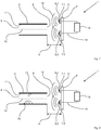
- Fig. 1 is schematically shown a side view of an embodiment of the detection device 1 according to the invention with a tube in section.
- the barrel is designed as a weapon barrel 2.
- the tube could also be designed as a loading tube of a barrel weapon.
- the weapon barrel 2 has a cylindrical inner wall 11, the nature of which has an important influence on the function of the barrel weapon.
- the weapon barrel 2 has two tube ends, one end being designed as a barrel muzzle 8 through which ammunition 15 leaves the weapon barrel 2 when a shot is fired.
- the second tube end is designed as a feed end 9, through which new ammunition 15 can be fed.
- the weapon barrel 2 has a longitudinal axis 10, which is the axis of symmetry of the weapon barrel 2.
- Three emitters 6.1 to 6.3 and three sensors 7.1 to 7.3 are arranged on the holder 3.
- the three emitters 6.1 to 6.3 and the three sensors 7.1 to 7.3 are preferably attached to the holder 3 by conventional means, for example by means of a screw or plug connection.
- the emitter 6.1 is combined with the sensor 7.1 associated with it to form a common structural unit.
- Emitter 6.2 and sensor 7.2 as well as emitter 6.3 and sensor 7.3 each also form a structural unit.
- the emitters 6.1 to 6.3 send measurement signals 12 in the form of sound waves into the interior of the weapon barrel 2. This interior is delimited by the inner wall 11, the barrel muzzle 8 and the feed end 9.
- the measurement signal 12 can be clearly and unambiguously identified with the aid of appropriate algorithms.
- a measurement process lasts as long as the sound waves need to get from the emitters 6.1 to 6.3 to the opposite pipe end, in the arrangement shown here, the feed end 9, and back again to the sensors 7.1 to 7.3.
- the weapon ear 2 is in perfect condition, so that the emitted sound waves are not reflected at any point.
- the measurement signals 12 detected by the sensors 7.1 to 7.3 are forwarded to a processing unit 13 via a data connection 14.
- Algorithms for analyzing the measurement signals 12 are executed in the processing unit 13.
- the incoming measurement signals 12 are compared with reference signals in order to avoid any interference factors or as in the in Fig. 1 the case shown to identify a flawless weapon barrel 2.
- the information that the weapon barrel 2 has no disruptive factors is thus present in the processing unit 13.
- This information is used, for example, by an automatic ammunition loading device (not shown here) to supply new ammunition 15.
- the detection device 1 according to the invention is of great importance for the proper functioning of such an automatic device Ammunition loading device. Further possible uses of the information generated by means of the detection device 1 are conceivable.
- the detection device 1 could also be arranged on the opposite side of the weapon barrel 2 at corresponding distances from the feed end 9.
- FIG. 2 is a schematic side view of the embodiment of the detection device 1 according to the invention with a pipe with interfering factors shown in section. It will be in Fig. 2 the same reference numerals as in Fig. 1 used. There Fig. 2 essentially with Fig. 1 is identical, reference is made here to the description Fig. 1 referenced and only discussed the differences. In contrast to Fig. 1 has the weapon barrel 2 in Fig. 2 two disruptive factors. These are an ammunition fragment 16 and a crack 17 in the inner wall 11. The measurement signals 12 emitted by the emitters 6.1 to 6.3 are reflected by this ammunition fragment 16 and the crack 17, which is symbolized by three lines in the figure, which represent the wavefronts of the Symbolize measurement signal 12.
- the reflections of the measurement signals 12 strike the sensors 7.1 to 7.3.
- This information is forwarded to the processing unit 13.
- the location of the interference factor is deduced from the time between the emission of the measurement signal 12 and the detection of a reflection in particular.
- the reflection from the crack 17 hits the sensors 7.1 to 7.3 earlier than the reflection from the ammunition fragment 16, since the sound bridges a smaller path difference overall. Due to the use of three sensors 7.1 to 7.3 and three emitters 6.1 to 6.3, a more precise three-dimensional image of the interior of the weapon barrel 2 including the disruptive factors can be generated.
- the measuring range of the detection device 1 can be focused on the interior of the weapon barrel 2 by so-called beam shaping. Any sources of interference outside the pipe are masked out.
- the areas in front of and behind the weapon barrel 2 can still be hidden. Reflections that arrive at the sensors 7.1 to 7.3 before a reflection of the barrel muzzle 8 or after a possible reflection at the level of the feed end 9 are not relevant with regard to the state of the weapon barrel 2.
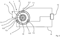
- Fig. 3 is a schematic plan view of the embodiment of the detection device 1 according to the invention with a tube shown in section. The viewing direction goes from the pipe to the detection device 1.
- the same reference numbers are used as in Figs. 1 and 2 used. In the following, the differences from the preceding figures are discussed in particular, and reference is made to the description of the preceding figures for the same components.
- Fig. 3 an ammunition 15 is also shown in section, which is located in the weapon barrel 2 after a loading process, for example.
- both the ammunition 15 and the weapon barrel 2 form a circle.
- the center of the circle, which is formed by the weapon barrel 2 is part of the longitudinal axis 10 of the weapon barrel 2.
- the design of the holder 3 and the arrangement of the emitter 6.1 are particularly good. to 6.3 and sensors 7.1 to 7.3 can be seen on this holder 3.
- the holder 3 has an annular frame 4.
- the unit comprising emitter 6.1 and sensor 7.1 has a radial distance e from the longitudinal axis 10 of the weapon barrel 2. This radial distance e is greater than the radius of the inner wall 11 of the weapon barrel 2.
- the emitters 6.2 and 6.3 and the sensors 7.2 and 7.3 also have the radial distance e from the longitudinal axis 10. This ensures that the ammunition 15 can be guided in the direction of the longitudinal axis 10 through the detection device 1 into the weapon barrel 2 or can be fired out of the weapon barrel 2.
- the ammunition 15 passes through an opening 5 of the detection device 1, which is formed by the above-described arrangement of the components of the detection device 1.
- the individual structural units made up of emitter 6.1 and sensor 7.1, emitter 6.2 and sensor 7.2 and emitter 6.3 and sensor 7.3 each have the same distance from one another and thus form an equilateral triangle.
- the design of the frame 4 is variable within the meaning of the invention, it is only important that the opening 5 produced is large enough to allow the ammunition 15 to pass.
- the arrangement of the emitters 6.1 shown here. up to 6.3 and sensors 7.1 to 7.3 in a plane perpendicular to the longitudinal axis 10, with the same distances e from the longitudinal axis 10 and with the same distances between the three structural units formed, has advantages in the evaluation of the measurement signals 12 in the processing unit 13. Because of this uniformity arises a particularly pronounced and thus easily recognizable pattern in the case of measurement signals 12 reflected by interference factors.
- the algorithms executed in the processing unit 13 can, due to this symmetrical arrangement of the emitters 6.1. up to 6.3 and sensors 7.1 to 7.3 are designed to be particularly simple without having to accept losses in terms of measurement accuracy.
- the emitters 6.1. up to 6.3 emit laser beams or radar waves and the sensors 7.1 to 7.3 detected laser beams or radar waves accordingly. Appropriate components are used for this.
- the evaluation of the measurement signals 12 in the processing unit 13 then takes place with the aid of adapted algorithms in a manner analogous to the evaluation of the measurement signals 12 of the sound waves described above.
- the detection device 1 is used in particular in an automatic ammunition feed device for a barrel weapon in armored vehicles.
- the information generated in the detection device 1 With the help of the information generated in the detection device 1, malfunctions of the ammunition feed device and the weapon barrel 2 can be effectively avoided. Disruptive factors can be eliminated quickly in order to be able to switch to the desired operation afterwards.
- the information can be used as the basis for a comprehensive maintenance system for the gun.
- the detection device 1 according to the invention can of course also be used for any type of barrel weapon independently of an automatic ammunition loading device.
Landscapes
- Physics & Mathematics (AREA)
- Health & Medical Sciences (AREA)
- Life Sciences & Earth Sciences (AREA)
- Chemical & Material Sciences (AREA)
- Analytical Chemistry (AREA)
- Biochemistry (AREA)
- General Health & Medical Sciences (AREA)
- General Physics & Mathematics (AREA)
- Immunology (AREA)
- Pathology (AREA)
- Engineering & Computer Science (AREA)
- General Engineering & Computer Science (AREA)
- Acoustics & Sound (AREA)
- Length Measuring Devices With Unspecified Measuring Means (AREA)
- Length Measuring Devices Characterised By Use Of Acoustic Means (AREA)
Applications Claiming Priority (1)
| Application Number | Priority Date | Filing Date | Title |
|---|---|---|---|
| DE102019134884.6A DE102019134884A1 (de) | 2019-12-18 | 2019-12-18 | Detektionsvorrichtung und Verfahren zur Detektion von Störfaktoren in einem Waffenrohr oder Laderohr einer Rohrwaffe |
Publications (1)
| Publication Number | Publication Date |
|---|---|
| EP3839409A1 true EP3839409A1 (fr) | 2021-06-23 |
Family
ID=73497698
Family Applications (1)
| Application Number | Title | Priority Date | Filing Date |
|---|---|---|---|
| EP20208769.8A Pending EP3839409A1 (fr) | 2019-12-18 | 2020-11-19 | Dispositif de détection et procédé de détection des facteurs d'interférence dans un canon d'arme ou dans un canon de chargement d'une arme à canon |
Country Status (2)
| Country | Link |
|---|---|
| EP (1) | EP3839409A1 (fr) |
| DE (1) | DE102019134884A1 (fr) |
Citations (8)
| Publication number | Priority date | Publication date | Assignee | Title |
|---|---|---|---|---|
| US4315688A (en) * | 1979-08-08 | 1982-02-16 | Diffracto Ltd. | Electro-optical sensor systems for thread and hole inspection |
| US5825948A (en) | 1997-07-08 | 1998-10-20 | Sirkis; James S. | Fiber optic sensor for spatially separated elements in a system |
| DE19737078A1 (de) | 1997-08-26 | 1999-03-18 | Rheinmetall Ind Ag | Vorrichtung zur Überwachung des Ladezustandes einer Rohrwaffe |
| US5963042A (en) * | 1994-12-16 | 1999-10-05 | Tokyo Gas Co., Ltd. | Method for inspecting the elements of piping systems by electromagnetic waves |
| EP2023128A1 (fr) * | 2006-05-23 | 2009-02-11 | Kirin Techno-System Company, Limited | Structure de support de tête d'inspection dans un appareil d'inspection de surface, et appareil d'inspection de surface |
| WO2010005399A2 (fr) * | 2008-07-10 | 2010-01-14 | Visionxtreme Pte. Ltd. | Procédé et appareil d’inspection de trou |
| KR20160001107A (ko) * | 2014-06-26 | 2016-01-06 | (주)유알시스 | 내면검사장치 |
| US20190011208A1 (en) | 2017-01-13 | 2019-01-10 | Wilcox Industries Corp. | Sensor system for advanced smart weapons barrels |
Family Cites Families (6)
| Publication number | Priority date | Publication date | Assignee | Title |
|---|---|---|---|---|
| AT389764B (de) * | 1988-03-04 | 1990-01-25 | Avl Verbrennungskraft Messtech | Verfahren und einrichtung zur bestimmung innenballistischer kenngroessen in rohrwaffen |
| DE4446235A1 (de) * | 1994-12-23 | 1996-06-27 | Mauser Werke Oberndorf Waffensysteme Gmbh | Meßgerät für ein Rohr, insbesondere Waffenrohr |
| US9310321B1 (en) * | 2010-03-26 | 2016-04-12 | The United States Of America As Represented By The Secretary Of The Army | System and method for conducting electromagnetic resonant cavity inspection of gun barrels |
| ITBS20120044A1 (it) * | 2012-03-27 | 2013-09-28 | Beretta Armi Spa | Arma da fuoco con dispositivo di verifica dello stato della canna |
| US9316759B2 (en) * | 2013-05-06 | 2016-04-19 | Kenneth J Hintz | Cavity anomaly detection device |
| EP2894429B1 (fr) * | 2014-01-08 | 2018-08-15 | Nostromo Holdings, LLC | Dispositif de sécurité de mortier |
-
2019
- 2019-12-18 DE DE102019134884.6A patent/DE102019134884A1/de active Pending
-
2020
- 2020-11-19 EP EP20208769.8A patent/EP3839409A1/fr active Pending
Patent Citations (8)
| Publication number | Priority date | Publication date | Assignee | Title |
|---|---|---|---|---|
| US4315688A (en) * | 1979-08-08 | 1982-02-16 | Diffracto Ltd. | Electro-optical sensor systems for thread and hole inspection |
| US5963042A (en) * | 1994-12-16 | 1999-10-05 | Tokyo Gas Co., Ltd. | Method for inspecting the elements of piping systems by electromagnetic waves |
| US5825948A (en) | 1997-07-08 | 1998-10-20 | Sirkis; James S. | Fiber optic sensor for spatially separated elements in a system |
| DE19737078A1 (de) | 1997-08-26 | 1999-03-18 | Rheinmetall Ind Ag | Vorrichtung zur Überwachung des Ladezustandes einer Rohrwaffe |
| EP2023128A1 (fr) * | 2006-05-23 | 2009-02-11 | Kirin Techno-System Company, Limited | Structure de support de tête d'inspection dans un appareil d'inspection de surface, et appareil d'inspection de surface |
| WO2010005399A2 (fr) * | 2008-07-10 | 2010-01-14 | Visionxtreme Pte. Ltd. | Procédé et appareil d’inspection de trou |
| KR20160001107A (ko) * | 2014-06-26 | 2016-01-06 | (주)유알시스 | 내면검사장치 |
| US20190011208A1 (en) | 2017-01-13 | 2019-01-10 | Wilcox Industries Corp. | Sensor system for advanced smart weapons barrels |
Also Published As
| Publication number | Publication date |
|---|---|
| DE102019134884A1 (de) | 2021-06-24 |
Similar Documents
| Publication | Publication Date | Title |
|---|---|---|
| DE102011119658B4 (de) | Verfahren und Vorrichtung zum Prüfen von Rohren | |
| DE69835748T2 (de) | Akustisches pyrometer | |
| DE19638576C2 (de) | Vorrichtung zur Überwachung der Schußbelastung des Waffenrohres einer Waffe | |
| AT513537B1 (de) | Laserzündkerze | |
| EP2661613B1 (fr) | Appareil de mesure pour la mesure de concentrations de particules au moyen de lumière diffuse et procédé pour la surveillance de l'appareil de mesure | |
| EP3048414B1 (fr) | Installation de contrôle et procédé d'analyse d'un corps creux | |
| DE69813099T2 (de) | System zur Überwachung des Spannungszustandes von Hochdruckflaschen, insbesondere Methangasflaschen für Kraftfahrzeugen | |
| DE102004057092A1 (de) | Messen des Durchmessers von stabförmigen Artikeln der Tabak verarbeitenden Industrie | |
| DE102013010866A1 (de) | Bodenfräsmaschine mit einer Sensoreinrichtung zur berührungslosen Bestimmung von Verschleiß an Meißeleinrichtungen und Verfahren zur berührungslosen Bestimmung von Verschleiß an Meißeleinrichtungen einer Bodenfräsmaschine | |
| DE102014207118A1 (de) | Verfahren und Meßsystem zum Ermitteln der Ausrichtung einer ersten Riemenscheibe eines Riemenantriebs in Bezug auf eine zweite Riemenscheibe des Riemenantriebs | |
| EP3048415B1 (fr) | Procédé et installation de revêtement destinés au revêtement de parois des cavités | |
| EP1826557B1 (fr) | Contrôle optique de produits de l'industrie du traitement du tabac | |
| EP2022347A1 (fr) | Contrôle optique de produits de l'industrie du traitement du tabac | |
| EP3827882B1 (fr) | Collimateur à lamelles multiples | |
| EP3539137A1 (fr) | Dispositif et procédé de détection et/ou d'analyse d'un enlèvement sur une surface d'un élément structural cylindrique | |
| EP3839409A1 (fr) | Dispositif de détection et procédé de détection des facteurs d'interférence dans un canon d'arme ou dans un canon de chargement d'une arme à canon | |
| DE102007038752A1 (de) | Verfahren für die Kalibrierung eines Sensorsystems | |
| DE68921425T2 (de) | Optische Einrichtung für die Prüfung des Endes von Zigaretten. | |
| EP0407866B1 (fr) | Dispositif pour mesurer le diamètre interne des tubes | |
| EP1342985A1 (fr) | Procédé et dispositif de mesure de l'usure des surfaces internes de tubes | |
| AT519714B1 (de) | Sonde für eine sublanze mit entfernungsmesser | |
| EP3663017A1 (fr) | Surveillance d'un état d'usure d'un rouleau de guidage de barre coulée d'une installation de coulée continue | |
| WO2023242443A1 (fr) | Procédé et dispositif de surveillance de l'état d'un câble et pince de serrage | |
| DE102015001413A1 (de) | Hohlleiteranordnung zur Messung der Geschwindigkeit eines Projektils während des Durchlaufes einer Waffenrohranordnung | |
| DE102008062458B4 (de) | Messverfahren zur laserbasierten Vermessung von Werkstücken, Baugruppen und Werkzeugen |
Legal Events
| Date | Code | Title | Description |
|---|---|---|---|
| PUAI | Public reference made under article 153(3) epc to a published international application that has entered the european phase |
Free format text: ORIGINAL CODE: 0009012 |
|
| STAA | Information on the status of an ep patent application or granted ep patent |
Free format text: STATUS: THE APPLICATION HAS BEEN PUBLISHED |
|
| AK | Designated contracting states |
Kind code of ref document: A1 Designated state(s): AL AT BE BG CH CY CZ DE DK EE ES FI FR GB GR HR HU IE IS IT LI LT LU LV MC MK MT NL NO PL PT RO RS SE SI SK SM TR |
|
| STAA | Information on the status of an ep patent application or granted ep patent |
Free format text: STATUS: REQUEST FOR EXAMINATION WAS MADE |
|
| 17P | Request for examination filed |
Effective date: 20211223 |
|
| RBV | Designated contracting states (corrected) |
Designated state(s): AL AT BE BG CH CY CZ DE DK EE ES FI FR GB GR HR HU IE IS IT LI LT LU LV MC MK MT NL NO PL PT RO RS SE SI SK SM TR |
|
| STAA | Information on the status of an ep patent application or granted ep patent |
Free format text: STATUS: EXAMINATION IS IN PROGRESS |
|
| 17Q | First examination report despatched |
Effective date: 20240418 |