EP3839558A1 - Procédé de fonctionnement d'un système lidar ainsi que système lidar - Google Patents
Procédé de fonctionnement d'un système lidar ainsi que système lidar Download PDFInfo
- Publication number
- EP3839558A1 EP3839558A1 EP20212617.3A EP20212617A EP3839558A1 EP 3839558 A1 EP3839558 A1 EP 3839558A1 EP 20212617 A EP20212617 A EP 20212617A EP 3839558 A1 EP3839558 A1 EP 3839558A1
- Authority
- EP
- European Patent Office
- Prior art keywords
- lidar system
- signal spectrum
- frequency range
- beat
- distance
- Prior art date
- Legal status (The legal status is an assumption and is not a legal conclusion. Google has not performed a legal analysis and makes no representation as to the accuracy of the status listed.)
- Pending
Links
Images


Classifications
-
- G—PHYSICS
- G01—MEASURING; TESTING
- G01S—RADIO DIRECTION-FINDING; RADIO NAVIGATION; DETERMINING DISTANCE OR VELOCITY BY USE OF RADIO WAVES; LOCATING OR PRESENCE-DETECTING BY USE OF THE REFLECTION OR RERADIATION OF RADIO WAVES; ANALOGOUS ARRANGEMENTS USING OTHER WAVES
- G01S17/00—Systems using the reflection or reradiation of electromagnetic waves other than radio waves, e.g. lidar systems
- G01S17/02—Systems using the reflection of electromagnetic waves other than radio waves
- G01S17/06—Systems determining position data of a target
- G01S17/08—Systems determining position data of a target for measuring distance only
- G01S17/32—Systems determining position data of a target for measuring distance only using transmission of continuous waves, whether amplitude-, frequency-, or phase-modulated, or unmodulated
-
- B—PERFORMING OPERATIONS; TRANSPORTING
- B60—VEHICLES IN GENERAL
- B60Q—ARRANGEMENT OF SIGNALLING OR LIGHTING DEVICES, THE MOUNTING OR SUPPORTING THEREOF OR CIRCUITS THEREFOR, FOR VEHICLES IN GENERAL
- B60Q1/00—Arrangement of optical signalling or lighting devices, the mounting or supporting thereof or circuits therefor
- B60Q1/0017—Devices integrating an element dedicated to another function
- B60Q1/0023—Devices integrating an element dedicated to another function the element being a sensor, e.g. distance sensor, camera
-
- B—PERFORMING OPERATIONS; TRANSPORTING
- B60—VEHICLES IN GENERAL
- B60Q—ARRANGEMENT OF SIGNALLING OR LIGHTING DEVICES, THE MOUNTING OR SUPPORTING THEREOF OR CIRCUITS THEREFOR, FOR VEHICLES IN GENERAL
- B60Q1/00—Arrangement of optical signalling or lighting devices, the mounting or supporting thereof or circuits therefor
- B60Q1/02—Arrangement of optical signalling or lighting devices, the mounting or supporting thereof or circuits therefor the devices being primarily intended to illuminate the way ahead or to illuminate other areas of way or environments
- B60Q1/04—Arrangement of optical signalling or lighting devices, the mounting or supporting thereof or circuits therefor the devices being primarily intended to illuminate the way ahead or to illuminate other areas of way or environments the devices being headlights
- B60Q1/0408—Arrangement of optical signalling or lighting devices, the mounting or supporting thereof or circuits therefor the devices being primarily intended to illuminate the way ahead or to illuminate other areas of way or environments the devices being headlights built into the vehicle body, e.g. details concerning the mounting of the headlamps on the vehicle body
-
- G—PHYSICS
- G01—MEASURING; TESTING
- G01S—RADIO DIRECTION-FINDING; RADIO NAVIGATION; DETERMINING DISTANCE OR VELOCITY BY USE OF RADIO WAVES; LOCATING OR PRESENCE-DETECTING BY USE OF THE REFLECTION OR RERADIATION OF RADIO WAVES; ANALOGOUS ARRANGEMENTS USING OTHER WAVES
- G01S17/00—Systems using the reflection or reradiation of electromagnetic waves other than radio waves, e.g. lidar systems
- G01S17/02—Systems using the reflection of electromagnetic waves other than radio waves
- G01S17/06—Systems determining position data of a target
- G01S17/08—Systems determining position data of a target for measuring distance only
- G01S17/32—Systems determining position data of a target for measuring distance only using transmission of continuous waves, whether amplitude-, frequency-, or phase-modulated, or unmodulated
- G01S17/34—Systems determining position data of a target for measuring distance only using transmission of continuous waves, whether amplitude-, frequency-, or phase-modulated, or unmodulated using transmission of continuous, frequency-modulated waves while heterodyning the received signal, or a signal derived therefrom, with a locally-generated signal related to the contemporaneously transmitted signal
-
- G—PHYSICS
- G01—MEASURING; TESTING
- G01S—RADIO DIRECTION-FINDING; RADIO NAVIGATION; DETERMINING DISTANCE OR VELOCITY BY USE OF RADIO WAVES; LOCATING OR PRESENCE-DETECTING BY USE OF THE REFLECTION OR RERADIATION OF RADIO WAVES; ANALOGOUS ARRANGEMENTS USING OTHER WAVES
- G01S17/00—Systems using the reflection or reradiation of electromagnetic waves other than radio waves, e.g. lidar systems
- G01S17/02—Systems using the reflection of electromagnetic waves other than radio waves
- G01S17/06—Systems determining position data of a target
- G01S17/42—Simultaneous measurement of distance and other co-ordinates
-
- G—PHYSICS
- G01—MEASURING; TESTING
- G01S—RADIO DIRECTION-FINDING; RADIO NAVIGATION; DETERMINING DISTANCE OR VELOCITY BY USE OF RADIO WAVES; LOCATING OR PRESENCE-DETECTING BY USE OF THE REFLECTION OR RERADIATION OF RADIO WAVES; ANALOGOUS ARRANGEMENTS USING OTHER WAVES
- G01S17/00—Systems using the reflection or reradiation of electromagnetic waves other than radio waves, e.g. lidar systems
- G01S17/88—Lidar systems specially adapted for specific applications
- G01S17/93—Lidar systems specially adapted for specific applications for anti-collision purposes
- G01S17/931—Lidar systems specially adapted for specific applications for anti-collision purposes of land vehicles
-
- G—PHYSICS
- G01—MEASURING; TESTING
- G01S—RADIO DIRECTION-FINDING; RADIO NAVIGATION; DETERMINING DISTANCE OR VELOCITY BY USE OF RADIO WAVES; LOCATING OR PRESENCE-DETECTING BY USE OF THE REFLECTION OR RERADIATION OF RADIO WAVES; ANALOGOUS ARRANGEMENTS USING OTHER WAVES
- G01S7/00—Details of systems according to groups G01S13/00, G01S15/00, G01S17/00
- G01S7/48—Details of systems according to groups G01S13/00, G01S15/00, G01S17/00 of systems according to group G01S17/00
- G01S7/481—Constructional features, e.g. arrangements of optical elements
- G01S7/4817—Constructional features, e.g. arrangements of optical elements relating to scanning
-
- G—PHYSICS
- G01—MEASURING; TESTING
- G01S—RADIO DIRECTION-FINDING; RADIO NAVIGATION; DETERMINING DISTANCE OR VELOCITY BY USE OF RADIO WAVES; LOCATING OR PRESENCE-DETECTING BY USE OF THE REFLECTION OR RERADIATION OF RADIO WAVES; ANALOGOUS ARRANGEMENTS USING OTHER WAVES
- G01S7/00—Details of systems according to groups G01S13/00, G01S15/00, G01S17/00
- G01S7/48—Details of systems according to groups G01S13/00, G01S15/00, G01S17/00 of systems according to group G01S17/00
- G01S7/497—Means for monitoring or calibrating
-
- G—PHYSICS
- G01—MEASURING; TESTING
- G01S—RADIO DIRECTION-FINDING; RADIO NAVIGATION; DETERMINING DISTANCE OR VELOCITY BY USE OF RADIO WAVES; LOCATING OR PRESENCE-DETECTING BY USE OF THE REFLECTION OR RERADIATION OF RADIO WAVES; ANALOGOUS ARRANGEMENTS USING OTHER WAVES
- G01S7/00—Details of systems according to groups G01S13/00, G01S15/00, G01S17/00
- G01S7/48—Details of systems according to groups G01S13/00, G01S15/00, G01S17/00 of systems according to group G01S17/00
- G01S7/497—Means for monitoring or calibrating
- G01S2007/4975—Means for monitoring or calibrating of sensor obstruction by, e.g. dirt- or ice-coating, e.g. by reflection measurement on front-screen
-
- G—PHYSICS
- G01—MEASURING; TESTING
- G01S—RADIO DIRECTION-FINDING; RADIO NAVIGATION; DETERMINING DISTANCE OR VELOCITY BY USE OF RADIO WAVES; LOCATING OR PRESENCE-DETECTING BY USE OF THE REFLECTION OR RERADIATION OF RADIO WAVES; ANALOGOUS ARRANGEMENTS USING OTHER WAVES
- G01S7/00—Details of systems according to groups G01S13/00, G01S15/00, G01S17/00
- G01S7/48—Details of systems according to groups G01S13/00, G01S15/00, G01S17/00 of systems according to group G01S17/00
- G01S7/497—Means for monitoring or calibrating
- G01S2007/4975—Means for monitoring or calibrating of sensor obstruction by, e.g. dirt- or ice-coating, e.g. by reflection measurement on front-screen
- G01S2007/4977—Means for monitoring or calibrating of sensor obstruction by, e.g. dirt- or ice-coating, e.g. by reflection measurement on front-screen including means to prevent or remove the obstruction
Definitions
- the invention relates to a method and a device for operating a LIDAR system, as well as a LIDAR system.
- the LIDAR system can be used to determine distances from both moving and still objects and in particular to determine the topography or shape of a spatially extended three-dimensional object.
- a measurement principle also referred to as LIDAR, in which an optical signal is emitted towards the object in question and is evaluated after the object has been reflected back.
- FMCW LIDAR measuring systems FMCW LIDAR measuring systems
- FMCW "f requency- m odulated c ontinuous W ave”
- a problem that occurs in practice is that a LIDAR system is exposed to considerable environmental pollution, depending on the application scenario.
- the LIDAR system can be protected as such against environmental pollution by a front pane that is sufficiently transparent for the working wavelength (e.g. a headlight lens when placed in the headlight).
- a front pane that is sufficiently transparent for the working wavelength (e.g. a headlight lens when placed in the headlight).
- contamination or damage to the said windshield itself by dirt particles or stone chips or also by precipitation such as rain, snow or ice can occur, with the result that correct signal detection and reliable distance determination of objects are no longer given.
- Possible approaches for continuous monitoring of the degree of soiling of the above-mentioned windshield include the use of additional suitable sensors (e.g. in the form of rain sensors or camera-based sensors), but go hand in hand with an increase in the outlay on equipment.
- additional suitable sensors e.g. in the form of rain sensors or camera-based sensors
- the upper limit frequency limiting the analysis frequency range is not greater than 2 MHz, in particular not greater than 1 MHz.
- the upper limit frequency limiting the analysis frequency range can be selected in particular as a function of the geometry given in the respective application, in particular the smallest possible object distance caused by the geometry.
- the analysis frequency range can be specified, for example, by the distance between a (front or protective) pane, through which the LIDAR system is protected against environmental pollution and which is sufficiently transparent for the working wavelength.
- FMCW frequency-modulated continuous wave
- the invention is based on the consideration that the position or the distance, e.g. of the above-mentioned front window or another component, e.g. present to protect the LIDAR system, is known, and this distance is also small compared to typical object distances to be detected. Particles present on said component or windshield, such as dirt particles or precipitation, can thus basically also be detected as peaks in the said signal spectrum.
- the invention now includes in particular the concept of carrying out a diagnosis of the degree of pollution (or degree of icing, etc.) by analyzing the signal spectrum in a special frequency range (typically with comparatively low frequencies of the order of 1 MHz) and, depending on this analysis, automatically performing the appropriate diagnosis Initiate remedial measures and / or an operational interruption of the LIDAR system.
- the invention also makes use of the fact that with an FMCW LIDAR measuring system several distances or object distances can be determined at the same time, since each of these distances corresponds to its own peak in the signal spectrum, which is obtained from a Fourier transformation of the beat signal .
- the distance between a front or protective pane and the scanner of the LIDAR system can be of the order of magnitude of 10 cm. If one further assumes that an object distance of 150 m corresponds to a beat frequency of 1 GHz, typical beat frequencies corresponding to the distance between the windshield and the dirt particles on it are of the order of (1-2) MHz, so that the diagnosis
- the frequency range of the signal spectrum to be analyzed for the degree of pollution can be distinguished from the actual "search range” (ie the frequency range of the signal spectrum relevant for the actual distance measurement from objects) or separated during the evaluation.
- the invention is not limited to the waiver of the use of such sensors.
- the method according to the invention can also be implemented to create additional redundancy in a LIDAR system already equipped with one or more sensors.
- the invention is not limited to the presence of a protective pane or to the use of such a protective pane for the method according to the invention.
- auxiliary surfaces which in turn can be located in the vicinity of a protective pane that may be present
- the effect of total reflection disturbed by surface wetting e.g. as a result of rain precipitation
- this effect can also be used to differentiate between rain precipitation and pollution).
- the step of analyzing comprises determining the height of at least one peak in the predetermined frequency range.
- the step of analyzing comprises determining the total energy in the predetermined frequency range of the signal spectrum.
- the step of analyzing comprises determining a fluctuation over time in the predetermined frequency range of the signal spectrum.
- the step of modifying the operation of the LIDAR system comprises the implementation or planning of a cleaning or defrosting measure.
- the cleaning or defrosting measure is carried out on a pane that is transparent to the light beam emitted by the spectrally tunable light source.
- the cleaning or defrosting measure to be carried out is dependent on the determined temporal fluctuation selected.
- the step of modifying the operation of the LIDAR system comprises a temporary interruption of the operation of the light source and / or the determination of the distance.
- the invention also relates to a LIDAR system for the scanning distance determination of an object, the LIDAR system having at least one spectrally tunable light source for emitting at least one light beam with a time-varying wavelength, and an evaluation device for determining distance values of the object based on beat frequencies from each an overlay of partial signals that emerged from the light beam and reflected on the object with reference signals not reflected on the object, resulting beat signals, wherein a distance value can be determined as a peak in a signal spectrum obtained using a Fourier transformation of the beat signal, the LIDAR system for performing a Method is designed with the features described above.
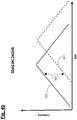
- Figure 4a shows initially only a schematic representation of a basic structure known per se, in which a light source that can be spectrally tuned 410 transmitted signal 411 with a frequency that has changed over time (also referred to as "chirp") is split into two partial signals, this splitting taking place, for example, via a beam splitter (not shown) (eg a partially transparent mirror or a fiber-optic splitter).
- the two partial signals are coupled via a signal coupler 445 and superimposed on one another at a detector 450, the first partial signal reaching the signal coupler 445 and detector 450 as reference signal 422 without reflection on the object labeled "440".
- the second partial signal arriving at the signal coupler 445 or the detector 450 runs as a measurement signal 421 via an optical circulator 420 and a scanner 430 to the object 440, is reflected back by this and thus reaches the object 440 with a time delay and a correspondingly changed frequency compared to the reference signal 422 Signal coupler 445 and to detector 450.
- the detector signal supplied by the detector 450 is evaluated via an evaluation device 460, the detected signal at a specific point in time being shown in the diagram of Figure 4b
- the difference frequency 431 shown between measurement signal 421 and reference signal 422 is characteristic of the distance of the object 440 from the measurement device or the light source 410.
- the time-dependent frequency profile of the signal 411 emitted by the light source 410 can also be designed in such a way that there are two sections in which the time derivative of the Light source 410 generated frequency is opposite to each other.
- a distance-dependent beat signal is produced, the frequency of which can be determined from the chirp rate ⁇ .
- the invention now makes use of the fact that corresponding (dirt or precipitation) particles on the front or protective pane can in principle also be viewed as objects, which in turn in the form of a peak in the signal spectrum obtained on the basis of a Fourier transformation of the beat signal can be detected.
- the desired contamination diagnosis can now be made according to the invention take place via an analysis of the signal spectrum in the relevant area of low frequencies (hereinafter referred to as "analysis area pollution").
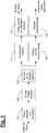
- Fig. 1 shows a merely schematic representation to illustrate the principle. According to Fig. 1 this is achieved as above using Figure 4a
- the superimposition signal generated from the measurement and reference signal is initially generated in a detector and amplifier unit labeled "101" and then in an analog-digital converter 102.
- the beat signal generated by this analog-digital converter 102 is used in a manner known per se a signal spectrum is calculated using a Fourier transform (block 103).
- a “search area objects” 111 is distinguished from a “pollution analysis area” 121.
- an upper limit frequency limiting the analysis frequency range is smaller than the maximum frequency occurring in the signal spectrum evaluated by the evaluation device for determining distance values of the object.
- the analysis frequency range limiting upper limit frequency not greater than 2MHz, in particular not greater than 1MHz.
- the specified "contamination analysis area" 121 can be selected merely by way of example so that it only includes frequencies up to a maximum frequency of 2 MHz, in particular up to a maximum frequency of 1 MHz.
- the "contamination analysis area” 121 as well as the "objects search area” 111 can be selected depending on the current beam direction, which can take into account the fact that the outgoing measuring beam different distances to the front depending on the beam or scanning direction - or the protective screen is put back.
- the analysis of the signal spectrum within the above-mentioned "pollution analysis range” can in particular include the determination of the height of a peak detected in this frequency range. It is assumed here that the peak height is proportional to the proportion of scattered light and proportional to the degree of pollution.
- Fig. 2a shows, in an exaggerated representation that is not true to scale, exemplary scenarios of a comparatively low level of pollution ( Fig. 2a ) and a comparatively heavy pollution ( Figure 2b ).
- the degree of pollution increases, the peak to be assigned to the object to be measured with regard to its distance becomes smaller and the pollution-related peak occurring in the low-frequency "analysis area pollution" increases.
- the beam is comparatively large in relation to the contamination that occurs (a typical diameter of the beam being 15 mm, for example can) and the (front or protective) pane is arranged in the vicinity of the exit pupil. In this case, a higher degree of pollution leads to a higher peak.
- the total energy in said frequency range of the signal spectrum can also be determined (e.g. by integrating the squared signal level over the corresponding frequency range).
- the fluctuation over time of the peak intensity can additionally or alternatively also be evaluated. Since this temporal fluctuation of the peak intensity, for example when there is rain or snow on the front or protective window, is significantly greater than when dirt particles accumulate on the front or protective window, by determining the temporal fluctuation of the peak intensity between rain and snow on the one hand and On the other hand, pollution can be distinguished.
- the operation of the LIDAR system is automatically modified according to the invention.
- This can include the initiation of suitable remedial measures (e.g. cleaning with high-pressure water to remove dirt particles or heating to remove snow or ice) and / or a temporary shutdown or operational interruption of the LIDAR system.
- an angular range can also be identified in which a sufficient signal is not to be expected or where it cannot be reliably measured. With smaller beam diameters, the said angular range can be determined more precisely.
- remedial measures or operational interruptions of the LIDAR system can be carried out immediately or (e.g. when the vehicle is next stopped), possibly also preventively.
- Said protective pane of the LIDAR system should preferably be designed in such a way that there is no direct reflection of the measurement signal into the detector or the receiver channel over the entire scanning area and only scattered light emanating from the dirt particles or precipitation is detected.
- Fig. 3 shows a merely schematic and greatly simplified representation to explain a possible structure with which the method according to the invention can be implemented.
- "300” denotes a LIDAR system
- "320” denotes a (protective) pane that is transparent to a light emitted by the light source of the LIDAR system 300
- "325" denotes a mechanical mount of this disk 320.
- Indicated and designated by “330” are particles located on the disk 320 (eg dirt particles or precipitation) as well as different exemplary directions (and in each case indicated by dashed arrows) of the scattered light emanating from these particles.
- Fig. 3 indicated can be achieved via a suitable geometry or an inclined position of the pane 320 relative to the LIDAR system 300 that only scattered light enters the detector or the receiver channel of the LIDAR system, but not the direct (specular) reflection of the measurement signal.
- a direct reflex that occurs can also be accepted and, if necessary, used to check the function of the LIDAR system or the scanning process (since the direct reflex, in contrast to a peak due to scattered light, can only be observed during the scanning operation).
- the signal strength of the direct reflection with regard to the detector can also be optimized by means of a suitable coating, for example a front or protective pane.
Landscapes
- Engineering & Computer Science (AREA)
- Physics & Mathematics (AREA)
- Electromagnetism (AREA)
- Computer Networks & Wireless Communication (AREA)
- General Physics & Mathematics (AREA)
- Radar, Positioning & Navigation (AREA)
- Remote Sensing (AREA)
- Mechanical Engineering (AREA)
- Optical Radar Systems And Details Thereof (AREA)
Applications Claiming Priority (1)
| Application Number | Priority Date | Filing Date | Title |
|---|---|---|---|
| DE102019135570.2A DE102019135570A1 (de) | 2019-12-20 | 2019-12-20 | Verfahren zum Betreiben eines LIDAR-Systems, sowie LIDAR-System |
Publications (1)
| Publication Number | Publication Date |
|---|---|
| EP3839558A1 true EP3839558A1 (fr) | 2021-06-23 |
Family
ID=73789841
Family Applications (1)
| Application Number | Title | Priority Date | Filing Date |
|---|---|---|---|
| EP20212617.3A Pending EP3839558A1 (fr) | 2019-12-20 | 2020-12-09 | Procédé de fonctionnement d'un système lidar ainsi que système lidar |
Country Status (3)
| Country | Link |
|---|---|
| US (1) | US12345817B2 (fr) |
| EP (1) | EP3839558A1 (fr) |
| DE (1) | DE102019135570A1 (fr) |
Families Citing this family (5)
| Publication number | Priority date | Publication date | Assignee | Title |
|---|---|---|---|---|
| US10969491B1 (en) * | 2020-08-14 | 2021-04-06 | Aeva, Inc. | LIDAR window blockage detection |
| US20230243941A1 (en) * | 2022-02-01 | 2023-08-03 | Luminar, Llc | Lidar window blockage detection |
| JP2023160134A (ja) * | 2022-04-21 | 2023-11-02 | 株式会社Screenホールディングス | 粒状物処理装置および粒状物処理方法 |
| US20230408689A1 (en) * | 2022-06-15 | 2023-12-21 | Datalogic IP Tech, S.r.l. | Optical detection of objects having irregular surfaces |
| DE102024202347A1 (de) * | 2024-03-13 | 2025-09-18 | Zf Friedrichshafen Ag | Verbesserung der Objektdetektion eines Lidarsensors |
Citations (6)
| Publication number | Priority date | Publication date | Assignee | Title |
|---|---|---|---|---|
| DE102004028860A1 (de) | 2003-06-20 | 2005-01-05 | Denso Corp., Kariya | Objekterkennungsvorrichtung, die dafür vorgesehen ist, ein Anhaften von Schmutz an einem Radar zu erfassen |
| US20070040727A1 (en) * | 2005-08-16 | 2007-02-22 | Mitsubishi Denki Kabushiki Kaisha | Radar device |
| DE102005054497A1 (de) | 2005-11-16 | 2007-05-31 | Daimlerchrysler Ag | Kraftfahrzeug mit Rücklichtern und einer Auffahrwarnvorrichtung |
| US20150177367A1 (en) * | 2013-12-19 | 2015-06-25 | DSCG Solutions, Inc. | Single laser lidar system |
| US20180046183A1 (en) * | 2016-08-15 | 2018-02-15 | Ford Global Technologies, Llc | Lidar sensor frost detection |
| US20180188362A1 (en) * | 2015-06-24 | 2018-07-05 | Konica Minolta, Inc. | Objective sensor, objective sensor dirt determination method, and object detection device |
Family Cites Families (8)
| Publication number | Priority date | Publication date | Assignee | Title |
|---|---|---|---|---|
| JP3428009B2 (ja) * | 1998-07-03 | 2003-07-22 | トヨタ自動車株式会社 | 車両用レーダ装置 |
| DE102009000469A1 (de) * | 2009-01-29 | 2010-08-19 | Robert Bosch Gmbh | Verfahren zur Detektion von Niederschlag mit einem Radarortungsgerät für Kraftfahrzeuge |
| SG11201606510XA (en) * | 2014-03-14 | 2016-09-29 | Heptagon Micro Optics Pte Ltd | Optoelectronic modules operable to recognize spurious reflections and to compensate for errors caused by spurious reflections |
| KR101877388B1 (ko) * | 2016-07-21 | 2018-07-11 | 엘지전자 주식회사 | 차량용 라이다 장치 |
| US10254388B2 (en) * | 2017-03-28 | 2019-04-09 | Luminar Technologies, Inc. | Dynamically varying laser output in a vehicle in view of weather conditions |
| WO2019064062A1 (fr) * | 2017-09-26 | 2019-04-04 | Innoviz Technologies Ltd. | Systèmes et procédés de détection et localisation par la lumière |
| US10340651B1 (en) * | 2018-08-21 | 2019-07-02 | Luminar Technologies, Inc. | Lidar system with optical trigger |
| US11519840B2 (en) * | 2019-01-22 | 2022-12-06 | Ford Global Technologies, Llc | Hydrophobic coating characterization |
-
2019
- 2019-12-20 DE DE102019135570.2A patent/DE102019135570A1/de not_active Withdrawn
-
2020
- 2020-12-09 EP EP20212617.3A patent/EP3839558A1/fr active Pending
- 2020-12-17 US US17/125,574 patent/US12345817B2/en active Active
Patent Citations (6)
| Publication number | Priority date | Publication date | Assignee | Title |
|---|---|---|---|---|
| DE102004028860A1 (de) | 2003-06-20 | 2005-01-05 | Denso Corp., Kariya | Objekterkennungsvorrichtung, die dafür vorgesehen ist, ein Anhaften von Schmutz an einem Radar zu erfassen |
| US20070040727A1 (en) * | 2005-08-16 | 2007-02-22 | Mitsubishi Denki Kabushiki Kaisha | Radar device |
| DE102005054497A1 (de) | 2005-11-16 | 2007-05-31 | Daimlerchrysler Ag | Kraftfahrzeug mit Rücklichtern und einer Auffahrwarnvorrichtung |
| US20150177367A1 (en) * | 2013-12-19 | 2015-06-25 | DSCG Solutions, Inc. | Single laser lidar system |
| US20180188362A1 (en) * | 2015-06-24 | 2018-07-05 | Konica Minolta, Inc. | Objective sensor, objective sensor dirt determination method, and object detection device |
| US20180046183A1 (en) * | 2016-08-15 | 2018-02-15 | Ford Global Technologies, Llc | Lidar sensor frost detection |
Also Published As
| Publication number | Publication date |
|---|---|
| DE102019135570A1 (de) | 2021-06-24 |
| US20210190951A1 (en) | 2021-06-24 |
| US12345817B2 (en) | 2025-07-01 |
Similar Documents
| Publication | Publication Date | Title |
|---|---|---|
| EP3839558A1 (fr) | Procédé de fonctionnement d'un système lidar ainsi que système lidar | |
| DE102016005021B4 (de) | Verfahren und Vorrichtung zur Messung der Tiefe der Dampfkapillare während eines Bearbeitungsprozesses mit einem Hochenergiestrahl | |
| WO2007014595A1 (fr) | Procede pour determiner une limitation en profondeur d'un creneau de stationnement au moyen de capteurs a ultrasons et systeme associe | |
| DE102012107445A1 (de) | Verfahren zur Klassifizierung von fahrenden Fahrzeugen | |
| EP2401630B1 (fr) | Procédé de détection de givrage sur un capteur de radar à résolution angulaire dans un système d'aide à la conduite pour véhicules à moteur | |
| DE10149768A1 (de) | Sichtweitenbestimmung | |
| EP2479586B1 (fr) | Procédé destiné à l'évaluation d'un degré d'impureté d'un disque frontal d'un dispositif de saisie optique et dispositif de saisie optique | |
| DE102015200014A1 (de) | Vorrichtung und Verfahren zum Bestimmen einer Eigenschaft eines Objekts | |
| EP2607922A1 (fr) | Procédé et agencement de saisie de données de mesure d'un véhicule dans un champ de radar | |
| WO2017097654A1 (fr) | Procédé de détection d'un dysfonctionnement d'un dispositif de balayage laser, dispositif de balayage laser et véhicule à moteur | |
| EP3591424B1 (fr) | Caméra d'évaluation du temps de propagation de la lumière 3d et procédé de détection de données d'image tridimensionnelles | |
| DE102015007034B4 (de) | Verfahren zum Betrieb eines Parkassistenzsystems eines Kraftfahrzeugs und Kraftfahrzeug | |
| DE102020107450A1 (de) | Lidar-Sensoreinrichtung für ein Kraftfahrzeug, Verfahren zum Betrieb einer Lidar-Sensoreinrichtung und Kraftfahrzeug | |
| DE102004038239A1 (de) | Luftfeder mit integrierter optischer Höhenstandssensorik | |
| DE102006012413A1 (de) | Objekterfassungsvorrichtung für ein Fahrzeug | |
| DE3816416A1 (de) | Verfahren und vorrichtung zum erfassen des wetterbedingten glaettezustands eines fahrbahnbelag | |
| EP0674184B1 (fr) | Procédé et dispositif de classification de véhicules utilisant un radar pour trafic | |
| EP2690398B1 (fr) | Dispositif de détermination de la position d'éléments mécaniques | |
| DE10210472B4 (de) | Verfahren zur Justierung der Ausrichtung einer Sensoreinheit und Vorrichtung zur Durchführung des Verfahrens | |
| DE19626187C2 (de) | Verfahren und Anordnung zur Detektion von Objekten | |
| WO2007137835A2 (fr) | Procédé et ensemble permettant de déterminer la qualité optique d'une vitre transparente | |
| DE102020210061A1 (de) | Verfahren zum Betreiben eines LiDAR-Systems und zugehörige Vorrichtung | |
| DE102007046441A1 (de) | Vorrichtung und Verfahren zur Radialspaltmessung mit Millimeterwellen | |
| EP3916372A1 (fr) | Dispositif de mesure | |
| DE102004056380B4 (de) | Messvorrichtung und Verfahren zur Messung eines freifliegenden Körpers |
Legal Events
| Date | Code | Title | Description |
|---|---|---|---|
| PUAI | Public reference made under article 153(3) epc to a published international application that has entered the european phase |
Free format text: ORIGINAL CODE: 0009012 |
|
| STAA | Information on the status of an ep patent application or granted ep patent |
Free format text: STATUS: THE APPLICATION HAS BEEN PUBLISHED |
|
| AK | Designated contracting states |
Kind code of ref document: A1 Designated state(s): AL AT BE BG CH CY CZ DE DK EE ES FI FR GB GR HR HU IE IS IT LI LT LU LV MC MK MT NL NO PL PT RO RS SE SI SK SM TR |
|
| STAA | Information on the status of an ep patent application or granted ep patent |
Free format text: STATUS: REQUEST FOR EXAMINATION WAS MADE |
|
| 17P | Request for examination filed |
Effective date: 20210623 |
|
| RBV | Designated contracting states (corrected) |
Designated state(s): AL AT BE BG CH CY CZ DE DK EE ES FI FR GB GR HR HU IE IS IT LI LT LU LV MC MK MT NL NO PL PT RO RS SE SI SK SM TR |
|
| STAA | Information on the status of an ep patent application or granted ep patent |
Free format text: STATUS: EXAMINATION IS IN PROGRESS |
|
| 17Q | First examination report despatched |
Effective date: 20240514 |