EP3840006B1 - Active and passive fuse module - Google Patents
Active and passive fuse module Download PDFInfo
- Publication number
- EP3840006B1 EP3840006B1 EP20214274.1A EP20214274A EP3840006B1 EP 3840006 B1 EP3840006 B1 EP 3840006B1 EP 20214274 A EP20214274 A EP 20214274A EP 3840006 B1 EP3840006 B1 EP 3840006B1
- Authority
- EP
- European Patent Office
- Prior art keywords
- fuse
- pyrotechnic
- piston
- fuse element
- ignitor
- Prior art date
- Legal status (The legal status is an assumption and is not a legal conclusion. Google has not performed a legal analysis and makes no representation as to the accuracy of the status listed.)
- Active
Links
Images

Classifications
-
- H—ELECTRICITY
- H01—ELECTRIC ELEMENTS
- H01H—ELECTRIC SWITCHES; RELAYS; SELECTORS; EMERGENCY PROTECTIVE DEVICES
- H01H89/00—Combinations of two or more different basic types of electric switches, relays, selectors and emergency protective devices, not covered by any single one of the other main groups of this subclass
-
- H—ELECTRICITY
- H01—ELECTRIC ELEMENTS
- H01H—ELECTRIC SWITCHES; RELAYS; SELECTORS; EMERGENCY PROTECTIVE DEVICES
- H01H39/00—Switching devices actuated by an explosion produced within the device and initiated by an electric current
- H01H39/006—Opening by severing a conductor
-
- H—ELECTRICITY
- H02—GENERATION; CONVERSION OR DISTRIBUTION OF ELECTRIC POWER
- H02H—EMERGENCY PROTECTIVE CIRCUIT ARRANGEMENTS
- H02H3/00—Emergency protective circuit arrangements for automatic disconnection directly responsive to an undesired change from normal electric working condition with or without subsequent reconnection ; integrated protection
- H02H3/02—Details
-
- H—ELECTRICITY
- H01—ELECTRIC ELEMENTS
- H01H—ELECTRIC SWITCHES; RELAYS; SELECTORS; EMERGENCY PROTECTIVE DEVICES
- H01H85/00—Protective devices in which the current flows through a part of fusible material and this current is interrupted by displacement of the fusible material when this current becomes excessive
- H01H85/0039—Means for influencing the rupture process of the fusible element
-
- H—ELECTRICITY
- H01—ELECTRIC ELEMENTS
- H01H—ELECTRIC SWITCHES; RELAYS; SELECTORS; EMERGENCY PROTECTIVE DEVICES
- H01H85/00—Protective devices in which the current flows through a part of fusible material and this current is interrupted by displacement of the fusible material when this current becomes excessive
- H01H85/02—Details
-
- H—ELECTRICITY
- H01—ELECTRIC ELEMENTS
- H01H—ELECTRIC SWITCHES; RELAYS; SELECTORS; EMERGENCY PROTECTIVE DEVICES
- H01H85/00—Protective devices in which the current flows through a part of fusible material and this current is interrupted by displacement of the fusible material when this current becomes excessive
- H01H85/02—Details
- H01H85/0241—Structural association of a fuse and another component or apparatus
-
- H—ELECTRICITY
- H02—GENERATION; CONVERSION OR DISTRIBUTION OF ELECTRIC POWER
- H02H—EMERGENCY PROTECTIVE CIRCUIT ARRANGEMENTS
- H02H3/00—Emergency protective circuit arrangements for automatic disconnection directly responsive to an undesired change from normal electric working condition with or without subsequent reconnection ; integrated protection
- H02H3/02—Details
- H02H3/021—Details concerning the disconnection itself, e.g. at a particular instant, particularly at zero value of current, disconnection in a predetermined order
-
- H—ELECTRICITY
- H02—GENERATION; CONVERSION OR DISTRIBUTION OF ELECTRIC POWER
- H02H—EMERGENCY PROTECTIVE CIRCUIT ARRANGEMENTS
- H02H3/00—Emergency protective circuit arrangements for automatic disconnection directly responsive to an undesired change from normal electric working condition with or without subsequent reconnection ; integrated protection
- H02H3/08—Emergency protective circuit arrangements for automatic disconnection directly responsive to an undesired change from normal electric working condition with or without subsequent reconnection ; integrated protection responsive to excess current
-
- H—ELECTRICITY
- H02—GENERATION; CONVERSION OR DISTRIBUTION OF ELECTRIC POWER
- H02H—EMERGENCY PROTECTIVE CIRCUIT ARRANGEMENTS
- H02H5/00—Emergency protective circuit arrangements for automatic disconnection directly responsive to an undesired change from normal non-electric working conditions with or without subsequent reconnection
-
- H—ELECTRICITY
- H01—ELECTRIC ELEMENTS
- H01H—ELECTRIC SWITCHES; RELAYS; SELECTORS; EMERGENCY PROTECTIVE DEVICES
- H01H85/00—Protective devices in which the current flows through a part of fusible material and this current is interrupted by displacement of the fusible material when this current becomes excessive
- H01H85/02—Details
- H01H85/04—Fuses, i.e. expendable parts of the protective device, e.g. cartridges
- H01H85/041—Fuses, i.e. expendable parts of the protective device, e.g. cartridges characterised by the type
- H01H85/048—Fuse resistors
- H01H2085/0483—Fuse resistors with temperature dependent resistor, e.g. thermistor
-
- H—ELECTRICITY
- H01—ELECTRIC ELEMENTS
- H01H—ELECTRIC SWITCHES; RELAYS; SELECTORS; EMERGENCY PROTECTIVE DEVICES
- H01H85/00—Protective devices in which the current flows through a part of fusible material and this current is interrupted by displacement of the fusible material when this current becomes excessive
- H01H85/02—Details
- H01H85/46—Circuit arrangements not adapted to a particular application of the protective device
- H01H2085/466—Circuit arrangements not adapted to a particular application of the protective device with remote controlled forced fusing
Definitions
- This disclosure relates generally to the field of circuit protection devices and relates more particularly to a fuse module that includes both passive and active circuit protection elements.
- Fuses are commonly implemented in electrical systems for providing overcurrent protection. Most fuses are "passive" devices that include fuse elements that are configured to carry a rated amount of electrical current during normal operation. If current flowing through a fuse element exceeds the fuse element's rated current, the fuse element will melt, disintegrate, or otherwise separate, thereby arresting the current to prevent or mitigate damage to connected electrical components.
- PIs pyrotechnic interrupters
- a controller e.g., an airbag control unit, battery management system, etc.
- a controller may send an initiation signal to a PI, causing a pyrotechnic ignitor within the PI to be detonated.
- a resultant increase in pressure within the PI rapidly forces a piston or blade to cut through a conductor that extends through the PI. Electrical current flowing through the PI is thereby interrupted, and the piston, which is formed of a dielectric material, provides an electrically insulating barrier between separated portions of the conductor to prevent electrical arcing therebetween.
- 'A pyrotechnic switching device comprising a first and a second pyrotechnic initiators, and a body in which are present: an electrically conductive portion, and a mobile switching element having an insulating relief facing the conductive portion.
- the device also comprises a fuse element connected in series with the conductive portion, the first initiator being connected to the terminals of the fuse element so that tripping the fuse element actuates the first initiator, each initiator being configured to cause the device to switch from a current conducting configuration to a current interrupting configuration, the mobile switching element being set in motion toward the conductive portion in order to break it by the impact of the relief during switching from the first to the second configuration.
- a fuse module according to the invention is defined in independent claim 1. Further embodiments are described by the dependent claims.
- a fuse module in accordance with the present disclosure will now be described more fully with reference to the accompanying drawings, in which preferred embodiments of the fuse module are presented. It will be understood, however, that the fuse module may be embodied in many different forms and should not be construed as being limited to the embodiments set forth herein. Rather, these embodiments are provided so that this disclosure will convey certain exemplary aspects of the fuse module to those skilled in the art.
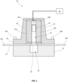
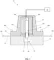
- FIGS. 1 and 2 cross-sectional views illustrating a fuse module 10 (hereinafter “the fuse module 10") in accordance with an exemplary, non-limiting embodiment of the present disclosure are shown.
- the fuse module 10 a fuse module 10
- terms such as “front,” “rear,” “top,” “bottom,” “up,” “down,” “vertical,” and “horizontal” may be used herein to describe the relative placement and orientation of various components of the fuse module 10, each with respect to the geometry and orientation of the fuse module 10 as it appears in FIGS. 1 and 2 .
- Said terminology will include the words specifically mentioned, derivatives thereof, and words of similar import.
- the fuse module 10 includes a base 12, a busbar 14, and a pyrotechnic interrupter (PI) 18.
- the base 12 is formed from electrically insulating material, such as plastic, polymer, ceramic, etc. The present disclosure is not limited in this regard.
- the base 12 includes a cavity 20 formed in a top surface thereof
- the busbar 14 may be formed from a single piece or length of conductive material (e.g., stamped from a single sheet of copper or the like) and includes a fuse element 22 and first and second terminal portions 26a, 26b extending from opposite ends of the fuse element 22.
- the busbar 14 is disposed on the top surface of the base 12 in a horizontal orientation with the fuse element 22 extending over the cavity 20.
- the first and second terminal portions 26a, 26b may extend outside of, or beyond, the sides of the base 12 for facilitating connection of the fuse module 10 within a circuit.
- the fuse element 22 may be configured to melt, disintegrate, or otherwise open if current flowing through the busbar 14 exceeds a predetermined threshold, or "current rating," of the fuse module 10.
- the fuse element 22 may include perforations, slots, thinned or narrowed segments, and/or various other features for making the fuse element 22 more susceptible to melting or opening than other portions of the busbar 14.
- the fuse element 22 may be configured to have a current rating in a range between 30 amps and 1000 amps. The present disclosure is not limited in this regard.
- the PI 18 may include a housing 36 having a mounting flange 38 projecting from a lower portion thereof.
- the housing 36 may be disposed atop the base 12 with mechanical fasteners 40a, 40b extending through the mounting flange 38 and into the base 12 for fastening the components together in a vertically stacked relationship.
- the housing 36 includes a hollow, vertically oriented shaft 43 extending therethrough.
- the shaft 43 may have an open bottom end located directly above the fuse element 22 and the cavity 20.
- the housing 36 contains a movable piston or blade 42 (hereinafter “the piston 42") disposed within a hollow shaft 43 located above the cavity 20 of the base 12.
- the housing 36 further contains a first pyrotechnic ignitor 44a disposed within the shaft 43 above the piston 42.
- the first pyrotechnic ignitor 44a may be coupled to a controller 45 (e.g., an airbag control unit, battery management system, etc. of an automobile).
- a controller 45 e.g., an airbag control unit, battery management system, etc. of an automobile.
- the controller 45 may send an initiation signal to the pyrotechnic ignitor 44a, causing the pyrotechnic ignitor 44 to be detonated.
- Electrical current flowing through the busbar 14 is thereby interrupted, and the piston 42, which may be formed of a dielectric material, may provide an electrically insulating barrier between the separated ends of the fuse element 22 to prevent electrical arcing therebetween.
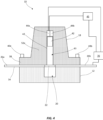
- the fuse module 10 may additionally or alternatively include an "arc triggering" capability, wherein a second pyrotechnic ignitor 44b is disposed within the shaft 43 adjacent the first pyrotechnic ignitor 44a.
- a pair of leads 52a, 52b extend from the second pyrotechnic ignitor 44b to the first and second terminal portions 26a, 26b, respectively.
- the leads 52a, 52b extend through/across the shaft 43 below the piston 42.
- the fuse element 22 is melted (e.g., upon occurrence of an overcurrent condition)
- the voltage across the separated first and second terminal portions 26a, 26b creates sufficient current in the leads 52a, 52b to cause the second pyrotechnic ignitor 44b to be detonated.
- a resultant increase in pressure within the shaft 43 rapidly forces the piston 42 downwardly in the shaft 43, through the fuse element 22 of the busbar 14 (as described above and as shown in FIG. 2 ).
- the piston 42 severs the leads 52a, 52b to eliminate any potential alternative current paths between the first and second terminal portions 26a, 26b.
- the leads 52a, 52b may be severed at various locations other than within the shaft 43 and by structures other than the piston 42.
- the leads 52a, 52b instead of extending through the shaft 43, may extend through the cavity 20 or elsewhere adjacent the shaft 43.
- the leads 52a, 52b may be located outside of or away from the path of the piston 43 and, instead of being severed directly by the piston 43, may be severed by a shank or protrusion extending from the piston 43 or by an electrical/mechanical structure or device that may be triggered by movement of the piston 43.
- the fuse element 22 begins to separate (e.g., melts) before the pyrotechnic ignitor 44b detonates and drives the piston 42, the fuse element 22 is weakened (e.g. partially melted) before the piston 42 is driven therethrough, making it easier for the piston 42 to cut through the fuse element 22.
- the fuse element 22 may be thicker/larger (and therefore capable of handling higher currents) than would be possible if the piston 42 were required to break through an unweakened portion of the busbar 14 (i.e., a portion of the busbar 14 other than the partially melted fuse element 22) as in conventional fuse modules incorporating pyrotechnic interrupters.
- fuse module 10 includes a first pyrotechnic ignitor 44a coupled to the controller 45 and a second pyrotechnic ignitor 44b coupled to the first and second terminal portions 26a, 26b of the busbar 14, respectively, embodiments of the present disclosure are contemplated in which the first pyrotechnic ignitor 44a and the controller 45 are omitted, and wherein the fuse module 10 includes only a single pyrotechnic ignitor connected to the busbar 14 and configured to be detonated upon separation of the fuse element 22 (as described above with respect to the second pyrotechnic ignitor 44b).
- a positive temperature coefficient (PTC) element 60 may be connected in parallel with the fuse module 10.
- the PTC element 60 may be formed of any type of PTC material (e.g., polymeric PTC material, ceramic PTC material, etc.) formulated to have an electrical resistance that increases as the temperature of the PTC element 60 increases.
- the PTC element 60 may have a predetermined "trip temperature" above which the electrical resistance of the PTC element 60 rapidly and drastically increases (e.g., in a nonlinear fashion) in order to substantially arrest current passing therethrough.
- the PTC element 60 may have, within its normal operating temperature range (i.e., below its trip temperature), a resistance that is greater than a resistance of the fuse element 22.
- a current sensing module 70 (e.g., a current sensor with a microprocessor) may be connected to one of the terminal portions 26a, 26b of the busbar 14 and to the pyrotechnic ignitor 44a of the PI 18.
- the current sensing module 70 may be configured to measure a current in the busbar 14 and, upon detection of a current above a predefined threshold, may send an initiation signal to the pyrotechnic ignitor 44a, detonating the pyrotechnic ignitor 44a and breaking the fuse element 22 as described above.
- the current sensing module 70 may be programmed to send the initiation signal immediately or after a desired, predetermined amount of time (e.g., 10 milliseconds) and in response to detecting a desired, predetermined amount of current in the busbar 14.
- the current sensing module 70 may also be connected to the controller 45, and the current sensing module 70 may be configured to send an initiation signal to the pyrotechnic ignitor 44a only if certain predetermined conditions are met.
- the current sensing module 70 may be configured to send an initiation signal to the pyrotechnic ignitor 44a if the current sensing module 70 detects more than a predetermined amount of current in the busbar 14 and if the controller 45 provides an indication of a collision to the current sensing module 70.
- the fuse modules of the present disclosure facilitate the implementation of both passive and active circuit protection elements (e.g., conventional fuse elements and a pyrotechnic interrupter) in single, compact, space-saving form factor that facilitates convenient installation for various applications.
- passive and active circuit protection elements e.g., conventional fuse elements and a pyrotechnic interrupter
Landscapes
- Engineering & Computer Science (AREA)
- Power Engineering (AREA)
- Fuses (AREA)
Applications Claiming Priority (3)
| Application Number | Priority Date | Filing Date | Title |
|---|---|---|---|
| US201962948728P | 2019-12-16 | 2019-12-16 | |
| US202063036613P | 2020-06-09 | 2020-06-09 | |
| US17/021,774 US11387068B2 (en) | 2019-12-16 | 2020-09-15 | Active/passive fuse module |
Publications (2)
| Publication Number | Publication Date |
|---|---|
| EP3840006A1 EP3840006A1 (en) | 2021-06-23 |
| EP3840006B1 true EP3840006B1 (en) | 2024-04-10 |
Family
ID=73854624
Family Applications (1)
| Application Number | Title | Priority Date | Filing Date |
|---|---|---|---|
| EP20214274.1A Active EP3840006B1 (en) | 2019-12-16 | 2020-12-15 | Active and passive fuse module |
Country Status (3)
| Country | Link |
|---|---|
| EP (1) | EP3840006B1 (ja) |
| JP (1) | JP7676696B2 (ja) |
| CN (1) | CN112993926B (ja) |
Cited By (1)
| Publication number | Priority date | Publication date | Assignee | Title |
|---|---|---|---|---|
| EP4307333B1 (en) * | 2022-07-14 | 2026-01-28 | Littelfuse, Inc. | Active/passive fuse module |
Families Citing this family (5)
| Publication number | Priority date | Publication date | Assignee | Title |
|---|---|---|---|---|
| EP4374408A4 (en) * | 2021-07-20 | 2024-10-16 | Littelfuse International Holding, LLC | ACTIVE/PASSIVE SECURITY MODULE |
| CN113539763B (zh) * | 2021-08-09 | 2025-09-05 | 西安中熔电气股份有限公司 | 一种嵌套式打断导体和熔体的激励保护装置 |
| CN114446736A (zh) * | 2022-01-13 | 2022-05-06 | 宁波峰梅新能源汽车科技有限公司 | 一种爆炸保险丝 |
| CN115036193B (zh) * | 2022-03-22 | 2026-04-14 | 西安中熔电气股份有限公司 | 一种高可靠性主被动一体保护装置 |
| US20260005506A1 (en) * | 2022-06-07 | 2026-01-01 | Panasonic Intellectual Property Management Co., Ltd. | Dc short circuit protection device |
Family Cites Families (10)
| Publication number | Priority date | Publication date | Assignee | Title |
|---|---|---|---|---|
| US5990572A (en) * | 1997-02-28 | 1999-11-23 | Harness System Technologies Research, Ltd. | Electric circuit breaker for vehicle |
| DE10049071B4 (de) | 2000-10-02 | 2004-12-16 | Micronas Gmbh | Sicherungsvorrichtung für einen Stromkreis insbesondere in Kraftfahrzeugen |
| KR20160035588A (ko) | 2013-07-26 | 2016-03-31 | 타이코 일렉트로닉스 저팬 지.케이. | 보호 디바이스 |
| FR3014594B1 (fr) * | 2013-12-09 | 2016-01-01 | Ncs Pyrotechnie & Tech | Coupe-circuit pyrotechnique |
| DE202015106793U1 (de) | 2015-12-14 | 2016-01-14 | Kromberg & Schubert Gmbh | Schmelzsicherung |
| DE102017203851B4 (de) * | 2016-11-28 | 2018-06-14 | Volkswagen Aktiengesellschaft | Elektrische Sicherung, Verfahren zum Betreiben einer elektrischen Sicherung und elektrisches Traktionsnetz |
| DE102016124176A1 (de) * | 2016-12-13 | 2017-01-26 | Peter Lell | Elektrisches Unterbrechungsschaltglied, insbesondere zum Unterbrechen von hohen Strömen bei hohen Spannungen |
| CN207939189U (zh) * | 2017-08-28 | 2018-10-02 | 比亚迪股份有限公司 | 断路器 |
| FR3073664B1 (fr) * | 2017-11-14 | 2019-12-06 | Arianegroup Sas | Dispositif de coupure pyrotechnique |
| KR102755711B1 (ko) | 2018-06-04 | 2025-01-15 | 다이헤요 세코 가부시키가이샤 | 전기 회로 차단 장치 |
-
2020
- 2020-11-26 JP JP2020196268A patent/JP7676696B2/ja active Active
- 2020-12-14 CN CN202011471937.9A patent/CN112993926B/zh active Active
- 2020-12-15 EP EP20214274.1A patent/EP3840006B1/en active Active
Cited By (1)
| Publication number | Priority date | Publication date | Assignee | Title |
|---|---|---|---|---|
| EP4307333B1 (en) * | 2022-07-14 | 2026-01-28 | Littelfuse, Inc. | Active/passive fuse module |
Also Published As
| Publication number | Publication date |
|---|---|
| CN112993926A (zh) | 2021-06-18 |
| JP7676696B2 (ja) | 2025-05-15 |
| EP3840006A1 (en) | 2021-06-23 |
| JP2021097038A (ja) | 2021-06-24 |
| CN112993926B (zh) | 2023-08-01 |
Similar Documents
| Publication | Publication Date | Title |
|---|---|---|
| US11387068B2 (en) | Active/passive fuse module | |
| EP3840006B1 (en) | Active and passive fuse module | |
| JP7587535B2 (ja) | 電気回路遮断器 | |
| EP3736846B1 (en) | Active/passive automotive fuse module | |
| US11594391B2 (en) | Active/passive fuse module | |
| JP2021077630A (ja) | 火工式機構を組み込んだスイッチング装置に用いられるコンタクト浮揚トリガ機構 | |
| JP2002512422A (ja) | 特に高電流強さ用電気回路の分離装置 | |
| KR20200024114A (ko) | 파이로테크닉 피처를 포함하는 스위칭 디바이스와 함께 사용을 위한 수동형 트리거링 메커니즘 | |
| US11276535B2 (en) | Passive triggering mechanisms for use with switching devices incorporating pyrotechnic features | |
| US20200321181A1 (en) | Pyrotechnic switching device | |
| KR102477042B1 (ko) | 액츄에이터를 사용한 직류 전류 전기 회로 차단 스위치 조립체 | |
| US6504467B1 (en) | Switch integral in a semiconductor element | |
| US12057280B2 (en) | Pyrotechnic circuit breaker | |
| EP4307333B1 (en) | Active/passive fuse module | |
| EP4374408A1 (en) | Active/passive fuse module | |
| KR102926328B1 (ko) | 직류 전기 회로 차단 스위치 어셈블리 | |
| US20210066011A1 (en) | Device for Interrupting an Electrical Current Circuit | |
| CN221642288U (zh) | 断路保护装置、动力电池系统以及电动汽车 | |
| CN121483941A (zh) | 智能熔断器 | |
| JP2023074076A (ja) | 回路遮断器 |
Legal Events
| Date | Code | Title | Description |
|---|---|---|---|
| PUAI | Public reference made under article 153(3) epc to a published international application that has entered the european phase |
Free format text: ORIGINAL CODE: 0009012 |
|
| STAA | Information on the status of an ep patent application or granted ep patent |
Free format text: STATUS: THE APPLICATION HAS BEEN PUBLISHED |
|
| AK | Designated contracting states |
Kind code of ref document: A1 Designated state(s): AL AT BE BG CH CY CZ DE DK EE ES FI FR GB GR HR HU IE IS IT LI LT LU LV MC MK MT NL NO PL PT RO RS SE SI SK SM TR |
|
| STAA | Information on the status of an ep patent application or granted ep patent |
Free format text: STATUS: REQUEST FOR EXAMINATION WAS MADE |
|
| 17P | Request for examination filed |
Effective date: 20211222 |
|
| RBV | Designated contracting states (corrected) |
Designated state(s): AL AT BE BG CH CY CZ DE DK EE ES FI FR GB GR HR HU IE IS IT LI LT LU LV MC MK MT NL NO PL PT RO RS SE SI SK SM TR |
|
| GRAP | Despatch of communication of intention to grant a patent |
Free format text: ORIGINAL CODE: EPIDOSNIGR1 |
|
| STAA | Information on the status of an ep patent application or granted ep patent |
Free format text: STATUS: GRANT OF PATENT IS INTENDED |
|
| INTG | Intention to grant announced |
Effective date: 20231106 |
|
| RIC1 | Information provided on ipc code assigned before grant |
Ipc: H01H 85/46 20060101ALN20231020BHEP Ipc: H01H 85/048 20060101ALN20231020BHEP Ipc: H01H 85/00 20060101ALI20231020BHEP Ipc: H01H 39/00 20060101AFI20231020BHEP |
|
| GRAS | Grant fee paid |
Free format text: ORIGINAL CODE: EPIDOSNIGR3 |
|
| GRAA | (expected) grant |
Free format text: ORIGINAL CODE: 0009210 |
|
| STAA | Information on the status of an ep patent application or granted ep patent |
Free format text: STATUS: THE PATENT HAS BEEN GRANTED |
|
| AK | Designated contracting states |
Kind code of ref document: B1 Designated state(s): AL AT BE BG CH CY CZ DE DK EE ES FI FR GB GR HR HU IE IS IT LI LT LU LV MC MK MT NL NO PL PT RO RS SE SI SK SM TR |
|
| REG | Reference to a national code |
Ref country code: GB Ref legal event code: FG4D |
|
| REG | Reference to a national code |
Ref country code: CH Ref legal event code: EP |
|
| P01 | Opt-out of the competence of the unified patent court (upc) registered |
Effective date: 20240326 |
|
| REG | Reference to a national code |
Ref country code: DE Ref legal event code: R096 Ref document number: 602020028679 Country of ref document: DE |
|
| REG | Reference to a national code |
Ref country code: IE Ref legal event code: FG4D |
|
| REG | Reference to a national code |
Ref country code: LT Ref legal event code: MG9D |
|
| REG | Reference to a national code |
Ref country code: NL Ref legal event code: MP Effective date: 20240410 |
|
| REG | Reference to a national code |
Ref country code: AT Ref legal event code: MK05 Ref document number: 1675804 Country of ref document: AT Kind code of ref document: T Effective date: 20240410 |
|
| PG25 | Lapsed in a contracting state [announced via postgrant information from national office to epo] |
Ref country code: NL Free format text: LAPSE BECAUSE OF FAILURE TO SUBMIT A TRANSLATION OF THE DESCRIPTION OR TO PAY THE FEE WITHIN THE PRESCRIBED TIME-LIMIT Effective date: 20240410 |
|
| PG25 | Lapsed in a contracting state [announced via postgrant information from national office to epo] |
Ref country code: NL Free format text: LAPSE BECAUSE OF FAILURE TO SUBMIT A TRANSLATION OF THE DESCRIPTION OR TO PAY THE FEE WITHIN THE PRESCRIBED TIME-LIMIT Effective date: 20240410 |
|
| PG25 | Lapsed in a contracting state [announced via postgrant information from national office to epo] |
Ref country code: IS Free format text: LAPSE BECAUSE OF FAILURE TO SUBMIT A TRANSLATION OF THE DESCRIPTION OR TO PAY THE FEE WITHIN THE PRESCRIBED TIME-LIMIT Effective date: 20240810 |
|
| PG25 | Lapsed in a contracting state [announced via postgrant information from national office to epo] |
Ref country code: BG Free format text: LAPSE BECAUSE OF FAILURE TO SUBMIT A TRANSLATION OF THE DESCRIPTION OR TO PAY THE FEE WITHIN THE PRESCRIBED TIME-LIMIT Effective date: 20240410 |
|
| PG25 | Lapsed in a contracting state [announced via postgrant information from national office to epo] |
Ref country code: HR Free format text: LAPSE BECAUSE OF FAILURE TO SUBMIT A TRANSLATION OF THE DESCRIPTION OR TO PAY THE FEE WITHIN THE PRESCRIBED TIME-LIMIT Effective date: 20240410 Ref country code: FI Free format text: LAPSE BECAUSE OF FAILURE TO SUBMIT A TRANSLATION OF THE DESCRIPTION OR TO PAY THE FEE WITHIN THE PRESCRIBED TIME-LIMIT Effective date: 20240410 |
|
| PG25 | Lapsed in a contracting state [announced via postgrant information from national office to epo] |
Ref country code: GR Free format text: LAPSE BECAUSE OF FAILURE TO SUBMIT A TRANSLATION OF THE DESCRIPTION OR TO PAY THE FEE WITHIN THE PRESCRIBED TIME-LIMIT Effective date: 20240711 |
|
| PG25 | Lapsed in a contracting state [announced via postgrant information from national office to epo] |
Ref country code: PT Free format text: LAPSE BECAUSE OF FAILURE TO SUBMIT A TRANSLATION OF THE DESCRIPTION OR TO PAY THE FEE WITHIN THE PRESCRIBED TIME-LIMIT Effective date: 20240812 |
|
| PG25 | Lapsed in a contracting state [announced via postgrant information from national office to epo] |
Ref country code: ES Free format text: LAPSE BECAUSE OF FAILURE TO SUBMIT A TRANSLATION OF THE DESCRIPTION OR TO PAY THE FEE WITHIN THE PRESCRIBED TIME-LIMIT Effective date: 20240410 |
|
| PG25 | Lapsed in a contracting state [announced via postgrant information from national office to epo] |
Ref country code: AT Free format text: LAPSE BECAUSE OF FAILURE TO SUBMIT A TRANSLATION OF THE DESCRIPTION OR TO PAY THE FEE WITHIN THE PRESCRIBED TIME-LIMIT Effective date: 20240410 |
|
| PG25 | Lapsed in a contracting state [announced via postgrant information from national office to epo] |
Ref country code: PL Free format text: LAPSE BECAUSE OF FAILURE TO SUBMIT A TRANSLATION OF THE DESCRIPTION OR TO PAY THE FEE WITHIN THE PRESCRIBED TIME-LIMIT Effective date: 20240410 |
|
| PG25 | Lapsed in a contracting state [announced via postgrant information from national office to epo] |
Ref country code: LV Free format text: LAPSE BECAUSE OF FAILURE TO SUBMIT A TRANSLATION OF THE DESCRIPTION OR TO PAY THE FEE WITHIN THE PRESCRIBED TIME-LIMIT Effective date: 20240410 |
|
| PG25 | Lapsed in a contracting state [announced via postgrant information from national office to epo] |
Ref country code: PT Free format text: LAPSE BECAUSE OF FAILURE TO SUBMIT A TRANSLATION OF THE DESCRIPTION OR TO PAY THE FEE WITHIN THE PRESCRIBED TIME-LIMIT Effective date: 20240812 Ref country code: PL Free format text: LAPSE BECAUSE OF FAILURE TO SUBMIT A TRANSLATION OF THE DESCRIPTION OR TO PAY THE FEE WITHIN THE PRESCRIBED TIME-LIMIT Effective date: 20240410 Ref country code: NO Free format text: LAPSE BECAUSE OF FAILURE TO SUBMIT A TRANSLATION OF THE DESCRIPTION OR TO PAY THE FEE WITHIN THE PRESCRIBED TIME-LIMIT Effective date: 20240710 Ref country code: LV Free format text: LAPSE BECAUSE OF FAILURE TO SUBMIT A TRANSLATION OF THE DESCRIPTION OR TO PAY THE FEE WITHIN THE PRESCRIBED TIME-LIMIT Effective date: 20240410 Ref country code: IS Free format text: LAPSE BECAUSE OF FAILURE TO SUBMIT A TRANSLATION OF THE DESCRIPTION OR TO PAY THE FEE WITHIN THE PRESCRIBED TIME-LIMIT Effective date: 20240810 Ref country code: HR Free format text: LAPSE BECAUSE OF FAILURE TO SUBMIT A TRANSLATION OF THE DESCRIPTION OR TO PAY THE FEE WITHIN THE PRESCRIBED TIME-LIMIT Effective date: 20240410 Ref country code: GR Free format text: LAPSE BECAUSE OF FAILURE TO SUBMIT A TRANSLATION OF THE DESCRIPTION OR TO PAY THE FEE WITHIN THE PRESCRIBED TIME-LIMIT Effective date: 20240711 Ref country code: FI Free format text: LAPSE BECAUSE OF FAILURE TO SUBMIT A TRANSLATION OF THE DESCRIPTION OR TO PAY THE FEE WITHIN THE PRESCRIBED TIME-LIMIT Effective date: 20240410 Ref country code: ES Free format text: LAPSE BECAUSE OF FAILURE TO SUBMIT A TRANSLATION OF THE DESCRIPTION OR TO PAY THE FEE WITHIN THE PRESCRIBED TIME-LIMIT Effective date: 20240410 Ref country code: BG Free format text: LAPSE BECAUSE OF FAILURE TO SUBMIT A TRANSLATION OF THE DESCRIPTION OR TO PAY THE FEE WITHIN THE PRESCRIBED TIME-LIMIT Effective date: 20240410 Ref country code: AT Free format text: LAPSE BECAUSE OF FAILURE TO SUBMIT A TRANSLATION OF THE DESCRIPTION OR TO PAY THE FEE WITHIN THE PRESCRIBED TIME-LIMIT Effective date: 20240410 Ref country code: RS Free format text: LAPSE BECAUSE OF FAILURE TO SUBMIT A TRANSLATION OF THE DESCRIPTION OR TO PAY THE FEE WITHIN THE PRESCRIBED TIME-LIMIT Effective date: 20240710 |
|
| REG | Reference to a national code |
Ref country code: DE Ref legal event code: R097 Ref document number: 602020028679 Country of ref document: DE |
|
| PG25 | Lapsed in a contracting state [announced via postgrant information from national office to epo] |
Ref country code: DK Free format text: LAPSE BECAUSE OF FAILURE TO SUBMIT A TRANSLATION OF THE DESCRIPTION OR TO PAY THE FEE WITHIN THE PRESCRIBED TIME-LIMIT Effective date: 20240410 |
|
| PG25 | Lapsed in a contracting state [announced via postgrant information from national office to epo] |
Ref country code: EE Free format text: LAPSE BECAUSE OF FAILURE TO SUBMIT A TRANSLATION OF THE DESCRIPTION OR TO PAY THE FEE WITHIN THE PRESCRIBED TIME-LIMIT Effective date: 20240410 |
|
| PG25 | Lapsed in a contracting state [announced via postgrant information from national office to epo] |
Ref country code: CZ Free format text: LAPSE BECAUSE OF FAILURE TO SUBMIT A TRANSLATION OF THE DESCRIPTION OR TO PAY THE FEE WITHIN THE PRESCRIBED TIME-LIMIT Effective date: 20240410 |
|
| PG25 | Lapsed in a contracting state [announced via postgrant information from national office to epo] |
Ref country code: RO Free format text: LAPSE BECAUSE OF FAILURE TO SUBMIT A TRANSLATION OF THE DESCRIPTION OR TO PAY THE FEE WITHIN THE PRESCRIBED TIME-LIMIT Effective date: 20240410 Ref country code: SK Free format text: LAPSE BECAUSE OF FAILURE TO SUBMIT A TRANSLATION OF THE DESCRIPTION OR TO PAY THE FEE WITHIN THE PRESCRIBED TIME-LIMIT Effective date: 20240410 |
|
| PG25 | Lapsed in a contracting state [announced via postgrant information from national office to epo] |
Ref country code: SM Free format text: LAPSE BECAUSE OF FAILURE TO SUBMIT A TRANSLATION OF THE DESCRIPTION OR TO PAY THE FEE WITHIN THE PRESCRIBED TIME-LIMIT Effective date: 20240410 |
|
| PG25 | Lapsed in a contracting state [announced via postgrant information from national office to epo] |
Ref country code: SM Free format text: LAPSE BECAUSE OF FAILURE TO SUBMIT A TRANSLATION OF THE DESCRIPTION OR TO PAY THE FEE WITHIN THE PRESCRIBED TIME-LIMIT Effective date: 20240410 Ref country code: SK Free format text: LAPSE BECAUSE OF FAILURE TO SUBMIT A TRANSLATION OF THE DESCRIPTION OR TO PAY THE FEE WITHIN THE PRESCRIBED TIME-LIMIT Effective date: 20240410 Ref country code: RO Free format text: LAPSE BECAUSE OF FAILURE TO SUBMIT A TRANSLATION OF THE DESCRIPTION OR TO PAY THE FEE WITHIN THE PRESCRIBED TIME-LIMIT Effective date: 20240410 Ref country code: EE Free format text: LAPSE BECAUSE OF FAILURE TO SUBMIT A TRANSLATION OF THE DESCRIPTION OR TO PAY THE FEE WITHIN THE PRESCRIBED TIME-LIMIT Effective date: 20240410 Ref country code: DK Free format text: LAPSE BECAUSE OF FAILURE TO SUBMIT A TRANSLATION OF THE DESCRIPTION OR TO PAY THE FEE WITHIN THE PRESCRIBED TIME-LIMIT Effective date: 20240410 Ref country code: CZ Free format text: LAPSE BECAUSE OF FAILURE TO SUBMIT A TRANSLATION OF THE DESCRIPTION OR TO PAY THE FEE WITHIN THE PRESCRIBED TIME-LIMIT Effective date: 20240410 |
|
| PLBE | No opposition filed within time limit |
Free format text: ORIGINAL CODE: 0009261 |
|
| STAA | Information on the status of an ep patent application or granted ep patent |
Free format text: STATUS: NO OPPOSITION FILED WITHIN TIME LIMIT |
|
| 26N | No opposition filed |
Effective date: 20250113 |
|
| PG25 | Lapsed in a contracting state [announced via postgrant information from national office to epo] |
Ref country code: SI Free format text: LAPSE BECAUSE OF FAILURE TO SUBMIT A TRANSLATION OF THE DESCRIPTION OR TO PAY THE FEE WITHIN THE PRESCRIBED TIME-LIMIT Effective date: 20240410 |
|
| PG25 | Lapsed in a contracting state [announced via postgrant information from national office to epo] |
Ref country code: MC Free format text: LAPSE BECAUSE OF FAILURE TO SUBMIT A TRANSLATION OF THE DESCRIPTION OR TO PAY THE FEE WITHIN THE PRESCRIBED TIME-LIMIT Effective date: 20240410 |
|
| REG | Reference to a national code |
Ref country code: CH Ref legal event code: PL |
|
| PG25 | Lapsed in a contracting state [announced via postgrant information from national office to epo] |
Ref country code: LU Free format text: LAPSE BECAUSE OF NON-PAYMENT OF DUE FEES Effective date: 20241215 |
|
| GBPC | Gb: european patent ceased through non-payment of renewal fee |
Effective date: 20241215 |
|
| PG25 | Lapsed in a contracting state [announced via postgrant information from national office to epo] |
Ref country code: SE Free format text: LAPSE BECAUSE OF FAILURE TO SUBMIT A TRANSLATION OF THE DESCRIPTION OR TO PAY THE FEE WITHIN THE PRESCRIBED TIME-LIMIT Effective date: 20240410 |
|
| REG | Reference to a national code |
Ref country code: BE Ref legal event code: MM Effective date: 20241231 |
|
| PG25 | Lapsed in a contracting state [announced via postgrant information from national office to epo] |
Ref country code: GB Free format text: LAPSE BECAUSE OF NON-PAYMENT OF DUE FEES Effective date: 20241215 Ref country code: BE Free format text: LAPSE BECAUSE OF NON-PAYMENT OF DUE FEES Effective date: 20241231 |
|
| PG25 | Lapsed in a contracting state [announced via postgrant information from national office to epo] |
Ref country code: CH Free format text: LAPSE BECAUSE OF NON-PAYMENT OF DUE FEES Effective date: 20241231 |
|
| PG25 | Lapsed in a contracting state [announced via postgrant information from national office to epo] |
Ref country code: IE Free format text: LAPSE BECAUSE OF NON-PAYMENT OF DUE FEES Effective date: 20241215 |
|
| PGFP | Annual fee paid to national office [announced via postgrant information from national office to epo] |
Ref country code: DE Payment date: 20250930 Year of fee payment: 6 |
|
| PGFP | Annual fee paid to national office [announced via postgrant information from national office to epo] |
Ref country code: IT Payment date: 20251121 Year of fee payment: 6 |
|
| PGFP | Annual fee paid to national office [announced via postgrant information from national office to epo] |
Ref country code: FR Payment date: 20251008 Year of fee payment: 6 |