EP3840133B1 - Hebelartiger anschluss - Google Patents
Hebelartiger anschluss Download PDFInfo
- Publication number
- EP3840133B1 EP3840133B1 EP19850401.1A EP19850401A EP3840133B1 EP 3840133 B1 EP3840133 B1 EP 3840133B1 EP 19850401 A EP19850401 A EP 19850401A EP 3840133 B1 EP3840133 B1 EP 3840133B1
- Authority
- EP
- European Patent Office
- Prior art keywords
- lever
- housing
- connector
- vehicle body
- body panel
- Prior art date
- Legal status (The legal status is an assumption and is not a legal conclusion. Google has not performed a legal analysis and makes no representation as to the accuracy of the status listed.)
- Active
Links
Images



Classifications
-
- H—ELECTRICITY
- H01—ELECTRIC ELEMENTS
- H01R—ELECTRICALLY-CONDUCTIVE CONNECTIONS; STRUCTURAL ASSOCIATIONS OF A PLURALITY OF MUTUALLY-INSULATED ELECTRICAL CONNECTING ELEMENTS; COUPLING DEVICES; CURRENT COLLECTORS
- H01R13/00—Details of coupling devices of the kinds covered by groups H01R12/70 or H01R24/00 - H01R33/00
- H01R13/62—Means for facilitating engagement or disengagement of coupling parts or for holding them in engagement
- H01R13/629—Additional means for facilitating engagement or disengagement of coupling parts, e.g. aligning or guiding means, levers, gas pressure electrical locking indicators, manufacturing tolerances
- H01R13/62933—Comprising exclusively pivoting lever
- H01R13/62938—Pivoting lever comprising own camming means
-
- H—ELECTRICITY
- H01—ELECTRIC ELEMENTS
- H01R—ELECTRICALLY-CONDUCTIVE CONNECTIONS; STRUCTURAL ASSOCIATIONS OF A PLURALITY OF MUTUALLY-INSULATED ELECTRICAL CONNECTING ELEMENTS; COUPLING DEVICES; CURRENT COLLECTORS
- H01R13/00—Details of coupling devices of the kinds covered by groups H01R12/70 or H01R24/00 - H01R33/00
- H01R13/62—Means for facilitating engagement or disengagement of coupling parts or for holding them in engagement
- H01R13/629—Additional means for facilitating engagement or disengagement of coupling parts, e.g. aligning or guiding means, levers, gas pressure electrical locking indicators, manufacturing tolerances
- H01R13/62933—Comprising exclusively pivoting lever
- H01R13/6295—Pivoting lever comprising means indicating incorrect coupling of mating connectors
-
- H—ELECTRICITY
- H01—ELECTRIC ELEMENTS
- H01R—ELECTRICALLY-CONDUCTIVE CONNECTIONS; STRUCTURAL ASSOCIATIONS OF A PLURALITY OF MUTUALLY-INSULATED ELECTRICAL CONNECTING ELEMENTS; COUPLING DEVICES; CURRENT COLLECTORS
- H01R13/00—Details of coupling devices of the kinds covered by groups H01R12/70 or H01R24/00 - H01R33/00
- H01R13/62—Means for facilitating engagement or disengagement of coupling parts or for holding them in engagement
- H01R13/629—Additional means for facilitating engagement or disengagement of coupling parts, e.g. aligning or guiding means, levers, gas pressure electrical locking indicators, manufacturing tolerances
- H01R13/631—Additional means for facilitating engagement or disengagement of coupling parts, e.g. aligning or guiding means, levers, gas pressure electrical locking indicators, manufacturing tolerances for engagement only
-
- H—ELECTRICITY
- H01—ELECTRIC ELEMENTS
- H01R—ELECTRICALLY-CONDUCTIVE CONNECTIONS; STRUCTURAL ASSOCIATIONS OF A PLURALITY OF MUTUALLY-INSULATED ELECTRICAL CONNECTING ELEMENTS; COUPLING DEVICES; CURRENT COLLECTORS
- H01R13/00—Details of coupling devices of the kinds covered by groups H01R12/70 or H01R24/00 - H01R33/00
- H01R13/73—Means for mounting coupling parts to apparatus or structures, e.g. to a wall
- H01R13/74—Means for mounting coupling parts in openings of a panel
-
- H—ELECTRICITY
- H01—ELECTRIC ELEMENTS
- H01R—ELECTRICALLY-CONDUCTIVE CONNECTIONS; STRUCTURAL ASSOCIATIONS OF A PLURALITY OF MUTUALLY-INSULATED ELECTRICAL CONNECTING ELEMENTS; COUPLING DEVICES; CURRENT COLLECTORS
- H01R13/00—Details of coupling devices of the kinds covered by groups H01R12/70 or H01R24/00 - H01R33/00
- H01R13/73—Means for mounting coupling parts to apparatus or structures, e.g. to a wall
- H01R13/74—Means for mounting coupling parts in openings of a panel
- H01R13/741—Means for mounting coupling parts in openings of a panel using snap fastening means
- H01R13/743—Means for mounting coupling parts in openings of a panel using snap fastening means integral with the housing
-
- H—ELECTRICITY
- H01—ELECTRIC ELEMENTS
- H01R—ELECTRICALLY-CONDUCTIVE CONNECTIONS; STRUCTURAL ASSOCIATIONS OF A PLURALITY OF MUTUALLY-INSULATED ELECTRICAL CONNECTING ELEMENTS; COUPLING DEVICES; CURRENT COLLECTORS
- H01R2201/00—Connectors or connections adapted for particular applications
- H01R2201/26—Connectors or connections adapted for particular applications for vehicles
Definitions
- the present invention relates to a lever-type connector.
- Such a conventional lever-type connector disclosed in PTL 1 includes: a male housing having a shaft portion and an arc-like pushing portion on each side surface; a female housing that can be fitted to and removed from the male housing and is provided with a cam follower on each side surface; and a lever having a bearing hole fitted to the shaft par, a cam groove in which the cam follower is engaged, and an anti-cantilever-type movement detection portion that rides on the pushing portion when the lever is in a semi-fitting state, each provided on each of a pair of arms extending from each end of an operation part.
- the half fitted connector may be attached to the body panel.
- the present invention has been made to solve the above-mentioned problems, and provides a lever-type connector capable of easily and reliably assembling only a male housing and a female housing, which are completely fitted to each other, to a vehicle body panel and a method of assembling the lever-type connector to a vehicle body panel.
- a lever-type connector according to an aspect of the present invention is addressed in claim 1.
- the engagement between the guide protrusion and the guide groove is released when the fitting of the first housing and the second housing is completed by the rotation operation of the lever, thereby the lever is slidable with respect to the second housing. Therefore, the lever-type connector can be easily and surely assembled to the vehicle body panel only when the fitting of the first housing and the second housing is completed.
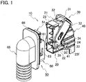
- a lever-type connector 10 includes a male connector 20 installed on a vehicle body panel 11 and a female connector 50 installed on the door 12.
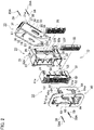
- the male connector 20 includes: a synthetic resin male housing (second housing) 21 that accommodates a plurality of male terminals 29 and that can be fitted to and removed from a female housing (first housing) 51 of the female connector 50; a synthetic resin lever 30 that is rotatably and slidably supported to the male housing 21 by support shafts 24, the lever 30 for engaging and disengaging the male housing 21 and the female housing 51 by a rotating operation; and a synthetic resin wire cover 40 that is mounted so as to cover a rear surface 22c of the male housing 21.
- a synthetic resin male housing (second housing) 21 that accommodates a plurality of male terminals 29 and that can be fitted to and removed from a female housing (first housing) 51 of the female connector 50
- a synthetic resin lever 30 that is rotatably and slidably supported to the male housing 21 by support shafts 24, the lever 30 for engaging and disengaging the male housing 21 and the female housing 51 by a rotating operation
- a synthetic resin wire cover 40 that is mounted so as to cover a rear surface 22
- the female connector 50 includes: the synthetic resin female housing (first housing) 51 that accommodates a plurality of female terminals 59 and that can be fitted to and removed from the male housing 21 of the male connector 20; a synthetic resin frame 60 having a rectangular frame and tubular shape that is fitted to the outer periphery of the female housing 51 and that is locked in a mounting hole 11a of the vehicle body panel 11; and a rubber grommet 65 attached to a flange portion 62 of the frame 60.
- the synthetic resin female housing (first housing) 51 that accommodates a plurality of female terminals 59 and that can be fitted to and removed from the male housing 21 of the male connector 20
- a synthetic resin frame 60 having a rectangular frame and tubular shape that is fitted to the outer periphery of the female housing 51 and that is locked in a mounting hole 11a of the vehicle body panel 11
- a rubber grommet 65 attached to a flange portion 62 of the frame 60.
- the male housing 21 includes: a rectangular block-shaped housing main body 22 having terminal receiving holes 22d for receiving the male terminals 29; and a hood portion 23 integrally and projectingly formed on the front side of the housing main body 22, the hood portion 23 into which the female housing 51 is fitted.
- Each of support shafts 24 extending in a direction perpendicular to the fitting direction is integrally and projectingly formed at a boundary between each of side surfaces 22a of the housing body 22 and a entral hood portion 23.
- An opening 22b is formed on one side surface 22a of the housing body 22.
- a first side retainer 25 for locking the male terminal 29 is fitted into the opening 22b.
- Each of guide protrusions 26 is integrally formed on a rear surface 22c side of each of the side surfaces 22a of the housing body 22 at a position near an operation portion 31 of the lever 30.
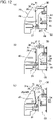
- Each of the guide protrusions 26 is provided closer to the operation portion 31 side of the lever 30 than the support shaft 24 side when the lever 30 is rotated, as illustrated in FIG. 12(c) .
- An apex 26a of each of the guide protrusions 26 is set to be inside the sliding portion 37 and the abutting portion 38 of the lever 30 in the vertical direction.
- Temporary locking recesses 27 and main locking recesses 28 are formed at positions corresponding to rotation loci of protrusions 39a of the locking arm 39 of the lever 30 on each of the side surfaces 22a of the hood portion 23 and the housing body 22.
- Each of locking portions 22f having a frame shape is integrally formed at a position near the main locking recess 28 on each side surface 22a of the housing body 22.
- the locking portions 22f locks locking protrusions 41 of the wire cover 40 that is mounted so as to cover the rear surface 22c side of the housing body 22.
- the lever 30 includes the operation portion 31 and a pair of arm portions 32 extending from respective side portions of the operation portion 31.
- Taper portions 31a are formed on the electric wire cover 40 side of the operation portion 31.
- the fitted male housing 21 and female housing 51 are assembled in the mounting hole 11a of the vehicle body panel 11.
- the lever 30 is slid to a normal position by the tapered portions 31a being pushed by the end surface of the mounting hole 11a. Whether the male housing 21 and the female housing 51 can be assembled to the vehicle body panel 11 is detected based on whether the lever 30 can slide.
- a bearing hole (bearing portion) 33 having a shaft sliding groove 34 in which the support shaft 24 slides is formed in the center of each of the arm portions 32.
- a pin-shaped cam follower 35 is integrally formed on each of the arm portions 32.
- An arc-shaped guide groove 36 with which the guide protrusion 26 engages is formed on each of the arm portions 32 at a portion between the operation portion 31 and the bearing hole 33.
- Each of the guide groove 36 is formed in an elongated arc shape centered on the support shaft 24.
- a pickup taper 36a for guiding the guide protrusion 26 is formed on the open end side of each of the guide grooves 36.
- each of the arm portions 32 is provided with a sliding portion 37 on which the guide protrusion 26 can slide in the sliding direction after the lever 30 is rotated.
- the sliding portion 37 is formed in a rail shape whose inside is recessed.
- Each of the arm portions 32 is provided with an abutting portion 38 with which the guide protrusion 26 abuts at the end of the slide after the lever 30 is rotated.
- a locking arm 39 that is elastically deformable in a direction perpendicular to the fitting direction is integrally formed on the outer side of the tip of each of the arm portions 32.
- the protrusion 39a provided on each of the locking arms 39 is configured to be able to be locked to and disengaged from the temporary locking recess 27 and the main locking recess 28 provided on each side surface 22 a of the male housing 21. That is, the locking arm 39 is also used for locking and unlocking the temporary locking recess 27 and the main locking recess 28 of the male housing 21.
- the female housing 51 is formed in a rectangular block shape and includes terminal accommodating chambers 52 in which the female terminals 59 are accommodated.
- terminal accommodating chambers 52 in which the female terminals 59 are accommodated.
- a release projection 53 for releasing temporary locking of the projection 39a of the locking arm 39 and the temporary locking recess 27 is integrally and protrudingly formed.
- An opening 54 is formed on one side surface 51 a of the female housing 51.
- a second side retainer 55 for locking the female terminal 59 is fitted into the opening 54.
- the frame 60 includes a rectangular tube-shaped frame body 61 having an open top surface and a frame plate-shaped flange portion 62 integrally formed with the frame body 61.
- a cam groove 63 with which the cam follower 35 of the lever 30 is engaged is formed on each side wall 61 a of the frame body 61.
- An elastically deformable panel locking arm 64 that is locked in the mounting hole 11a of the vehicle body panel 11 is integrally formed at a position of each side wall 61a of the frame body 61 near the flange portion 62.
- a peripheral edge of the mounting hole 11a of the vehicle body panel 11 is locked between the protrusion 64a of the panel locking arm 64 and the flange 62.
- the groove-shaped water stop portion 66 of the grommet 65 is fitted to the flange portion 62.
- an electric wire 29A is connected to each of the male terminals 29, and a wire harness W/H is constituted by a bundle of a plurality of electric wires 29A.
- An electric wire 59A is connected to each of the female terminals 59, and a bundle of a plurality of electric wires 59A constitutes a wire harness W/H.
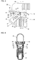
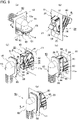
- the lever-type connector 10 when the lever-type connector 10 is assembled in the mounting hole 11 a of the vehicle body panel 11, first, as illustrated by an arrow A in FIG. 9(a) , the female connector 50 with the grommet 65 attached to the frame 60 is passed through a through hole 13a of a door panel 13. Then, as indicated by an arrow B in FIG. 9(b) , the male connector 20 with the lever 30 in the temporarily locked state is passed through the mounting hole 11a of the vehicle body panel 11. When the lever 30 is temporarily locked to the male housing 21, the protrusion 39a of the locking arm 39 of the lever 30 is temporarily locked in the temporary locking recess 27 of the male housing 21, as illustrated in FIGS.
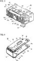
- the lever 30 is slid along the guide protrusion 26 of the male housing 21 by pushing in the operation portion 31 of the lever 30. Then, as illustrated in FIGS. 7 and 8 , the protrusion 39a of the locking arm 39 of the lever 30 is locked in the main locking recess 28 of the male housing 21.
- the shaft sliding groove 34 of the lever 30 makes sliding contact with the support shaft 24 of the male housing 21.
- the guide protrusion 26 of the male housing 21 is near the taper portion 31a of the operation portion 31 of the lever 30. Therefore, when the lever 30 is slid in the tilting direction with respect to the shaft sliding groove 34 of the lever 30 and the arc-shaped guide groove 36, a tilt suppressing effect is obtained. As a result, it is possible to reliably prevent damage to the support shaft 24 of the male housing 21 and the lever 30. Further, the guide protrusion 26 is provided in the vicinity of the operation portion 31, and is used (shared) for both rotation and slide of the lever 30. Therefore, it is possible to reduce the size and weight of the entire connector by suppressing the lever ratio.
- the top portion 26a of the guide protrusion 26 is set to be inward of the sliding portion 37 and the contact portion 38 of the lever 30 in the vertical direction, and does not protrude outward from the arm portion 32. Therefore, it is possible to reliably prevent the guide protrusion 26 from being damaged when it is assembled to the vehicle body by the lever 30 described later.
- the female connector 50 which has been completely operated by the operation portion 31 of the lever 30, is pushed into the mounting hole 11 a of the vehicle body panel 11.
- the protrusion 64a of the locking arm 64 provided on the frame 60 of the female connector 50 is locked to the peripheral edge of the mounting hole 11a of the vehicle body panel 11. Further, by holding the water stop portion 66 of the grommet 65 pressed against the vehicle body panel 11, it is possible to prevent water from entering the lever-type connector 10 through the mounting hole 11a of the vehicle body panel 11.
- the male housing 21 is provided with the support shaft 24, and the lever 30 is provided with the bearing portion 33 having the shaft sliding groove 34 in which the support shaft 24 slides.
- the lever 30 may be provided with a support shaft, and the male housing 21 may be provided with a bearing portion having a shaft sliding groove in which the support shaft slides.
- the cam follower 35 is provided on the lever 30 and the cam groove 63 with which the cam follower 35 is engaged is provided on the frame 60 of the female connector 50.
- a cam follower may be provided on the frame 60 of the female connector 50 or the female housing 51 and the lever 30 may be provided with a cam groove with which the cam follower engages.
- the male housing 21 is provided with the guide protrusion 26 and the lever 30 is provided with the guide groove 36 with which the guide protrusion 26 engages.
- the lever 30 is provided with a guide protrusion, and the male housing 21 or the wire cover 40 may be provided with a guide groove with which the guide protrusion engages.
- the female connector 50 is configured by the female housing 51 and the frame 60 having the flange portion 62 attached to the vehicle body panel 11 and the panel locking arm 64, and the cam groove 63 is formed in the frame 60.
- the female connector 50 may be configured by a female housing having a flange portion attached to the vehicle body panel 11 and a panel locking arm, and the cam groove may be formed in the female housing.
Landscapes
- Details Of Connecting Devices For Male And Female Coupling (AREA)
Claims (5)
- Hebel-Verbinder (10), der umfasst:einen ersten Verbinder (50), der ein erstes Gehäuse (51) sowie einen Rahmen (60) umfasst,einen zweiten Verbinder (20), der ein zweites Gehäuse (21) sowie einen Hebel (30) umfasst, wobei das zweite Gehäuse (21) an dem ersten Gehäuse (51) angebracht und von diesem entfernt werden kann;wobei der Hebel (30) an dem zweiten Gehäuse (21) drehbar gelagert ist, und der Hebel (30) zum Anbringen sowie Entfernen des ersten Gehäuses (51) und des zweiten Gehäuses (21) mittels einer Drehbetätigung dient;eine Tragewelle (24), die an dem zweiten Gehäuse (21) oder dem Hebel (30) vorhanden ist;ein Lagerungsabschnitt (33), der an dem anderen Element von dem zweiten Gehäuse (21) und dem Hebel (30) vorhanden ist, wobei der Lagerungsabschnitt (33) eine Wellen-Gleitnut (34) zum Gleiten der Tragewelle (24) umfasst;einen Nockenstößel (35), der an dem Hebel (30) oder dem ersten Gehäuse (51) vorhanden ist;eine Nockennut (63), die an dem anderen Element von dem Hebel (30) und dem ersten Gehäuse (51) vorhanden ist, wobei mit der Nockennut (63) der Nockenstößel (35) in Eingriff gebracht werden kann;einen Führungsvorsprung (26), der an dem Hebel (30) oder dem zweiten Gehäuse (21) vorhanden ist; sowieeine Führungsnut (36) mit einer Bogenform, die an dem anderen Element von dem Hebel (30) und dem zweiten Gehäuse (21) vorhanden ist, wobei mit der Führungsnut (36) der Führungsvorsprung (26) in Eingriff gebracht werden kann; undwenn sich der Hebel (30) in der Drehbetätigung befindet, der mit der Führungsnut (36) in Eingriff befindliche Führungsvorsprung (26) durch die Bogenform der Führungsnut (36) geführt wird,dadurch gekennzeichnet, dasswenn das erste Gehäuse (51) und das zweite Gehäuse (21) durch die Drehbetätigung des Hebels (30) vollständig in Passung gebracht werden, der Eingriff zwischen dem Führungsvorsprung (26) und der Führungsnut (36) gelöst wird und der Hebel (30) in Bezug auf das zweite Gehäuse (21) verschoben werden kann, indem die Tragewelle (24) in Gleitkontakt mit der Wellen-Gleitnut (34) kommt.
- Verfahren zum Montieren des Hebel-Verbinders (10) nach Anspruch 1 an einem Fahrzeug-Karosserieteil, wobei
wenn Herstellen von Passung des ersten Gehäuses (51) und des zweiten Gehäuses (21) abgeschlossen ist, Herstellen von Passung des ersten Verbinders (50) und des zweiten Verbinders (20), die in Passung sind, mit einem Fahrzeug-Karosserieteil (11) durchgeführt wird. - Verfahren zum Montieren des Hebel-Verbinders (10) nach Anspruch 2, wobeiein konischer Abschnitt (31a) an einem Betätigungsabschnitt (31) des Hebels (30) vorhanden ist, undwenn das erste Gehäuse (51) und das zweite Gehäuse (21), die in Passung sind, in einem Montageloch (11a) des Fahrzeug-Karosserieteils (11) montiert werden, der konische Abschnitt (31a) durch eine Endfläche des Montagelochs (11a) gedrückt wird, und der Hebel (30) an eine normale Position in Bezug auf das zweite Gehäuse (21) gleitet.
- Verfahren zum Montieren des Hebel-Verbinders (10) nach Anspruch 2 oder 3, wobei
ein Zustand, in dem der erste Verbinder (50) und der zweite Verbinder (20) an dem Fahrzeug-Karosserieteil (11) montiert werden können, basierend darauf erfasst wird, ob der Hebel (30) in Bezug auf den zweiten Verbinder (20) verschoben werden kann. - Verfahren zum Montieren des Hebel-Verbinders (10) nach einem der Ansprüche 2 bis 4, wobei
ein Passzustand des ersten Gehäuses (51) und des zweiten Gehäuses (21) basierend darauf erfasst wird, ob der erste Verbinder (50) und der zweite Verbinder (20), die in Passung sind, an dem Fahrzeug-Karosserieteil (11) montiert sind.
Applications Claiming Priority (2)
| Application Number | Priority Date | Filing Date | Title |
|---|---|---|---|
| JP2018153387 | 2018-08-17 | ||
| PCT/JP2019/031747 WO2020036152A1 (ja) | 2018-08-17 | 2019-08-09 | レバー式コネクタ |
Publications (3)
| Publication Number | Publication Date |
|---|---|
| EP3840133A1 EP3840133A1 (de) | 2021-06-23 |
| EP3840133A4 EP3840133A4 (de) | 2021-10-06 |
| EP3840133B1 true EP3840133B1 (de) | 2022-10-05 |
Family
ID=69525432
Family Applications (1)
| Application Number | Title | Priority Date | Filing Date |
|---|---|---|---|
| EP19850401.1A Active EP3840133B1 (de) | 2018-08-17 | 2019-08-09 | Hebelartiger anschluss |
Country Status (5)
| Country | Link |
|---|---|
| US (1) | US11482811B2 (de) |
| EP (1) | EP3840133B1 (de) |
| JP (1) | JP7145953B2 (de) |
| CN (1) | CN112470347B (de) |
| WO (1) | WO2020036152A1 (de) |
Families Citing this family (2)
| Publication number | Priority date | Publication date | Assignee | Title |
|---|---|---|---|---|
| JP1706310S (ja) * | 2021-06-18 | 2022-01-31 | 電気コネクタ用ハウジング | |
| EP4733848A1 (de) * | 2024-10-28 | 2026-04-29 | KYOCERA Document Solutions Inc. | Verbinderträgerstruktur und bilderzeugungsvorrichtung |
Family Cites Families (12)
| Publication number | Priority date | Publication date | Assignee | Title |
|---|---|---|---|---|
| JP3278048B2 (ja) * | 1997-10-01 | 2002-04-30 | 住友電装株式会社 | コネクタ |
| JP3820354B2 (ja) * | 2001-05-16 | 2006-09-13 | 矢崎総業株式会社 | レバー嵌合式電源回路遮断装置 |
| JP2002359037A (ja) | 2001-05-30 | 2002-12-13 | Sumitomo Wiring Syst Ltd | レバー式コネクタ |
| JP3644408B2 (ja) | 2001-05-30 | 2005-04-27 | 住友電装株式会社 | コネクタ |
| JP2003100382A (ja) * | 2001-09-25 | 2003-04-04 | Yazaki Corp | レバー嵌合式電源回路遮断装置 |
| JP3991670B2 (ja) * | 2001-12-06 | 2007-10-17 | 住友電装株式会社 | コネクタ |
| US6899554B1 (en) * | 2004-04-19 | 2005-05-31 | Jst Corporation | Dual action mechanical assisted connector |
| JP5747809B2 (ja) * | 2011-12-23 | 2015-07-15 | 住友電装株式会社 | レバー式コネクタ |
| JP5820289B2 (ja) * | 2012-02-08 | 2015-11-24 | 矢崎総業株式会社 | レバー式コネクタ |
| JP6020930B2 (ja) | 2013-09-30 | 2016-11-02 | 住友電装株式会社 | パネル取付型コネクタ |
| JP6402130B2 (ja) | 2015-05-15 | 2018-10-10 | 矢崎総業株式会社 | コネクタの接続構造 |
| JP6645359B2 (ja) | 2016-05-30 | 2020-02-14 | 住友電装株式会社 | コネクタ |
-
2019
- 2019-08-09 WO PCT/JP2019/031747 patent/WO2020036152A1/ja not_active Ceased
- 2019-08-09 EP EP19850401.1A patent/EP3840133B1/de active Active
- 2019-08-09 JP JP2020537077A patent/JP7145953B2/ja active Active
- 2019-08-09 CN CN201980049155.5A patent/CN112470347B/zh active Active
-
2021
- 2021-01-21 US US17/154,073 patent/US11482811B2/en active Active
Also Published As
| Publication number | Publication date |
|---|---|
| US20210143580A1 (en) | 2021-05-13 |
| JP7145953B2 (ja) | 2022-10-03 |
| CN112470347A (zh) | 2021-03-09 |
| EP3840133A1 (de) | 2021-06-23 |
| US11482811B2 (en) | 2022-10-25 |
| EP3840133A4 (de) | 2021-10-06 |
| WO2020036152A1 (ja) | 2020-02-20 |
| CN112470347B (zh) | 2023-02-17 |
| JPWO2020036152A1 (ja) | 2021-08-10 |
Similar Documents
| Publication | Publication Date | Title |
|---|---|---|
| KR101387278B1 (ko) | 커넥터 | |
| CA2600554C (en) | Lever mated connector assembly with a position assurance device | |
| US7300294B2 (en) | Connector and connector assembly of the movable member type | |
| US20040102077A1 (en) | Connector and a method of assembling it | |
| EP3764480B1 (de) | Hebelartiger anschluss | |
| US11189956B2 (en) | Liquid-tight movable connector | |
| JPH0778649A (ja) | パネル取付コネクタアセンブリ | |
| JP5939470B2 (ja) | コネクタ | |
| CN111834836B (zh) | 具有索环的连接器 | |
| WO2012104172A1 (en) | Plug-connector with cap-holding mechanism | |
| CN112436311B (zh) | 连接器 | |
| EP1056163B1 (de) | Elektrischer Verbinder mit Verschlüsselungssystem | |
| US11482811B2 (en) | Lever-type connector | |
| US20200059039A1 (en) | Lever type connector | |
| EP1049209B1 (de) | Steckverbinder mit Kontakthaltevorrichtung | |
| JP3494285B2 (ja) | コネクタ | |
| JP3856768B2 (ja) | コネクタ | |
| US20200059040A1 (en) | Lever type connector | |
| US20230084522A1 (en) | Connector | |
| CN112688105B (zh) | 连接器 | |
| US20200335897A1 (en) | Grommet-equipped connector | |
| WO2025169948A1 (ja) | コネクタ |
Legal Events
| Date | Code | Title | Description |
|---|---|---|---|
| STAA | Information on the status of an ep patent application or granted ep patent |
Free format text: STATUS: THE INTERNATIONAL PUBLICATION HAS BEEN MADE |
|
| PUAI | Public reference made under article 153(3) epc to a published international application that has entered the european phase |
Free format text: ORIGINAL CODE: 0009012 |
|
| STAA | Information on the status of an ep patent application or granted ep patent |
Free format text: STATUS: REQUEST FOR EXAMINATION WAS MADE |
|
| 17P | Request for examination filed |
Effective date: 20210119 |
|
| AK | Designated contracting states |
Kind code of ref document: A1 Designated state(s): AL AT BE BG CH CY CZ DE DK EE ES FI FR GB GR HR HU IE IS IT LI LT LU LV MC MK MT NL NO PL PT RO RS SE SI SK SM TR |
|
| A4 | Supplementary search report drawn up and despatched |
Effective date: 20210906 |
|
| RIC1 | Information provided on ipc code assigned before grant |
Ipc: H01R 13/64 20060101ALI20210831BHEP Ipc: H01R 13/629 20060101AFI20210831BHEP |
|
| DAV | Request for validation of the european patent (deleted) | ||
| DAX | Request for extension of the european patent (deleted) | ||
| STAA | Information on the status of an ep patent application or granted ep patent |
Free format text: STATUS: EXAMINATION IS IN PROGRESS |
|
| 17Q | First examination report despatched |
Effective date: 20220201 |
|
| GRAP | Despatch of communication of intention to grant a patent |
Free format text: ORIGINAL CODE: EPIDOSNIGR1 |
|
| STAA | Information on the status of an ep patent application or granted ep patent |
Free format text: STATUS: GRANT OF PATENT IS INTENDED |
|
| INTG | Intention to grant announced |
Effective date: 20220607 |
|
| GRAS | Grant fee paid |
Free format text: ORIGINAL CODE: EPIDOSNIGR3 |
|
| GRAA | (expected) grant |
Free format text: ORIGINAL CODE: 0009210 |
|
| STAA | Information on the status of an ep patent application or granted ep patent |
Free format text: STATUS: THE PATENT HAS BEEN GRANTED |
|
| AK | Designated contracting states |
Kind code of ref document: B1 Designated state(s): AL AT BE BG CH CY CZ DE DK EE ES FI FR GB GR HR HU IE IS IT LI LT LU LV MC MK MT NL NO PL PT RO RS SE SI SK SM TR |
|
| REG | Reference to a national code |
Ref country code: GB Ref legal event code: FG4D |
|
| REG | Reference to a national code |
Ref country code: CH Ref legal event code: EP |
|
| REG | Reference to a national code |
Ref country code: AT Ref legal event code: REF Ref document number: 1523347 Country of ref document: AT Kind code of ref document: T Effective date: 20221015 |
|
| REG | Reference to a national code |
Ref country code: IE Ref legal event code: FG4D |
|
| REG | Reference to a national code |
Ref country code: DE Ref legal event code: R096 Ref document number: 602019020391 Country of ref document: DE |
|
| REG | Reference to a national code |
Ref country code: LT Ref legal event code: MG9D |
|
| REG | Reference to a national code |
Ref country code: NL Ref legal event code: MP Effective date: 20221005 |
|
| REG | Reference to a national code |
Ref country code: AT Ref legal event code: MK05 Ref document number: 1523347 Country of ref document: AT Kind code of ref document: T Effective date: 20221005 |
|
| PG25 | Lapsed in a contracting state [announced via postgrant information from national office to epo] |
Ref country code: NL Free format text: LAPSE BECAUSE OF FAILURE TO SUBMIT A TRANSLATION OF THE DESCRIPTION OR TO PAY THE FEE WITHIN THE PRESCRIBED TIME-LIMIT Effective date: 20221005 |
|
| PG25 | Lapsed in a contracting state [announced via postgrant information from national office to epo] |
Ref country code: SE Free format text: LAPSE BECAUSE OF FAILURE TO SUBMIT A TRANSLATION OF THE DESCRIPTION OR TO PAY THE FEE WITHIN THE PRESCRIBED TIME-LIMIT Effective date: 20221005 Ref country code: PT Free format text: LAPSE BECAUSE OF FAILURE TO SUBMIT A TRANSLATION OF THE DESCRIPTION OR TO PAY THE FEE WITHIN THE PRESCRIBED TIME-LIMIT Effective date: 20230206 Ref country code: NO Free format text: LAPSE BECAUSE OF FAILURE TO SUBMIT A TRANSLATION OF THE DESCRIPTION OR TO PAY THE FEE WITHIN THE PRESCRIBED TIME-LIMIT Effective date: 20230105 Ref country code: LT Free format text: LAPSE BECAUSE OF FAILURE TO SUBMIT A TRANSLATION OF THE DESCRIPTION OR TO PAY THE FEE WITHIN THE PRESCRIBED TIME-LIMIT Effective date: 20221005 Ref country code: FI Free format text: LAPSE BECAUSE OF FAILURE TO SUBMIT A TRANSLATION OF THE DESCRIPTION OR TO PAY THE FEE WITHIN THE PRESCRIBED TIME-LIMIT Effective date: 20221005 Ref country code: ES Free format text: LAPSE BECAUSE OF FAILURE TO SUBMIT A TRANSLATION OF THE DESCRIPTION OR TO PAY THE FEE WITHIN THE PRESCRIBED TIME-LIMIT Effective date: 20221005 Ref country code: AT Free format text: LAPSE BECAUSE OF FAILURE TO SUBMIT A TRANSLATION OF THE DESCRIPTION OR TO PAY THE FEE WITHIN THE PRESCRIBED TIME-LIMIT Effective date: 20221005 |
|
| PG25 | Lapsed in a contracting state [announced via postgrant information from national office to epo] |
Ref country code: RS Free format text: LAPSE BECAUSE OF FAILURE TO SUBMIT A TRANSLATION OF THE DESCRIPTION OR TO PAY THE FEE WITHIN THE PRESCRIBED TIME-LIMIT Effective date: 20221005 Ref country code: PL Free format text: LAPSE BECAUSE OF FAILURE TO SUBMIT A TRANSLATION OF THE DESCRIPTION OR TO PAY THE FEE WITHIN THE PRESCRIBED TIME-LIMIT Effective date: 20221005 Ref country code: LV Free format text: LAPSE BECAUSE OF FAILURE TO SUBMIT A TRANSLATION OF THE DESCRIPTION OR TO PAY THE FEE WITHIN THE PRESCRIBED TIME-LIMIT Effective date: 20221005 Ref country code: IS Free format text: LAPSE BECAUSE OF FAILURE TO SUBMIT A TRANSLATION OF THE DESCRIPTION OR TO PAY THE FEE WITHIN THE PRESCRIBED TIME-LIMIT Effective date: 20230205 Ref country code: HR Free format text: LAPSE BECAUSE OF FAILURE TO SUBMIT A TRANSLATION OF THE DESCRIPTION OR TO PAY THE FEE WITHIN THE PRESCRIBED TIME-LIMIT Effective date: 20221005 Ref country code: GR Free format text: LAPSE BECAUSE OF FAILURE TO SUBMIT A TRANSLATION OF THE DESCRIPTION OR TO PAY THE FEE WITHIN THE PRESCRIBED TIME-LIMIT Effective date: 20230106 |
|
| REG | Reference to a national code |
Ref country code: DE Ref legal event code: R097 Ref document number: 602019020391 Country of ref document: DE |
|
| PG25 | Lapsed in a contracting state [announced via postgrant information from national office to epo] |
Ref country code: SM Free format text: LAPSE BECAUSE OF FAILURE TO SUBMIT A TRANSLATION OF THE DESCRIPTION OR TO PAY THE FEE WITHIN THE PRESCRIBED TIME-LIMIT Effective date: 20221005 Ref country code: RO Free format text: LAPSE BECAUSE OF FAILURE TO SUBMIT A TRANSLATION OF THE DESCRIPTION OR TO PAY THE FEE WITHIN THE PRESCRIBED TIME-LIMIT Effective date: 20221005 Ref country code: EE Free format text: LAPSE BECAUSE OF FAILURE TO SUBMIT A TRANSLATION OF THE DESCRIPTION OR TO PAY THE FEE WITHIN THE PRESCRIBED TIME-LIMIT Effective date: 20221005 Ref country code: DK Free format text: LAPSE BECAUSE OF FAILURE TO SUBMIT A TRANSLATION OF THE DESCRIPTION OR TO PAY THE FEE WITHIN THE PRESCRIBED TIME-LIMIT Effective date: 20221005 Ref country code: CZ Free format text: LAPSE BECAUSE OF FAILURE TO SUBMIT A TRANSLATION OF THE DESCRIPTION OR TO PAY THE FEE WITHIN THE PRESCRIBED TIME-LIMIT Effective date: 20221005 |
|
| PLBE | No opposition filed within time limit |
Free format text: ORIGINAL CODE: 0009261 |
|
| STAA | Information on the status of an ep patent application or granted ep patent |
Free format text: STATUS: NO OPPOSITION FILED WITHIN TIME LIMIT |
|
| PG25 | Lapsed in a contracting state [announced via postgrant information from national office to epo] |
Ref country code: SK Free format text: LAPSE BECAUSE OF FAILURE TO SUBMIT A TRANSLATION OF THE DESCRIPTION OR TO PAY THE FEE WITHIN THE PRESCRIBED TIME-LIMIT Effective date: 20221005 Ref country code: AL Free format text: LAPSE BECAUSE OF FAILURE TO SUBMIT A TRANSLATION OF THE DESCRIPTION OR TO PAY THE FEE WITHIN THE PRESCRIBED TIME-LIMIT Effective date: 20221005 |
|
| 26N | No opposition filed |
Effective date: 20230706 |
|
| PG25 | Lapsed in a contracting state [announced via postgrant information from national office to epo] |
Ref country code: SI Free format text: LAPSE BECAUSE OF FAILURE TO SUBMIT A TRANSLATION OF THE DESCRIPTION OR TO PAY THE FEE WITHIN THE PRESCRIBED TIME-LIMIT Effective date: 20221005 |
|
| PG25 | Lapsed in a contracting state [announced via postgrant information from national office to epo] |
Ref country code: MC Free format text: LAPSE BECAUSE OF FAILURE TO SUBMIT A TRANSLATION OF THE DESCRIPTION OR TO PAY THE FEE WITHIN THE PRESCRIBED TIME-LIMIT Effective date: 20221005 |
|
| REG | Reference to a national code |
Ref country code: CH Ref legal event code: PL |
|
| PG25 | Lapsed in a contracting state [announced via postgrant information from national office to epo] |
Ref country code: MC Free format text: LAPSE BECAUSE OF FAILURE TO SUBMIT A TRANSLATION OF THE DESCRIPTION OR TO PAY THE FEE WITHIN THE PRESCRIBED TIME-LIMIT Effective date: 20221005 |
|
| PG25 | Lapsed in a contracting state [announced via postgrant information from national office to epo] |
Ref country code: LU Free format text: LAPSE BECAUSE OF NON-PAYMENT OF DUE FEES Effective date: 20230809 |
|
| GBPC | Gb: european patent ceased through non-payment of renewal fee |
Effective date: 20230809 |
|
| PG25 | Lapsed in a contracting state [announced via postgrant information from national office to epo] |
Ref country code: LU Free format text: LAPSE BECAUSE OF NON-PAYMENT OF DUE FEES Effective date: 20230809 Ref country code: CH Free format text: LAPSE BECAUSE OF NON-PAYMENT OF DUE FEES Effective date: 20230831 |
|
| REG | Reference to a national code |
Ref country code: BE Ref legal event code: MM Effective date: 20230831 |
|
| REG | Reference to a national code |
Ref country code: IE Ref legal event code: MM4A |
|
| PG25 | Lapsed in a contracting state [announced via postgrant information from national office to epo] |
Ref country code: IT Free format text: LAPSE BECAUSE OF FAILURE TO SUBMIT A TRANSLATION OF THE DESCRIPTION OR TO PAY THE FEE WITHIN THE PRESCRIBED TIME-LIMIT Effective date: 20221005 |
|
| PG25 | Lapsed in a contracting state [announced via postgrant information from national office to epo] |
Ref country code: IE Free format text: LAPSE BECAUSE OF NON-PAYMENT OF DUE FEES Effective date: 20230809 |
|
| PG25 | Lapsed in a contracting state [announced via postgrant information from national office to epo] |
Ref country code: GB Free format text: LAPSE BECAUSE OF NON-PAYMENT OF DUE FEES Effective date: 20230809 |
|
| PG25 | Lapsed in a contracting state [announced via postgrant information from national office to epo] |
Ref country code: IE Free format text: LAPSE BECAUSE OF NON-PAYMENT OF DUE FEES Effective date: 20230809 Ref country code: GB Free format text: LAPSE BECAUSE OF NON-PAYMENT OF DUE FEES Effective date: 20230809 Ref country code: FR Free format text: LAPSE BECAUSE OF NON-PAYMENT OF DUE FEES Effective date: 20230831 |
|
| PG25 | Lapsed in a contracting state [announced via postgrant information from national office to epo] |
Ref country code: BE Free format text: LAPSE BECAUSE OF NON-PAYMENT OF DUE FEES Effective date: 20230831 |
|
| PG25 | Lapsed in a contracting state [announced via postgrant information from national office to epo] |
Ref country code: BG Free format text: LAPSE BECAUSE OF FAILURE TO SUBMIT A TRANSLATION OF THE DESCRIPTION OR TO PAY THE FEE WITHIN THE PRESCRIBED TIME-LIMIT Effective date: 20221005 |
|
| PG25 | Lapsed in a contracting state [announced via postgrant information from national office to epo] |
Ref country code: BG Free format text: LAPSE BECAUSE OF FAILURE TO SUBMIT A TRANSLATION OF THE DESCRIPTION OR TO PAY THE FEE WITHIN THE PRESCRIBED TIME-LIMIT Effective date: 20221005 |
|
| PG25 | Lapsed in a contracting state [announced via postgrant information from national office to epo] |
Ref country code: CY Free format text: LAPSE BECAUSE OF FAILURE TO SUBMIT A TRANSLATION OF THE DESCRIPTION OR TO PAY THE FEE WITHIN THE PRESCRIBED TIME-LIMIT; INVALID AB INITIO Effective date: 20190809 |
|
| PG25 | Lapsed in a contracting state [announced via postgrant information from national office to epo] |
Ref country code: HU Free format text: LAPSE BECAUSE OF FAILURE TO SUBMIT A TRANSLATION OF THE DESCRIPTION OR TO PAY THE FEE WITHIN THE PRESCRIBED TIME-LIMIT; INVALID AB INITIO Effective date: 20190809 |
|
| PGFP | Annual fee paid to national office [announced via postgrant information from national office to epo] |
Ref country code: DE Payment date: 20250702 Year of fee payment: 7 |
|
| PG25 | Lapsed in a contracting state [announced via postgrant information from national office to epo] |
Ref country code: TR Free format text: LAPSE BECAUSE OF FAILURE TO SUBMIT A TRANSLATION OF THE DESCRIPTION OR TO PAY THE FEE WITHIN THE PRESCRIBED TIME-LIMIT Effective date: 20221005 |