EP3840528A1 - Verfahren zum betrieb eines dampferzeugers, dampferzeuger und kochvorrichtung mit einem dampferzeuger - Google Patents
Verfahren zum betrieb eines dampferzeugers, dampferzeuger und kochvorrichtung mit einem dampferzeuger Download PDFInfo
- Publication number
- EP3840528A1 EP3840528A1 EP19216429.1A EP19216429A EP3840528A1 EP 3840528 A1 EP3840528 A1 EP 3840528A1 EP 19216429 A EP19216429 A EP 19216429A EP 3840528 A1 EP3840528 A1 EP 3840528A1
- Authority
- EP
- European Patent Office
- Prior art keywords
- temperature
- water
- heating device
- temperature detection
- filling
- Prior art date
- Legal status (The legal status is an assumption and is not a legal conclusion. Google has not performed a legal analysis and makes no representation as to the accuracy of the status listed.)
- Granted
Links
Images

Classifications
-
- H—ELECTRICITY
- H05—ELECTRIC TECHNIQUES NOT OTHERWISE PROVIDED FOR
- H05B—ELECTRIC HEATING; ELECTRIC LIGHT SOURCES NOT OTHERWISE PROVIDED FOR; CIRCUIT ARRANGEMENTS FOR ELECTRIC LIGHT SOURCES, IN GENERAL
- H05B1/00—Details of electric heating devices
- H05B1/02—Automatic switching arrangements specially adapted to apparatus ; Control of heating devices
- H05B1/0227—Applications
- H05B1/0252—Domestic applications
- H05B1/0258—For cooking
- H05B1/0269—For heating of fluids
-
- F—MECHANICAL ENGINEERING; LIGHTING; HEATING; WEAPONS; BLASTING
- F22—STEAM GENERATION
- F22B—METHODS OF STEAM GENERATION; STEAM BOILERS
- F22B1/00—Methods of steam generation characterised by form of heating method
- F22B1/28—Methods of steam generation characterised by form of heating method in boilers heated electrically
- F22B1/284—Methods of steam generation characterised by form of heating method in boilers heated electrically with water in reservoirs
-
- A—HUMAN NECESSITIES
- A47—FURNITURE; DOMESTIC ARTICLES OR APPLIANCES; COFFEE MILLS; SPICE MILLS; SUCTION CLEANERS IN GENERAL
- A47J—KITCHEN EQUIPMENT; COFFEE MILLS; SPICE MILLS; APPARATUS FOR MAKING BEVERAGES
- A47J27/00—Cooking-vessels
- A47J27/04—Cooking-vessels for cooking food in steam; Devices for extracting fruit juice by means of steam ; Vacuum cooking vessels
-
- A—HUMAN NECESSITIES
- A47—FURNITURE; DOMESTIC ARTICLES OR APPLIANCES; COFFEE MILLS; SPICE MILLS; SUCTION CLEANERS IN GENERAL
- A47J—KITCHEN EQUIPMENT; COFFEE MILLS; SPICE MILLS; APPARATUS FOR MAKING BEVERAGES
- A47J27/00—Cooking-vessels
- A47J27/14—Cooking-vessels for use in hotels, restaurants, or canteens
- A47J27/16—Cooking-vessels for use in hotels, restaurants, or canteens heated by steam
-
- A—HUMAN NECESSITIES
- A47—FURNITURE; DOMESTIC ARTICLES OR APPLIANCES; COFFEE MILLS; SPICE MILLS; SUCTION CLEANERS IN GENERAL
- A47J—KITCHEN EQUIPMENT; COFFEE MILLS; SPICE MILLS; APPARATUS FOR MAKING BEVERAGES
- A47J36/00—Parts, details or accessories of cooking-vessels
-
- A—HUMAN NECESSITIES
- A47—FURNITURE; DOMESTIC ARTICLES OR APPLIANCES; COFFEE MILLS; SPICE MILLS; SUCTION CLEANERS IN GENERAL
- A47J—KITCHEN EQUIPMENT; COFFEE MILLS; SPICE MILLS; APPARATUS FOR MAKING BEVERAGES
- A47J36/00—Parts, details or accessories of cooking-vessels
- A47J36/32—Time-controlled igniting mechanisms or alarm devices
-
- F—MECHANICAL ENGINEERING; LIGHTING; HEATING; WEAPONS; BLASTING
- F22—STEAM GENERATION
- F22B—METHODS OF STEAM GENERATION; STEAM BOILERS
- F22B1/00—Methods of steam generation characterised by form of heating method
- F22B1/28—Methods of steam generation characterised by form of heating method in boilers heated electrically
- F22B1/284—Methods of steam generation characterised by form of heating method in boilers heated electrically with water in reservoirs
- F22B1/285—Methods of steam generation characterised by form of heating method in boilers heated electrically with water in reservoirs the water being fed by a pump to the reservoirs
-
- F—MECHANICAL ENGINEERING; LIGHTING; HEATING; WEAPONS; BLASTING
- F22—STEAM GENERATION
- F22B—METHODS OF STEAM GENERATION; STEAM BOILERS
- F22B35/00—Control systems for steam boilers
-
- F—MECHANICAL ENGINEERING; LIGHTING; HEATING; WEAPONS; BLASTING
- F22—STEAM GENERATION
- F22D—PREHEATING, OR ACCUMULATING PREHEATED, FEED-WATER FOR STEAM GENERATION; FEED-WATER SUPPLY FOR STEAM GENERATION; CONTROLLING WATER LEVEL FOR STEAM GENERATION; AUXILIARY DEVICES FOR PROMOTING WATER CIRCULATION WITHIN STEAM BOILERS
- F22D5/00—Controlling water feed or water level; Automatic water feeding or water-level regulators
- F22D5/26—Automatic feed-control systems
-
- F—MECHANICAL ENGINEERING; LIGHTING; HEATING; WEAPONS; BLASTING
- F24—HEATING; RANGES; VENTILATING
- F24C—DOMESTIC STOVES OR RANGES ; DETAILS OF DOMESTIC STOVES OR RANGES, OF GENERAL APPLICATION
- F24C15/00—Details
- F24C15/32—Arrangements of ducts for hot gases, e.g. in or around baking ovens
- F24C15/322—Arrangements of ducts for hot gases, e.g. in or around baking ovens with forced circulation
- F24C15/327—Arrangements of ducts for hot gases, e.g. in or around baking ovens with forced circulation with air moisturising
-
- A—HUMAN NECESSITIES
- A47—FURNITURE; DOMESTIC ARTICLES OR APPLIANCES; COFFEE MILLS; SPICE MILLS; SUCTION CLEANERS IN GENERAL
- A47J—KITCHEN EQUIPMENT; COFFEE MILLS; SPICE MILLS; APPARATUS FOR MAKING BEVERAGES
- A47J27/00—Cooking-vessels
- A47J27/04—Cooking-vessels for cooking food in steam; Devices for extracting fruit juice by means of steam ; Vacuum cooking vessels
- A47J2027/043—Cooking-vessels for cooking food in steam; Devices for extracting fruit juice by means of steam ; Vacuum cooking vessels for cooking food in steam
-
- F—MECHANICAL ENGINEERING; LIGHTING; HEATING; WEAPONS; BLASTING
- F22—STEAM GENERATION
- F22B—METHODS OF STEAM GENERATION; STEAM BOILERS
- F22B37/00—Component parts or details of steam boilers
- F22B37/78—Adaptations or mounting of level indicators
Definitions
- the invention is directed to a method of operating a steam generator, in particular in a cooking device or a household device operating with steam. Furthermore, the invention is directed to such a steam generator as well as to a cooking device with such a steam generator.
- Steam generators for cooking devices for cooking purposes or the like are known for example from EP 2 366 315 B1 or EP 2 397 755 B1 .
- a challenge with these steam generators is how to find a way to start the generation of steam with the steam generator as fast as possible, in order to be able to start operation of the household device quickly.
- the object of the invention is to provide a method of operating a steam generator as well as such a steam generator and a cooking device with such a steam generator with which problems of the prior art can be avoided and, in particular, it is possible to speed up operating a steam generator and a household device provided with it.
- the steam generator comprises a water container, two heating devices on the water container, in particular applied to an outside thereof.
- the two heating devices are located separated from each other in different height regions viewed in vertical direction.
- One heating device is an upper heating device and the other heating device is a lower heating device. More separate heating devices could be provided.
- a flat first temperature detection device is provided and covers a temperature detection area. This temperature detection area includes at least the area covered by the heating devices, preferably also a surface of the water container between the heating devices. It can even be overlapping over the heating devices onto the outer surface of the water container or its lateral wall, respectively.
- the first temperature detection device can comprise a temperature sensitive layer, preferably a dielectrical isolation layer.
- At least one second temperature detection device in the form of a spot-like temperature sensor is provided, being located on the water container in a region of an upper border of the upper heating device or slightly above the upper heating device, respectively.
- a control device for evaluating the first temperature detection device and the second temperature detection device and for activating and deactivating the two heating devices is provided, preferably comprising a microcontroller.
- the control device can be for the steam generator alone or be provided for the whole cooking device.
- the method comprises the steps of at first filling the water container with water, which is being made for a predefined first filling duration D 1 , for example 10 sec to 30 sec. After this first filling duration D 1 has elapsed, the lower heating device is activated, and the upper heating device stays deactivated. The water container is still continuously filled further with water. In case the first temperature detection device detects a temperature exceeding a first predefined temperature threshold T thr , the lower heating device is deactivated again, wherein the water container is still further filled with water. So the water container is continuously filled with water.
- the lower heating device is activated again. This may be tried for two or three times until the first temperature detection device does not detect any temperature above the first temperature threshold T thr for a duration of at least 5 sec, in particular at least 10 sec. Then the control device defines the quantity of water in the water container to have a level I 2 , which is as high as 60% to 90% of a height of an upper rim of the lower heating device so that it is covered sufficiently by water to be activated continuously. Filling of the water container is continued, but now the steam generator does already generate steam, the steam generating having started preferably about 10 sec or 20 sec after the first temperature threshold T thr has been reached for the first time.
- the second temperature detection device detects a temperature of at least 95°C, preferably at least 95°C for a time of more than 3 sec, which may mean that the temperature is from now on constantly above 95°C
- the upper heating device and the lower heating device are both activated for heating operation.
- This temperature of at least 95°C can be taken as a sign that now a sufficient amount of water is inside the water container not to cover the upper heating device, but to have sufficient steam or splashing water on the inside of the water container to absorb sufficient heat of the upper heating device that this heat can help for a fast steam generation, whereas the first threshold temperature T thr is not reached too fast for the upper heating device to be deactivated again after only 2 sec to 5 sec.
- the filling of water into the water container can be continued even further in an embodiment of the invention with the upper heating device being activated, wherein this filling may only be stopped when the first temperature detection device does not detect a temperature above the first temperature threshold T thr for a second time for a second duration D 2 of between 5 sec to 10 sec after the time before. This is then taken as a sign that now the water level is high enough to cover most part of the upper heating device so that the first temperature threshold T thr is not reached by the heating operation of the upper heating device.
- the first temperature detection device detects a temperature above the first temperature threshold T thr after the upper heating device has been activated, only the upper heating device is deactivated.
- the water level at first falls below the level that is needed for a stable operation of the upper heating device, and only later on below the level that is needed for a stable operation of the lower heating device.
- the lower heating device can also be deactivated if the first temperature detection device again detects a temperature above the first temperature threshold T thr after 2 sec to 5 sec after deactivating the upper heating device. Even if this is not very probable in a regular operation of the steam generator, it can be a reasonable measure.
- a filling rate of filling water into the water container is not known. If the duration after having started filling the water container until the second temperature detection device detects a temperature of above at least 95°C is less than a predefined filling duration threshold D 3 , a filling rate can be reduced by at least 5%, preferably by at least 20%. This is then a sign that the filling with water takes place faster than expected. The reduction may be made by clocking a pumping action of a water pump filling water into the water container with the filling rate being the pump filling rate. Alternatively, a valve for filling water may be partly closed to reduce the flow of water through it.
- the upper heating device is deactivated for at least 3 sec after the filling the water container has been stopped for the first time, if the first temperature detection device detects a temperature above the first device threshold T thr . This is a sign that the upper heating device has generated too much heat. More water is then filled into the water container, which will cool it down and absorb more heat generated by the upper heating device, and the upper heating device is then activated again.
- the lower heating device and the upper heating device are both activated simultaneously and together for a high rate of steam generation. They can be activated with their maximum power, wherein preferably they only can be activated with one single power rate.
- a signal for stopping or starting to fill water into the water container can be generated by monitoring the first derivation by time of a temperature signal of the first temperature detection device. This allows for an easier detection of surpassing any given or predefined value.
- the temperature detected by the first temperature detection device is monitored and a predefined duration is measured until the lower heating device has not been deactivated by a temperature signal of the first temperature detection device for at least 5 sec.
- a temperature signal of the first temperature detection device The time is measured until a lower heating device has not been deactivated for at least 5 sec, and then a measured filling rate FR m is determined by dividing a known water volume being defined by the location of the lower heating device on the water container by the time that has elapsed when the lower heating device has been activated or has not been deactivated.
- the measured filling rate FR m is compared with a predefined filling rate FR d which is known for this steam generator. If the measured filling rate FR m is more than 10% below the predefined filling rate FR d , it is determined that a calcification of the filling pump or of a filling valve is too high and a decalcification must be made because the filling rate is too low. Preferably a signal can be output for a user to execute such a decalcification process of the filling pump or that a repair must be made. Such a measured filling rate FR m can be even 20%, 30% or 40% below the predefined filling rate FR d for this action to take place.
- control device can take an increased calcification as a trigger to start and/or stop filling the water container with water with a delay, preferably a delay of 3 sec to 10 sec. This takes the reduced filling rate into account.
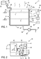
- a steam generator 11 according to the invention is shown, the steam generator 11 having a water container 12 which advantageously is in the form of a vertical or upright round-cylindrical container.
- Water container 12 has a circumferential lateral wall 13 and a base plate 14, which are connected in watertight manner.
- Lateral wall 13 is made of metal, preferably of stainless steel.
- Base plate 14 can also be made of the same material, alternatively from synthetic material being connected in watertight manner to the lateral wall 13.
- cover or lid for collecting or concentrating steam S might be provided, for example as known from DE 10 2016 214 283 A1 . This is, however, not important for the invention.
- the steam S can rise from the water container 12 and be guided in a steam channel or the like to the location of its application. This is described later in Fig. 2 .
- Dielectric isolation 16 preferably contains glass or glass ceramic and can be fabricated preferably according to DE 10 2013 200 277 A1 or WO 2007/136268 A1 . It is only important that the material of this dielectric isolation 16 is adapted so as to change its resistance behavior strongly at the temperature threshold mentioned before, which is preferably a temperature between 150°C and 300°C.
- An upper heating element 18 is applied onto the dielectric isolation 16 as shown here, which is also denominated by heat 1.
- the upper heating element 18 may be applied in meandering form or in the form of several parallel stripes or in form of a closed area layout running around the water container 12 or having a circumferential layout, respectively. This is but known from the prior art as mentioned before, for example according to DE 10 2015 218 121 A1 . It is preferably a thick film heating element.
- a lower heating element 20 is applied on the outside of lateral wall 13 directly onto the dielectric isolation 16.
- the lower heating element 20 is also denominated by heat 2, and is basically in a shape or form similar to the upper heating element 18, preferably also according to DE 10 2015 218 121 A1 . It is important that the upper heating element 18 is located above the lower heating element 20 in vertical direction, which direction in this case is extended from base plate 14 at right angle upwards, which is also the direction that the steam S is taking which rises from water W in the water container 12.
- There is a distancing ring region 21 between the two heating elements 18 and 20 which is ring-like or runs circumferentially around water container 12. The width of the ring region 21 may be between 5 mm and 20 mm.
- the heating elements 18 and 20 correspond to the heating devices described before. Both heating elements can have an electrical power of 750 W.
- the upper heating element 18 is activated by a switch 27 with which it is connected, wherein switch 27 preferably is connected to an energy source, for example a mains connection of the steam generator 11. This is not shown here, but can easily be conceived by a person skilled in the art.
- the lower heating element 20 is connected to a switch 28 which is also connected to the same energy source.
- the switches 27 and 28 are controlled by a control 25 which is the control for the whole steam generator 11, preferably also for a corresponding steam cooking device according to Fig. 2 .
- Control 25 is also connected with a connection 17 to the lateral wall 13 of the water container 12 to measure a leakage current as explained before from one of the heating elements 18 and 20 through the dielectric isolation 16.
- a measuring apparatus 26 connected to the control 25 can measure the leakage current through the dielectric isolation16.
- WO 2007/136268 A1 and DE 10 2013 200 277 A1 named before, which is easy for the person skilled in the art to conceive and to put into practice.
- An upper temperature sensor 22a is provided on the outside of lateral wall 13, in this case also on the dielectric isolation 16 and slightly above the upper heating element 18 in the vertical direction.
- a lower temperature sensor 22b is placed between the upper heating element 18 and the lower heating element 20 in the ring region 21, preferably also placed onto the dielectric isolation 16. This is mainly for the reason so that there is sufficient electrical isolation to the metallic lateral wall 13 of the water container 12.
- the temperature sensors 22a and 22b can be made for point-like temperature detection, for example as NTC temperature sensors in SMD construction manner. They should be attached with a good thermal contact to the lateral wall 13 so as to detect its temperature or the temperature of water W inside the water container 12 and potentially being right on the other side of the lateral wall 13. Temperature sensors 22a and 22b are also connected to the control 25 for evaluation.
- a fresh water tank 30 For filling water W into the water container 12, a fresh water tank 30 is provided which can also be a connection to a fresh water pipe. By activating a filling pump 31, alternatively opening a valve, water W from the fresh water tank 30 can be pumped into the water container 12, for example until a water level I is reached as is shown here, which is for example about slightly higher than a middle region of the upper heating element 18, but below temperature sensor 22a. This is a water level that can be regarded as very good for generating steam with a high rate with high heating power.
- a lower water level I 2 is a water level at which, when it is reached and surpassed by water W, the heat generated by the lower heating element 20 in its activation state is absorbed by the water W.
- the temperature stays beneath a critical temperature T thr . So the first temperature detection device with the dielectric isolation 16 does not lose its isolating properties, in consequence no leakage current can be measured. If the water level I is beneath lower water level I 2 , the heat of the lower heating element 20 is not sufficiently absorbed, the temperature rises and reaches the critical temperature T thr . So a small leakage current starts to flow from the lower heating element 20 through the dielectric isolation 16 to the metallic lateral wall 13 where it can be detected. When the critical temperature T thr is surpassed, the leakage current has reached a critical value and a critical temperature is detected by control 25 and measuring apparatus 26. In consequence, the lower heating element 20 is deactivated; the upper heating element 18 has not even been active.
- an upper water level I 1 is a water level at which, when it is reached and surpassed by water W, the heat generated by the upper heating element 18 in its activation state is absorbed by the water W.
- the temperature stays beneath a critical temperature T thr . In the region of the lower heating element 20 the temperature will most probably not surpass 100°C for all the heat is absorbed by water W. So the first temperature detection device with the dielectric isolation 16 does not lose its isolating properties, in consequence no leakage current can be measured. If, however, the water level I is beneath upper water level I 1 , the heat of the upper heating element 18 is not absorbed sufficiently, and the same as described before will happen. So if the water level I is above the upper water level I 1 , the steam generator can be operating with both heating elements 18 and 20 activated and without overheat problems.
- a water outlet 34 leads via an outlet pipe 36 to an outlet pump 37.
- the outlet pump 37 leads to an outlet 38 which may be a waste water outlet into a sewage.
- the outlet pump 37 is also connected to control 25 and is controlled by control 25.
- a steam cooking device 40 is shown schematically which has a housing 41 and a cooking chamber 43 inside the housing 41.
- the cooking chamber 43 can be closed with a chamber door 44.
- food 46 can be placed for being cooking with the help of hot steam.
- a ventilator 48 is provided for transporting steam through a steam channel 49 from the steam generator 11 with water W in the water container, wherein the steam S is blown into the cooking chamber 43 in known manner.
- control 25 is provided for the whole steam cooking device 40.
- the fresh water tank 30 is provided inside the steam cooking device 40 and is connected via a fresh water pipe 32 and filling pump 31 to the steam generator 11 or its water container 12, respectively.
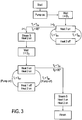
- the filling pump 31 is activated in the second step and starts pumping water W from the fresh water tank 30 into the water container 12.
- a filling rate FR of this filling process may not be known, which is due to the fact that the parameters of integrating the steam generator 11 and fresh water tank 30 with fresh water pipe 32 and a valve or the filling pump 31 may not be known to the manufacturer of the steam generator 11.
- water level sensors directly reacting to a level of water shall be avoided according to the invention.
- D 1 which may be, for example, for 10 sec up to 20 sec.
- the upper heating element 18 stays deactivated, whereas the lower heating element 20 is being activated and Heat 2 is on. If the water level until this moment has not yet reached the level I 2 , the temperature at the lower heating element 20 will quickly rise as its heat cannot be sufficiently absorbed by water W inside the water container 12. So for example after 5 sec to 8 sec after activating the lower heating element 20, the first temperature detection device detects that a temperature T 1 has reached and surpassed the first temperature threshold T thr .
- this critical temperature must be somewhere in the region of the lower heating element 20. So it is deactivated again and Heat 2 is also off, see the fourth step. Then the temperature will sink beneath the first temperature threshold T thr , and according to step 5 the lower heating element 20 is activated again. If now for a time t of more than 6 sec the temperature T 1 does not reach and surpass the first temperature threshold T thr , this can be taken as a sign that now, as water has still been continuously filled into the water container 12, a water level I has reached and surpassed the water level I 2 . If, on the other hand, after less than 6 sec or 5 sec the critical temperature of T 1 is reached and surpassed again, the same cycle will be started all over. As water is continuously filled or pumped into the water container 12, the water level I will continuously rise until the water level I 2 has been reached.
- the quantity of water W in water container 12 is sufficiently high to continuously operate the lower heating element 20, which will heat the water W up to the boiling point to generate steam S for the operation of the steam cooking device 40, this generation of steam took place rather quick, as obviously only a relatively small quantity of water had to be heated. If the quantity of water would be even less, the lower heating element 20 would have been deactivated more often, which may be taking place for a few times, whereas even during this phase the lower heating element 20 has been active for short periods of time.
- step 6 when heating only takes place with lower heating element 20, and still water W is continuously filled or pumped into the water container 12, which is also being heated for generating steam, this hot or boiling water reaches with its heat the upper temperature sensor 22a.
- the temperature of the upper temperature sensor 22a is monitored by the control 25, and as soon as it reaches a temperature of about 95°C, the water level I will have reached the level I 1 , which is shown in fig. 5 . From fig. 5 it can be taken that the level I 1 is somewhat beneath the position of the upper temperature sensor 22a.
- the upper heating element 18 can be activated. It is possible to wait for a short time, preferably 2 sec to 4 sec, for example 3 sec, after first detecting a temperature T 2 of more than 95°C at the upper temperature sensor 22a, until the upper heating element 18 is activated.
- the lower heating element 20 already is active, so Heat 1 is on and Heat 2 is on according to step 7. For safety reasons it is checked by monitoring the first temperature detection device whether after a few seconds, for example after a second duration D 2 between 5 sec to 10 sec, and whether after activating the upper heating element 18 the temperature T 1 reaches and surpasses the first temperature threshold T thr .
- a pumping of fresh water W into the water container 12 can be stopped after the upper heating element 18 has not been turned off due to a temperature surpassing the first temperature threshold T thr for 10 sec or 20 sec, for example. If, after that, the temperature T 1 again reaches the first temperature threshold T thr , this means that the water level I has fallen beneath the upper water level I 1 and fresh water W has to be filled in again. This is being done according to the last steps of the flow diagram of Fig. 3 .
- This operation can continue as long as steam S is required, and as long as this steam should be generated with a high steam generating rate.
- the filling pump 31 can be active until the temperature measured by the first temperature detection device has reached an absolute value that has been detected 2 sec to 20 sec, for example 5 sec to 10 sec, before the significant rise of the first derivation by time of the temperature signal T 1 has been detected.
- the lower temperature sensor 22b can also be used, in particular if only the lower heating element 20 shall be operated for a lower rate of steam generation.
- the temperature measured by the second temperature sensor 22b is a good indicator whether the water level I of water W inside the water container 12 has reached its height or is still below. If the water level I has surpassed the second temperature sensor 22b, its temperature will constantly be about 100°C, which can be used as a sign that now or maybe 10 sec to 20 sec afterwards, the filling pump 31 can stop filling water W into the water container 12.
- a filling rate of the filling pump 31 can be done for example by measuring the time until the water level I 2 has been reached or even until the upper water level I 1 has been reached. Up to this upper water level I 1 , the filling pump 31 has continuously pumped fresh water W into the water container 12 that has been empty before. Of course, some water has already been evaporated as steam S from the water container 12 by heating with the lower heating element 20, partly also by heating with the upper heating element 18. This quantity of water W evaporated as steam S is, however, neglected for a rough determination of the filling rate.
- the quantity of water corresponding to water level I 1 and water level I 2 is known in control 25.
- the filling rate can then simply be calculated by dividing the known quantity al level I 1 or level I 2 by the time needed to reach this water level.
- the time of activation of the heating elements can be taken into account, and from experiments their steaming rate can be known. From the two parameters a steaming rate can be calculated, which results in an amount of water evaporated by the heating elements. This amount of water has to be added to the water quantity mentioned before as a correction of the calculation for the filling rate, and this sum is then divided by the time needed to reach the corresponding water level.
Landscapes
- Engineering & Computer Science (AREA)
- Food Science & Technology (AREA)
- Mechanical Engineering (AREA)
- General Engineering & Computer Science (AREA)
- Physics & Mathematics (AREA)
- Thermal Sciences (AREA)
- Life Sciences & Earth Sciences (AREA)
- Sustainable Development (AREA)
- Sustainable Energy (AREA)
- Chemical & Material Sciences (AREA)
- Combustion & Propulsion (AREA)
- Cookers (AREA)
- Commercial Cooking Devices (AREA)
Priority Applications (5)
| Application Number | Priority Date | Filing Date | Title |
|---|---|---|---|
| PL19216429.1T PL3840528T3 (pl) | 2019-12-16 | 2019-12-16 | Sposób działania wytwornicy pary, wytwornica pary i urządzenie do gotowania z wytwornicą pary |
| EP19216429.1A EP3840528B1 (de) | 2019-12-16 | 2019-12-16 | Verfahren zum betrieb eines dampferzeugers, dampferzeuger und kochvorrichtung mit einem dampferzeuger |
| US16/952,430 US11980314B2 (en) | 2019-12-16 | 2020-11-19 | Method of operating a steam generator, steam generator and cooking device with a steam generator |
| KR1020200175791A KR102948504B1 (ko) | 2019-12-16 | 2020-12-15 | 증기 발생기를 작동시키는 방법, 증기 발생기 및 증기 발생기를 갖는 조리 장치 |
| CN202011489705.6A CN112971516B (zh) | 2019-12-16 | 2020-12-16 | 操作蒸汽发生器的方法、蒸汽发生器和具有蒸汽发生器的烹饪装置 |
Applications Claiming Priority (1)
| Application Number | Priority Date | Filing Date | Title |
|---|---|---|---|
| EP19216429.1A EP3840528B1 (de) | 2019-12-16 | 2019-12-16 | Verfahren zum betrieb eines dampferzeugers, dampferzeuger und kochvorrichtung mit einem dampferzeuger |
Publications (2)
| Publication Number | Publication Date |
|---|---|
| EP3840528A1 true EP3840528A1 (de) | 2021-06-23 |
| EP3840528B1 EP3840528B1 (de) | 2022-10-12 |
Family
ID=68917535
Family Applications (1)
| Application Number | Title | Priority Date | Filing Date |
|---|---|---|---|
| EP19216429.1A Active EP3840528B1 (de) | 2019-12-16 | 2019-12-16 | Verfahren zum betrieb eines dampferzeugers, dampferzeuger und kochvorrichtung mit einem dampferzeuger |
Country Status (5)
| Country | Link |
|---|---|
| US (1) | US11980314B2 (de) |
| EP (1) | EP3840528B1 (de) |
| KR (1) | KR102948504B1 (de) |
| CN (1) | CN112971516B (de) |
| PL (1) | PL3840528T3 (de) |
Cited By (3)
| Publication number | Priority date | Publication date | Assignee | Title |
|---|---|---|---|---|
| EP4382811A1 (de) | 2022-12-09 | 2024-06-12 | E.G.O. Elektro-Gerätebau GmbH | Vorrichtung zur dampferzeugung und wasserführendes haushaltsgerät mit einer solchen vorrichtung |
| EP4464231A1 (de) | 2023-05-16 | 2024-11-20 | E.G.O. Elektro-Gerätebau GmbH | Heizeinrichtung, pumpe mit einer solchen heizeinrichtung und wasserführendes haushaltsgerät |
| EP4474702A1 (de) * | 2023-05-17 | 2024-12-11 | E.G.O. Elektro-Gerätebau GmbH | Heizvorrichtung zum erhitzen und verdampfen von wasser und wasserführendes haushaltsgerät mit einer solchen heizvorrichtung |
Families Citing this family (1)
| Publication number | Priority date | Publication date | Assignee | Title |
|---|---|---|---|---|
| CN116998918A (zh) * | 2023-07-28 | 2023-11-07 | 浙江比依电器股份有限公司 | 空气炸锅的智能缺水检测与管控方法及装置 |
Citations (9)
| Publication number | Priority date | Publication date | Assignee | Title |
|---|---|---|---|---|
| WO2007136268A1 (en) | 2006-05-23 | 2007-11-29 | Ferro Techniek Holding B.V. | Electric heating device with temperature detection through dielectric layer |
| US20090107477A1 (en) * | 2007-10-26 | 2009-04-30 | Premark Feg L.L.C. | Steam Oven System with Steam Generator |
| DE102013200277A1 (de) | 2013-01-10 | 2014-01-30 | E.G.O. Elektro-Gerätebau GmbH | Heizeinrichtung und Verfahren zur Temperaturmessung an der Heizeinrichtung |
| EP2366315B1 (de) | 2009-12-22 | 2016-03-16 | BSH Hausgeräte GmbH | Dampferzeugungssystem für ein Haushaltsgerät und Verfahren zum Betreiben eines Dampferzeugungssystems |
| EP2397755B1 (de) | 2009-03-05 | 2016-10-19 | Artweger GmbH & Co. KG | Dampfgenerator mit unterbrechungsfreiem Dampfen und sicherer Entleerung |
| EP3088800A1 (de) * | 2015-04-21 | 2016-11-02 | E.G.O. ELEKTRO-GERÄTEBAU GmbH | Heizeinrichtung zum erhitzen von flüssigkeiten, verdampfer für ein elektrogargerät und verfahren zum betrieb einer heizeinrichtung |
| DE102015218121A1 (de) | 2015-09-21 | 2017-03-23 | E.G.O. Elektro-Gerätebau GmbH | Heizeinrichtung zum Erhitzen von Wasser und Verfahren zum Betrieb einer solchen Heizeinrichtung |
| EP3278691A1 (de) * | 2016-08-02 | 2018-02-07 | E.G.O. ELEKTRO-GERÄTEBAU GmbH | Verdampfereinrichtung für wasser und gargerät mit einer solchen verdampfereinrichtung |
| US20180264374A1 (en) * | 2015-09-28 | 2018-09-20 | Commissariat A L'energie Atomique Et Aux Energies Alternatives | Device For Converting A Liquid Into Vapour And Associated Method For Regulating A Heating Power |
Family Cites Families (17)
| Publication number | Priority date | Publication date | Assignee | Title |
|---|---|---|---|---|
| CH662924A5 (de) * | 1985-01-21 | 1987-11-13 | Wuest Ernst Menu System | Daempfer. |
| US5158064A (en) * | 1991-05-13 | 1992-10-27 | Willis Thomas J | Steam drying element for steam cooking device |
| DE19638664A1 (de) | 1996-09-20 | 1998-03-26 | Bosch Siemens Hausgeraete | Gargerät mit im Garraum abstellbarem Garbehältnis zum Dampfgaren |
| KR20050026603A (ko) * | 2003-09-09 | 2005-03-15 | 삼성전자주식회사 | 과열증기 조리장치 |
| JP2006230433A (ja) | 2005-02-22 | 2006-09-07 | Matsushita Electric Ind Co Ltd | 炊飯器 |
| KR100667203B1 (ko) | 2005-05-16 | 2007-01-12 | 삼성전자주식회사 | 증기조리장치 및 그 히터 제어 방법 |
| JP4728180B2 (ja) * | 2006-06-28 | 2011-07-20 | シャープ株式会社 | 加熱調理器用の蒸気発生装置および加熱調理器 |
| DE102007029244A1 (de) * | 2007-06-14 | 2008-12-24 | E.G.O. Elektro-Gerätebau GmbH | Dampferzeuger, Garvorrichtung, Verfahren zum Betrieb beziehungsweise zur Herstellung eines Dampferzeugers sowie Verfahren zum Kühlen einer Heizvorrichtung |
| KR101000803B1 (ko) * | 2010-01-28 | 2010-12-13 | 오문근 | 과열증기를 이용한 조리기구 |
| KR101204032B1 (ko) * | 2010-04-08 | 2012-11-23 | 오문근 | 다용도용 과열증기 발생장치 |
| GB2493719A (en) * | 2011-08-15 | 2013-02-20 | Strix Ltd | Flow heater with temperature sensing and a heat sink |
| JP6167333B2 (ja) * | 2013-05-08 | 2017-07-26 | パナソニックIpマネジメント株式会社 | 蒸気発生装置および加熱調理器 |
| CA2940578C (en) * | 2014-09-05 | 2018-10-30 | Sharp Kabushiki Kaisha | Steam generating apparatus and heating cooker |
| JP6402359B2 (ja) | 2014-11-06 | 2018-10-10 | パナソニックIpマネジメント株式会社 | 炊飯器 |
| JP6689149B2 (ja) * | 2015-07-08 | 2020-04-28 | 友田セーリング株式会社 | 過熱蒸気を用いた加熱調理機および加熱調理方法 |
| EP3145273B1 (de) | 2015-09-21 | 2019-08-07 | E.G.O. ELEKTRO-GERÄTEBAU GmbH | Heizeinrichtung zum erhitzen von wasser und verfahren zum betrieb einer solchen heizeinrichtung |
| CN209284988U (zh) * | 2018-10-29 | 2019-08-23 | 杭州老板电器股份有限公司 | 蒸汽加热单元及蒸汽烹饪装置 |
-
2019
- 2019-12-16 PL PL19216429.1T patent/PL3840528T3/pl unknown
- 2019-12-16 EP EP19216429.1A patent/EP3840528B1/de active Active
-
2020
- 2020-11-19 US US16/952,430 patent/US11980314B2/en active Active
- 2020-12-15 KR KR1020200175791A patent/KR102948504B1/ko active Active
- 2020-12-16 CN CN202011489705.6A patent/CN112971516B/zh active Active
Patent Citations (10)
| Publication number | Priority date | Publication date | Assignee | Title |
|---|---|---|---|---|
| WO2007136268A1 (en) | 2006-05-23 | 2007-11-29 | Ferro Techniek Holding B.V. | Electric heating device with temperature detection through dielectric layer |
| US20090107477A1 (en) * | 2007-10-26 | 2009-04-30 | Premark Feg L.L.C. | Steam Oven System with Steam Generator |
| EP2397755B1 (de) | 2009-03-05 | 2016-10-19 | Artweger GmbH & Co. KG | Dampfgenerator mit unterbrechungsfreiem Dampfen und sicherer Entleerung |
| EP2366315B1 (de) | 2009-12-22 | 2016-03-16 | BSH Hausgeräte GmbH | Dampferzeugungssystem für ein Haushaltsgerät und Verfahren zum Betreiben eines Dampferzeugungssystems |
| DE102013200277A1 (de) | 2013-01-10 | 2014-01-30 | E.G.O. Elektro-Gerätebau GmbH | Heizeinrichtung und Verfahren zur Temperaturmessung an der Heizeinrichtung |
| EP3088800A1 (de) * | 2015-04-21 | 2016-11-02 | E.G.O. ELEKTRO-GERÄTEBAU GmbH | Heizeinrichtung zum erhitzen von flüssigkeiten, verdampfer für ein elektrogargerät und verfahren zum betrieb einer heizeinrichtung |
| DE102015218121A1 (de) | 2015-09-21 | 2017-03-23 | E.G.O. Elektro-Gerätebau GmbH | Heizeinrichtung zum Erhitzen von Wasser und Verfahren zum Betrieb einer solchen Heizeinrichtung |
| US20180264374A1 (en) * | 2015-09-28 | 2018-09-20 | Commissariat A L'energie Atomique Et Aux Energies Alternatives | Device For Converting A Liquid Into Vapour And Associated Method For Regulating A Heating Power |
| EP3278691A1 (de) * | 2016-08-02 | 2018-02-07 | E.G.O. ELEKTRO-GERÄTEBAU GmbH | Verdampfereinrichtung für wasser und gargerät mit einer solchen verdampfereinrichtung |
| DE102016214283A1 (de) | 2016-08-02 | 2018-02-08 | E.G.O. Elektro-Gerätebau GmbH | Verdampfereinrichtung für Wasser und Gargerät mit einer solchen Verdampfeinrichtung |
Cited By (5)
| Publication number | Priority date | Publication date | Assignee | Title |
|---|---|---|---|---|
| EP4382811A1 (de) | 2022-12-09 | 2024-06-12 | E.G.O. Elektro-Gerätebau GmbH | Vorrichtung zur dampferzeugung und wasserführendes haushaltsgerät mit einer solchen vorrichtung |
| DE102022213368A1 (de) | 2022-12-09 | 2024-06-20 | E.G.O. Elektro-Gerätebau GmbH | Vorrichtung zur Dampferzeugung und wasserführendes Haushaltsgerät mit einer solchen Vorrichtung |
| EP4464231A1 (de) | 2023-05-16 | 2024-11-20 | E.G.O. Elektro-Gerätebau GmbH | Heizeinrichtung, pumpe mit einer solchen heizeinrichtung und wasserführendes haushaltsgerät |
| DE102023112929A1 (de) | 2023-05-16 | 2024-11-21 | E.G.O. Elektro-Gerätebau GmbH | Heizeinrichtung, Pumpe mit einer solchen Heizeinrichtung und wasserführendes Haushaltsgerät |
| EP4474702A1 (de) * | 2023-05-17 | 2024-12-11 | E.G.O. Elektro-Gerätebau GmbH | Heizvorrichtung zum erhitzen und verdampfen von wasser und wasserführendes haushaltsgerät mit einer solchen heizvorrichtung |
Also Published As
| Publication number | Publication date |
|---|---|
| PL3840528T3 (pl) | 2023-02-20 |
| US20210177188A1 (en) | 2021-06-17 |
| EP3840528B1 (de) | 2022-10-12 |
| KR20210076872A (ko) | 2021-06-24 |
| CN112971516B (zh) | 2023-12-12 |
| KR102948504B1 (ko) | 2026-04-03 |
| CN112971516A (zh) | 2021-06-18 |
| US11980314B2 (en) | 2024-05-14 |
Similar Documents
| Publication | Publication Date | Title |
|---|---|---|
| US11980314B2 (en) | Method of operating a steam generator, steam generator and cooking device with a steam generator | |
| US11825977B2 (en) | Method of operating a steam generator, steam generator and cooking device | |
| EP1658798B1 (de) | Dampferzeuger für Gargeräte | |
| US10349775B2 (en) | Operation of a vaporizer of a domestic appliance | |
| CN107242781A (zh) | 电水壶防干烧方法与电水壶 | |
| US9494311B2 (en) | Flow heaters | |
| EP2813613B1 (de) | Verfahren und Vorrichtung zur Detektion von Ablagerungen in Durchflusswassererhitzern | |
| WO2009097960A2 (en) | Cooking oven comprising steam generating system | |
| TR201906715T4 (tr) | Bir buhar üreten cihazda kullanım için buhar kazanı. | |
| CA2213381A1 (en) | Improvements to liquid boiling apparatus | |
| US12457667B2 (en) | Immersion circulator cooking devices | |
| CN112120527B (zh) | 一种烹饪器具的控制方法 | |
| SI24062A (sl) | Postopek določanja pogojev kuhanja in sistem za določanje pogojev kuhanja | |
| JP2010199008A (ja) | 誘導加熱調理機器 | |
| KR102960660B1 (ko) | 증기 발생기를 작동시키는 방법, 증기 발생기 및 조리 장치 | |
| CN116157627B (zh) | 家用蒸汽处理设备的运行以及家用蒸汽处理设备 | |
| JP3187320B2 (ja) | 電気炊飯器 | |
| KR100793926B1 (ko) | 전기압력보온밥솥 및 그 뚜껑 개폐 감지장치 | |
| JP2005318979A (ja) | 加熱調理器 | |
| CN220287393U (zh) | 蒸汽发生器以及清洁设备 |
Legal Events
| Date | Code | Title | Description |
|---|---|---|---|
| PUAI | Public reference made under article 153(3) epc to a published international application that has entered the european phase |
Free format text: ORIGINAL CODE: 0009012 |
|
| STAA | Information on the status of an ep patent application or granted ep patent |
Free format text: STATUS: THE APPLICATION HAS BEEN PUBLISHED |
|
| AK | Designated contracting states |
Kind code of ref document: A1 Designated state(s): AL AT BE BG CH CY CZ DE DK EE ES FI FR GB GR HR HU IE IS IT LI LT LU LV MC MK MT NL NO PL PT RO RS SE SI SK SM TR |
|
| STAA | Information on the status of an ep patent application or granted ep patent |
Free format text: STATUS: REQUEST FOR EXAMINATION WAS MADE |
|
| 17P | Request for examination filed |
Effective date: 20211130 |
|
| RBV | Designated contracting states (corrected) |
Designated state(s): AL AT BE BG CH CY CZ DE DK EE ES FI FR GB GR HR HU IE IS IT LI LT LU LV MC MK MT NL NO PL PT RO RS SE SI SK SM TR |
|
| GRAP | Despatch of communication of intention to grant a patent |
Free format text: ORIGINAL CODE: EPIDOSNIGR1 |
|
| STAA | Information on the status of an ep patent application or granted ep patent |
Free format text: STATUS: GRANT OF PATENT IS INTENDED |
|
| INTG | Intention to grant announced |
Effective date: 20220503 |
|
| GRAS | Grant fee paid |
Free format text: ORIGINAL CODE: EPIDOSNIGR3 |
|
| GRAA | (expected) grant |
Free format text: ORIGINAL CODE: 0009210 |
|
| STAA | Information on the status of an ep patent application or granted ep patent |
Free format text: STATUS: THE PATENT HAS BEEN GRANTED |
|
| AK | Designated contracting states |
Kind code of ref document: B1 Designated state(s): AL AT BE BG CH CY CZ DE DK EE ES FI FR GB GR HR HU IE IS IT LI LT LU LV MC MK MT NL NO PL PT RO RS SE SI SK SM TR |
|
| REG | Reference to a national code |
Ref country code: GB Ref legal event code: FG4D |
|
| REG | Reference to a national code |
Ref country code: CH Ref legal event code: EP |
|
| REG | Reference to a national code |
Ref country code: DE Ref legal event code: R096 Ref document number: 602019020502 Country of ref document: DE |
|
| REG | Reference to a national code |
Ref country code: IE Ref legal event code: FG4D |
|
| REG | Reference to a national code |
Ref country code: AT Ref legal event code: REF Ref document number: 1524947 Country of ref document: AT Kind code of ref document: T Effective date: 20221115 |
|
| REG | Reference to a national code |
Ref country code: LT Ref legal event code: MG9D |
|
| REG | Reference to a national code |
Ref country code: NL Ref legal event code: MP Effective date: 20221012 |
|
| REG | Reference to a national code |
Ref country code: AT Ref legal event code: MK05 Ref document number: 1524947 Country of ref document: AT Kind code of ref document: T Effective date: 20221012 |
|
| PG25 | Lapsed in a contracting state [announced via postgrant information from national office to epo] |
Ref country code: NL Free format text: LAPSE BECAUSE OF FAILURE TO SUBMIT A TRANSLATION OF THE DESCRIPTION OR TO PAY THE FEE WITHIN THE PRESCRIBED TIME-LIMIT Effective date: 20221012 |
|
| PG25 | Lapsed in a contracting state [announced via postgrant information from national office to epo] |
Ref country code: SE Free format text: LAPSE BECAUSE OF FAILURE TO SUBMIT A TRANSLATION OF THE DESCRIPTION OR TO PAY THE FEE WITHIN THE PRESCRIBED TIME-LIMIT Effective date: 20221012 Ref country code: PT Free format text: LAPSE BECAUSE OF FAILURE TO SUBMIT A TRANSLATION OF THE DESCRIPTION OR TO PAY THE FEE WITHIN THE PRESCRIBED TIME-LIMIT Effective date: 20230213 Ref country code: NO Free format text: LAPSE BECAUSE OF FAILURE TO SUBMIT A TRANSLATION OF THE DESCRIPTION OR TO PAY THE FEE WITHIN THE PRESCRIBED TIME-LIMIT Effective date: 20230112 Ref country code: LT Free format text: LAPSE BECAUSE OF FAILURE TO SUBMIT A TRANSLATION OF THE DESCRIPTION OR TO PAY THE FEE WITHIN THE PRESCRIBED TIME-LIMIT Effective date: 20221012 Ref country code: FI Free format text: LAPSE BECAUSE OF FAILURE TO SUBMIT A TRANSLATION OF THE DESCRIPTION OR TO PAY THE FEE WITHIN THE PRESCRIBED TIME-LIMIT Effective date: 20221012 Ref country code: ES Free format text: LAPSE BECAUSE OF FAILURE TO SUBMIT A TRANSLATION OF THE DESCRIPTION OR TO PAY THE FEE WITHIN THE PRESCRIBED TIME-LIMIT Effective date: 20221012 Ref country code: AT Free format text: LAPSE BECAUSE OF FAILURE TO SUBMIT A TRANSLATION OF THE DESCRIPTION OR TO PAY THE FEE WITHIN THE PRESCRIBED TIME-LIMIT Effective date: 20221012 |
|
| PG25 | Lapsed in a contracting state [announced via postgrant information from national office to epo] |
Ref country code: RS Free format text: LAPSE BECAUSE OF FAILURE TO SUBMIT A TRANSLATION OF THE DESCRIPTION OR TO PAY THE FEE WITHIN THE PRESCRIBED TIME-LIMIT Effective date: 20221012 Ref country code: LV Free format text: LAPSE BECAUSE OF FAILURE TO SUBMIT A TRANSLATION OF THE DESCRIPTION OR TO PAY THE FEE WITHIN THE PRESCRIBED TIME-LIMIT Effective date: 20221012 Ref country code: IS Free format text: LAPSE BECAUSE OF FAILURE TO SUBMIT A TRANSLATION OF THE DESCRIPTION OR TO PAY THE FEE WITHIN THE PRESCRIBED TIME-LIMIT Effective date: 20230212 Ref country code: HR Free format text: LAPSE BECAUSE OF FAILURE TO SUBMIT A TRANSLATION OF THE DESCRIPTION OR TO PAY THE FEE WITHIN THE PRESCRIBED TIME-LIMIT Effective date: 20221012 Ref country code: GR Free format text: LAPSE BECAUSE OF FAILURE TO SUBMIT A TRANSLATION OF THE DESCRIPTION OR TO PAY THE FEE WITHIN THE PRESCRIBED TIME-LIMIT Effective date: 20230113 |
|
| REG | Reference to a national code |
Ref country code: DE Ref legal event code: R097 Ref document number: 602019020502 Country of ref document: DE |
|
| PG25 | Lapsed in a contracting state [announced via postgrant information from national office to epo] |
Ref country code: SM Free format text: LAPSE BECAUSE OF FAILURE TO SUBMIT A TRANSLATION OF THE DESCRIPTION OR TO PAY THE FEE WITHIN THE PRESCRIBED TIME-LIMIT Effective date: 20221012 Ref country code: RO Free format text: LAPSE BECAUSE OF FAILURE TO SUBMIT A TRANSLATION OF THE DESCRIPTION OR TO PAY THE FEE WITHIN THE PRESCRIBED TIME-LIMIT Effective date: 20221012 Ref country code: IT Free format text: LAPSE BECAUSE OF NON-PAYMENT OF DUE FEES Effective date: 20221216 Ref country code: EE Free format text: LAPSE BECAUSE OF FAILURE TO SUBMIT A TRANSLATION OF THE DESCRIPTION OR TO PAY THE FEE WITHIN THE PRESCRIBED TIME-LIMIT Effective date: 20221012 Ref country code: DK Free format text: LAPSE BECAUSE OF FAILURE TO SUBMIT A TRANSLATION OF THE DESCRIPTION OR TO PAY THE FEE WITHIN THE PRESCRIBED TIME-LIMIT Effective date: 20221012 Ref country code: CZ Free format text: LAPSE BECAUSE OF FAILURE TO SUBMIT A TRANSLATION OF THE DESCRIPTION OR TO PAY THE FEE WITHIN THE PRESCRIBED TIME-LIMIT Effective date: 20221012 |
|
| REG | Reference to a national code |
Ref country code: CH Ref legal event code: PL |
|
| PLBE | No opposition filed within time limit |
Free format text: ORIGINAL CODE: 0009261 |
|
| STAA | Information on the status of an ep patent application or granted ep patent |
Free format text: STATUS: NO OPPOSITION FILED WITHIN TIME LIMIT |
|
| REG | Reference to a national code |
Ref country code: BE Ref legal event code: MM Effective date: 20221231 |
|
| PG25 | Lapsed in a contracting state [announced via postgrant information from national office to epo] |
Ref country code: SK Free format text: LAPSE BECAUSE OF FAILURE TO SUBMIT A TRANSLATION OF THE DESCRIPTION OR TO PAY THE FEE WITHIN THE PRESCRIBED TIME-LIMIT Effective date: 20221012 Ref country code: LU Free format text: LAPSE BECAUSE OF NON-PAYMENT OF DUE FEES Effective date: 20221216 Ref country code: AL Free format text: LAPSE BECAUSE OF FAILURE TO SUBMIT A TRANSLATION OF THE DESCRIPTION OR TO PAY THE FEE WITHIN THE PRESCRIBED TIME-LIMIT Effective date: 20221012 |
|
| 26N | No opposition filed |
Effective date: 20230713 |
|
| PG25 | Lapsed in a contracting state [announced via postgrant information from national office to epo] |
Ref country code: LI Free format text: LAPSE BECAUSE OF NON-PAYMENT OF DUE FEES Effective date: 20221231 Ref country code: IE Free format text: LAPSE BECAUSE OF NON-PAYMENT OF DUE FEES Effective date: 20221216 Ref country code: CH Free format text: LAPSE BECAUSE OF NON-PAYMENT OF DUE FEES Effective date: 20221231 |
|
| PG25 | Lapsed in a contracting state [announced via postgrant information from national office to epo] |
Ref country code: SI Free format text: LAPSE BECAUSE OF FAILURE TO SUBMIT A TRANSLATION OF THE DESCRIPTION OR TO PAY THE FEE WITHIN THE PRESCRIBED TIME-LIMIT Effective date: 20221012 Ref country code: BE Free format text: LAPSE BECAUSE OF NON-PAYMENT OF DUE FEES Effective date: 20221231 |
|
| PG25 | Lapsed in a contracting state [announced via postgrant information from national office to epo] |
Ref country code: IT Free format text: LAPSE BECAUSE OF NON-PAYMENT OF DUE FEES Effective date: 20221216 |
|
| PGRI | Patent reinstated in contracting state [announced from national office to epo] |
Ref country code: IT Effective date: 20221231 |
|
| PG25 | Lapsed in a contracting state [announced via postgrant information from national office to epo] |
Ref country code: CY Free format text: LAPSE BECAUSE OF FAILURE TO SUBMIT A TRANSLATION OF THE DESCRIPTION OR TO PAY THE FEE WITHIN THE PRESCRIBED TIME-LIMIT Effective date: 20221012 |
|
| PG25 | Lapsed in a contracting state [announced via postgrant information from national office to epo] |
Ref country code: MK Free format text: LAPSE BECAUSE OF FAILURE TO SUBMIT A TRANSLATION OF THE DESCRIPTION OR TO PAY THE FEE WITHIN THE PRESCRIBED TIME-LIMIT Effective date: 20221012 Ref country code: HU Free format text: LAPSE BECAUSE OF FAILURE TO SUBMIT A TRANSLATION OF THE DESCRIPTION OR TO PAY THE FEE WITHIN THE PRESCRIBED TIME-LIMIT; INVALID AB INITIO Effective date: 20191216 |
|
| PG25 | Lapsed in a contracting state [announced via postgrant information from national office to epo] |
Ref country code: MC Free format text: LAPSE BECAUSE OF FAILURE TO SUBMIT A TRANSLATION OF THE DESCRIPTION OR TO PAY THE FEE WITHIN THE PRESCRIBED TIME-LIMIT Effective date: 20221012 |
|
| PG25 | Lapsed in a contracting state [announced via postgrant information from national office to epo] |
Ref country code: MC Free format text: LAPSE BECAUSE OF FAILURE TO SUBMIT A TRANSLATION OF THE DESCRIPTION OR TO PAY THE FEE WITHIN THE PRESCRIBED TIME-LIMIT Effective date: 20221012 |
|
| PG25 | Lapsed in a contracting state [announced via postgrant information from national office to epo] |
Ref country code: BG Free format text: LAPSE BECAUSE OF FAILURE TO SUBMIT A TRANSLATION OF THE DESCRIPTION OR TO PAY THE FEE WITHIN THE PRESCRIBED TIME-LIMIT Effective date: 20221012 |
|
| GBPC | Gb: european patent ceased through non-payment of renewal fee |
Effective date: 20231216 |
|
| PG25 | Lapsed in a contracting state [announced via postgrant information from national office to epo] |
Ref country code: MT Free format text: LAPSE BECAUSE OF FAILURE TO SUBMIT A TRANSLATION OF THE DESCRIPTION OR TO PAY THE FEE WITHIN THE PRESCRIBED TIME-LIMIT Effective date: 20221012 |
|
| PG25 | Lapsed in a contracting state [announced via postgrant information from national office to epo] |
Ref country code: GB Free format text: LAPSE BECAUSE OF NON-PAYMENT OF DUE FEES Effective date: 20231216 |
|
| PG25 | Lapsed in a contracting state [announced via postgrant information from national office to epo] |
Ref country code: GB Free format text: LAPSE BECAUSE OF NON-PAYMENT OF DUE FEES Effective date: 20231216 |
|
| PGFP | Annual fee paid to national office [announced via postgrant information from national office to epo] |
Ref country code: DE Payment date: 20251217 Year of fee payment: 7 |
|
| PGFP | Annual fee paid to national office [announced via postgrant information from national office to epo] |
Ref country code: FR Payment date: 20251217 Year of fee payment: 7 |
|
| PGFP | Annual fee paid to national office [announced via postgrant information from national office to epo] |
Ref country code: TR Payment date: 20251210 Year of fee payment: 7 |
|
| PGFP | Annual fee paid to national office [announced via postgrant information from national office to epo] |
Ref country code: PL Payment date: 20251112 Year of fee payment: 7 |
|
| PGFP | Annual fee paid to national office [announced via postgrant information from national office to epo] |
Ref country code: IT Payment date: 20251231 Year of fee payment: 7 |