EP3840636B1 - Systèmes de visualisation par ultrasons améliorés par infrarouge - Google Patents
Systèmes de visualisation par ultrasons améliorés par infrarouge Download PDFInfo
- Publication number
- EP3840636B1 EP3840636B1 EP19852441.5A EP19852441A EP3840636B1 EP 3840636 B1 EP3840636 B1 EP 3840636B1 EP 19852441 A EP19852441 A EP 19852441A EP 3840636 B1 EP3840636 B1 EP 3840636B1
- Authority
- EP
- European Patent Office
- Prior art keywords
- emitter
- light
- vessel
- catheter
- detector
- Prior art date
- Legal status (The legal status is an assumption and is not a legal conclusion. Google has not performed a legal analysis and makes no representation as to the accuracy of the status listed.)
- Active
Links
Images


Classifications
-
- A—HUMAN NECESSITIES
- A61—MEDICAL OR VETERINARY SCIENCE; HYGIENE
- A61B—DIAGNOSIS; SURGERY; IDENTIFICATION
- A61B1/00—Instruments for performing medical examinations of the interior of cavities or tubes of the body by visual or photographical inspection, e.g. endoscopes; Illuminating arrangements therefor
- A61B1/00002—Operational features of endoscopes
- A61B1/00004—Operational features of endoscopes characterised by electronic signal processing
- A61B1/00009—Operational features of endoscopes characterised by electronic signal processing of image signals during a use of endoscope
- A61B1/000094—Operational features of endoscopes characterised by electronic signal processing of image signals during a use of endoscope extracting biological structures
-
- A—HUMAN NECESSITIES
- A61—MEDICAL OR VETERINARY SCIENCE; HYGIENE
- A61B—DIAGNOSIS; SURGERY; IDENTIFICATION
- A61B1/00—Instruments for performing medical examinations of the interior of cavities or tubes of the body by visual or photographical inspection, e.g. endoscopes; Illuminating arrangements therefor
- A61B1/04—Instruments for performing medical examinations of the interior of cavities or tubes of the body by visual or photographical inspection, e.g. endoscopes; Illuminating arrangements therefor combined with photographic or television appliances
- A61B1/046—Instruments for performing medical examinations of the interior of cavities or tubes of the body by visual or photographical inspection, e.g. endoscopes; Illuminating arrangements therefor combined with photographic or television appliances for infrared imaging
-
- A—HUMAN NECESSITIES
- A61—MEDICAL OR VETERINARY SCIENCE; HYGIENE
- A61B—DIAGNOSIS; SURGERY; IDENTIFICATION
- A61B1/00—Instruments for performing medical examinations of the interior of cavities or tubes of the body by visual or photographical inspection, e.g. endoscopes; Illuminating arrangements therefor
- A61B1/06—Instruments for performing medical examinations of the interior of cavities or tubes of the body by visual or photographical inspection, e.g. endoscopes; Illuminating arrangements therefor with illuminating arrangements
- A61B1/07—Instruments for performing medical examinations of the interior of cavities or tubes of the body by visual or photographical inspection, e.g. endoscopes; Illuminating arrangements therefor with illuminating arrangements using light-conductive means, e.g. optical fibres
-
- A—HUMAN NECESSITIES
- A61—MEDICAL OR VETERINARY SCIENCE; HYGIENE
- A61B—DIAGNOSIS; SURGERY; IDENTIFICATION
- A61B5/00—Measuring for diagnostic purposes; Identification of persons
- A61B5/0033—Features or image-related aspects of imaging apparatus, e.g. for MRI, optical tomography or impedance tomography apparatus; Arrangements of imaging apparatus in a room
- A61B5/0035—Features or image-related aspects of imaging apparatus, e.g. for MRI, optical tomography or impedance tomography apparatus; Arrangements of imaging apparatus in a room adapted for acquisition of images from more than one imaging mode, e.g. combining MRI and optical tomography
-
- A—HUMAN NECESSITIES
- A61—MEDICAL OR VETERINARY SCIENCE; HYGIENE
- A61B—DIAGNOSIS; SURGERY; IDENTIFICATION
- A61B5/00—Measuring for diagnostic purposes; Identification of persons
- A61B5/0059—Measuring for diagnostic purposes; Identification of persons using light, e.g. diagnosis by transillumination, diascopy, fluorescence
- A61B5/0075—Measuring for diagnostic purposes; Identification of persons using light, e.g. diagnosis by transillumination, diascopy, fluorescence by spectroscopy, i.e. measuring spectra, e.g. Raman spectroscopy, infrared absorption spectroscopy
-
- A—HUMAN NECESSITIES
- A61—MEDICAL OR VETERINARY SCIENCE; HYGIENE
- A61B—DIAGNOSIS; SURGERY; IDENTIFICATION
- A61B5/00—Measuring for diagnostic purposes; Identification of persons
- A61B5/0059—Measuring for diagnostic purposes; Identification of persons using light, e.g. diagnosis by transillumination, diascopy, fluorescence
- A61B5/0082—Measuring for diagnostic purposes; Identification of persons using light, e.g. diagnosis by transillumination, diascopy, fluorescence adapted for particular medical purposes
- A61B5/0084—Measuring for diagnostic purposes; Identification of persons using light, e.g. diagnosis by transillumination, diascopy, fluorescence adapted for particular medical purposes for introduction into the body, e.g. by catheters
- A61B5/0086—Measuring for diagnostic purposes; Identification of persons using light, e.g. diagnosis by transillumination, diascopy, fluorescence adapted for particular medical purposes for introduction into the body, e.g. by catheters using infrared radiation
-
- A—HUMAN NECESSITIES
- A61—MEDICAL OR VETERINARY SCIENCE; HYGIENE
- A61B—DIAGNOSIS; SURGERY; IDENTIFICATION
- A61B8/00—Diagnosis using ultrasonic, sonic or infrasonic waves
- A61B8/08—Clinical applications
- A61B8/0833—Clinical applications involving detecting or locating foreign bodies or organic structures
- A61B8/0841—Clinical applications involving detecting or locating foreign bodies or organic structures for locating instruments
-
- A—HUMAN NECESSITIES
- A61—MEDICAL OR VETERINARY SCIENCE; HYGIENE
- A61B—DIAGNOSIS; SURGERY; IDENTIFICATION
- A61B8/00—Diagnosis using ultrasonic, sonic or infrasonic waves
- A61B8/44—Constructional features of the ultrasonic, sonic or infrasonic diagnostic device
- A61B8/4416—Constructional features of the ultrasonic, sonic or infrasonic diagnostic device related to combined acquisition of different diagnostic modalities, e.g. combination of ultrasound and X-ray acquisitions
-
- A—HUMAN NECESSITIES
- A61—MEDICAL OR VETERINARY SCIENCE; HYGIENE
- A61B—DIAGNOSIS; SURGERY; IDENTIFICATION
- A61B8/00—Diagnosis using ultrasonic, sonic or infrasonic waves
- A61B8/44—Constructional features of the ultrasonic, sonic or infrasonic diagnostic device
- A61B8/4444—Constructional features of the ultrasonic, sonic or infrasonic diagnostic device related to the probe
-
- A—HUMAN NECESSITIES
- A61—MEDICAL OR VETERINARY SCIENCE; HYGIENE
- A61B—DIAGNOSIS; SURGERY; IDENTIFICATION
- A61B8/00—Diagnosis using ultrasonic, sonic or infrasonic waves
- A61B8/08—Clinical applications
- A61B8/0891—Clinical applications for diagnosis of blood vessels
-
- A—HUMAN NECESSITIES
- A61—MEDICAL OR VETERINARY SCIENCE; HYGIENE
- A61B—DIAGNOSIS; SURGERY; IDENTIFICATION
- A61B8/00—Diagnosis using ultrasonic, sonic or infrasonic waves
- A61B8/46—Ultrasonic, sonic or infrasonic diagnostic devices with special arrangements for interfacing with the operator or the patient
- A61B8/461—Displaying means of special interest
- A61B8/463—Displaying means of special interest characterised by displaying multiple images or images and diagnostic data on one display
-
- A—HUMAN NECESSITIES
- A61—MEDICAL OR VETERINARY SCIENCE; HYGIENE
- A61B—DIAGNOSIS; SURGERY; IDENTIFICATION
- A61B8/00—Diagnosis using ultrasonic, sonic or infrasonic waves
- A61B8/46—Ultrasonic, sonic or infrasonic diagnostic devices with special arrangements for interfacing with the operator or the patient
- A61B8/467—Ultrasonic, sonic or infrasonic diagnostic devices with special arrangements for interfacing with the operator or the patient characterised by special input means
Definitions
- an endovascular occlusion device includes an occlusion balloon, a catheter for delivering the occlusion balloon to a target area of a subject, one or more pressure balloons coupled to the occlusion balloon and configured to sense a pressure associated with inflation of the occlusion balloon at the target area and a tracking indicator disposed near the occlusion balloon and configured to indicate, toa non fluoroscopic detection system, a location of the occlusion balloon relative to a target area.
- CN205031338U discloses a venous puncture system for infrared guided ultrasonic positioning.
- the system includes an ultrasound imaging device including a probe with a light detector disposed at a distal end thereof.
- a medical device includes an infrared emitter disposed a distal tip thereof.
- the emitter provides light in the wavelength ranges of infrared, or near-infrared, which is capable of penetrating biological tissue to a greater extent than other wavelengths.
- tissue components such as oxyhemoglobin, deoxyhemoglobin, water, melanin, fat, etc., absorb certain wavelengths of infrared light more readily than others, providing differing spectra of absorption coefficients. Accordingly, detecting and interpreting these absorption coefficients can provide information regarding the tissue type and therefore location of the emitter. This light-based information can be superimposed on an ultrasound image of the vessel to facilitate first-stick access of patient vasculature.
- an imaging system for guiding a medical device within a body of a patient, comprising, an ultrasound probe for producing and receiving ultrasound signals, an emitter configured for emitting an infrared light, the emitter coupled to a distal tip of the medical device, a detector configured to detect the infrared light emitted from the emitter, and a display configured to provide an enhanced ultrasound image including ultrasound information from the ultrasound probe and light-based information from the detector.
- the emitter is configured to emit light within a range of wavelengths between 780 nm and 3000 nm.
- the emitter further includes a light source capable of producing an infrared light.
- the system further includes a light source, capable of producing an infrared light and positioned distally of the emitter, and a fiber optic cable extending from the light source to the emitter that communicates light therebetween.
- the detector is included with a distal end of the probe.
- the light-based information from the detector includes an image of an illuminated portion of the patient.
- the light-based information from the detector includes detecting and interpreting the absorption spectra of reflected light to determine a type of tissue structure that the emitter is illuminating.
- the detector determines a reflected light from the emitter is red-shifted and indicates that a vessel being accessed is arterial.
- the detector determines a reflected light from the emitter is blue-shifted and indicates that a vessel being accessed is venous.
- the emitter is included with a distal end of a stylet, disposed within a lumen of the medical device.
- the medical device includes one of a needle and a catheter.
- the method (not part of the invention) further includes advancing the distal tip through a far side of the vessel to illuminate a subcutaneous tissue below the vessel.
- the emitter provides light within a wavelength range of between 780 nm and 3000 nm.
- the light detector determines a reflected light from the emitter is red-shifted and provides an enhanced ultrasound image indicating the vessel is arterial.
- the light detector determines a reflected light from the emitter is blue-shifted and provides an enhanced ultrasound image indicating the vessel is venous.
- the emitter is included with distal tip of a stylet, disposed within a lumen of the medical device.
- the medical device includes one of a needle and a catheter.
- proximal refers to a direction relatively closer to a clinician using the device to be described herein
- distal refers to a direction relatively further from the clinician.
- end of a catheter placed within the body of a patient is considered a distal end of the catheter, while the catheter end remaining outside the body is a proximal end of the catheter.
- the words “including,” “has,” and “having,” as used herein, including the claims, shall have the same meaning as the word “comprising.”
- Embodiments of the present disclosure are generally directed to systems and methods (not part of the invention) for providing enhanced ultrasound images produced by an ultrasound imaging device including an ultrasound probe, such as the system described herein.
- the enhanced image is provided by a light source that provides additional subcutaneous visualization for incorporation into the ultrasound image.
- the light source emits light in the infrared and/or near-infrared wavelength range, although other wavelengths are contemplated.
- the infrared range of wavelengths are between about 700 nm to about 1 mm
- the near-infrared range wavelengths are between about 780 nm and about 3000 nm.
- a detector is coupled with the ultrasound probe to detect the light emitted from the light source to enable the system to combine the ultrasound and light-based images and produce an enhanced image to the clinician.
- the enhanced image in turn assists the clinician to determine with relatively greater accuracy the position of a distal end of a catheter, needle, or similar device that is being inserted into a vessel or other subcutaneous portion of the body of a patient.
- FIG. 1 depict various features of embodiments of a catheter placement system configured for accurately placing a catheter within the vasculature of a patient. While embodiments disclosed herein are directed to catheter placement, it will be appreciated that the systems and methods (not part of the invention) can also be used with different types of catheters, such as peripherally-inserted central catheter (“PICC”), central venous catheter (“CVC”), and the like, needles, stylets, guidewires, introducers, trocars, or the like, or combinations thereof.
- PICC peripherally-inserted central catheter
- CVC central venous catheter
- the catheter placement system employs at least two modalities for improving catheter placement accuracy: 1) ultrasound-assisted guidance for introducing the catheter into the patient's vasculature; and 2) a tip location/navigation system ("TLS"), or magnetically-based tracking of the catheter tip during its advancement through the tortuous vasculature path to detect and facilitate correction of any tip malposition during such advancement.
- TLS tip location/navigation system
- the ultrasound guidance and tip location features of the present system are integrated into a single device for use by a clinician placing the catheter. Integration of these two modalities into a single device simplifies the catheter placement process and results in relatively faster catheter placements. For instance, the integrated catheter placement system enables ultrasound and TLS activities to be viewed from a single display of the integrated system.
- controls located on an ultrasound probe of the integrated device which probe is maintained within the sterile field of the patient during catheter placement, can be used to control functionality of the system, thus precluding the need for a clinician to reach out of the sterile field in order to control the system.
- a third modality for example ECG signal-based catheter tip guidance, is included in the integrated system to enable guidance of the catheter tip to a desired position with respect to a node of the patient's heart from which the ECG signals originate.
- ECG-based positional assistance is also referred to herein as "tip confirmation.”
- Combination of the three modalities above enables the catheter placement system to facilitate catheter placement within the patient's vasculature with a relatively high level of accuracy, i.e., placement of the distal tip of the catheter in a predetermined and desired position. Moreover, because of the ECG-based guidance of the catheter tip, correct tip placement may be confirmed without the need for a confirmatory X-ray. This, in turn, reduces the patient's exposure to potentially harmful x-rays, the cost and time involved in transporting the patient to and from the x-ray department, costly and inconvenient catheter repositioning procedures, etc.
- the catheter placement system serves as one exemplary environment in which embodiments of enhanced subcutaneous imaging using ultrasound imaging with infrared can be practiced. Further details of the catheter placement system can be found, for example, in U.S. Patent No. 8,388,541 ; U.S. Patent No. 8,781,555 ; U.S. Patent No. 8,849,382 ; U.S. Patent No. 9,456,766 ; U.S. Patent No. 9,492,097 ; U.S. Patent No. 9,521,961 ; U.S. Patent No. 9,554,716 ; U.S. Patent No. 9,636,031 ; U.S. Patent No. 9,649,048 ; U.S. Publication No. 2014/0031674 ; U.S. Publication No. 2014/0046261 ; and U.S. Publication No. 2014/0188133 .
- FIGS. 1 and 2 depict various components of a catheter placement system (“system"), generally designated at 10, configured in accordance with an embodiment and providing an example environment in which embodiments of the enhanced subcutaneous imaging using ultrasound and infrared, can be practiced.
- system catheter placement system
- the system 10 generally includes a console 20, display 30, probe 40, and sensor 50, each of which is described in further detail herein.
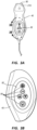
- FIG. 2 shows the general relation of these components to a patient 70 during a procedure to place a catheter 72 into the patient vasculature through a skin insertion site 73.
- FIG. 2 shows that the catheter 72 generally includes a proximal portion 74 that remains exterior to the patient and a distal potion 76 that resides within the patient vasculature after placement is complete.
- the system 10 is employed to ultimately position a distal tip 76A of the catheter 72 in a desired position within the patient vasculature.
- the desired position for the catheter distal tip 76A is proximate the patient's heart, such as in the lower one-third (1/3 rd ) portion of the Superior Vena Cava ("SVC").
- SVC Superior Vena Cava
- the system 10 can be employed to place the catheter distal tip in other locations.
- the catheter proximal portion 74 further includes a hub 74A that provides fluid communication between the one or more lumens of the catheter 72 and one or more extension legs 74B extending proximally from the hub.
- console 20 An example implementation of the console 20 is shown in FIG. 1 , though it is appreciated that the console can take one of a variety of forms.
- a digital controller/analog interface 24 is also included with the console 20 and is in communication with both the processor 22 and other system components to govern interfacing between the probe 40, sensor 50, and other system components.
- the system 10 further includes ports 52 for connection with the sensor 50 and optional components 54 including a printer, storage media, keyboard, etc.
- the ports in one embodiment are USB ports, though other port types or a combination of port types can be used for this and the other interfaces connections described herein.
- a power connection 56 is included with the console 20 to enable operable connection to an external power supply 58.
- An internal power supply 60 such as a battery, can also be employed, either with or exclusive of an external power supply.
- Power management circuitry 59 is included with the digital controller/analog interface 24 of the console to regulate power use and distribution.
- the display 30 in the present embodiment is integrated into the console 20 and is used to display information to the clinician during the catheter placement procedure.
- the display may be separate from the console.
- the content depicted by the display 30 changes according to which mode the catheter placement system is in: US, TLS, or in other embodiments, ECG tip confirmation.
- a console button interface 32 (see FIG. 1 ) and buttons included on the probe 40 can be used to immediately call up a desired mode to the display 30 by the clinician to assist in the placement procedure.
- information from multiple modes, such as TLS and ECG may be displayed simultaneously, such as in FIG. 4B .
- the single display 30 of the system console 20 can be employed for ultrasound guidance in accessing a patient's vasculature, TLS guidance during catheter advancement through the vasculature, and ECG-based confirmation of catheter distal tip placement with respect to a node of the patient's heart.
- the display 30 is an LCD, touchscreen display, or similar device.
- FIGS. 3A and 3B depict features of the probe 40 according to an embodiment.
- the probe 40 is employed in connection with the first modality disclosed herein, i.e., ultrasound ("US")-based visualization of a vessel, such as a vein, in preparation for insertion of the catheter 72 into the vasculature.
- US ultrasound
- Such visualization gives real time ultrasound guidance for introducing the catheter into the vasculature of the patient and assists in reducing complications typically associated with such introduction, including inadvertent arterial puncture, hematoma, pneumothorax, and the like.
- the handheld probe 40 includes a head 80 that houses a piezoelectric array for producing ultrasonic pulses and for receiving echoes thereof after reflection by the patient's body when the head is placed against the patient's skin proximate the prospective insertion site 73 ( FIG. 2 ).
- the probe 40 further includes a plurality of control buttons 84, which can be included on a button pad 82.
- the modality of the system 10 can be controlled by the control buttons 84, thus eliminating the need for the clinician to reach out of the sterile field, which is established about the patient insertion site prior to catheter placement, to change modes via use of the console button interface 32.
- control buttons 84 can also be located on a touchscreen display 30, as shown in FIG. 4B .
- a clinician employs the first (US) modality to determine a suitable insertion site and establish vascular access, such as with a needle or introducer, then with the catheter.
- the clinician can then seamlessly switch, via button pushes on the probe button pad 82, to the second (TLS) modality without having to reach out of the sterile field.
- the TLS mode can then be used to assist in advancement of the catheter 72 through the vasculature toward an intended destination.
- FIG. 1 shows that the probe 40 further includes button and memory controller 42 for governing button and probe operation.
- the button and memory controller 42 can include non-volatile memory, such as EEPROM, in an embodiment.
- the button and memory controller 42 is in operable communication with a probe interface 44 of the console 20, which includes a piezo input/output component 44A for interfacing with the probe piezoelectric array and a button and memory input/output component 44B for interfacing with the button and memory controller 42.
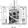
- FIG. 4A shows an example screenshot 88 as depicted on the display 30 while the system 10 is in its first ultrasound modality.
- An image 90 of a subcutaneous region of the patient 70 is shown, depicting a cross section of a vein 92.
- the image 90 is produced by operation of the piezoelectric array of the probe 40.
- a depth scale indicator 94 Also included on the display screenshot 88 is a depth scale indicator 94, providing information regarding the depth of the image 90 below the patient's skin, a lumen size scale 96 that provides information as to the size of the vein 92 relative to standard catheter lumen sizes, and other indicia 98 that provide information regarding status of the system 10 or possible actions to be taken, e.g., freeze frame, image templates, data save, image print, power status, image brightness, etc.
- the US mode shown in FIG. 4A can be simultaneously depicted on the display 30 with other modes, such as the TLS mode, if desired, e.g. FIG. 4B .
- aural information such as beeps, tones, etc., can also be employed by the system 10 to assist the clinician during catheter placement.
- the buttons included on the probe 40 and the console button interface 32, 84 can be configured in a variety of ways, including the use of user input controls in addition to buttons, such as slide switches, toggle switches, electronic or touch-sensitive pads, etc. Additionally, both US and TLS activities can occur simultaneously or exclusively during use of the system 10.
- the handheld ultrasound probe 40 is employed as part of the integrated catheter placement system 10 to enable US visualization of the peripheral vasculature of a patient in preparation for transcutaneous introduction of the catheter.
- the probe is also employed to control functionality of the TLS portion, or second modality, of the system 10 when navigating the catheter toward its desired destination within the vasculature as described below.
- the probe 40 is a dual-purpose device, enabling convenient control of both US and TLS functionality of the system 10 from the sterile field.
- the probe can also be employed to control some or all ECG-related functionality, or third modality, of the catheter placement system 10, as described herein.
- the catheter placement system 10 further includes the second modality described herein, i.e., the magnetically-based catheter TLS, or tip location system.
- the TLS enables the clinician to quickly locate and confirm the position and/or orientation of the catheter 72, such as a peripherally-inserted central catheter ("PICC"), central venous catheter (“CVC”), or other suitable catheter, during initial placement into and advancement through the vasculature of the patient 70.
- the TLS modality detects a magnetic field generated by a magnetic element-equipped tip location stylet, which is pre-loaded in one embodiment into a longitudinally defined lumen of the catheter 72, thus enabling the clinician to ascertain the general location and orientation of the catheter tip within the patient body.
- the magnetic assembly can be tracked using the teachings of one or more of the following U.S. patents: 5,775,322 ; 5,879,297 ; 6,129,668 ; 6,216,028 ; and 6,263,230 .
- the TLS also displays the direction in which the catheter tip is pointing, thus further assisting accurate catheter placement.
- the TLS further assists the clinician in determining when a malposition of the catheter tip has occurred, such as in the case where the tip has deviated from a desired venous path into another vein.
- the system 10 can include additional functionality wherein determination of the proximity of the catheter distal tip 76A relative to a sino-atrial ("SA") or other electrical impulse-emitting node of the heart of the patient 70 can be determined, thus providing enhanced ability to accurately place the catheter distal tip in a desired location proximate the node.
- SA sino-atrial
- ECG ECG-based tip confirmation
- this third modality of the system 10 enables detection of ECG signals from the SA node in order to place the catheter distal tip in a desired location within the patient vasculature.
- the US, TLS, and ECG modalities are seamlessly combined in the present system 10 and can be employed in concert or individually to assist in catheter placement. Further details regarding the catheter placement system described herein can be found in U.S. Patent No. 8,388,541 , titled "Integrated System for Intravascular Placement of a Catheter,”.
- the ultrasound (“US") portion of the system 10 further includes additional imaging functionality to enable an enhanced subcutaneous view of the patient body to be achieved.
- the additional imaging functionality is provided by an emitter 214, detector 216 and console 20.
- the emitter 214 is included with a needle 210 that is employed to gain access to a vein or other subcutaneous vessel or body portion. As shown in FIGS. 5A-5C as the needle 210/emitter 214 penetrates the skin surface and vasculature 222, different tissue types are illuminated as they respond differently to the light provided by the emitter 214.
- the emitter 214 is included at a distal end of a stylet 212 that is removably received within the lumen defined by the needle 210.
- the emitter 214 is positioned so as to be disposed at the distal end of the needle 210, and is configured to emit a light signal of a predetermined wavelength or wavelength range.
- the emitter 214 can be included as a component on the needle 210 itself, or on another component to be inserted into the patient such as a catheter, guidewire, or the like. It will be appreciated that one or more additional devices such as catheters, guidewires, introducers, and the like can also be disposed within the lumen of the needle 210.
- the stylet 212 includes a fiber optic cable that extends the length of the stylet 212 to the emitter 214 disposed at a distal end thereof.
- a light source 230 can be disposed proximally of the emitter 214 and generate a source of light including a given wavelength or range of wavelengths. The light can then be communicated to the emitter 214 by the fiber optic cable.
- the light source 230 can be a Light Emitting Diode (LED), tungsten bulb, fluorescent bulb, or similar suitable light source capable of emitting a desired wavelength or range of wavelengths.
- LED Light Emitting Diode
- the light source 230 is part of the emitter 214 and are both disposed at a distal end of the stylet 212 as a single unit.
- a cable can extend proximally from the emitter 214 to a power source.
- the power source is a battery, mains power, or similar suitable power source, or combinations thereof.
- a light detector 216 can be included with the probe 40 and positioned proximate the head 80 of the probe. It will be appreciated that the light detector 216 can also be included with another component or as a standalone configuration device. The detector 216 is configured to detect light emitted by the emitter 214 after the needle 210 has been inserted subcutaneously into the patient 70. In an embodiment, the system 10 includes an array of detectors 216, one or more of which can be included with the probe 40.
- the emitter 214 is configured to emit light within the infrared wavelength range. In an embodiment, the emitter 214 is configured to emit light within the near-infrared range including wavelengths from about 780 nm to about 3000 nm, which is an optical window for biological tissue. Light in the foregoing optical window, is capable of penetrating biological tissue more deeply than light outside the foregoing range of wavelengths. The infrared light penetrating and reflecting off of the tissue provide differing spectra of absorption coefficients depending on the different tissue components included in the tissue. Exemplary tissue components include oxyhemoglobin, deoxyhemoglobin, water, melanin, fat, etc., each of which show different profiles of absorption peaks across the infrared range.
- FIGS. 8A-8B Exemplary absorption spectra are shown in FIGS. 8A-8B , where FIG. 8A shows the absorption spectra for both Oxyhemoglobin and Deoxyhemoglobin and FIG. 8B shows an absorption spectra for water. Accordingly, different tissue types, which include differing proportions of these tissue components, provide signature absorption spectra that can be detected and interpreted.
- the subcutaneous tissue 220, between the skin surface and the vessel will have different proportion of blood, water, melanin, fat, etc. than that of the vessel wall, vessel 222, and deeper tissues 224 below the vessel 222.
- the light from the emitter 214 is reflected differently from these different tissue types, which can be detected and interpreted by the detector 216.
- the vessel being accessed can be identified as arterial or venous depending on the proportion of oxyhemoglobin and deoxyhemoglobin detected.
- the boundary layer between two different tissue types provides a difference in impedance which can reflect a portion of the light back into the tissue.
- the emitter 214 disposed within different tissue structures 220, 222, 224 illuminates the structures and highlights the boundaries between the structures. Detecting and interpreting the wavelength profiles of the reflected light can provide information regarding the location of the emitter. This light-based information can be superimposed on an ultrasound image of the vessel to facilitate first-stick access of patient vasculature.
- the processor 22 of the system 10 can process the light-based information, sensed by the detector 216, and combine them with the ultrasound imaging data acquired by the ultrasound probe 40 to produce an enhanced image. Further examples of enhanced images are shown in FIGS. 5A-7C , together with the needle 210, stylet 212, and the emitter 214.
- FIGS. 5A-5C A show a front end view of subcutaneous tissue and a vessel 222 to be accessed. As shown in FIG. 5A , as the needle 210 penetrates the skin surface of the patient, light from the emitter 214 penetrates and illuminates subcutaneous body tissue 220 surrounding a target vessel 222. As shown in FIG.
- FIGS. 5A-5C Visualization of these different needle distal tip positions of FIGS. 5A-5C can be superimposed atop the traditional ultrasound image, for example, as shown in FIG. 4C .
- This provides an enhanced ultrasound/infrared image of the vessel and the position of the distal tip of the needle 210 relative thereto, depicted on the display 30 (or other suitable output device). In turn, this will assist the clinician in determining when the distal tip of the needle 210 is desirably disposed within the lumen of the vessel 222 or other body portion.
- the system 10 can provide various differently angled views of the enhanced image, including a transverse, front-end view ( FIGS. 5A-5C ), a longitudinal, side-profile view ( FIGS. 6A-6C ), a top-down, plan-view, (( FIGS. 7A-7C ), a three-dimensionally rendered image, or combinations thereof.
- FIGS. 6A-6C show an enhanced side-view US-images during the insertion of the needle 210, both prior to insertion of the needle 210 into the vessel 222 ( FIG. 6A ), accessing the vessel 222 ( FIG. 6B ), and where the needle 210 has breached the far side of the vessel 222 ( FIG. 6C).
- FIG. 6A shows an enhanced side-view image where the tip of the needle 210, including the emitter 214, is at or within the subcutaneous tissue 220 that is above the vessel 222. These tissues surrounding the vessel 220 are illuminated while the vessel 222 itself remains unilluminated due to the attenuation of the light at the wall of the vessel.
- FIG 6B shows an enhanced side-view image where the tip of the needle 210, and the emitter 214, has passed through the vessel wall and entered the vessel 222.
- the vessel 220 itself is now illuminated while the tissues surrounding the vessel 222 remain unilluminated.
- FIG. 6C shows an enhanced side-view image where the tip of the needle 210, including the emitter 214, has passed through the vessel wall on a far side, breaching the vessel and entering the tissues below the vessel 222.
- the tissues below the vessel 222 are now illuminated while the vessel 222 itself is now unilluminated.
- FIGS. 7A-7C show a plan-view of enhanced US-images during the insertion of the needle 210, both prior to insertion of the vessel 222 ( FIG. 7A ), accessing the vessel 222 ( FIG. 7B ), and where the needle 210 has breached the far side of the vessel 222 ( FIG. 7C).
- FIG. 7A shows an enhanced image where the tip of the needle 210 including the emitter 214 is at or within the subcutaneous tissue that is above the vessel 222.
- the tissues surrounding the vessel 220 are illuminated while the vessel 222 itself remains unilluminated.
- this highlights the boundaries of the vessel 222 which helps guide the position of the needle to a mid-point of the vessel 222.
- FIG. 7B shows an enhanced side-view image where the tip of the needle 210, and the emitter 214, has passed through the vessel wall and entered the vessel 222.
- the vessel 220 itself is now illuminated while the tissues surrounding the vessel 222 remain unilluminated.
- FIG. 7C shows an enhanced side-view image where the tip of the needle 210, including the emitter 214, has passed through the vessel wall on a far side, breaching the vessel and entering the tissues below the vessel 222.
- the tissues below the vessel 222 are now illuminated while the vessel 222 itself is now unilluminated.
- the detector 216 can determine differences between arterial and venous vasculature based on the profile of absorbance spectra of reflected light.
- the wavelengths provided by the emitter 214, and the wavelengths received by the detector 216 can be compared and identified as either "red-shifted” or "blue-shifted” to determine if the vessel 222 being accessed is arterial or venous, respectively.
- the system 10 can then indicate these differences either on the display 30 or by various visual, auditory, or tactile alerts as described herein.
- the light detector 216 and console 20 can detect and reproduce the illuminated portions on the display 30 and superimpose these images onto the US image of the same area.
- the detector 216 can detect more subtle differences in reflected or absorbed light that would otherwise be indeterminable by the human eye. Accordingly, the detector 216 can detect and interpret the light-based information, and reproduce these data as enhanced images on the display 30.
- the system 10 can provide various visual, auditory, and/or tactile alerts, as the position of the needle tip/emitter 214 moves, relative to the vessel 222.
- the display 30 can provide an image of the needle relative to the vessel. Once the needle tip has entered the vessel 222, the display can provide an alert, such as green tick. If the needle 210 is advanced too far and breaches the far side of the vessel, entering the tissues 224, an auditory alert, or a tactile vibration can indicate to the user that the needle 210 has been advanced too far. Auditory and tactile alerts advantageously notify the user without the user needing to observe the display 30.
Landscapes
- Health & Medical Sciences (AREA)
- Life Sciences & Earth Sciences (AREA)
- Surgery (AREA)
- Physics & Mathematics (AREA)
- Engineering & Computer Science (AREA)
- Molecular Biology (AREA)
- Animal Behavior & Ethology (AREA)
- Biomedical Technology (AREA)
- Heart & Thoracic Surgery (AREA)
- Medical Informatics (AREA)
- Biophysics (AREA)
- Nuclear Medicine, Radiotherapy & Molecular Imaging (AREA)
- Pathology (AREA)
- General Health & Medical Sciences (AREA)
- Public Health (AREA)
- Veterinary Medicine (AREA)
- Radiology & Medical Imaging (AREA)
- Optics & Photonics (AREA)
- Spectroscopy & Molecular Physics (AREA)
- Signal Processing (AREA)
- Ultra Sonic Daignosis Equipment (AREA)
Claims (10)
- Système d'imagerie pour faciliter l'accès vasculaire par première piqûre d'un patient avec une aiguille (210), comprenant :une sonde ultrasonore (40) pour produire et recevoir des signaux ultrasonores ;un émetteur (214) configuré pour émettre une lumière infrarouge à partir d'une pointe distale de l'aiguille (210) ;un détecteur (216) configuré pour détecter la lumière infrarouge émise par l'émetteur (214) ; etun écran (30) configuré pour fournir une image ultrasonore améliorée incluant des informations ultrasonores provenant de la sonde ultrasonore (40) et des informations basées sur la lumière provenant du détecteur (216).
- Système selon la revendication 1, dans lequel l'émetteur (214) est configuré pour émettre de la lumière dans une plage de longueurs d'onde entre 780 nm et 3000 nm.
- Système selon la revendication 1, dans lequel l'émetteur (214) inclut une source de lumière (230) configurée pour produire la lumière infrarouge.
- Système selon la revendication 1, incluant en outre une source de lumière (230) configurée pour produire la lumière infrarouge et positionnée à proximité de l'émetteur, et un câble à fibre optique s'étendant de la source de lumière (230) à l'émetteur (214), configuré pour communiquer la lumière infrarouge entre la source de lumière (230) et l'émetteur (214).
- Système selon la revendication 1, dans lequel le détecteur (216) est inclus avec une extrémité distale de la sonde (40).
- Système selon la revendication 1, dans lequel les informations basées sur la lumière provenant du détecteur (216) incluent une image d'une partie éclairée du patient.
- Système selon la revendication 1, dans lequel les informations basées sur la lumière provenant du détecteur (216) incluent la détection et l'interprétation des spectres d'absorption de la lumière réfléchie pour déterminer un type de structure tissulaire que l'émetteur (214) éclaire.
- Système selon la revendication 1, dans lequel le détecteur détermine qu'une lumière réfléchie de l'émetteur (214) est décalée vers le rouge et indique qu'un vaisseau auquel on accède est artériel.
- Système selon la revendication 1, dans lequel le détecteur détermine qu'une lumière réfléchie de l'émetteur (214) est décalée vers le bleu et indique qu'un vaisseau auquel on accède est veineux.
- Système selon la revendication 1, dans lequel l'émetteur (214) est inclus avec une extrémité distale d'un stylet (212), disposé à l'intérieur d'une lumière de l'aiguille (210).
Applications Claiming Priority (2)
| Application Number | Priority Date | Filing Date | Title |
|---|---|---|---|
| US201862721358P | 2018-08-22 | 2018-08-22 | |
| PCT/US2019/047756 WO2020041622A1 (fr) | 2018-08-22 | 2019-08-22 | Systèmes et procédés de visualisation par ultrasons améliorés par infrarouge |
Publications (4)
| Publication Number | Publication Date |
|---|---|
| EP3840636A1 EP3840636A1 (fr) | 2021-06-30 |
| EP3840636A4 EP3840636A4 (fr) | 2022-05-11 |
| EP3840636C0 EP3840636C0 (fr) | 2024-10-23 |
| EP3840636B1 true EP3840636B1 (fr) | 2024-10-23 |
Family
ID=69583271
Family Applications (1)
| Application Number | Title | Priority Date | Filing Date |
|---|---|---|---|
| EP19852441.5A Active EP3840636B1 (fr) | 2018-08-22 | 2019-08-22 | Systèmes de visualisation par ultrasons améliorés par infrarouge |
Country Status (4)
| Country | Link |
|---|---|
| US (1) | US12569221B2 (fr) |
| EP (1) | EP3840636B1 (fr) |
| CN (1) | CN112584756B (fr) |
| WO (1) | WO2020041622A1 (fr) |
Families Citing this family (3)
| Publication number | Priority date | Publication date | Assignee | Title |
|---|---|---|---|---|
| US12011339B2 (en) * | 2020-08-25 | 2024-06-18 | Guy Francis Merz | Ears disimpactor |
| US20230420105A1 (en) | 2022-06-24 | 2023-12-28 | Bard Access Systems, Inc. | Systems and Methods for Automatic Determination of a Medical Device for Vascular Access |
| CN117426807B (zh) * | 2023-12-18 | 2024-03-12 | 中国医学科学院北京协和医院 | 一种用于腹腔镜手术术中使用的血管红外定位系统 |
Citations (1)
| Publication number | Priority date | Publication date | Assignee | Title |
|---|---|---|---|---|
| CN205031338U (zh) * | 2015-07-16 | 2016-02-17 | 执鼎医疗科技江苏有限公司 | 一种红外引导超声定位的静脉穿刺系统 |
Family Cites Families (112)
| Publication number | Priority date | Publication date | Assignee | Title |
|---|---|---|---|---|
| CN1049287A (zh) | 1989-05-24 | 1991-02-20 | 住友电气工业株式会社 | 治疗导管 |
| EP0573535B1 (fr) | 1991-02-26 | 2000-12-27 | Massachusetts Institute Of Technology | Systemes et procedes de spectroscopie moleculaire, permettant d'etablir le diagnostic des tissus |
| US5211165A (en) | 1991-09-03 | 1993-05-18 | General Electric Company | Tracking system to follow the position and orientation of a device with radiofrequency field gradients |
| US5423321A (en) | 1993-02-11 | 1995-06-13 | Fontenot; Mark G. | Detection of anatomic passages using infrared emitting catheter |
| AU6666894A (en) | 1993-04-22 | 1994-11-08 | Pixsys, Inc. | System for locating relative positions of objects |
| US6597941B2 (en) | 1994-09-15 | 2003-07-22 | Stryker Corporation | Transillumination of body members for protection during body invasive procedures |
| US5517997A (en) | 1994-09-15 | 1996-05-21 | Gabriel Medical, Inc. | Transillumination of body members for protection during body invasive procedures |
| US5879306A (en) | 1996-06-13 | 1999-03-09 | Stryker Corporation | Infrared system for visualizing body members |
| US5775322A (en) | 1996-06-27 | 1998-07-07 | Lucent Medical Systems, Inc. | Tracheal tube and methods related thereto |
| US5904147A (en) | 1996-08-16 | 1999-05-18 | University Of Massachusetts | Intravascular catheter and method of controlling hemorrhage during minimally invasive surgery |
| US7603166B2 (en) | 1996-09-20 | 2009-10-13 | Board Of Regents University Of Texas System | Method and apparatus for detection of vulnerable atherosclerotic plaque |
| US6119031A (en) | 1996-11-21 | 2000-09-12 | Boston Scientific Corporation | Miniature spectrometer |
| US6129668A (en) | 1997-05-08 | 2000-10-10 | Lucent Medical Systems, Inc. | System and method to determine the location and orientation of an indwelling medical device |
| US6263230B1 (en) | 1997-05-08 | 2001-07-17 | Lucent Medical Systems, Inc. | System and method to determine the location and orientation of an indwelling medical device |
| US5879297A (en) | 1997-05-08 | 1999-03-09 | Lucent Medical Systems, Inc. | System and method to determine the location and orientation of an indwelling medical device |
| US6081741A (en) | 1998-06-05 | 2000-06-27 | Vector Medical, Inc. | Infrared surgical site locating device and method |
| CA2334978A1 (fr) | 1998-06-09 | 1999-12-16 | Steve Baker | Catheter cardio-vasculaire et procede de mise en place de catheter a l'aide de la transillumination de tissus |
| AU4644799A (en) | 1998-08-02 | 2000-03-14 | Super Dimension Ltd. | Intrabody navigation system for medical applications |
| AU6417599A (en) | 1998-10-08 | 2000-04-26 | University Of Kentucky Research Foundation, The | Methods and apparatus for (in vivo) identification and characterization of vulnerable atherosclerotic plaques |
| US6178346B1 (en) | 1998-10-23 | 2001-01-23 | David C. Amundson | Infrared endoscopic imaging in a liquid with suspended particles: method and apparatus |
| US6208887B1 (en) | 1999-06-24 | 2001-03-27 | Richard H. Clarke | Catheter-delivered low resolution Raman scattering analyzing system for detecting lesions |
| US7935108B2 (en) | 1999-07-14 | 2011-05-03 | Cardiofocus, Inc. | Deflectable sheath catheters |
| US7366562B2 (en) | 2003-10-17 | 2008-04-29 | Medtronic Navigation, Inc. | Method and apparatus for surgical navigation |
| US6685666B1 (en) | 1999-11-12 | 2004-02-03 | Mark G. Fontenot | Catheters for breast surgery |
| US6692430B2 (en) | 2000-04-10 | 2004-02-17 | C2Cure Inc. | Intra vascular imaging apparatus |
| US6650923B1 (en) | 2000-04-13 | 2003-11-18 | Ev3 Sunnyvale, Inc. | Method for accessing the left atrium of the heart by locating the fossa ovalis |
| DE60141090D1 (de) | 2000-10-30 | 2010-03-04 | Gen Hospital Corp | Optische systeme zur gewebeanalyse |
| US6820614B2 (en) * | 2000-12-02 | 2004-11-23 | The Bonutti 2003 Trust -A | Tracheal intubination |
| US20020115922A1 (en) | 2001-02-12 | 2002-08-22 | Milton Waner | Infrared assisted monitoring of a catheter |
| EP2333521B1 (fr) | 2001-04-30 | 2019-12-04 | The General Hospital Corporation | Procédé et appareil permettant d'améliorer la clarté et la sensibilité de l'image en tomographie à cohérence optique au moyen d'une interaction permettant de contrôler les propriétés focales et la synchronisation de cohérence |
| US7532920B1 (en) | 2001-05-31 | 2009-05-12 | Advanced Cardiovascular Systems, Inc. | Guidewire with optical fiber |
| US6701181B2 (en) | 2001-05-31 | 2004-03-02 | Infraredx, Inc. | Multi-path optical catheter |
| WO2002103409A2 (fr) | 2001-06-19 | 2002-12-27 | The Trustees Of The University Of Pennsylvania | Systeme de guidage optique pour placement de catheter invasif |
| US7992573B2 (en) * | 2001-06-19 | 2011-08-09 | The Trustees Of The University Of Pennsylvania | Optically guided system for precise placement of a medical catheter in a patient |
| US6895267B2 (en) | 2001-10-24 | 2005-05-17 | Scimed Life Systems, Inc. | Systems and methods for guiding and locating functional elements on medical devices positioned in a body |
| US20030092995A1 (en) | 2001-11-13 | 2003-05-15 | Medtronic, Inc. | System and method of positioning implantable medical devices |
| US6711426B2 (en) | 2002-04-09 | 2004-03-23 | Spectros Corporation | Spectroscopy illuminator with improved delivery efficiency for high optical density and reduced thermal load |
| US6690958B1 (en) * | 2002-05-07 | 2004-02-10 | Nostix Llc | Ultrasound-guided near infrared spectrophotometer |
| EP1526888A2 (fr) | 2002-08-05 | 2005-05-04 | Miravant Medical Technologies | Catheter d'apport de lumiere |
| EP1551299A4 (fr) | 2002-08-05 | 2010-01-20 | Infraredx Inc | Analyse spectroscopique par proche infrarouge des parois de vaisseaux sanguins |
| US6892090B2 (en) | 2002-08-19 | 2005-05-10 | Surgical Navigation Technologies, Inc. | Method and apparatus for virtual endoscopy |
| US20040215072A1 (en) * | 2003-01-24 | 2004-10-28 | Quing Zhu | Method of medical imaging using combined near infrared diffusive light and ultrasound |
| CN100382750C (zh) | 2003-03-07 | 2008-04-23 | 皇家飞利浦电子股份有限公司 | 体内定位器械的装置和方法 |
| US7132645B2 (en) | 2003-03-07 | 2006-11-07 | Infraredx, Inc. | System and method for assessing catheter connection using return loss |
| DE10323217A1 (de) | 2003-05-22 | 2004-12-16 | Siemens Ag | Optisches Kohärenztomographiesystem zur Untersuchung des menschlichen oder tierischen Gewebes oder von Organen |
| US7840253B2 (en) | 2003-10-17 | 2010-11-23 | Medtronic Navigation, Inc. | Method and apparatus for surgical navigation |
| JP2007508913A (ja) * | 2003-10-21 | 2007-04-12 | ザ ボード オブ トラスティーズ オブ ザ リーランド スタンフォード ジュニア ユニヴァーシティ | 術中ターゲティングのシステムおよび方法 |
| US8571640B2 (en) | 2003-12-11 | 2013-10-29 | The Regents Of The University Of California | Catheter based mid-infrared reflectance and reflectance generated absorption spectroscopy |
| DE10358735B4 (de) | 2003-12-15 | 2011-04-21 | Siemens Ag | Kathetereinrichtung umfassend einen Katheter, insbesondere einen intravaskulären Katheter |
| US7587236B2 (en) | 2004-01-08 | 2009-09-08 | Lawrence Livermore National Security, Llc | Optical spectroscopy for the detection of ischemic tissue injury |
| DE102005012699A1 (de) | 2005-03-18 | 2006-09-28 | Siemens Ag | Verfahren zur medizinischen Bildgebung sowie medizinisches bildgebendes System |
| WO2006116701A2 (fr) | 2005-04-28 | 2006-11-02 | Research Foundation Of The City University Of New York | Systemes et procedes d'imagerie pour ameliorer l'imagerie de retrodiffusion a l'aide d'une memoire a polymerisation circulaire |
| US8597193B2 (en) * | 2005-05-06 | 2013-12-03 | Vasonova, Inc. | Apparatus and method for endovascular device guiding and positioning using physiological parameters |
| US20070073160A1 (en) | 2005-09-13 | 2007-03-29 | Children's Medical Center Corporation | Light-guided transluminal catheter |
| US8954134B2 (en) | 2005-09-13 | 2015-02-10 | Children's Medical Center Corporation | Light-guided transluminal catheter |
| US8187189B2 (en) | 2006-04-28 | 2012-05-29 | The Invention Science Fund I, Llc | Imaging via blood vessels |
| US9596994B2 (en) * | 2006-06-02 | 2017-03-21 | J. William J. Futrell | System and methods for illuminating materials |
| WO2008005554A2 (fr) * | 2006-07-06 | 2008-01-10 | University Of Connecticut | Procédé et appareil d'imagerie médicale utilisant la tomographie optique proche infrarouge et la tomographie de fluorescence associée à des ultrasons |
| US10772600B2 (en) * | 2015-09-25 | 2020-09-15 | Perceptive Navigation Llc | Image guided catheters and methods of use |
| US7931647B2 (en) * | 2006-10-20 | 2011-04-26 | Asthmatx, Inc. | Method of delivering energy to a lung airway using markers |
| US7729735B1 (en) | 2006-11-30 | 2010-06-01 | Dartmouth-Hitchcock Clinic | System and method for venous oximetry using a catheter |
| US8073517B1 (en) | 2006-11-30 | 2011-12-06 | Dartmouth-Hitchcock Clinic | System and method for measuring blood constituents using a catheter |
| TW200824643A (en) * | 2006-12-13 | 2008-06-16 | Chieh-Hsiao Chen | Guiding stylet apparatus |
| US20080172119A1 (en) | 2007-01-12 | 2008-07-17 | Medtronic Vascular, Inc. | Prosthesis Deployment Apparatus and Methods |
| US8460195B2 (en) * | 2007-01-19 | 2013-06-11 | Sunnybrook Health Sciences Centre | Scanning mechanisms for imaging probe |
| CN101925333B (zh) | 2007-11-26 | 2014-02-12 | C·R·巴德股份有限公司 | 用于脉管系统内的导管放置的集成系统 |
| US9649048B2 (en) | 2007-11-26 | 2017-05-16 | C. R. Bard, Inc. | Systems and methods for breaching a sterile field for intravascular placement of a catheter |
| US10751509B2 (en) | 2007-11-26 | 2020-08-25 | C. R. Bard, Inc. | Iconic representations for guidance of an indwelling medical device |
| US10524691B2 (en) | 2007-11-26 | 2020-01-07 | C. R. Bard, Inc. | Needle assembly including an aligned magnetic element |
| US9521961B2 (en) * | 2007-11-26 | 2016-12-20 | C. R. Bard, Inc. | Systems and methods for guiding a medical instrument |
| US10449330B2 (en) | 2007-11-26 | 2019-10-22 | C. R. Bard, Inc. | Magnetic element-equipped needle assemblies |
| US9211160B2 (en) | 2008-01-16 | 2015-12-15 | Luiz Geraldo Pivotto | Remotely controlled catheter insertion system with automatic control system |
| WO2010019515A2 (fr) * | 2008-08-10 | 2010-02-18 | Board Of Regents, The University Of Texas System | Appareil d'imagerie hyperspectrale à traitement de lumière numérique |
| US20100069760A1 (en) * | 2008-09-17 | 2010-03-18 | Cornova, Inc. | Methods and apparatus for analyzing and locally treating a body lumen |
| US20110245662A1 (en) | 2010-04-06 | 2011-10-06 | Eggers Philip E | Hemodynamic Detection of Circulatory Anomalies |
| RU2544465C2 (ru) * | 2009-06-10 | 2015-03-20 | Конинклейке Филипс Электроникс Н.В. | Алгоритм для консоли фотонной иглы |
| WO2010146588A2 (fr) | 2009-06-16 | 2010-12-23 | Technion- Research And Development Foundation Ltd. | Système miniature permettant de diagnostiquer une maladie |
| US20120209359A1 (en) * | 2009-08-14 | 2012-08-16 | Light Sciences Oncology Inc. | Low-profile intraluminal light delivery system and methods of using the same |
| CN102665541B (zh) | 2009-09-29 | 2016-01-13 | C·R·巴德股份有限公司 | 与用于导管的血管内放置的设备一起使用的探针 |
| CN102770071B (zh) * | 2009-12-15 | 2015-03-25 | 爱默蕾大学 | 用于在诊断或治疗程序中提供实时解剖学指导的系统和方法 |
| US20110166442A1 (en) * | 2010-01-07 | 2011-07-07 | Artann Laboratories, Inc. | System for optically detecting position of an indwelling catheter |
| US8369932B2 (en) | 2010-01-29 | 2013-02-05 | Medtronic Ablation Frontiers Llc | Optical methods of identifying the location of a medical device within a patient's body in order to locate the fossa ovalis for trans-septal procedures |
| US20110245659A1 (en) * | 2010-04-01 | 2011-10-06 | Sonosite, Inc. | Systems and methods to assist with internal positioning of instruments |
| US8798721B2 (en) | 2010-05-26 | 2014-08-05 | Dib Ultrasound Catheter, Llc | System and method for visualizing catheter placement in a vasculature |
| EP2912999B1 (fr) * | 2010-05-28 | 2022-06-29 | C. R. Bard, Inc. | Appareil destiné à être utilisé avec un système de guidage d'insertion d'aiguille |
| CA3054544C (fr) * | 2010-05-28 | 2022-01-04 | C.R. Bard, Inc. | Appareil convenant a une utilisation avec un systeme de guidage d'insertion d'aiguille |
| EP2624754B1 (fr) | 2010-10-08 | 2018-08-22 | Edwards Lifesciences Corporation | Système, procédé et produit programme informatique pour mesure optique de paramètres sanguins |
| US9345389B2 (en) * | 2010-11-12 | 2016-05-24 | Emory University | Additional systems and methods for providing real-time anatomical guidance in a diagnostic or therapeutic procedure |
| AU2012278809B2 (en) | 2011-07-06 | 2016-09-29 | C.R. Bard, Inc. | Needle length determination and calibration for insertion guidance system |
| CA2851659A1 (fr) * | 2011-10-09 | 2013-04-18 | Clear Guide Medical, Llc | Guidage d'images in situ interventionnelles par fusion d'une video ultrasonore |
| US20130211246A1 (en) | 2011-12-27 | 2013-08-15 | Vinod PARASHER | METHODS AND DEVICES FOR GASTROINTESTINAL SURGICAL PROCEDURES USING NEAR INFRARED (nIR) IMAGING TECHNIQUES |
| CN104023635A (zh) * | 2011-12-30 | 2014-09-03 | 皇家飞利浦有限公司 | 用于在us成像中使用pa效应进行针导航的系统和方法 |
| US10034647B2 (en) | 2012-03-16 | 2018-07-31 | Xidian University | System and method for endoscopic X-ray luminescence computed tomographic imaging |
| US20140121468A1 (en) | 2012-10-26 | 2014-05-01 | Halma Holdings, Inc. | Spectroscopic illumination device using white light leds |
| US20140221829A1 (en) | 2013-02-01 | 2014-08-07 | The Texas A&M University System | Localized fluorescence excitation in whole body optical imaging |
| US20160008057A1 (en) * | 2013-02-27 | 2016-01-14 | Empire Technology Development Llc | Diagnostic needle probe |
| GB201307551D0 (en) * | 2013-04-26 | 2013-06-12 | Ucl Business Plc | A method and apparatus for determining the location of a medical instrument with respect to ultrasound imaging and a medical instrument |
| EP2829222B1 (fr) | 2013-07-24 | 2020-05-27 | Cook Medical Technologies LLC | Dispositif de localisation |
| FR3011170B1 (fr) * | 2013-09-30 | 2017-03-31 | Apd Advanced Perfusion Diagnostics | Dispositif et procede de mesure non invasive pour l'estimation de parametres metaboliques locaux |
| US9907471B2 (en) | 2013-10-08 | 2018-03-06 | The Board Of Trustees Of The Leland Stanford Junior University | Visualization of heart wall tissue |
| WO2015056257A1 (fr) * | 2013-10-14 | 2015-04-23 | Avraham Aharoni | Dispositif et système pour représenter des veines |
| US20150257735A1 (en) * | 2013-10-24 | 2015-09-17 | Evena Medical, Inc. | Systems and methods for displaying medical images |
| WO2015074045A2 (fr) | 2013-11-18 | 2015-05-21 | Jeremy Stigall | Cathéter d'administration thérapeutique avec imagerie et caractérisation tissulaire |
| JP6487455B2 (ja) | 2014-01-29 | 2019-03-20 | ベクトン・ディキンソン・アンド・カンパニーBecton, Dickinson And Company | 侵襲性デバイスの挿入中に可視化を向上させるための装着可能な電子デバイス |
| US20150327836A1 (en) * | 2014-05-16 | 2015-11-19 | University Of Virginia Patent Foundation | Endovascular occlusion device and method of use |
| JP6486733B2 (ja) * | 2015-03-17 | 2019-03-20 | 株式会社東芝 | 超音波診断装置及び生体検査装置 |
| JP6408136B2 (ja) * | 2015-03-30 | 2018-10-17 | 富士フイルム株式会社 | 生検針および光音響計測装置 |
| EP3307353A4 (fr) * | 2015-06-15 | 2019-03-13 | The University Of Sydney | Système et procédé d'insertion |
| US11033209B2 (en) * | 2015-11-30 | 2021-06-15 | Technion Research & Development Foundation Limited | Hemoglobin measurement from a single vessel |
| US10973586B2 (en) * | 2016-01-19 | 2021-04-13 | Verum Tcs, Llc | Systems and methods of determining one or more properties of a catheter and a distal tip thereof |
| US10788791B2 (en) * | 2016-02-22 | 2020-09-29 | Real View Imaging Ltd. | Method and system for displaying holographic images within a real object |
| US11439742B2 (en) * | 2017-02-08 | 2022-09-13 | Veran Medical Technologies, Inc. | Localization needle |
-
2019
- 2019-08-22 EP EP19852441.5A patent/EP3840636B1/fr active Active
- 2019-08-22 CN CN201980055148.6A patent/CN112584756B/zh active Active
- 2019-08-22 WO PCT/US2019/047756 patent/WO2020041622A1/fr not_active Ceased
- 2019-08-22 US US16/548,607 patent/US12569221B2/en active Active
Patent Citations (1)
| Publication number | Priority date | Publication date | Assignee | Title |
|---|---|---|---|---|
| CN205031338U (zh) * | 2015-07-16 | 2016-02-17 | 执鼎医疗科技江苏有限公司 | 一种红外引导超声定位的静脉穿刺系统 |
Also Published As
| Publication number | Publication date |
|---|---|
| US20200060643A1 (en) | 2020-02-27 |
| CN112584756B (zh) | 2024-09-13 |
| EP3840636A4 (fr) | 2022-05-11 |
| EP3840636C0 (fr) | 2024-10-23 |
| CN112584756A (zh) | 2021-03-30 |
| WO2020041622A1 (fr) | 2020-02-27 |
| US12569221B2 (en) | 2026-03-10 |
| EP3840636A1 (fr) | 2021-06-30 |
Similar Documents
| Publication | Publication Date | Title |
|---|---|---|
| US12343091B2 (en) | Apparatus and methods relating to intravascular positioning of distal end of catheter | |
| US20250060266A1 (en) | Optical Fiber-Based Medical Device Tracking and Monitoring System | |
| US11832894B2 (en) | Adjustable length medical instrument assembly with localization elements for tracking medical instrument extension | |
| US11707205B2 (en) | Integrated system for intravascular placement of a catheter | |
| JP2016104192A (ja) | 針挿入誘導システムとともに使用するための装置 | |
| EP3840636B1 (fr) | Systèmes de visualisation par ultrasons améliorés par infrarouge | |
| US11759268B2 (en) | Apparatus and methods relating to intravascular positioning of distal end of catheter | |
| AU2013201648B2 (en) | Integrated system for intravascular placement of a catheter | |
| KR20230099249A (ko) | 카테터를 조절하는 네비게이션 장치 및 이를 포함하는 네비게이션 시스템 | |
| WO2026043747A1 (fr) | Système et procédés de navigation de dispositif médical photoacoustique |
Legal Events
| Date | Code | Title | Description |
|---|---|---|---|
| STAA | Information on the status of an ep patent application or granted ep patent |
Free format text: STATUS: THE INTERNATIONAL PUBLICATION HAS BEEN MADE |
|
| PUAI | Public reference made under article 153(3) epc to a published international application that has entered the european phase |
Free format text: ORIGINAL CODE: 0009012 |
|
| STAA | Information on the status of an ep patent application or granted ep patent |
Free format text: STATUS: REQUEST FOR EXAMINATION WAS MADE |
|
| 17P | Request for examination filed |
Effective date: 20210318 |
|
| AK | Designated contracting states |
Kind code of ref document: A1 Designated state(s): AL AT BE BG CH CY CZ DE DK EE ES FI FR GB GR HR HU IE IS IT LI LT LU LV MC MK MT NL NO PL PT RO RS SE SI SK SM TR |
|
| DAV | Request for validation of the european patent (deleted) | ||
| DAX | Request for extension of the european patent (deleted) | ||
| A4 | Supplementary search report drawn up and despatched |
Effective date: 20220413 |
|
| RIC1 | Information provided on ipc code assigned before grant |
Ipc: A61B 1/07 20060101ALN20220407BHEP Ipc: A61B 1/00 20060101ALI20220407BHEP Ipc: A61B 1/04 20060101ALI20220407BHEP Ipc: A61M 5/00 20060101ALI20220407BHEP Ipc: A61B 17/00 20060101ALI20220407BHEP Ipc: A61B 8/12 20060101ALI20220407BHEP Ipc: A61B 8/08 20060101ALI20220407BHEP Ipc: A61B 8/00 20060101ALI20220407BHEP Ipc: A61B 6/00 20060101ALI20220407BHEP Ipc: A61B 5/00 20060101AFI20220407BHEP |
|
| GRAP | Despatch of communication of intention to grant a patent |
Free format text: ORIGINAL CODE: EPIDOSNIGR1 |
|
| STAA | Information on the status of an ep patent application or granted ep patent |
Free format text: STATUS: GRANT OF PATENT IS INTENDED |
|
| RIC1 | Information provided on ipc code assigned before grant |
Ipc: A61B 1/07 20060101ALN20240607BHEP Ipc: A61B 1/00 20060101ALI20240607BHEP Ipc: A61B 1/04 20060101ALI20240607BHEP Ipc: A61M 5/00 20060101ALI20240607BHEP Ipc: A61B 17/00 20060101ALI20240607BHEP Ipc: A61B 8/12 20060101ALI20240607BHEP Ipc: A61B 8/08 20060101ALI20240607BHEP Ipc: A61B 8/00 20060101ALI20240607BHEP Ipc: A61B 6/00 20060101ALI20240607BHEP Ipc: A61B 5/00 20060101AFI20240607BHEP |
|
| INTG | Intention to grant announced |
Effective date: 20240710 |
|
| GRAS | Grant fee paid |
Free format text: ORIGINAL CODE: EPIDOSNIGR3 |
|
| GRAA | (expected) grant |
Free format text: ORIGINAL CODE: 0009210 |
|
| STAA | Information on the status of an ep patent application or granted ep patent |
Free format text: STATUS: THE PATENT HAS BEEN GRANTED |
|
| AK | Designated contracting states |
Kind code of ref document: B1 Designated state(s): AL AT BE BG CH CY CZ DE DK EE ES FI FR GB GR HR HU IE IS IT LI LT LU LV MC MK MT NL NO PL PT RO RS SE SI SK SM TR |
|
| REG | Reference to a national code |
Ref country code: GB Ref legal event code: FG4D |
|
| REG | Reference to a national code |
Ref country code: CH Ref legal event code: EP |
|
| REG | Reference to a national code |
Ref country code: DE Ref legal event code: R096 Ref document number: 602019060896 Country of ref document: DE |
|
| REG | Reference to a national code |
Ref country code: IE Ref legal event code: FG4D |
|
| U01 | Request for unitary effect filed |
Effective date: 20241023 |
|
| U07 | Unitary effect registered |
Designated state(s): AT BE BG DE DK EE FI FR IT LT LU LV MT NL PT RO SE SI Effective date: 20241029 |
|
| PG25 | Lapsed in a contracting state [announced via postgrant information from national office to epo] |
Ref country code: HR Free format text: LAPSE BECAUSE OF FAILURE TO SUBMIT A TRANSLATION OF THE DESCRIPTION OR TO PAY THE FEE WITHIN THE PRESCRIBED TIME-LIMIT Effective date: 20241023 Ref country code: IS Free format text: LAPSE BECAUSE OF FAILURE TO SUBMIT A TRANSLATION OF THE DESCRIPTION OR TO PAY THE FEE WITHIN THE PRESCRIBED TIME-LIMIT Effective date: 20250223 |
|
| PG25 | Lapsed in a contracting state [announced via postgrant information from national office to epo] |
Ref country code: ES Free format text: LAPSE BECAUSE OF FAILURE TO SUBMIT A TRANSLATION OF THE DESCRIPTION OR TO PAY THE FEE WITHIN THE PRESCRIBED TIME-LIMIT Effective date: 20241023 |
|
| PG25 | Lapsed in a contracting state [announced via postgrant information from national office to epo] |
Ref country code: NO Free format text: LAPSE BECAUSE OF FAILURE TO SUBMIT A TRANSLATION OF THE DESCRIPTION OR TO PAY THE FEE WITHIN THE PRESCRIBED TIME-LIMIT Effective date: 20250123 |
|
| PG25 | Lapsed in a contracting state [announced via postgrant information from national office to epo] |
Ref country code: GR Free format text: LAPSE BECAUSE OF FAILURE TO SUBMIT A TRANSLATION OF THE DESCRIPTION OR TO PAY THE FEE WITHIN THE PRESCRIBED TIME-LIMIT Effective date: 20250124 |
|
| PG25 | Lapsed in a contracting state [announced via postgrant information from national office to epo] |
Ref country code: PL Free format text: LAPSE BECAUSE OF FAILURE TO SUBMIT A TRANSLATION OF THE DESCRIPTION OR TO PAY THE FEE WITHIN THE PRESCRIBED TIME-LIMIT Effective date: 20241023 |
|
| PG25 | Lapsed in a contracting state [announced via postgrant information from national office to epo] |
Ref country code: RS Free format text: LAPSE BECAUSE OF FAILURE TO SUBMIT A TRANSLATION OF THE DESCRIPTION OR TO PAY THE FEE WITHIN THE PRESCRIBED TIME-LIMIT Effective date: 20250123 |
|
| PG25 | Lapsed in a contracting state [announced via postgrant information from national office to epo] |
Ref country code: SM Free format text: LAPSE BECAUSE OF FAILURE TO SUBMIT A TRANSLATION OF THE DESCRIPTION OR TO PAY THE FEE WITHIN THE PRESCRIBED TIME-LIMIT Effective date: 20241023 |
|
| PG25 | Lapsed in a contracting state [announced via postgrant information from national office to epo] |
Ref country code: SK Free format text: LAPSE BECAUSE OF FAILURE TO SUBMIT A TRANSLATION OF THE DESCRIPTION OR TO PAY THE FEE WITHIN THE PRESCRIBED TIME-LIMIT Effective date: 20241023 |
|
| PG25 | Lapsed in a contracting state [announced via postgrant information from national office to epo] |
Ref country code: CZ Free format text: LAPSE BECAUSE OF FAILURE TO SUBMIT A TRANSLATION OF THE DESCRIPTION OR TO PAY THE FEE WITHIN THE PRESCRIBED TIME-LIMIT Effective date: 20241023 |
|
| U20 | Renewal fee for the european patent with unitary effect paid |
Year of fee payment: 7 Effective date: 20250723 |
|
| PLBE | No opposition filed within time limit |
Free format text: ORIGINAL CODE: 0009261 |
|
| STAA | Information on the status of an ep patent application or granted ep patent |
Free format text: STATUS: NO OPPOSITION FILED WITHIN TIME LIMIT |
|
| 26N | No opposition filed |
Effective date: 20250724 |
|
| PGFP | Annual fee paid to national office [announced via postgrant information from national office to epo] |
Ref country code: GB Payment date: 20250725 Year of fee payment: 7 |
|
| REG | Reference to a national code |
Ref country code: CH Ref legal event code: H13 Free format text: ST27 STATUS EVENT CODE: U-0-0-H10-H13 (AS PROVIDED BY THE NATIONAL OFFICE) Effective date: 20260324 |
|
| PG25 | Lapsed in a contracting state [announced via postgrant information from national office to epo] |
Ref country code: MC Free format text: LAPSE BECAUSE OF FAILURE TO SUBMIT A TRANSLATION OF THE DESCRIPTION OR TO PAY THE FEE WITHIN THE PRESCRIBED TIME-LIMIT Effective date: 20241023 |