EP3840876B1 - Procédé de traitement d'un liquide chimique - Google Patents
Procédé de traitement d'un liquide chimique Download PDFInfo
- Publication number
- EP3840876B1 EP3840876B1 EP19852776.4A EP19852776A EP3840876B1 EP 3840876 B1 EP3840876 B1 EP 3840876B1 EP 19852776 A EP19852776 A EP 19852776A EP 3840876 B1 EP3840876 B1 EP 3840876B1
- Authority
- EP
- European Patent Office
- Prior art keywords
- purification system
- chemical liquid
- liquid
- treatment
- manufacturing apparatus
- Prior art date
- Legal status (The legal status is an assumption and is not a legal conclusion. Google has not performed a legal analysis and makes no representation as to the accuracy of the status listed.)
- Active
Links
Images


Classifications
-
- B—PERFORMING OPERATIONS; TRANSPORTING
- B01—PHYSICAL OR CHEMICAL PROCESSES OR APPARATUS IN GENERAL
- B01D—SEPARATION
- B01D61/00—Processes of separation using semi-permeable membranes, e.g. dialysis, osmosis or ultrafiltration; Apparatus, accessories or auxiliary operations specially adapted therefor
- B01D61/02—Reverse osmosis; Hyperfiltration ; Nanofiltration
- B01D61/027—Nanofiltration
-
- B—PERFORMING OPERATIONS; TRANSPORTING
- B01—PHYSICAL OR CHEMICAL PROCESSES OR APPARATUS IN GENERAL
- B01D—SEPARATION
- B01D61/00—Processes of separation using semi-permeable membranes, e.g. dialysis, osmosis or ultrafiltration; Apparatus, accessories or auxiliary operations specially adapted therefor
- B01D61/02—Reverse osmosis; Hyperfiltration ; Nanofiltration
- B01D61/025—Reverse osmosis; Hyperfiltration
- B01D61/026—Reverse osmosis; Hyperfiltration comprising multiple reverse osmosis steps
-
- B—PERFORMING OPERATIONS; TRANSPORTING
- B01—PHYSICAL OR CHEMICAL PROCESSES OR APPARATUS IN GENERAL
- B01D—SEPARATION
- B01D15/00—Separating processes involving the treatment of liquids with solid sorbents; Apparatus therefor
- B01D15/08—Selective adsorption, e.g. chromatography
- B01D15/10—Selective adsorption, e.g. chromatography characterised by constructional or operational features
- B01D15/18—Selective adsorption, e.g. chromatography characterised by constructional or operational features relating to flow patterns
- B01D15/1864—Selective adsorption, e.g. chromatography characterised by constructional or operational features relating to flow patterns using two or more columns
- B01D15/1871—Selective adsorption, e.g. chromatography characterised by constructional or operational features relating to flow patterns using two or more columns placed in series
-
- B—PERFORMING OPERATIONS; TRANSPORTING
- B01—PHYSICAL OR CHEMICAL PROCESSES OR APPARATUS IN GENERAL
- B01D—SEPARATION
- B01D15/00—Separating processes involving the treatment of liquids with solid sorbents; Apparatus therefor
- B01D15/08—Selective adsorption, e.g. chromatography
- B01D15/10—Selective adsorption, e.g. chromatography characterised by constructional or operational features
- B01D15/20—Selective adsorption, e.g. chromatography characterised by constructional or operational features relating to the conditioning of the sorbent material
-
- B—PERFORMING OPERATIONS; TRANSPORTING
- B01—PHYSICAL OR CHEMICAL PROCESSES OR APPARATUS IN GENERAL
- B01D—SEPARATION
- B01D15/00—Separating processes involving the treatment of liquids with solid sorbents; Apparatus therefor
- B01D15/08—Selective adsorption, e.g. chromatography
- B01D15/26—Selective adsorption, e.g. chromatography characterised by the separation mechanism
- B01D15/36—Selective adsorption, e.g. chromatography characterised by the separation mechanism involving ionic interaction, e.g. ion-exchange, ion-pair, ion-suppression or ion-exclusion
- B01D15/361—Ion-exchange
-
- B—PERFORMING OPERATIONS; TRANSPORTING
- B01—PHYSICAL OR CHEMICAL PROCESSES OR APPARATUS IN GENERAL
- B01D—SEPARATION
- B01D65/00—Accessories or auxiliary operations, in general, for separation processes or apparatus using semi-permeable membranes
- B01D65/02—Membrane cleaning or sterilisation ; Membrane regeneration
-
- B—PERFORMING OPERATIONS; TRANSPORTING
- B01—PHYSICAL OR CHEMICAL PROCESSES OR APPARATUS IN GENERAL
- B01D—SEPARATION
- B01D71/00—Semi-permeable membranes for separation processes or apparatus characterised by the material; Manufacturing processes specially adapted therefor
- B01D71/06—Organic material
- B01D71/30—Polyalkenyl halides
- B01D71/32—Polyalkenyl halides containing fluorine atoms
- B01D71/36—Polytetrafluoroethylene
-
- H—ELECTRICITY
- H10—SEMICONDUCTOR DEVICES; ELECTRIC SOLID-STATE DEVICES NOT OTHERWISE PROVIDED FOR
- H10P—GENERIC PROCESSES OR APPARATUS FOR THE MANUFACTURE OR TREATMENT OF DEVICES COVERED BY CLASS H10
- H10P72/00—Handling or holding of wafers, substrates or devices during manufacture or treatment thereof
- H10P72/04—Apparatus for manufacture or treatment
- H10P72/0402—Apparatus for fluid treatment
-
- B—PERFORMING OPERATIONS; TRANSPORTING
- B01—PHYSICAL OR CHEMICAL PROCESSES OR APPARATUS IN GENERAL
- B01D—SEPARATION
- B01D2311/00—Details relating to membrane separation process operations and control
- B01D2311/02—Specific process operations before starting the membrane separation process
-
- B—PERFORMING OPERATIONS; TRANSPORTING
- B01—PHYSICAL OR CHEMICAL PROCESSES OR APPARATUS IN GENERAL
- B01D—SEPARATION
- B01D2311/00—Details relating to membrane separation process operations and control
- B01D2311/26—Further operations combined with membrane separation processes
- B01D2311/2623—Ion-Exchange
-
- B—PERFORMING OPERATIONS; TRANSPORTING
- B01—PHYSICAL OR CHEMICAL PROCESSES OR APPARATUS IN GENERAL
- B01D—SEPARATION
- B01D2311/00—Details relating to membrane separation process operations and control
- B01D2311/26—Further operations combined with membrane separation processes
- B01D2311/2626—Absorption or adsorption
-
- B—PERFORMING OPERATIONS; TRANSPORTING
- B01—PHYSICAL OR CHEMICAL PROCESSES OR APPARATUS IN GENERAL
- B01D—SEPARATION
- B01D2321/00—Details relating to membrane cleaning, regeneration, sterilization or to the prevention of fouling
- B01D2321/16—Use of chemical agents
-
- B—PERFORMING OPERATIONS; TRANSPORTING
- B01—PHYSICAL OR CHEMICAL PROCESSES OR APPARATUS IN GENERAL
- B01D—SEPARATION
- B01D2325/00—Details relating to properties of membranes
- B01D2325/02—Details relating to pores or porosity of the membranes
- B01D2325/0283—Pore size
- B01D2325/02832—1-10 nm
-
- B—PERFORMING OPERATIONS; TRANSPORTING
- B01—PHYSICAL OR CHEMICAL PROCESSES OR APPARATUS IN GENERAL
- B01D—SEPARATION
- B01D2325/00—Details relating to properties of membranes
- B01D2325/02—Details relating to pores or porosity of the membranes
- B01D2325/0283—Pore size
- B01D2325/02833—Pore size more than 10 and up to 100 nm
Definitions
- the present disclosure relates to a method for processing a chemical liquid, and more particularly to a method of purifying a chemical liquid used in semiconductor manufacturing.
- LSI large scale integrated circuits
- processing liquids will come into contact with a bare wafer or a film-coated wafer.
- the fabrication of a fine metal interconnection typically involves a procedure of coating a base material with a pre-wetting liquid before the base material is coated with a composite liquid for forming a resist film, exposing the resist film so as to have a pattern shape, performing a developing treatment by using a developer, and washing the patterned resist film by using a rinsing solution.
- These processing liquids containing propriety ingredients and various additives, are known to be a source of contamination of IC wafer.
- the present disclosure is to provide particularly a method for processing a chemical liquid as defined in claim 1 adopted in semiconductor manufacturing, wherein a high purity chemical liquid is produced with the number of unwanted particulates and the amount of metallic impurities in the chemical liquid managed within predetermined ranges. Hence, the occurrence of residue and/or particle defects is suppressed and the yield of semiconductor wafer is improved.
- a method of processing a chemical liquid is effectively designed and properly prepared to obviate an introduction of a wide range of organic and inorganic contaminants during the production process and to produce a high purity chemical liquid applicable in semiconductor manufacturing.
- solvent(s) may refer to a single solvent or a combination of two or more solvents.
- present disclosure may repeat reference numerals and/or letters in the various examples. This repetition is for the purpose of simplicity and clarity and does not in itself dictate a relationship between the various embodiments and/or configurations discussed.
- spatially relative terms such as “beneath,” “below,” “lower,” “above,” “upper” and the like, may be used herein for ease of description to describe one element or feature's relationship to another element(s) or feature(s) as illustrated in the figures.
- the spatially relative terms are intended to encompass different orientations of the device in use or operation in addition to the orientation depicted in the figures.
- the apparatus may be otherwise oriented (rotated 90 degrees or at other orientations) and the spatially relative descriptors used herein may likewise be interpreted accordingly.
- a numerical range indicated by using a term “to” means a range which includes numerical values described before and after the term of "to", as a lower limit value and an upper limit value.
- ppm means "parts-per-million (10-6)
- ppb means “parts-per-billion (10-9)
- ppt means “parts-per-trillion(10-12)”.
- 1 ⁇ corresponds to 0.1 nm (nanometer) and 1 ⁇ m (micron) corresponds to 1000 nm.
- a chemical liquid may include a wafer processing solution such as, a pre-wetting liquid, a developer solution, a rinsing solution, a cleaning solution, a stripping solution and the like, or a raw material solvent used for the production thereof.
- a wafer processing solution such as, a pre-wetting liquid, a developer solution, a rinsing solution, a cleaning solution, a stripping solution and the like, or a raw material solvent used for the production thereof.
- a chemical liquid Prior to being subjected to the processing of the present disclosure which includes, but is not limited to, a purification process, a chemical liquid may contain an undesirable amount of contaminants and impurities. After the chemical liquid is being processed by a chemical liquid manufacturing apparatus of the present disclosure, substantial amounts of the contaminants and impurities are removed from the chemical liquid.
- a post-processing chemical liquid is referred herein in the present disclosure as a "processed chemical liquid".
- a "processed chemical liquid” may include impurities controlled and limited within predetermined ranges.
- the chemical liquid includes an organic solvent.
- the type of organic solvent is not particularly limited, but well-known organic solvents are applicable.
- the content of the organic solvent in the chemical liquid is not particularly limited, but the organic solvent is included as the main component. Specifically, the content of the organic solvent is equal to or greater than 98 mass% with respect to the total mass of the chemical liquid. In certain embodiments, the content of the organic solvent is equal to or greater than 99 mass% with respect to the total mass of the chemical liquid. In other embodiments, the content of the organic solvent is equal to or greater than 99.5 mass% with respect to the total mass of the chemical liquid. In yet other embodiments, the content of the organic solvent is equal to or greater than 99.8 mass% with respect to the total mass of the chemical liquid.
- the upper limit value thereof is not particularly limited, but it is in general that the upper limit value thereof is equal to or smaller than 99.999 mass%.
- the organic solvent may be singly used or may be used in combination of two kinds or more thereof. In a case where a combination of two kinds or more of organic solvents is used, it is preferable that the total content thereof is in the above range.
- the content of the organic solvent in the chemical liquid can be measured by using a gas chromatography mass spectrometry (GCMS) device.
- GCMS gas chromatography mass spectrometry
- the boiling point of the organic solvent is not particularly limited. However, the boiling point of the organic solvent is preferably lower than 200°C from a point of improving manufacturing yield of a semiconductor chip. In this disclosure, the boiling point means a boiling point at 1 atm.
- the organic solvent is not particularly limited.
- examples of the organic solvent include methanol, ethanol, 1-propanol, isopropanol, n-propanol, 2-methyl-1-propanol, n-butanol, 2-butanol, tert-butanol, 1-pentanol, 2-pentanol, 3-pentanol, n-hexanol, cyclohexanol, 2-methyl-2-butanol, 3-methyl-2-butanol, 2-methyl-1-butanol, 3-methyl-1-butanol, 2-methyl-1-pentanol, 2-methyl-2-pentanol, 2-methyl-3-pentanol, 3-methyl-1-pentanol, 3-methyl-2-pentanol, 3-methyl-3-pentanol, 4-methyl-1-pentanol, 4-methyl-2-pentanol, 2-ethyl-1-butanol, 2,2-dimethyl-3-pentano
- the chemical liquid is a pre-wetting liquid.
- the type of pre-wetting liquid is not particularly limited. Specific examples of a pre-wetting liquid include at least one of cyclopentanone (CyPe), cyclohexanone (CyH), propylene glycol monomethyl ether (PGME), propylene glycol monoethyl ether (PGEE), propylene glycol monomethyl ether acetate (PGMEA), propylene glycol monopropyl ether (PGPE), ethyl lactate (EL).
- the chemical liquid may be a developer solution such as butyl acetate, or a rinsing liquid such as 4-methyl-2-pentanol (MIBC).
- Impurities contained in a processing target and/or a chemical liquid include metallic impurities, particles, and others such as organic impurities, moisture, etc.
- metal impurities refer to metal impurities that are provided in a form of a solid (metal simplex, particulate metal-containing compound, and the like).
- the total trace metal in a chemical liquid is measured by inductively coupled plasma mass spectrometry (ICP-MS).
- ICP-MS inductively coupled plasma mass spectrometry
- the OWMP on-wafer metal particle
- EDX energy dispersive x-ray
- the counting targets which have a size of 0.03 ⁇ m or greater are referred to as "particles".
- the number of "particles" in a liquid medium are to be countered by a light scattering type in-liquid particle counter and is referred as LPC (liquid particle count).
- Examples of particles include dust, dirt, organic solid matters, and inorganic solid matters.
- the particles also may include impurities of colloidalized metal atoms.
- the type of the metal atoms that are easily colloidalized is not particularly limited, and may include at least one metal atom selected from the group consisting of Na, K, Ca, Fe, Cu, Mg, Mn, Li, Al, Cr, Ni, Zn, and Pb.
- the total content of the particles having a size of 0.03 ⁇ m or more is preferred to be within a predetermined range of 100 or less per 1 ml of the chemical liquid.
- Organic impurities mean a compound which is different from the organic solvent as the main component provided in the chemical liquid and refer to organic matter which is contained in the content of 5000 mass ppm or smaller with respect to the total mass of the chemical liquid corresponds to the organic impurities and does not correspond to the organic solvent.
- Volatile organic compounds are present in ambient air even inside a cleanroom. Some of the organic impurities originate from the shipping and storage equipment, while some are presented in a raw material from the start. Other examples of organic impurities include a by-product generated when the organic solvent is synthesized and/or an unreacted reactant.
- the total content of the organic impurities in the chemical liquid is not particularly limited. From a point of improving the manufacturing yield of a semiconductor device, the total content of the organic impurities is preferably 0.001 to 5000 mass ppm, more preferably 0.003 to 2000 mass ppm, further preferably 0.005 to 1000 mass ppm, particularly preferably 0.008 to 500 mass ppm, and most preferably 0.01 to 100 mass ppm, with respect to the total mass of the chemical liquid.
- the content of the organic impurities in the chemical liquid can be measured by using a gas chromatography mass spectrometry (GCMS) device.
- GCMS gas chromatography mass spectrometry
- the embodiments of the present disclosure describe an exemplary method for processing a chemical liquid.
- the method for processing a chemical liquid includes at least performing a treatment process on a part of a chemical liquid manufacturing apparatus that may come into contact with a chemical liquid, such that unwanted foreign matters that may be extracted or eluted from the part of the manufacturing apparatus into the chemical liquid is mitigated or precluded.
- the treatment process is conducted prior to the processing of a chemical liquid implemented by the chemical liquid manufacturing apparatus of the disclosure.
- the processed chemical liquid is tightly controlled to meet or exceed ultrahigh purity standards with the number of particulates and the amount of metallic impurities in the processed chemical liquid effectively managed within desirable ranges.
- the occurrence of residue and/or particle defects is suppressed and the yield of semiconductor wafer is improved.
- Figure 1A is a flow chart of steps in an exemplary method for processing a chemical liquid in accordance with some embodiments of the present disclosure.
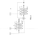
- Figure 2 is a schematic diagram showing an exemplary chemical liquid manufacturing apparatus adopted in a method for processing a chemical liquid in accordance with some embodiments.
- a method for processing a chemical liquid includes, in Step 10, providing a chemical liquid manufacturing apparatus 210 for producing a processed chemical liquid.
- the number of unwanted particulates (particles) and the amount of metallic impurities in the processed chemical liquid are limited within predetermined ranges.
- the chemical liquid manufacturing apparatus 210 comprises at least a first purification system 110.
- the chemical liquid manufacturing apparatus 210 comprises a second purification system 120 in addition to or in place of the at least first purification system 110.
- the first purification system 110 includes one or plural filtration media 114 (purification means), each having a specific purification function (mode or medium of a filtration unit) and offering a specific treatment.
- the purification system 110 may include at least one filtration medium 114 (114a, 114b or 114c) selected from a particle removal filter, an ion exchange membrane, and an ion adsorption membrane.
- the one or plural filtration media 114 are high-quality grade products that are commercially available from suppliers.
- the one or plural filtration media 114 may be compartmentalized and contained in one or plural housings 112, respectively.
- the first purification system 110 may include at least one housing 112 selected from a first housing 112a, a second housing 112b, a third housing 112c, and the at least one housing 112 includes and accommodates one or plural units of filtration medium 114 therein.
- the first purification system 110 may include just one housing 112 (either the first housing 112a, the second housing 112b, or the third housing 112c), or two housings 112 (a combination of any two of the first housing 112a, the second housing112b, and the third housing 112c), or three housings (the first housing 112a, the second housing112b, and the third housing 112c). It is noted that the above examples are for illustrative purposes, and the number of housings is not limited to the shown examples.
- the first housing 112a may include one or plural units of the first filtration medium 114a
- the second housing 112b may include one or plural units of the second filtration medium 114b
- the third housing 112c may include one or plural units of the third filtration medium 114c
- the first, second, and third filtration media 114a, 114b and 114c may be different in functionality or property, and offer different purification treatments, while the one or more units of the filtration medium 114 (114a, 114b, 114c) accommodated in each of the selected housings 112 (112a, 112b, 112c), respectively, have the same or similar purification function, physiochemical properties, pore size and/or construction material, etc.
- the first purification system 110 may include one or plural particle removal filters, one or plural ion exchange membranes, and one or plural ion adsorption membranes accommodated in the first housing 112a, the second housing 112b, and the third housing 112c, respectively.
- the first purification system 110 may include one or plural particle removal filters and one or plural ion exchange membranes accommodated in the first housing 112a and the second housings 112b, respectively.
- the first purification system 110 may include one or plural particle removal filters and one or plural ion adsorption membranes accommodated in the first housing 112a and the second housings 112b, respectively. It is noted that the above examples are for illustrative purposes and are not intended to be limiting.
- the number of units of filtration medium 114 (114a, 114b, 114c) accommodated respectively in each of the selected housings 112 (112a, 112b, 112c) is not limited.
- the number of units of filtration medium 114 accommodated in each of the selected housings 112 may range inclusively from one to thirty, for example, one, two, ten, fifteen, twenty, thirty or any range between any two of the preceding number of units.
- the number of units of filtration medium 114 may be above thirty. It is noted that the number of units of filtration medium 114 accommodated in each of the selected housings 112 is not limited to the shown examples.
- the method for processing a chemical liquid includes, in Step 20a, performing a treatment process on the first purification system 110 having one or more filtration media 114 with a treatment liquid prior to delivering a chemical liquid 220 to the first purification system 110 to be processed by the first purification system 110 of the chemical liquid manufacturing apparatus 210.
- the treatment process includes a washing process wherein innate impurities embedded in the filtration media 114 can be removed. More specifically, the one or more units of the filtration medium 114 (114a, 114b, 114c) accommodated in each of the selected housing(s) 112 (112a, 112b, 112c) are washed with a washing liquid 230. It is noted that the treatment process on the first purification system 110 is not limited as such.
- the washing liquid used in the washing process is not particularly limited, and well known washing liquids can be used.
- water and an organic solvent, in which particulates (particles), metallic impurities, and organic impurities are sufficiently reduced therein can be used.
- the chemical liquid itself or a liquid obtained by diluting the chemical liquid can be used as the washing liquid.
- the washing liquid is the same as at least one of the organic solvents contained in the chemical liquid to be processed, with the proviso that the at least one of the organic solvents is a high-purity product containing just a small amount of impurities.
- the content of iron (Fe) and calcium (Ca) in the washing liquid applied in the washing process is limited to about 10 ppb or less.
- washing liquid examples include, but not limited to, isopropanol, propylene glycol monomethyl ether (PGME), propylene glycol monomethyl ether acetate (PGMEA), propylene glycol monoethyl ether (PGEE), propylene glycol monopropyl ether (PGPE), ethyl lactate (EL), dimethyl sulfoxide (DMSO), n-methyl pyrrolidone (NMP), diethylene glycol (DEG), ethylene glycol (EG), dipropylene glycol (DPG), propylene glycol, propylene ethylene carbonate, propylene carbonate, sulfolane, cyclohexane, cyclohexanone (CyH), cycloheptanone (CyHe), cyclopentanone (CyPe), 2-heptanone, ⁇ -butyrolactone.
- two or more different types of these organic solvents may be mixed and used as a cleaning liquid, or may be
- the method of the washing is not particularly limited.
- the washing process includes flushing or rinsing with a generous quantity of fluid. More specifically, the one or more units of the filtration medium 114 (114a, 114b, 114c) accommodated in each of the selected housing(s) 112 (112a, 112b, 112c) is flushed with a washing liquid 230.
- a predetermined amount of the washing liquid 230 is dispensed into a first housing of the selected housings 112 (112a, 112b, 112c) which are concatenated together, and the washing liquid 230 is caused to flow or cascade through the filtration media 114 in each of the selected housings 112 (112a, 112b 112c), so that each unit of the filtration media 114 will come in full contact with the washing liquid, and any innate impurities lodged or embedded in the filtration media 114 will be carried away by the washing liquid 230.
- the washing liquid 230 then exits the last housing (for example the third housing 112c) of the selected housings 112 and is collected in a discharge tank 130.
- the washing liquid 230 is conveyed to the first housing in the first purification system 110 via a conduit separated from a conduit for delivering a chemical liquid 220 to the chemical liquid manufacturing apparatus 210 for processing.
- the above examples are for illustrative purposes and are not intended to be limiting.
- the washing liquid 230 and the chemical liquid 220 may be delivered to the first purification system 110 of the chemical liquid manufacturing apparatus 210 via a same conduit.
- the amount of the washing liquid used in a washing or flushing process is not particularly limited.
- a practical amount of washing liquid adopted in a washing or flushing process in some embodiments of the disclosure may range inclusively from 19 to 1893 L (5 to 500 gallons) per each housing 112 per one washing cycle (one time of washing); for example, the amount of washing liquid may be about 19, 38, 76, 379, 757, 1136, 1514, 1893 L (5, 10, 20, 50 , 100, 200, 300, 400, 500 gallons) per housing 112 per washing cycle, including any range between any two of the preceding amounts.
- washing liquid 230 is dispensed into the first purification system 110 per one washing cycle. More specifically, about 114 L (30 gallons) of the washing liquid 230 is dispensed into the first housing 112a.
- the washing liquid 230 then travels in a forward flow direction from the first housings 112a to the second housing 112b and finally drains from the third housing 112c into the discharge tank 130, so that each unit of the filtration media (114a, 114b, 114c) in each of the housings (112a, 112b, 112c) is flushed and washed with the washing liquid 230.
- the number of housings 112 of filtration media 114 to be treated or washed is not limited to the shown examples.
- the number housings 112 of filtration media 114 to be treated or washed may be, for example, 1, 2, 5, or 10, and the amount washing liquid used is correspondingly 38, 76, 189 or 379 L (10, 20,50 or 100 gallons) per one washing cycle.
- the above exemplary amount of 38 L (10 gallons) of washing liquid per housing per washing cycle is for illustrative purposes and is not intended to be limiting.
- the amount of washing liquid used per housing per washing cycle may vary in accordance with the source, the type, and the initial condition of the filtration media 114 (114a, 114b, 114c), for example, 114, 208, 568 or 1514 L (30 gallons, 55 gallons, 150 gallons or 400 gallons) of washing liquid may be adopted per housing per washing cycle.
- the initial condition of the filtration media 114 is the condition in which the filtration media 114 are obtained, for example, from the supplier.
- washing or flushing of the filtration media 114 is a single process (1X), and a chemical liquid 220 is delivered to the first purification system 110 to be processed after the single washing or flushing process is completed.
- the washing or flushing may be performed for plural cycles (times), for example, two (2X), three (3X), four (4X), six (6X), or eight (8X) cycles, wherein a fresh batch of washing liquid is used for each cycle.
- fresh batch of washing liquid means a washing liquid that has not been used previously in the washing or flushing process, and a content of iron (Fe) and calcium (Ca) in the washing liquid is about 10 ppb or less.
- a totality of the washing liquid intended for all the washing cycles combined is applied collectively to wash or flush the filtration media 114 in the housings 112.
- the washing or flushing process of two cycles as exemplified above may be achieved by applying a total of 227 L (60 gallons) of washing liquid 230 as a whole to wash or flush the filtration media 114 (114a, 114b, 114c) in each housing 112 of the three housings (112a, 112b, 112c).
- the chemical liquid manufacturing apparatus 210 may further include a second purification system 120 which communicates with the first purification system 110 either directly or indirectly, wherein the second purification system 120 includes one or plural filtration media 124.
- the second purification system 120 is configured downstream from the first purification system 110; however, it is noted that the relative configuration of the first purification system 110 and the second purification system 120 is not limited to the shown examples above.
- the one or plural filtration media 124 in the second purification system 120 may be compartmentalized and contained in one or plural housings 122, respectively.
- the second purification system 120 may include at least one housing 122 selected from a fourth housing 122a, a fifth housing 122b and a sixth housing 122c, and the at least one housing 122 includes and accommodates one or plural units of filtration medium 124 therein.
- the second purification system 120 may include one, two, or three housings 122.
- the second purifying system 120 may include more housings 122, for example, one, two, five, or ten more, in addition to the fourth housing 122a, the fifth housing 122b and the sixth housing 122c. Further, there may be no separate housings 122, and the one or plural filtration media 124 are configured un-compartmentalized in the second purification system 120. In yet other exemplary embodiments, the second purification system 120 also may include other unillustrated material treatment modules, in addition to the one or plural filtration media 124.
- the fourth housing 122a may include one or plural units of the fourth filtration medium 124a
- the fifth housing 122b may include one or plural units of the fifth filtration medium 124b
- the sixth housing 122c may include one or plural units of the sixth filtrations medium 124c, wherein the fourth filtration medium 124a, the fifth filtration medium 124b, and the sixth filtration medium 124c may be different in functionality or property, and offer different purification treatments, while the one or more units of the filtrations medium 124 (124a, 124b, 124c) accommodated in each of the selected housings 122 (122a, 122b, 122c), respectively, have the same or similar purification function, physiochemical properties, pore size and/or construction material, etc.
- the second purification system 120 may include at least one filtration medium 124 (124a, 124b, 124c) selected from a particle removal filter, an ion exchange membrane and an adsorption membrane.
- the second purification system 120 may include three particle removal filters accommodated in the fourth housing 122a, and three ion exchange membranes or three ion adsorption membranes accommodated in the fifth housing 122b.
- the second purification system 120 may include two, three or four particle removal filters accommodated in the fourth housing 122a and another two, three or four particle removal filters accommodated in the fifth housing 122b, wherein the particles removal filters in the two housings 122a, 122b are different in terms of pore size and/or construction material.
- the one or plural filtration media 124 are high-purity grade products that are commercially available and obtained fresh from suppliers.
- the number of units of filtration medium 124 (124a, 124b, 124c) accommodated respectively in each of the selected housings 122 (122a, 122b, 122c) is not limited. In some embodiments, the number of units of filtration medium 124 accommodated in each of the selected housings 122 may range inclusively from one to thirty, for example, one, two, ten, fifteen, twenty, thirty, or any number between any two of the preceding number of units. In alternative embodiments, the number of units of filtration medium 124 may be above thirty. It is noted that the number of units of filtration medium 124 accommodated in each of the selected housings 122 is not limited to the shown examples.
- the method for processing a chemical liquid also includes, in Step 20b, performing a treatment process on the second purification system 120 having one or more filtration media 124 with a treatment liquid prior to the processing of a chemical liquid with the chemical liquid manufacturing apparatus 210 of the present disclosure.
- the principles of the treatment process applied to the second purification system 120 are similar to those applied to the first purification system 110 as exemplified in paragraphs [0055] to [0072].
- the treatment process performed on the second purification system 120 may include a washing process. More specifically, in Step 20b, the one or more units of the filtration medium 124 (124a, 124b, 124c) accommodated in each of the selected housing(s) 122 (122a, 122b, 122c) of the second purification system 20 are washed with a washing liquid 40.
- a predetermined amount of washing liquid 40 is dispensed into a first housing of the selected housings 122 in the second purification system 120 to wash or flush the one or more units of the filtration medium 124 (124a, 124b, 124c) accommodated in each of the selected housing(s) 122 (122a, 122b, 122c), which are concatenated together in the second purification system 120.
- the washing liquid 40 is caused to flow or cascade through the filtration media 124 in each of the selected housings 122, so that each unit of the filtration media 124 comes in full contact with the washing liquid, and innate impurities embedded or lodged in the filtration media 124 will be rinsed away by the washing liquid 40.
- the washing liquid 40 then exits from the last housing (for example, the sixth housing 122c) of the selected housing(s) 122 and is collected in a discharge tank 150. It is noted that above exemplary treatment process applied to the second purification system 120 is for illustrative purposes and is not intended to be limiting.
- the processing of a chemical liquid 220 is implemented in Step 30 by adopting the chemical liquid manufacturing apparatus 210 of the present disclosure.
- the processing of a chemical liquid in Step 30 includes, for example, performing a purification process on the chemical liquid 220 using the post-treated first purification system 110 and/or the post-treated second purification system 120 installed in the chemical liquid manufacturing apparatus 210.
- the treatment of the first purification system 110 and the treatment of the second purification system 120 are executed individually and separately, but may be implemented concurrently or sequentially. More specifically, the type(s) of treatment liquid, the treatment conditions, the amount(s) of treatment liquid used, the number(s) of treatment cycles, the treatment methods (flushing, immersing, or both), etc. applied to treat the filtration media 114 of first purification system 110 and those applied to treat the filtration media 124 of the second purification system 120 may be the same as, similar to or may vary from each other, depending on the sources, the types, and the conditions of the filtration media 114 and 124, and the numbers of selected housings 112 and 122 to be treated in the respective purification system 110, 120.
- cyclohexanone may be used as a washing liquid 230 for treating the filtration media 114 of first purification system 110, and as a washing liquid 40 for treating the filtration media 124 of the second purification system 120; however, the treatment conditions and the number of treatment cycles mandated for treating the filtration media 114 may be different from the treatment conditions and the number of treatment cycles mandated for treating the filtration media 124. Moreover, the treatment of the first purification system 110 may be performed before, after, or simultaneously with the treatment of the second purification system 120.
- fresh batches of cyclohexanone are applied to first purification system 110 and the second purification system, respectively, and a fresh batch of cyclohexanone is applied for each treatment cycle for the treatment of the purification systems 110 and 120, respectively. It is noted that the above examples are for illustrative purposes and are not intended to be limiting.
- the treatment process is performed under ambient condition (room temperature and atmospheric pressure).
- the treatment condition is a function of the filtration media (114, 124) and/or the treatment liquids used for the treatment thereof.
- the treatment condition is controlled to below or above the ambient condition.
- the washing or flushing of a certain ion exchange membrane or ion adsorption membrane is executed below room temperature, such as below 2.7 °C (80 °F) or below 25 °C (77 °F) when certain cyclic aliphatic ketone organic solvents are used as a washing liquid.
- the washing or flushing of an ion exchange membrane is executed below 25 °C (77 °F) when cyclohexanone (CyH) is applied as a washing liquid.
- the flow rate of a washing liquid flowing or passing through the filtration media 114, 124 is typically controlled to be slower than a normal operating flow rate of about 38 to 45 L (10 to 12 gallons)/minute when a chemical liquid 220 is processed.
- the flow rate of a washing liquid during a washing or flushing process may range from as low as about 3.8 L (1 gallon)/ minute up to about 38 L (10 gallons)/ minute for example, about 3.8, 7.6, 19 or 8 L (1, 2, 5, or 8 gallons)/ minute
- the flow rate may exceed 38 L (10 gallons) minute for example, 68 to 76 L (18 to 20 gallons)/ minute
- the treatment process is performed in-situ to the one or more units of the filtration medium (114, 124) in each of the selected housing(s) (112, 122) that are configured in the purification system (110, 120), installed already in the chemical liquid manufacturing apparatus 210.
- an off-line treatment process may be carried out.
- the off-line treatment process is substantially equivalent to the in-situ treatment process discussed above with a major difference in that each of the elected housing(s) (112, 122) having the one or more units of the filtration medium (114, 124) accommodated therein is subjected to a treatment process, as exemplified above in paragraphs [0060] to [0072] and [0077] to [0079], before the elected housing(s) (112, 122) are configured in the purification system (110, 120), respectively and installed in the chemical liquid manufacturing apparatus 210.
- a treatment process is performed on each of the selected housing(s) (112) having one or more units of the filtration medium 114 therein in Step 10a, wherein the treatment process may be the same or different for each of the selected housing(s) (112).
- a treatment process is performed on each of the selected housing (122) having one or more units of the filtration medium 124 therein in step 10b, wherein the treatment process may be the same or different for each of the selected housing(s) (122).
- Step 10b the elected housing(s) 112 are configured together as a post-treated first purification system 110, and the elected housing(s) 122 are configured together as a post-treated second purification system 120, which are to be installed in a chemical liquid manufacturing apparatus 210 in Step 20.
- the processing of a chemical liquid 220 is implemented in Step 30 by adopting the post-treated first purification system 110 and the post-treated second purification system 120 configured in the chemical liquid manufacturing apparatus 210 of the present disclosure.
- the particle removing process is a process of removing particles and/or metal impurities (metal impurities in a solid form) in a processing target, such as a chemical liquid, by using a particle removal filter.
- the particle removal filter is not particularly limited, and well-known particle removal filters can be used.
- the average pore size (pore diameter) of the filter is not particularly limited, it is suitably about 0.001 to 1.0 ⁇ m (1 nm to 1000nm), preferably about 0.003 to 0.5 ⁇ m (3nm to 500nm), and more preferably about 0.005 to 0.1 ⁇ m (5nm to 100nm). Within this range, it is possible to reliably remove foreign matters such as impurities or aggregates contained in the refined product while suppressing clogging of the filter.
- the first purification system 110 may include a particle removal filter having an average pore size as small as 2nm (for example, microfiltration membrane having a pore size of 2 nm or greater), and may range from 0.002 ⁇ m (2nm) or more to about 1.0 ⁇ m (1000nm) or less.
- the processing target is filtered by using a filter having an average pore size as small as 50 nm to remove particles before filtering is performed by using a filter having average pore size as small as 20 nm or 15 nm to remove finer particles.
- the filtration efficiency is improved and performance of removing particles is more improved.
- the second purification system 120 may include a particle removal filter having a pore size as small as 0.001 ⁇ m (1nm), and may range from about 0.001 ⁇ m (1nm) or more to about 0.015 ⁇ m (15nm) or less.
- the second purification system 120 may include a UPE filter having a pore size as small as 1nm.
- the second purification system 120 may include a Nylon or a MPTFE filter having a pore size of about 5nm.
- the average pore size can refer to the nominal value of the filter manufacturer.
- Examples of the material of the filter used in particle removal include a fluororesin such as polytetrafluoroethylene (PTFE), a polyamide resin such as nylon and the like, a polyolefin resin (including high density and ultrahigh molecular weight) such as polyethylene and polypropylene (PP) and the like, a perfluoroalkoxy (PFA) resin and the like, or a modified polytetrafluoroethylene (MPTFE).
- PTFE polytetrafluoroethylene
- a polyamide resin such as nylon and the like
- a polyolefin resin including high density and ultrahigh molecular weight
- PP polyethylene and polypropylene
- PFA perfluoroalkoxy
- MPTFE modified polytetrafluoroethylene
- the filter used in particle removal of the present disclosure is made of at least one selected from the group consisting of nylon, polypropylene (including high density polypropylene), polyethylene, polytetrafluoroethylene, tetrafluoroethylene-perfluoroalkyl vinyl ether copolymer, polyimide, and polyamdie imide. According to the filter made of the above material, it is possible to effectively remove foreign matter having high polarity which is likely to cause residue defects and/or particle defects, and it is possible to efficiently reduce the content of the metal component in the chemical liquid.
- Polyimide and/or polyamide imide may have at least one selected from the group consisting of a carboxy group, a salt type carboxy group, and a -NH-bond. Regarding solvent resistance, a fluororesin, polyimide, and/or polyamide imide is excellent.
- filters manufactured by Pall Corporation, ADVANTEC Toyo Roshi Kaisha, Ltd., Entegris Japan Co., Ltd. (former Nihon microlith Corporation) and KITZ MICRO FILTER CORPORATION can be selected from various filters to be provided.
- a "P-Nylon filter (pore size of 0.02 ⁇ m and critical surface tension of 77 mN/m)" manufactured by Pall Corporation) made of polyamide
- a "PE ⁇ clean filter (pore size of 0.02 ⁇ m)” manufactured by Pall Corporation) made of high-density polyethylene
- a "PE ⁇ clean filter (pore size of 0.01 ⁇ m)” manufactured by Pall Corporation) made of high-density polyethylene
- UEE pore size of 3nm
- the ion-exchange resin membrane used in the present embodiment is not particularly limited, and filters including an ion-exchange resin comprising a suitable ion-exchange group immobilized to a resin membrane may be used.
- ion-exchange resin membranes include strongly acidic cation-exchange resins comprising a cation-exchange group such as a sulfonic acid group chemically modified on the resin membrane, and examples thereof include cellulose, diatomaceous earth, nylon (a resin having an amide group), polyethylene, polypropylene, polystyrene, a resin having an imide group, a resin having an amide group and an imide group, a fluororesin, or a high-density polyethylene membrane with ion-exchange resin membranes and a particle-removing membrane that is a membrane having an integral structure of a particle-removing membrane and an ion-exchange resin membrane.
- the ion adsorption membrane has a porous membrane material and has an ion exchange function.
- Such ion adsorption membrane is not particularly limited as long as it has a pore diameter of 100 ⁇ m or less and has an ion exchange function.
- the material, the type and the like thereof are not particularly limited.
- Examples of the material of a base material constituting the ion adsorption membrane include, but not limited to, cellulose, diatomaceous earth, film material of microfiltration membrane such as nylon (resin having amide group), polyethylene, polypropylene, polystyrene, resin having imide group, resin having amide group and imide group, fluororesin, or high density polyethylene resin, a membrane material having an ion exchange ability functional group introduced therein, or the like.
- Examples of the shape of the membrane material include a pleated type, a flat membrane type, a hollow fiber type, a porous body as described in JP-A No. 2003-112060 and the like.
- the ion exchange group to be introduced into the membrane material it is preferable to use a combination of at least two of the cation exchange group, the chelate exchange group, and the anion exchange group to optimize the elution and selectivity of the components to be removed. Since the ion adsorption membrane has porosity, it is also possible to remove a part of the fine particles.
- the ion adsorption membrane is, for example, a nylon membrane having a pore diameter as small as 0.02 ⁇ m (20nm).
- the selection of the filtration media 114 in the first purification system 110, the number of washing cycles, and the amount of washing liquid applied to treat the selected filtration media were adjusted to obtain a post-treatment washing liquid having a composition in each of the samples at the end of each washing cycle.
- the filtration media used in the following experiments were high-quality grade products obtained brand new from suppliers. In some of the experiments multiple units of the filters were flushed at one time, but the data presented below were mathematically normalized to a single unit.
- Each post-treatment washing liquid sample was collected and then inserted into a wafer coating tool. After a bare wafer was coated with a sample, the wafer was transferred to and inspected by a laser-based inspection system. By using a laser light, the laser-based inspection system detected, counted, recorded the location and sizes each particle on the wafer, at a detection limit of 19nm. More specifically, counting targets included particles having a size of 19nm or greater.
- the data was used to create wafer maps and provide the total on-wafer particle counts (OWPC), which included all particles having a size of 1000nm and below. SP5 was a subset of the OWPC which included particles having a size of about 19nm to about 23nm.
- the wafer was then transferred to be inspected by EDX (energy dispersive x-ray). Each particle reported by the laser-based inspection system was inspected by EDX (energy dispersive x-ray) for providing the elemental information. Any particle, which was found to produce any metal signal, was counted as a metal particle. The total number of particles with a metal signature was totalized to report as OWMP (on-wafer metal particle) or OWMC (on-wafer metal count).
- EDX energy dispersive x-ray
- a flushing process according to the present disclosure was performed on the first purification system comprising ultra-high MW polyethylene particle (UPE) removal filter(s) having a pore size of 3nm.
- the washing liquid used was cyclohexanone in the amount of about 38 to 189 L (10 to 50 gallons) per flush, and the washing liquid was caused to flush or pass through the UPE filter under ambient temperature and an inlet pressure up to 3.4 bar (pounds per square inch).
- a sample was collected at the end of each of the four cycles of flushing (1st flush, 2nd flush, 3rd flush, and 4th flush).
- the OWPC, OWMC (or OWMP), and counts of selected metal elements in each sample were measured and the normalized data were summarized in Table 1.
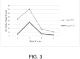
- FIG. 3 also graphically illustrates the OWMC results.
- Washing liquid Cyclohexanone Amount of washing liquid in each flush: 38 L (10 gallons)
- Filter type UPE (ultra-high MW polyethylene) Pore size: 3nm 1st flush 2nd flush 3rd flush 4th flush Amount of washing liquid (gallons) 10 gallons 10 gallons 10 gallons 10 gallons OWMC 45 71 18 11 Ti 1 0 0 1 Fe 8 9 12 1 Mg 6 5 4 0 Al 27 13 1 1 Zn 3 41 0 6
- the treatment process of the present application was shown to have achieved the desired advantages of significantly reducing the OWMC and counts on the selected metal elements for the UPE filter.
- the data also indicated that the effects of the treatment process were even more pronounced after the 3rd flush.
- the OWMC was reduced by fourfold, compared to the OWMC after the 1 st flush.
- the counts of the various selected metal elements, such as Al, Fe, Mg, etc. also significantly diminished by the end of the 4 th flush.
- a flushing process according to the present disclosure was performed under ambient temperature and an inlet pressure up to 3.4 bar (50 psig) on a purification system comprising HDPE (high density polyethylene) particle removal filter(s) having a pore size of 2nm.
- the washing liquid used in this flushing process was cyclohexanone. Two separate tests were performed, wherein during the 2 nd test, the amount of the washing liquid used was four times the amount used in the 1 st test. A sample was collected at the end of the flushing of each of the 1 st and 2 nd tests.
- the OWPC, the SP5, the OWMC, and the counts on selected metal elements in each sample were measured and the normalized data were summarized in Table 3.
- the count of particles having a size of about 19nm to about 23nm from a pretreated HDPE filter was greater than 10000.
- Washing Liquid PGMEA (Propylene glycol monomethyl ether acetate)
- Filter type PTFE (Polytetrafluoroethylene)
- Pore size 10nm Flushing Test Test 1 Initial Flush (1X) Test 2 8 Times Flush (8X) Flushing amount (gallons/20" media) 406 OWPC (1000nm and below) >500,000 1354 SP5 (19-23nm) OWMC (total) saturated 6 Al Ti Fe saturated 4 Ni Co Cu
- the data as shown in Table 4 further confirmed the notable effects of a substantial reduction in the OWPC and the OWMC after a treatment process of the present disclosure was performed on a PTFE filter. More particularly, the OWPC was significantly reduced from being greater than 500,000 to slightly above 1000 after increasing the amount of washing liquid from about 189 to 1514 L (50 to 400 gallons) (or increasing from a single flush cycle to 8 flush cycles). The data also indicated that the OWMC and the Fe count were reduced dramatically from being saturated on the wafer to a single digit (6 and 4, respectively) after increasing the amount of washing liquid by eightfold.
- the data obtained in Table 5 was obtained using the treatment liquid PGMEA (propylene glycol monomethyl ether acetate).
- the data in this table demonstrates the effect of soaking the filtration medium in the treatment liquid for a time period of about 16 hours, followed by a flush with 50 kg of the treatment liquid. More specifically, the filtration medium was submerged in the treatment liquid overnight at ambient conditions. Thereafter, the filtration medium was placed in the filter housing and was flushed with fresh treatment liquid. As readily seen, soaking prior to flushing of the filtration medium provides a marked improvement in OWPC ⁇ 31 ( ⁇ 31 nm bin size particles) and OWMC.
- the soaking process is be performed for 3 to 5 periods, wherein each period may range from about 12 to 18 hours. More specifically, the filtration media are placed in a container and submerged in the same type of the treatment liquid to be used in the subsequent treatment process. At the end of each soaking period, the treatment liquid is drained, and fresh treatment liquid is provided for the next soaking period. After the soaking process is completed, the treatment process is commenced to flush the filtration media.
Landscapes
- Chemical & Material Sciences (AREA)
- Chemical Kinetics & Catalysis (AREA)
- Engineering & Computer Science (AREA)
- Water Supply & Treatment (AREA)
- Nanotechnology (AREA)
- Analytical Chemistry (AREA)
- Separation Using Semi-Permeable Membranes (AREA)
- Photosensitive Polymer And Photoresist Processing (AREA)
- Solid-Sorbent Or Filter-Aiding Compositions (AREA)
- Cleaning Or Drying Semiconductors (AREA)
Claims (18)
- Un procédé de traitement d'un liquide chimique (220) comprenant un solvant organique, comprenant :le fait de fournir un système de purification (110) comprenant au moins un moyen de filtration (114), choisi parmi un filtre d'élimination de particules, une membrane échangeuse d'ions et une membrane d'adsorption d'ions ;le fait de mettre en œuvre un processus de trempage en plaçant ledit au moins un moyen de filtration (114) dans un récipient et en trempant ledit au moins un moyen de filtration (114) dans un liquide stocké dans le récipient pendant au moins une période de trempage de 12 à 18 heures ; trois à cinq périodes de trempage sont mises en oeuvre ;après le processus de trempage, le fait de mettre en œuvre un processus de traitement sur le système de purification (110) en faisant passer un liquide de traitement (230) à travers ledit au moins un moyen de filtration (114) du système de purification (110), une teneur totale en fer (Fe) et en calcium (Ca) dans le liquide de traitement (230) étant de 0 ppb ou plus et de 10 ppb ou moins, le liquide utilisé dans le processus de trempage étant le même que le liquide de traitement (230), et le liquide de traitement (230) est le même qu'au moins l'un des solvants organiques contenus dans le liquide chimique (220) à traiter ; etaprès le processus de traitement, le fait de traiter le liquide chimique (220) avec le système de purification (110) configuré dans un appareil (210) de fabrication de liquide chimique,l'appareil (210) de fabrication de liquide chimique comprenant le système de purification (110), et un liquide chimique traité est obtenu en introduisant le liquide chimique (220) dans l'appareil (210) de fabrication de liquide chimique et en faisant passer le liquide chimique (220) à travers le système de purification (110).
- Le procédé selon la revendication 1, dans lequel le système de purification (110) est configuré dans l'appareil (210) de fabrication de liquide chimique après que le processus de traitement a été mis en œuvre.
- Le procédé selon la revendication 1, dans lequel le système de purification (110) est configuré dans l'appareil (210) de fabrication de liquide chimique avant que le processus de traitement ne soit mis en œuvre.
- Le procédé selon la revendication 1, dans lequel le processus de traitement est mis en œuvre une ou plusieurs fois.
- Le procédé selon la revendication 1, dans lequel le procédé de traitement est mis en œuvre sur le système de purification (110) comprenant au moins deux moyens de filtration (114), choisis parmi le filtre d'élimination des particules, la membrane échangeuse d'ions et la membrane d'adsorption d'ions.
- Le procédé selon la revendication 1, dans lequel le procédé de traitement est mis en œuvre sur le système de purification (110) comprenant un parmi le filtre d'élimination de particules et la membrane échangeuse d'ions ou un parmi le filtre d'élimination de particules et la membrane d'adsorption d'ions.
- Le procédé selon la revendication 1, dans lequel ledit au moins un moyen de filtration (114) comprend un filtre en polytétrafluoroéthylène (PTFE) ayant une taille de pores de 50nm ou moins.
- Le procédé selon la revendication 1, dans lequel ledit au moins un moyen de filtration (114) comprend un filtre en polytétrafluoroéthylène (PTFE) ayant une taille de pores de 10nm ou moins.
- Le procédé selon la revendication 1, dans lequel une condition de traitement du processus de traitement est une fonction dudit au moins un premier moyen de filtration (114) et du liquide de traitement (230) et est commandée de façon à être à moins de 27°C (80°F).
- Le procédé selon la revendication 1, comprenant :
le fait de mettre en œuvre un processus de purification en traitant le liquide chimique (220) avec le système de purification (110) configuré dans l'appareil (210) de fabrication de liquide chimique. - Le procédé selon la revendication 10, dans lequel l'étape d'application du liquide de traitement (230) comprend le fait de faire s'écouler le liquide de traitement (230) dans le système de purification (110).
- Le procédé selon la revendication 10, comprenant en outre :le fait de fournir un deuxième système de purification (120) comprenant au moins un deuxième moyen de filtration (124), choisi parmi un deuxième filtre d'élimination de particules, une deuxième membrane échangeuse d'ions et une deuxième membrane d'adsorption d'ions ; etle fait de mettre en œuvre un processus de traitement sur le deuxième système de purification (120) en appliquant un deuxième liquide de traitement (40) audit au moins un deuxième moyen de filtration (124) du deuxième système de purification (120) avant que le processus de purification ne soit mis en œuvre, une teneur totale en fer (Fe) et en calcium (Ca) dans le deuxième liquide de traitement (40) étant de 0 ppb ou plus et inférieure à 10ppb, et le deuxième liquide de traitement (40) étant le même qu'au moins un des solvants organiques contenus dans le liquide chimique (220) à traiter,le processus de traitement du système de purification (110) et le processus de traitement du deuxième système de purification (120) étant mis en œuvre individuellement et séparément,l'appareil (210) de fabrication de liquide chimique comprenant en outre le deuxième système de purification (120), et le liquide chimique traité étant obtenu en introduisant le liquide chimique (220) dans l'appareil (210) de fabrication de liquide chimique et en faisant passer le liquide chimique (220) à travers le système de purification (110) et le deuxième système de purification (120).
- Le procédé selon la revendication 12, dans lequel l'étape d'application du deuxième liquide de traitement (40) comprend le fait de faire s'écouler le deuxième liquide de traitement (40) dans le deuxième système de purification.
- Le procédé selon la revendication 12, dans lequel le processus de purification est mis en œuvre sur le liquide chimique (220) avec le deuxième système de purification (120) configuré dans l'appareil (210) de fabrication de liquide chimique.
- Le procédé selon la revendication 12, dans lequel le système de purification (110) et le deuxième système de purification (120) sont configurés dans l'appareil (210) de fabrication de liquide chimique après les étapes d'application du liquide de traitement (230) et du deuxième liquide de traitement (40).
- Le procédé selon la revendication 12, dans lequel le système de purification (110) et le deuxième système de purification (120) sont configurés dans l'appareil (210) de fabrication de liquide chimique avant les étapes d'application du liquide de traitement (230) et du deuxième liquide de traitement (40).
- Le procédé selon la revendication 12, dans lequel l'étape d'application du liquide de traitement (230) et l'étape d'application du deuxième liquide de traitement (40) sont chacune mises en œuvre une fois.
- Le procédé selon la revendication 12, dans lequel un nombre de fois d'application du liquide de traitement (230) est différent d'un nombre de fois que le deuxième liquide de traitement (40) est appliqué.
Applications Claiming Priority (2)
| Application Number | Priority Date | Filing Date | Title |
|---|---|---|---|
| US201862720890P | 2018-08-21 | 2018-08-21 | |
| PCT/US2019/047367 WO2020041388A1 (fr) | 2018-08-21 | 2019-08-21 | Procédé de traitement d'un liquide chimique |
Publications (3)
| Publication Number | Publication Date |
|---|---|
| EP3840876A1 EP3840876A1 (fr) | 2021-06-30 |
| EP3840876A4 EP3840876A4 (fr) | 2022-06-08 |
| EP3840876B1 true EP3840876B1 (fr) | 2025-03-12 |
Family
ID=69587012
Family Applications (1)
| Application Number | Title | Priority Date | Filing Date |
|---|---|---|---|
| EP19852776.4A Active EP3840876B1 (fr) | 2018-08-21 | 2019-08-21 | Procédé de traitement d'un liquide chimique |
Country Status (9)
| Country | Link |
|---|---|
| US (1) | US11541358B2 (fr) |
| EP (1) | EP3840876B1 (fr) |
| JP (1) | JP7628075B2 (fr) |
| KR (1) | KR102906040B1 (fr) |
| CN (1) | CN112638517A (fr) |
| IL (1) | IL280551B2 (fr) |
| SG (1) | SG11202100982SA (fr) |
| TW (1) | TWI887206B (fr) |
| WO (1) | WO2020041388A1 (fr) |
Families Citing this family (2)
| Publication number | Priority date | Publication date | Assignee | Title |
|---|---|---|---|---|
| TW202146365A (zh) * | 2020-03-27 | 2021-12-16 | 美商富士軟片電子材料美國股份有限公司 | 用於純化溶劑之系統及方法 |
| US20250313752A1 (en) * | 2022-05-19 | 2025-10-09 | Shin-Etsu Chemical Co., Ltd. | Method for producing aqueous solution of purified aminosilanol compound and aminosiloxane compound, and composition for etching |
Family Cites Families (13)
| Publication number | Priority date | Publication date | Assignee | Title |
|---|---|---|---|---|
| US4778532A (en) * | 1985-06-24 | 1988-10-18 | Cfm Technologies Limited Partnership | Process and apparatus for treating wafers with process fluids |
| US5733441A (en) | 1996-06-27 | 1998-03-31 | United Microelectronics Corporation | Pre-wet system for a filter |
| JP3673393B2 (ja) * | 1998-03-09 | 2005-07-20 | オルガノ株式会社 | 超純水製造用イオン吸着膜の再生方法及び超純水の製造方法 |
| JP2001353424A (ja) | 2000-06-14 | 2001-12-25 | Fuji Photo Film Co Ltd | 半導体集積回路用ウエハー洗浄液のろ過方法 |
| JP4810757B2 (ja) | 2001-06-05 | 2011-11-09 | 栗田工業株式会社 | 超純水製造用限外ろ過膜およびその予備洗浄方法 |
| JP3761457B2 (ja) | 2001-12-04 | 2006-03-29 | Necエレクトロニクス株式会社 | 半導体基板の薬液処理装置 |
| JP2004330056A (ja) * | 2003-05-07 | 2004-11-25 | Ebara Corp | 電子素子基板表面処理液用フィルターカートリッジ |
| SG189051A1 (en) * | 2010-09-27 | 2013-05-31 | Tama Chemicals Co Ltd | Refining method for alkaline treatment fluid for semiconductor substrate and refining device |
| JP5762860B2 (ja) * | 2011-07-15 | 2015-08-12 | オルガノ株式会社 | アルコールの精製方法及び装置 |
| KR101715811B1 (ko) * | 2013-11-12 | 2017-03-13 | 주식회사 아모그린텍 | 이온 교환 멤브레인 |
| US9360758B2 (en) * | 2013-12-06 | 2016-06-07 | Taiwan Semiconductor Manufacturing Company, Ltd. | Semiconductor device process filter and method |
| JP7084683B2 (ja) * | 2015-02-23 | 2022-06-15 | 東京応化工業株式会社 | 液体の精製方法、薬液又は洗浄液の製造方法、フィルターメディア、及び、フィルターデバイス |
| WO2018043697A1 (fr) * | 2016-09-02 | 2018-03-08 | 富士フイルム株式会社 | Procédé et dispositif de purification de solvant organique |
-
2019
- 2019-08-21 WO PCT/US2019/047367 patent/WO2020041388A1/fr not_active Ceased
- 2019-08-21 CN CN201980054173.2A patent/CN112638517A/zh active Pending
- 2019-08-21 KR KR1020217004451A patent/KR102906040B1/ko active Active
- 2019-08-21 JP JP2021509148A patent/JP7628075B2/ja active Active
- 2019-08-21 US US16/546,315 patent/US11541358B2/en active Active
- 2019-08-21 TW TW108129858A patent/TWI887206B/zh active
- 2019-08-21 SG SG11202100982SA patent/SG11202100982SA/en unknown
- 2019-08-21 IL IL280551A patent/IL280551B2/en unknown
- 2019-08-21 EP EP19852776.4A patent/EP3840876B1/fr active Active
Also Published As
| Publication number | Publication date |
|---|---|
| TWI887206B (zh) | 2025-06-21 |
| US11541358B2 (en) | 2023-01-03 |
| JP7628075B2 (ja) | 2025-02-07 |
| KR20210044786A (ko) | 2021-04-23 |
| TW202019551A (zh) | 2020-06-01 |
| IL280551B1 (en) | 2025-05-01 |
| IL280551A (en) | 2021-03-25 |
| CN112638517A (zh) | 2021-04-09 |
| US20200061544A1 (en) | 2020-02-27 |
| SG11202100982SA (en) | 2021-02-25 |
| EP3840876A4 (fr) | 2022-06-08 |
| KR102906040B1 (ko) | 2025-12-29 |
| EP3840876A1 (fr) | 2021-06-30 |
| WO2020041388A1 (fr) | 2020-02-27 |
| IL280551B2 (en) | 2025-09-01 |
| JP2021533986A (ja) | 2021-12-09 |
Similar Documents
| Publication | Publication Date | Title |
|---|---|---|
| JP7831940B2 (ja) | 化学液体製造装置 | |
| JP2025023205A (ja) | 溶媒を精製するためのシステム及び方法 | |
| IL296812A (en) | Solvent purification systems and methods | |
| US11541358B2 (en) | Method for processing chemical liquid | |
| US11541335B2 (en) | Chemical liquid purification apparatus and purification method using the same | |
| JP2021533986A5 (fr) | ||
| US20230330627A1 (en) | Systems and Methods for Purifying Solvents | |
| EP3883663B1 (fr) | Appareil et procédé de production de liquide chimique | |
| TWI882967B (zh) | 化學液體製造裝置以及製造化學液體之方法 |
Legal Events
| Date | Code | Title | Description |
|---|---|---|---|
| STAA | Information on the status of an ep patent application or granted ep patent |
Free format text: STATUS: THE INTERNATIONAL PUBLICATION HAS BEEN MADE |
|
| PUAI | Public reference made under article 153(3) epc to a published international application that has entered the european phase |
Free format text: ORIGINAL CODE: 0009012 |
|
| STAA | Information on the status of an ep patent application or granted ep patent |
Free format text: STATUS: REQUEST FOR EXAMINATION WAS MADE |
|
| 17P | Request for examination filed |
Effective date: 20210127 |
|
| AK | Designated contracting states |
Kind code of ref document: A1 Designated state(s): AL AT BE BG CH CY CZ DE DK EE ES FI FR GB GR HR HU IE IS IT LI LT LU LV MC MK MT NL NO PL PT RO RS SE SI SK SM TR |
|
| DAV | Request for validation of the european patent (deleted) | ||
| DAX | Request for extension of the european patent (deleted) | ||
| REG | Reference to a national code |
Ref country code: DE Ref legal event code: R079 Free format text: PREVIOUS MAIN CLASS: B01J0020100000 Ipc: H01L0021020000 Ref country code: DE Ref legal event code: R079 Ref document number: 602019067284 Country of ref document: DE Free format text: PREVIOUS MAIN CLASS: B01J0020100000 Ipc: H01L0021020000 |
|
| A4 | Supplementary search report drawn up and despatched |
Effective date: 20220511 |
|
| RIC1 | Information provided on ipc code assigned before grant |
Ipc: B01D 61/02 20060101ALI20220505BHEP Ipc: B01D 71/36 20060101ALI20220505BHEP Ipc: B01D 65/02 20060101ALI20220505BHEP Ipc: B01D 15/36 20060101ALI20220505BHEP Ipc: B01D 15/20 20060101ALI20220505BHEP Ipc: H01L 21/302 20060101ALI20220505BHEP Ipc: H01L 21/02 20060101AFI20220505BHEP |
|
| STAA | Information on the status of an ep patent application or granted ep patent |
Free format text: STATUS: EXAMINATION IS IN PROGRESS |
|
| 17Q | First examination report despatched |
Effective date: 20230127 |
|
| GRAP | Despatch of communication of intention to grant a patent |
Free format text: ORIGINAL CODE: EPIDOSNIGR1 |
|
| STAA | Information on the status of an ep patent application or granted ep patent |
Free format text: STATUS: GRANT OF PATENT IS INTENDED |
|
| INTG | Intention to grant announced |
Effective date: 20241121 |
|
| GRAS | Grant fee paid |
Free format text: ORIGINAL CODE: EPIDOSNIGR3 |
|
| GRAA | (expected) grant |
Free format text: ORIGINAL CODE: 0009210 |
|
| STAA | Information on the status of an ep patent application or granted ep patent |
Free format text: STATUS: THE PATENT HAS BEEN GRANTED |
|
| AK | Designated contracting states |
Kind code of ref document: B1 Designated state(s): AL AT BE BG CH CY CZ DE DK EE ES FI FR GB GR HR HU IE IS IT LI LT LU LV MC MK MT NL NO PL PT RO RS SE SI SK SM TR |
|
| REG | Reference to a national code |
Ref country code: GB Ref legal event code: FG4D |
|
| REG | Reference to a national code |
Ref country code: CH Ref legal event code: EP |
|
| REG | Reference to a national code |
Ref country code: DE Ref legal event code: R096 Ref document number: 602019067284 Country of ref document: DE |
|
| REG | Reference to a national code |
Ref country code: IE Ref legal event code: FG4D |
|
| REG | Reference to a national code |
Ref country code: NL Ref legal event code: FP |
|
| PG25 | Lapsed in a contracting state [announced via postgrant information from national office to epo] |
Ref country code: RS Free format text: LAPSE BECAUSE OF FAILURE TO SUBMIT A TRANSLATION OF THE DESCRIPTION OR TO PAY THE FEE WITHIN THE PRESCRIBED TIME-LIMIT Effective date: 20250612 |
|
| PG25 | Lapsed in a contracting state [announced via postgrant information from national office to epo] |
Ref country code: FI Free format text: LAPSE BECAUSE OF FAILURE TO SUBMIT A TRANSLATION OF THE DESCRIPTION OR TO PAY THE FEE WITHIN THE PRESCRIBED TIME-LIMIT Effective date: 20250312 |
|
| PG25 | Lapsed in a contracting state [announced via postgrant information from national office to epo] |
Ref country code: ES Free format text: LAPSE BECAUSE OF FAILURE TO SUBMIT A TRANSLATION OF THE DESCRIPTION OR TO PAY THE FEE WITHIN THE PRESCRIBED TIME-LIMIT Effective date: 20250312 |
|
| REG | Reference to a national code |
Ref country code: LT Ref legal event code: MG9D |
|
| PG25 | Lapsed in a contracting state [announced via postgrant information from national office to epo] |
Ref country code: NO Free format text: LAPSE BECAUSE OF FAILURE TO SUBMIT A TRANSLATION OF THE DESCRIPTION OR TO PAY THE FEE WITHIN THE PRESCRIBED TIME-LIMIT Effective date: 20250612 |
|
| PG25 | Lapsed in a contracting state [announced via postgrant information from national office to epo] |
Ref country code: HR Free format text: LAPSE BECAUSE OF FAILURE TO SUBMIT A TRANSLATION OF THE DESCRIPTION OR TO PAY THE FEE WITHIN THE PRESCRIBED TIME-LIMIT Effective date: 20250312 |
|
| PG25 | Lapsed in a contracting state [announced via postgrant information from national office to epo] |
Ref country code: LV Free format text: LAPSE BECAUSE OF FAILURE TO SUBMIT A TRANSLATION OF THE DESCRIPTION OR TO PAY THE FEE WITHIN THE PRESCRIBED TIME-LIMIT Effective date: 20250312 |
|
| PG25 | Lapsed in a contracting state [announced via postgrant information from national office to epo] |
Ref country code: GR Free format text: LAPSE BECAUSE OF FAILURE TO SUBMIT A TRANSLATION OF THE DESCRIPTION OR TO PAY THE FEE WITHIN THE PRESCRIBED TIME-LIMIT Effective date: 20250613 Ref country code: BG Free format text: LAPSE BECAUSE OF FAILURE TO SUBMIT A TRANSLATION OF THE DESCRIPTION OR TO PAY THE FEE WITHIN THE PRESCRIBED TIME-LIMIT Effective date: 20250312 |
|
| REG | Reference to a national code |
Ref country code: AT Ref legal event code: MK05 Ref document number: 1775764 Country of ref document: AT Kind code of ref document: T Effective date: 20250312 |
|
| PG25 | Lapsed in a contracting state [announced via postgrant information from national office to epo] |
Ref country code: SE Free format text: LAPSE BECAUSE OF FAILURE TO SUBMIT A TRANSLATION OF THE DESCRIPTION OR TO PAY THE FEE WITHIN THE PRESCRIBED TIME-LIMIT Effective date: 20250312 |
|
| PGFP | Annual fee paid to national office [announced via postgrant information from national office to epo] |
Ref country code: NL Payment date: 20250811 Year of fee payment: 7 |
|
| PG25 | Lapsed in a contracting state [announced via postgrant information from national office to epo] |
Ref country code: SM Free format text: LAPSE BECAUSE OF FAILURE TO SUBMIT A TRANSLATION OF THE DESCRIPTION OR TO PAY THE FEE WITHIN THE PRESCRIBED TIME-LIMIT Effective date: 20250312 |
|
| PG25 | Lapsed in a contracting state [announced via postgrant information from national office to epo] |
Ref country code: PT Free format text: LAPSE BECAUSE OF FAILURE TO SUBMIT A TRANSLATION OF THE DESCRIPTION OR TO PAY THE FEE WITHIN THE PRESCRIBED TIME-LIMIT Effective date: 20250714 |
|
| PGFP | Annual fee paid to national office [announced via postgrant information from national office to epo] |
Ref country code: DE Payment date: 20250812 Year of fee payment: 7 |
|
| PG25 | Lapsed in a contracting state [announced via postgrant information from national office to epo] |
Ref country code: PL Free format text: LAPSE BECAUSE OF FAILURE TO SUBMIT A TRANSLATION OF THE DESCRIPTION OR TO PAY THE FEE WITHIN THE PRESCRIBED TIME-LIMIT Effective date: 20250312 |
|
| PGFP | Annual fee paid to national office [announced via postgrant information from national office to epo] |
Ref country code: IT Payment date: 20250828 Year of fee payment: 7 |
|
| PGFP | Annual fee paid to national office [announced via postgrant information from national office to epo] |
Ref country code: BE Payment date: 20250825 Year of fee payment: 7 Ref country code: GB Payment date: 20250728 Year of fee payment: 7 |
|
| PG25 | Lapsed in a contracting state [announced via postgrant information from national office to epo] |
Ref country code: AT Free format text: LAPSE BECAUSE OF FAILURE TO SUBMIT A TRANSLATION OF THE DESCRIPTION OR TO PAY THE FEE WITHIN THE PRESCRIBED TIME-LIMIT Effective date: 20250312 |
|
| PGFP | Annual fee paid to national office [announced via postgrant information from national office to epo] |
Ref country code: FR Payment date: 20250729 Year of fee payment: 7 |
|
| PG25 | Lapsed in a contracting state [announced via postgrant information from national office to epo] |
Ref country code: CZ Free format text: LAPSE BECAUSE OF FAILURE TO SUBMIT A TRANSLATION OF THE DESCRIPTION OR TO PAY THE FEE WITHIN THE PRESCRIBED TIME-LIMIT Effective date: 20250312 Ref country code: EE Free format text: LAPSE BECAUSE OF FAILURE TO SUBMIT A TRANSLATION OF THE DESCRIPTION OR TO PAY THE FEE WITHIN THE PRESCRIBED TIME-LIMIT Effective date: 20250312 |
|
| PGFP | Annual fee paid to national office [announced via postgrant information from national office to epo] |
Ref country code: IE Payment date: 20250806 Year of fee payment: 7 |
|
| PG25 | Lapsed in a contracting state [announced via postgrant information from national office to epo] |
Ref country code: RO Free format text: LAPSE BECAUSE OF FAILURE TO SUBMIT A TRANSLATION OF THE DESCRIPTION OR TO PAY THE FEE WITHIN THE PRESCRIBED TIME-LIMIT Effective date: 20250312 |
|
| PG25 | Lapsed in a contracting state [announced via postgrant information from national office to epo] |
Ref country code: SK Free format text: LAPSE BECAUSE OF FAILURE TO SUBMIT A TRANSLATION OF THE DESCRIPTION OR TO PAY THE FEE WITHIN THE PRESCRIBED TIME-LIMIT Effective date: 20250312 |
|
| PG25 | Lapsed in a contracting state [announced via postgrant information from national office to epo] |
Ref country code: IS Free format text: LAPSE BECAUSE OF FAILURE TO SUBMIT A TRANSLATION OF THE DESCRIPTION OR TO PAY THE FEE WITHIN THE PRESCRIBED TIME-LIMIT Effective date: 20250712 |
|
| REG | Reference to a national code |
Ref country code: DE Ref legal event code: R079 Ref document number: 602019067284 Country of ref document: DE Free format text: PREVIOUS MAIN CLASS: H01L0021020000 Ipc: H10P0095000000 |
|
| REG | Reference to a national code |
Ref country code: DE Ref legal event code: R097 Ref document number: 602019067284 Country of ref document: DE |
|
| PG25 | Lapsed in a contracting state [announced via postgrant information from national office to epo] |
Ref country code: DK Free format text: LAPSE BECAUSE OF FAILURE TO SUBMIT A TRANSLATION OF THE DESCRIPTION OR TO PAY THE FEE WITHIN THE PRESCRIBED TIME-LIMIT Effective date: 20250312 |
|
| PLBE | No opposition filed within time limit |
Free format text: ORIGINAL CODE: 0009261 |
|
| STAA | Information on the status of an ep patent application or granted ep patent |
Free format text: STATUS: NO OPPOSITION FILED WITHIN TIME LIMIT |
|
| REG | Reference to a national code |
Ref country code: CH Ref legal event code: L10 Free format text: ST27 STATUS EVENT CODE: U-0-0-L10-L00 (AS PROVIDED BY THE NATIONAL OFFICE) Effective date: 20260121 |
|
| 26N | No opposition filed |
Effective date: 20251215 |
|
| REG | Reference to a national code |
Ref country code: CH Ref legal event code: H13 Free format text: ST27 STATUS EVENT CODE: U-0-0-H10-H13 (AS PROVIDED BY THE NATIONAL OFFICE) Effective date: 20260324 |
|
| PG25 | Lapsed in a contracting state [announced via postgrant information from national office to epo] |
Ref country code: MC Free format text: LAPSE BECAUSE OF FAILURE TO SUBMIT A TRANSLATION OF THE DESCRIPTION OR TO PAY THE FEE WITHIN THE PRESCRIBED TIME-LIMIT Effective date: 20250312 |
|
| PG25 | Lapsed in a contracting state [announced via postgrant information from national office to epo] |
Ref country code: LU Free format text: LAPSE BECAUSE OF NON-PAYMENT OF DUE FEES Effective date: 20250821 |
|
| PG25 | Lapsed in a contracting state [announced via postgrant information from national office to epo] |
Ref country code: CH Free format text: LAPSE BECAUSE OF NON-PAYMENT OF DUE FEES Effective date: 20250831 |