EP3841276B1 - Sensorsystem für eine zangenanordnung - Google Patents
Sensorsystem für eine zangenanordnung Download PDFInfo
- Publication number
- EP3841276B1 EP3841276B1 EP19769274.2A EP19769274A EP3841276B1 EP 3841276 B1 EP3841276 B1 EP 3841276B1 EP 19769274 A EP19769274 A EP 19769274A EP 3841276 B1 EP3841276 B1 EP 3841276B1
- Authority
- EP
- European Patent Office
- Prior art keywords
- tong
- distance
- tubular
- threshold value
- backup
- Prior art date
- Legal status (The legal status is an assumption and is not a legal conclusion. Google has not performed a legal analysis and makes no representation as to the accuracy of the status listed.)
- Active
Links
Images



Classifications
-
- E—FIXED CONSTRUCTIONS
- E21—EARTH OR ROCK DRILLING; MINING
- E21B—EARTH OR ROCK DRILLING; OBTAINING OIL, GAS, WATER, SOLUBLE OR MELTABLE MATERIALS OR A SLURRY OF MINERALS FROM WELLS
- E21B19/00—Handling rods, casings, tubes or the like outside the borehole, e.g. in the derrick; Apparatus for feeding the rods or cables
- E21B19/16—Connecting or disconnecting pipe couplings or joints
- E21B19/161—Connecting or disconnecting pipe couplings or joints using a wrench or a spinner adapted to engage a circular section of pipe
-
- E—FIXED CONSTRUCTIONS
- E21—EARTH OR ROCK DRILLING; MINING
- E21B—EARTH OR ROCK DRILLING; OBTAINING OIL, GAS, WATER, SOLUBLE OR MELTABLE MATERIALS OR A SLURRY OF MINERALS FROM WELLS
- E21B19/00—Handling rods, casings, tubes or the like outside the borehole, e.g. in the derrick; Apparatus for feeding the rods or cables
- E21B19/16—Connecting or disconnecting pipe couplings or joints
-
- E—FIXED CONSTRUCTIONS
- E21—EARTH OR ROCK DRILLING; MINING
- E21B—EARTH OR ROCK DRILLING; OBTAINING OIL, GAS, WATER, SOLUBLE OR MELTABLE MATERIALS OR A SLURRY OF MINERALS FROM WELLS
- E21B47/00—Survey of boreholes or wells
-
- E—FIXED CONSTRUCTIONS
- E21—EARTH OR ROCK DRILLING; MINING
- E21B—EARTH OR ROCK DRILLING; OBTAINING OIL, GAS, WATER, SOLUBLE OR MELTABLE MATERIALS OR A SLURRY OF MINERALS FROM WELLS
- E21B17/00—Drilling rods or pipes; Flexible drill strings; Kellies; Drill collars; Sucker rods; Cables; Casings; Tubings
- E21B17/006—Accessories for drilling pipes, e.g. cleaners
-
- E—FIXED CONSTRUCTIONS
- E21—EARTH OR ROCK DRILLING; MINING
- E21B—EARTH OR ROCK DRILLING; OBTAINING OIL, GAS, WATER, SOLUBLE OR MELTABLE MATERIALS OR A SLURRY OF MINERALS FROM WELLS
- E21B17/00—Drilling rods or pipes; Flexible drill strings; Kellies; Drill collars; Sucker rods; Cables; Casings; Tubings
- E21B17/02—Couplings; joints
- E21B17/04—Couplings; joints between rod or the like and bit or between rod and rod or the like
- E21B17/042—Threaded
-
- E—FIXED CONSTRUCTIONS
- E21—EARTH OR ROCK DRILLING; MINING
- E21B—EARTH OR ROCK DRILLING; OBTAINING OIL, GAS, WATER, SOLUBLE OR MELTABLE MATERIALS OR A SLURRY OF MINERALS FROM WELLS
- E21B19/00—Handling rods, casings, tubes or the like outside the borehole, e.g. in the derrick; Apparatus for feeding the rods or cables
- E21B19/16—Connecting or disconnecting pipe couplings or joints
- E21B19/165—Control or monitoring arrangements therefor
Definitions
- Embodiments of the present disclosure generally relate to apparatus and methods for making up and breaking out threadedly connected tubular members, and more particularly to a system for monitoring distance between tongs for making up and breaking out a connection.
- tubular members are coupled end-to-end to form what is known as a string.
- tubular members are made up in approximately 9.14-27.43 m (30-90 foot) segments known as pipe stands, and include threaded couplings at each end.
- box and pin connections for the female and male portions, respectively, the threaded connections serve to both form a fluid seal between the tubular segments and to resiliently couple the adjacent tubulars.
- Tongs are used to deliver torque to a set of jaws that grip the tubulars being threaded together.
- a power tong is used to deliver torque and rotation to one of the tubulars while a backup tong maintains the other tubular rotationally stationary.
- the power tong moves towards the backup tong as the tubulars are threaded together.
- the power tong needs to move a fixed distance known as the makeup loss. The makeup loss is determined based on the characteristics of the tubulars members, such as pipe size and thread type
- the backup tong and power tong will collide unless the makeup operation is stopped.
- the makeup loss must be accounted for when the power tong moves away from the backup tong when breaking out a threaded connection.
- axial limits of the power tong actuator prevent further movement of the power tong away from the backup tong at an upper limit. If the distance between the backup tong and the upper limit is not sufficient to account for the makeup loss during break out, the power tong will cease movement away from the backup tong, resulting in damage to the threaded connection.
- US 2015/101826 discloses an automated roughneck which includes a backup tong and a makeup tong.
- the makeup tong and backup tong may be selectively movable relative to one another.
- the makeup tong and backup tong may include spinner and gripper assemblies respectively adapted to make up and break out threaded connections.
- US 8,100, 174 discloses a drill fluid collecting device, in which a space between a power tong and a backup tong is provided with collecting means, and in which, on their respective sides facing the space, the power tong and the backup tong are provided with a seal which is sealingly movable against a pipe located in the tongs and sealingly connected to its respective tong.
- US 2018/179833 discloses apparatus for use in subsurface drilling which permits coupling and uncoupling of drill string sections while continuously moving the drill string.
- CN 105 545 231 discloses a floating type automatic sucker rod screwing on and off device.
- the present disclosure generally relates to apparatus and methods for making up and breaking out threadedly connected tubular members, and more particularly to a system for monitoring distance between tongs for making up and breaking out a connection.
- a method of connecting or disconnecting a first tubular to a second tubular includes engaging the first tubular with a power tong; engaging the second tubular with a backup tong; and rotating the first tubular relative to the second tubular.
- the method also includes, while rotating, measuring a distance between the power tong and the backup tong using a sensor, utilizing a controller to monitor the distance between the backup tong and the power tong and comparing the distance to a first threshold value which is a predetermined value; and stopping rotation of the first tubular when the distance equals to the first threshold value.
- the method also includes comparing the distance to a second threshold value, wherein the second threshold value is a remaining distance for connecting or disconnecting the first tubular and the second tubular; and restarting rotation of the first tubular relative to the second tubular if the distance is greater than or equal to the second threshold value.
- the method may comprise moving the power tong axially relative to the backup tong while rotating the first tubular relative to the second tubular; and stopping axial movement of the power tong when the distance reaches the first threshold value.
- a tong assembly includes a power tong, a backup tong, a sensor configured to measure a distance between the power tong and the backup tong, and a controller configured to compare the distance to a threshold value.
- the sensor is a cable actuated sensor attached at a first end to the power tong and at a second end to the backup tong.
- FIG. 1 An exemplary sensor system 100 is illustrated in Figure 1 .
- one or more sensors 110 are located on equipment 120 (e.g., a tong assembly, power tong, and/or backup tong) on a rig.
- Exemplary sensors 110 include cable-actuated sensors, optical imaging devices, optical devices such as laser measurement devices, ultrasonic sensors, etc.
- the sensors 110 may be configured to measure and/or monitor a distance between the power tong and the backup tong.
- the sensors 110 are positioned to be able to detect measurements 112 about a target 130 on equipment 120.
- a local controller 140 is also located on the equipment 120.
- the local controller 140 is functionally connected to the sensor 110.
- the local controller 140 is able to send commands 141 to the sensor 110, and the sensor 110 is able to receive commands.
- the local controller is able to receive information 142 from the sensor 110, and the sensor 110 is able to send information 142.
- the information 142 may be a signal in response to detection of the target 130 by the sensor 110.
- the information 142 may be an optical image, resulting from image processing or object detection, the measured and/or monitored distance between the power tong and the backup tong, etc.
- the local controller 140 is able to store, analyze, and/or retransmit the information 142 received from the sensor 110.
- the local controller 140 is able to send data 143 to a remote controller 150, and remote controller 150 is able to receive data 143.
- the local controller is able to retransmit the information 142 as data 143.
- the local controller 140 analyzes and/or processes the information 142, and the local controller 140 sends the results as data 143.
- the data 143 may be for example, the measured and/or monitored distance between the backup tong and the power tong.
- the remote controller 150 may be remote from the equipment 120.
- the remote controller 150 is located in a control room of the rig, or the remote controller is at a location that is remote from the rig.
- the remote controller 150 may receive data 143 from the local controller 140 and/or other inputs (e.g., operator input, input from other systems on the rig, etc.). The remote controller 150 may analyze and/or process the data 143 and/or other inputs. The remote controller 150 may be able to send control commands 151 to local controller 140, and local controller 140 may be able to receive commands 151. Data, inputs, commands, and/or signals may be sent between local controller 140 and remote controller 150 over a variety of communication channels, including, for example, wires, fiber optics, hydraulic lines, pneumatic lines, and/or wirelessly, including electromagnetic or acoustic signaling.
- communication channels including, for example, wires, fiber optics, hydraulic lines, pneumatic lines, and/or wirelessly, including electromagnetic or acoustic signaling.
- local controller 140 is functionally connected with other sensors 160 on equipment 120.
- the other sensors 160 are differentiated from the sensors 110.
- the other sensors 160 acquire measurements about the operation of the equipment 120.
- the other sensors 160 may include torque sensors, pressure sensors, etc.
- the other sensors 160 acquire measurements about one or more auxiliary sites 170 on the equipment 120.
- the local controller 140 is able to send commands 145 to the other sensors 160, and the other sensors 160 are able to receive commands 145.
- the local controller 140 is able to receive information 146 from the other sensors 160, and the other sensors 160 are able to send information 146.
- the local controller 140 is able to store, analyze, and/or retransmit the information 146 received from the other sensors 160.
- the local controller analyzes information 142 from sensors 110 in combination with information 146 from the other sensors 160.
- local controller 140 is functionally connected with actuators 180 on equipment 120.
- the local controller 140 is able to send commands 147 (e.g., control signals) to the actuators 180, and the actuators 180 may be able to receive commands 147.
- the commands 147 may be based on, or in response to, the information 142, information 146, and/or analysis of information 142/146.
- the commands 147 instruct the actuators 180 to cause action 181 (e.g., stopping rotation of the power tong and/or backup tong, stopping longitudinal movement of the power tong) at the equipment 120.
- the sensor system 200 may assist during operation of a tong assembly to makeup a tubular connection.
- the sensor system 200 may be mounted on a tong assembly.
- the tong assembly may be coupled to and moved by a positioning system, such as a power arm.
- the tong assembly includes a power tong 20 and a backup tong 30.
- the power tong 20 is configured to receive a pin end of a tubular joint and to engage and grip the pin end of the tubular joint.
- the backup tong 30 is configured to receive a box end of a tubular string and to engage and grip the box end of the tubular string.
- the power tong 20 and the backup tong 30 may be used to makeup or breakout a connection between the tubular joint and the tubular string.
- the sensor system 200 may detect a distance between the power tong 20 and the backup tong 30.
- the backup tong 30 is shown in a neutral position.
- the relative position between the power tong 20 and the backup tong 30 may be in a continuous range 220 between the upper limit 230 and the lower limit 240.
- the sensor system 100 may monitor the distance between the power tong 20 and the backup tong 30. If the backup tong 30 reaches the upper limit 230, damage may result to the power tong 20, backup tong 30, or other components of the tong assembly. In some instances, damage to the tubular connection could also occur.
- the sensor system 200 may be configured to stop the operation of the tong assembly if the backup tong 30 approaches either of the upper limit 230 or lower limit 240.
- the sensor system 200 includes a sensor 210.
- the sensor 210 may be a cable actuated sensor.
- the cable actuated sensor may span the distance between the power tong 20 and the backup tong 30.
- a reel of the cable actuated sensor is mounted to an underside of the power tong 20. An end opposite the reel is mounted to the top of the backup tong 30. In some embodiments, the reel is mounted to the top of the backup tong 30 and the end opposite the reel is mounted to the underside of the power tong 20.
- the cable actuated sensor may have a length slightly greater than the upper and lower limits of movement of the tong assembly.
- the cable actuated sensor may have a length of cable five to ten percent greater than, or three to twenty percent greater than, the upper and lower limits of movement of the tong assembly.
- the cable actuated sensor may be configured to feed out or retract a length of cable in response to relative movement between the power tong 20 and the backup tong 30. For example, as the power tong 20 moves away from the backup tong 30 while breaking out a tubular connection, the reel of the cable actuated sensor may feed out a corresponding length of cable equal to the distance moved by the power tong 20.
- the sensor 210 may be functionally connected to local controller 250.
- Local controller 250 may be able to send data to and/or receive commands from a remote controller.
- the location of sensor 210 on the tong assembly may be changed according to operational and/or manufacturing specifications.
- the sensor 210 may monitor and/or measure a distance between the backup tong 30 and the power tong 20.
- the local controller 250 may be able to receive information from the sensor 210.
- the information may include the monitored and/or measured distance between the backup tong 30 and the power tong 20.
- the information may be analyzed to determine further information.
- the local controller 250 transmits the information to a remote controller.
- the remote controller may be able to receive information from the local controller 250.
- the local controller 250 may calculate the distance between the backup tong 30 and the power tong 20.
- the sensor 210 may transmit information regarding the speed of emitted sound waves and the time it takes for sound waves to return.
- the local controller 250 may calculate the measured and/or monitored distance between the backup tong 30 and the power tong 20.
- the remote controller may calculate the measured and/or monitored distance between the backup tong 30 and the power tong 20 based on the information.
- the local controller 250 may stop operation of the tong assembly if the backup tong 30 approaches either the upper limit 230 or the lower limit 240.
- the local controller 250 can analyze the information from the sensor 210, and the local controller 250 can calculate and compare the measured and/or monitored distance to a first threshold value.
- the first threshold value may correspond to the upper limit 230 of movement or the lower limit 240 of movement.
- the first threshold value may be within a predetermined range, such as within 25.4 mm (an inch), or within a range of 12.7 mm to 50.8mm (0.5 inches to two inches), of the upper limit 230 or the lower limit 240.
- the local controller 250 can instruct the tong assembly to stop operation, thereby stopping rotation of the first threaded tubular relative to the second threaded tubular.
- the first threshold value corresponds to a manufacturer's specification.
- the manufacturer's specification may be based on the tubular specification, tong assembly specification, or a combination thereof.
- the local controller 250 calculates and compares the measured and/or monitored distance to the first threshold value. In some embodiments, if the local controller 250 determines the measured and/or monitored distance is equal or greater than the first threshold value, then the local controller 250 can determine the tubular connection is close to makeup or breakout based on the tubular specification, tong assembly specification, or a combination thereof. In some embodiments, the local controller 250 determines the remaining distance required for makeup or breakout based on the tubular specification, tong assembly specification, or a combination thereof.
- the local controller 250 can compare the determined remaining distance required with the measured and/or monitored distance between the backup tong 30 and the power tong 20. If the determined remaining distance is less than the distance between the tongs 20, 30, then the local controller 250 may instruct the tong assembly to continue operation. If the determined remaining distance is greater than the distance between the tongs 20, 30, then the local controller 205 may instruct the tong assembly to stop operation.
- the sensor system 200 measures the distance between the backup tong 30 and the power tong 20 before beginning rotation of the tubulars.
- the sensor 210 may transmit information to the local controller 250 to calculate the distance between the backup tong 30 and the power tong 20.
- the local controller 250 may compare the measured distance to a first threshold value.
- the first threshold value may correspond to a manufacturer's specification, such as the distance required to makeup or breakout a connection between a first tubular and a second tubular.
- the local controller 250 determines the measured distance is equal to or greater than the first threshold value, then the local controller 250 can instruct the tong assembly to begin operation by rotating the first threaded tubular relative to the second threaded tubular.
- the local controller 250 determines the measured distance is less than the first threshold value, then the backup tong 30 is repositioned to increase the distance between the power tong 20 and the backup tong 30.
- the sensor system can measure the distance between the new position of the backup tong 30 and the power tong 20. If the local controller 250 determines the new distance is greater than or equal to the first threshold value, then the local controller 250 can instruct the tong assembly to begin operation.
- slippage between the power tong 20 and/or backup tong 30 and the tubulars may occur.
- the initial comparison and determination based on the first threshold value made by the local controller 250 may now be incorrect.
- the sensor system 200 measures and/or monitors the distance between the backup tong 30 and the power tong 20 and compares the measured and/or monitored distance to a second threshold value.
- the second threshold value may correspond to the upper limit 230 of movement or lower limit 240 of movement.
- the second threshold value may be within 25.4 mm (an inch), or within a range of 12.7 mm to 50.8 mm (0.5 inches to 2 inches), of the upper limit 230 or lower limit 240.
- the second threshold value is equal to the upper limit 230 or lower limit 240.
- the local controller 250 receives information from the sensor 210, and the local controller 250 determines the measured and/or monitored distance between the backup tong 30 and the power tong 20. The local controller 250 can compare the measured and/or monitored distance to the second threshold value. The local controller 250 may instruct the tong assembly to stop operation if the distance between the tongs is equal to or greater than the second threshold value, thereby stopping rotation of the tubulars. If the distance between the tongs is less than the second threshold value, then the local controller 250 may instruct the tong assembly to continue operation.
- the sensor 210 is an ultrasonic sensor.
- the ultrasonic sensor is mounted to the underside of the power tong 20.
- the ultrasonic sensor is oriented towards a top of the backup tong 30.
- the ultrasonic sensor may be configured to emit and receive sound waves.
- the ultrasonic sensor emits sound waves from a position on the underside of the power tong 20 towards a top of the backup tong 30.
- the sound waves reflect off the surface of the backup tong 30 and back towards the ultrasonic sensor.
- a receiver of the ultrasonic sensor may receive the returning sound waves.
- the ultrasonic sensor determines a distance between the backup tong 30 and the power tong 20.
- the ultrasonic sensor emits sound waves and measures the time in which it takes reflected sound waves to return.
- the sensor 210 or local controller 250 may analyze the information and calculate a distance between the backup tong 30 and the power tong 20 based on the speed of the emitted sound waves and the time it takes for the reflected sound waves to return.
- the sensor system 100 includes an optical imaging device.
- optical imaging devices include cameras, 3D cameras, high speed cameras, time lapse cameras, infrared cameras, light detector, charged-coupled device, wide-angled lens camera, high resolution camera, time-of-flight camera, stop motion camera, motion picture camera, etc.
- the optical imaging device may be positioned to be able to capture an optical image of a focus area. For example, if the optical imaging device utilizes visible light to capture an optical image, then the optical imaging device is positioned to have a clear line of sight to the focus area.
- the optical imaging device may emit energy (e.g., focusing light) towards the focus area.
- the optical imaging device may have a light source (e.g., flasher) to emit the energy.
- a light source on the optical imaging device may improve the reliability to properly identify targets regardless of the presence of additional or different lights in the rig environment.
- the optical imaging device may then capture an optical image, either responsive to the emission of energy, or of the focus area in a native state (without prompting from the optical imaging device).
- the optical image may be a series of images captured over time (e.g., as with a motion picture camera).
- the optical imaging device may be capable of performing image processing and/or object detection.
- FIG. 3 illustrates exemplary operations 300 that may be performed, for example, by a control device, such as local controller 140, to control the tong assembly at a work location, in accordance with embodiments of the present disclosure.
- Operations 300 begin at 302, where the control device transmits a first signal representative of a menu of options to a remote interface, such as remote controller 150.
- the menu of options may, for example, represent operation commands for the tong assembly.
- the control device receives from the remote interface a second signal representative of a first operation command.
- the control device transmits a third signal representative of the first operation command to the tong assembly, which may cause the sensor system to activate.
- the sensor system measures a distance between the backup tong 30 and the power tong 20.
- the control device receives a fourth signal from the sensor system representative of the measured distance.
- the control device compares the measured distance to a first threshold value.
- the control device transmits a fifth signal to the tong assembly based on the comparison. If the measured distance is less than the threshold value, then the control device causes the tong assembly to operate and rotate the tubulars to make or break a connection. If the measured distance is equal to or greater than the threshold value, then the control device causes the tong assembly to stop operation.
- the fifth signal may be representative of a second operation command.
- FIG. 4 illustrates operations 400 that may be performed, for example, by a control device, such as local controller 140, to control the tong assembly at a work location, in accordance with embodiments of the present disclosure.
- Operations 400 may begin at 402, where the control device transmits a first signal representative of a menu of options to a remote interface, such as remote controller 150.
- the menu of options may, for example, represent operation commands for the tong assembly.
- the control device receives from the remote interface a second signal representative of a first operation command.
- the control device transmits a third signal representative of the first operation command to the tong assembly, which may cause the tong assembly to operate and rotate the tubulars to make or break a connection.
- the sensor system monitors a distance between the backup tong 30 and the power tong 20.
- the control device receives a fourth signal from the sensor system representative of the monitored distance.
- the control device compares the monitored distance to a first threshold value.
- the control device transmits a fifth signal representative of a second operation command, which may cause the tong assembly to stop operation and rotation of the tubulars to make or break a connection.
- FIG. 5 illustrates operations 500 that may be performed, for example, by a control device, such as local controller 140, to control the tong assembly at a work location, in accordance with embodiments of the present disclosure.
- Operations 500 may begin at 502, where the control device transmits a first signal representative of a menu of options to a remote interface, such as remote controller 150.
- the menu of options may, for example, represent operation commands for the tong assembly.
- the control device receives from the remote interface a second signal representative of a first operation command.
- the control device transmits a third signal representative of the first operation command to the tong assembly, which may cause the tong assembly to operate and rotate the tubulars to make or break a connection.
- the power tong may engage a first tubular.
- the backup tong may engage a second tubular.
- the tong assembly may rotate the first tubular relative to the second tubular.
- the sensor system monitors a distance between the backup tong and the power tong.
- the control device compares the monitored distance to a first threshold value.
- the control device transmits a fifth signal to the tong assembly based on the comparison, which may cause the tong assembly to operate and rotate the tubulars to make or break a connection.
- the fifth signal may be representative of a second operation command.
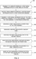
- FIG. 6 illustrates exemplary operations 600 that may be performed, for example, by a control device, such as local controller 140, to control the tong assembly at a work location, in accordance with embodiments of the present disclosure.
- Operations 600 begin at 602, where the control device transmits a first signal representative of a menu of options to a remote interface, such as remote controller 150.
- the menu of options may, for example, represent operation commands for the tong assembly.
- the control device receives from the remote interface a second signal representative of a first operation command.
- the control device transmits a third signal representative of the first operation command to the tong assembly, which causes the tong assembly to operate and rotate the tubulars to make or break a connection.
- the power tong engages a first tubular.
- the backup tong engages a second tubular.
- the sensor system measures a distance between the backup tong and the power tong.
- the control device compares the measured distance to a first threshold value.
- the control device transmits a fifth signal to the tong assembly based on the comparison. If the measured distance is less than the first threshold value, then the tong assembly continues to operate and rotate the tubulars to make or break a connection. If the measured distance is equal to or greater than the first threshold value, then the fifth signal will cause the tong assembly stop operation.
- the fifth signal may be representative of a second operation command.
- Operations 300, 400, 500, and/or 600 may further include one or more of the following steps: comparing the measured and/or monitored distance to a second threshold value; based on the second comparison, stopping rotation of the first threaded tubular relative to the second threaded tubular; disengaging the first threaded tubular from the power tong; disengaging the second threaded tubular from the backup tong; moving the power tong relative to the backup tong; re-engaging the first threaded tubular with the power tong; re-engaging the second threaded tubular with the backup tong; and further rotating the first threaded tubular relative to the second threaded tubular.
- Operations 300, 400, 500, and/or 600 may further include one or more of the following steps: while further rotating the first threaded tubular relative to the second threaded tubular, measuring the distance between the backup tong and the power tong; after stopping rotation, comparing the distance to a second threshold value; based on the second comparison, restarting rotation of the first tubular relative to the second tubular; wherein comparing the distance to a first threshold value further comprises determining whether the distance is within one inch of the first threshold value; and wherein moving the power tong relative to the backup tong further comprises biasing the backup tong towards a neutral position.
- a method of connecting or disconnecting a first tubular to a second tubular includes engaging the first tubular with a power tong; engaging the second tubular with a backup tong; and rotating the first tubular relative to the second tubular.
- the method also includes, while rotating, measuring a distance between the power tong and the backup tong using a sensor, utilizing a controller to monitor a distance between the backup tong and the power tong and comparing the distance to a first threshold value which is a predetermined value; and stopping rotation of the first tubular when the distance equals to the first threshold value.
- the method further includes comparing the distance to a second threshold value.
- the method further comprising based on the comparison, stopping rotation of the first threaded tubular relative to the second threaded tubular.
- the method further including disengaging the first threaded tubular from the power tong; disengaging the second threaded tubular from the backup tong; and moving the power tong relative to the backup tong.
- the method further including re-engaging the first threaded tubular with the power tong; re-engaging the second threaded tubular with the backup tong; and further rotating the first threaded tubular relative to the second threaded tubular.
- the method further comprising while further rotating the first threaded tubular relative to the second threaded tubular, measuring the distance between the backup tong and the power tong.
- a tong assembly comprising: a power tong; a backup tong; a sensor configured to measure a distance between the power tong and the backup tong; and a controller configured to compare the distance to a threshold value.
- the senor is an optical sensor.
- the senor is a cable actuated sensor.
- the method further comprises moving the power tong axially relative to the backup tong while rotating the first threaded tubular relative to the second threaded tubular;and stopping axial movement of the power tong when the distance reaches the first threshold value.
- a method of connecting or disconnecting a first threaded tubular to a second threaded tubular includes engaging the first threaded tubular with a power tong, engaging the second threaded tubular with a backup tong, measuring a distance between the backup tong and the power tong, comparing the distance to a first threshold value, and based on the comparison, rotating the first threaded tubular relative to the second threaded tubular, thereby connecting or disconnecting the tubulars.
- the method further includes, after stopping rotation, comparing the distance to a second threshold value.
- the method further includes stopping axial movement of the power tong when the distance reaches the second threshold value.
- the first threshold value is within a predetermined range of an upper limit of movement of the backup tong relative to the power tong.
- the first threshold value is within a predetermined range of a lower limit of movement of the backup tong relative to the power tong.
- the second threshold value is a remaining distance for connecting or disconnecting the first tubular and the second tubular.
- comparing the distance to a first threshold value further comprises determining whether the distance is within one inch of the first threshold value.
- the method further including disengaging the first threaded tubular from the power tong; disengaging the second threaded tubular from the backup tong; and moving the power tong relative to the backup tong.
- the method further including re-engaging the first threaded tubular with the power tong; re-engaging the second threaded tubular with the backup tong; and further rotating the first threaded tubular relative to the second threaded tubular.
- a tong assembly includes a power tong, a backup tong, a sensor configured to measure a distance between the power tong and the backup tong, and a controller configured to compare the distance to a threshold value.
- moving the power tong relative to the backup tong further comprises biasing the backup tong towards a neutral position.
- the senor is an ultrasonic sensor.
Landscapes
- Engineering & Computer Science (AREA)
- Life Sciences & Earth Sciences (AREA)
- Geology (AREA)
- Mining & Mineral Resources (AREA)
- Physics & Mathematics (AREA)
- Environmental & Geological Engineering (AREA)
- Fluid Mechanics (AREA)
- General Life Sciences & Earth Sciences (AREA)
- Geochemistry & Mineralogy (AREA)
- Mechanical Engineering (AREA)
- Geophysics (AREA)
- Manipulator (AREA)
Claims (12)
- Verfahren zum Verbinden oder Trennen eines ersten und eines zweiten mit Gewinde versehenen Rohrabschnitts, das Folgendes umfasst:In-Eingriff-Bringen des ersten mit Gewinde versehenen Rohrabschnitts mit einer angetriebenen Zange (20);In-Eingriff-Bringen des zweiten mit Gewinde versehenen Rohrabschnitts mit einer Stützzange;Drehen des ersten mit Gewinde versehenen Rohrabschnitts im Verhältnis zu dem zweiten Rohrabschnitt;während des Drehens:Messen eines Abstandes zwischen der angetriebenen Zange (20) und der Stützzange (30) unter Verwendung eines Sensors (210);Benutzen einer Steuerung (250), um den Abstand zwischen der Stützzange (30) und der angetriebenen Zange (20) zu überwachen;Vergleichen des Abstandes mit einem ersten Schwellenwert;Anhalten der Drehung des ersten Rohrabschnitts, wenn der Abstand gleich dem ersten Schwellenwert oder größer als derselbe ist;Vergleichen des Abstandes mit einem zweiten Schwellenwert, wobei der zweite Schwellenwert ein verbleibender Abstand zum Verbinden oder Trennen des ersten mit Gewinde versehenen Rohrabschnitts und des zweiten mit Gewinde versehenen Rohrabschnitts ist; undNeustarten der Drehung des ersten mit Gewinde versehenen Rohrabschnitts im Verhältnis zu dem zweiten Rohrabschnitt, falls der Abstand größer als der zweite Schwellenwert oder gleich demselben ist.
- Verfahren nach Anspruch 1, wobei, auf Grundlage des Vergleichs des Abstandes mit dem zweiten Abstandsschwellenwertes, das Verfahren eines oder mehreres von Folgendem umfasst:Anhalten der Drehung des ersten mit Gewinde versehenen Rohrabschnitts im Verhältnis zu dem zweiten mit Gewinde versehenen Rohrabschnitt;Ausrücken des ersten mit Gewinde versehenen Rohrabschnitts von der angetriebenen Zange (20);Ausrücken des zweiten Rohrabschnitts von der Stützzange (30);Bewegen der angetriebenen Zange (20) im Verhältnis zu der Stützzange (30),Wieder-in-Eingriff-Bringen des ersten mit Gewinde versehenen Rohrabschnitts mit der angetriebenen Zange (20),Wieder-in-Eingriff-Bringen des zweiten mit Gewinde versehenen Rohrabschnitts mit der Stützzange (30); undweiteres Drehen des ersten mit Gewinde versehenen Rohrabschnitts im Verhältnis zu dem zweiten mit Gewinde versehenen Rohrabschnitt.
- Verfahren nach Anspruch 1, wobei der erste Schwellenwert innerhalb eines vorbestimmten Bereichs einer oberen Grenze (230) der Bewegung der angetriebenen Zange (20) im Verhältnis zu der Stützzange (30) liegt.
- Verfahren nach Anspruch 1, wobei der erste Schwellenwert innerhalb eines vorbestimmten Bereichs einer unteren Grenze (240) der Bewegung der angetriebenen Zange (20) im Verhältnis zu der Stützzange (30) liegt.
- Verfahren nach Anspruch 1, wobei das Vergleichen des Abstandes mit dem ersten Schwellenwert ferner das Feststellen umfasst, ob der Abstand innerhalb von 25,4 mm (ein Zoll) des ersten Schwellenwertes liegt.
- Verfahren nach Anspruch 1, das ferner Folgendes umfasst:axiales Bewegen der angetriebenen Zange (20) im Verhältnis zu der Stützzange (30), während der erste mit Gewinde versehene Rohrabschnitt im Verhältnis zu dem zweiten mit Gewinde versehenen Rohrabschnitt gedreht wird; undAnhalten der axialen Bewegung der angetriebenen Zange (20), wenn der Abstand den ersten Schwellenwert erreicht.
- Verfahren nach Anspruch 6, das ferner das Anhalten der axialen Bewegung der angetriebenen Zange (20), wenn der Abstand den zweiten Schwellenwert erreicht, umfasst.
- Verfahren nach Anspruch 7, das ferner Folgendes umfasst:Ausrücken des ersten mit Gewinde versehenen Rohrabschnitts von der angetriebenen Zange (20),Ausrücken des zweiten mit Gewinde versehenen Rohrabschnitts von der Stützzange (30); undBewegen der angetriebenen Zange (20) im Verhältnis zu der Stützzange (30).
- Verfahren nach Anspruch 8, das ferner Folgendes umfasst:Wieder-in-Eingriff-Bringen des ersten mit Gewinde versehenen Rohrabschnitts mit der angetriebenen Zange (20);Wieder-in-Eingriff-Bringen des zweiten mit Gewinde versehenen Rohrabschnitts mit der Stützzange (30); undweiteres Drehen des ersten mit Gewinde versehenen Rohrabschnitts im Verhältnis zu dem zweiten mit Gewinde versehenen Rohrabschnitt.
- Verfahren nach Anspruch 8, wobei das Bewegen der angetriebenen Zange (20) im Verhältnis zu der Stützzange (30) ferner das Vorspannen der Stützzange (30) zu einer neutralen Position hin umfasst.
- Verfahren nach Anspruch 9, das ferner während des weiteren Drehens des ersten mit Gewinde versehenen Rohrabschnitts im Verhältnis zu dem zweiten mit Gewinde versehenen Rohrabschnitt das Messen des Abstandes zwischen der Stützzange (30) und der angetriebenen Zange (20) umfasst.
- Verfahren nach Anspruch 1, wobei der Sensor (210) ein Ultraschallsensor, ein optischer Sensor, eine optische Bildgebungseinrichtung oder ein seilbetätigter Sensor ist.
Applications Claiming Priority (2)
| Application Number | Priority Date | Filing Date | Title |
|---|---|---|---|
| US16/109,414 US10995569B2 (en) | 2018-08-22 | 2018-08-22 | Sensor system for tong assembly |
| PCT/US2019/047323 WO2020041356A1 (en) | 2018-08-22 | 2019-08-20 | Sensor system for tong assembly |
Publications (2)
| Publication Number | Publication Date |
|---|---|
| EP3841276A1 EP3841276A1 (de) | 2021-06-30 |
| EP3841276B1 true EP3841276B1 (de) | 2024-12-18 |
Family
ID=67957379
Family Applications (1)
| Application Number | Title | Priority Date | Filing Date |
|---|---|---|---|
| EP19769274.2A Active EP3841276B1 (de) | 2018-08-22 | 2019-08-20 | Sensorsystem für eine zangenanordnung |
Country Status (4)
| Country | Link |
|---|---|
| US (2) | US10995569B2 (de) |
| EP (1) | EP3841276B1 (de) |
| AU (1) | AU2019324133B2 (de) |
| WO (1) | WO2020041356A1 (de) |
Families Citing this family (5)
| Publication number | Priority date | Publication date | Assignee | Title |
|---|---|---|---|---|
| US11078733B2 (en) | 2018-08-22 | 2021-08-03 | Weatherford Technology Holdings, Llc | Apparatus and methods for determining operational mode of tong assembly |
| US10995569B2 (en) * | 2018-08-22 | 2021-05-04 | Weatherford Technology Holdings, Llc | Sensor system for tong assembly |
| CA3254297A1 (en) | 2020-05-20 | 2025-07-04 | Nabors Drilling Technologies Usa, Inc. | Torque wrench |
| US12320213B2 (en) * | 2023-07-13 | 2025-06-03 | Weatherford Technology Holdings, LLC. | Electronic limit barrier for hydraulic power tongs |
| US20260078646A1 (en) * | 2024-09-18 | 2026-03-19 | Weatherford Technology Holdings, Llc | Tong assembly position adjustment for threaded connection alignment |
Citations (2)
| Publication number | Priority date | Publication date | Assignee | Title |
|---|---|---|---|---|
| US20020077734A1 (en) * | 2000-12-19 | 2002-06-20 | Muller Thomas P. | Hydraulic cylinder life prediction |
| US20050133115A1 (en) * | 2003-12-18 | 2005-06-23 | Gatz Michael C. | Tree harvester |
Family Cites Families (15)
| Publication number | Priority date | Publication date | Assignee | Title |
|---|---|---|---|---|
| NO320735B1 (no) * | 2003-11-25 | 2006-01-23 | V Tech As | Krafttang |
| NO325213B1 (no) | 2004-12-16 | 2008-02-25 | V Tech As | Rorskjotsmoreanordning |
| NO324526B1 (no) | 2005-12-01 | 2007-11-12 | V Tech As | Oppsamlingsanording for borevaeske II |
| US7832470B2 (en) * | 2007-02-27 | 2010-11-16 | Xtech Industries, Inc. | Mouse hole support unit with rotatable or stationary operation |
| US20080307930A1 (en) * | 2007-06-18 | 2008-12-18 | Veverica Jon A | Wrap around tong and method |
| US7717014B2 (en) * | 2007-08-06 | 2010-05-18 | Carstensen Kenneth J | Torque drive for making oil field connections |
| CA2984320C (en) | 2008-11-28 | 2019-09-03 | Key Energy Services, Inc. | Method and system for controlling tongs make-up speed and evaluating and controlling torque at the tongs |
| FI20115922A0 (fi) * | 2011-09-20 | 2011-09-20 | Konecranes Oyj | Nosturin ohjaus |
| US9061868B1 (en) * | 2012-07-19 | 2015-06-23 | Wepco., Inc. | Vacuum-assisted carton or box lifter |
| CA2880452A1 (en) * | 2012-08-08 | 2014-02-13 | National Oilwell Varco, L.P. | Pipe joint apparatus and method |
| KR102225073B1 (ko) * | 2012-10-22 | 2021-03-10 | 퀵실버 드릴링 테크놀로지스, 엘엘씨 | 자동화된 파이프 트립핑 장치 및 방법 |
| US9657539B2 (en) * | 2013-10-01 | 2017-05-23 | Nabors Corporation Services | Automated roughneck |
| US10570677B2 (en) | 2015-06-10 | 2020-02-25 | Warrior Rig Technologies Limited | High efficiency drilling and tripping system |
| CN105545231B (zh) | 2016-02-26 | 2019-08-06 | 山东胜利石油装备产业技术研究院 | 一种浮动式抽油杆自动上卸扣装置 |
| US10995569B2 (en) * | 2018-08-22 | 2021-05-04 | Weatherford Technology Holdings, Llc | Sensor system for tong assembly |
-
2018
- 2018-08-22 US US16/109,414 patent/US10995569B2/en active Active
-
2019
- 2019-08-20 EP EP19769274.2A patent/EP3841276B1/de active Active
- 2019-08-20 WO PCT/US2019/047323 patent/WO2020041356A1/en not_active Ceased
- 2019-08-20 AU AU2019324133A patent/AU2019324133B2/en active Active
-
2021
- 2021-03-02 US US17/189,682 patent/US11525315B2/en active Active
Patent Citations (2)
| Publication number | Priority date | Publication date | Assignee | Title |
|---|---|---|---|---|
| US20020077734A1 (en) * | 2000-12-19 | 2002-06-20 | Muller Thomas P. | Hydraulic cylinder life prediction |
| US20050133115A1 (en) * | 2003-12-18 | 2005-06-23 | Gatz Michael C. | Tree harvester |
Also Published As
| Publication number | Publication date |
|---|---|
| AU2019324133A1 (en) | 2021-03-04 |
| US20210180416A1 (en) | 2021-06-17 |
| US20200063506A1 (en) | 2020-02-27 |
| US10995569B2 (en) | 2021-05-04 |
| EP3841276A1 (de) | 2021-06-30 |
| WO2020041356A1 (en) | 2020-02-27 |
| AU2019324133B2 (en) | 2024-10-10 |
| US11525315B2 (en) | 2022-12-13 |
Similar Documents
| Publication | Publication Date | Title |
|---|---|---|
| EP3841276B1 (de) | Sensorsystem für eine zangenanordnung | |
| US10366507B2 (en) | Optical imaging and assessment system for tong cassette positioning device | |
| US11486210B2 (en) | Apparatus and methods for determining operational mode of tong assembly | |
| CA3019308A1 (en) | Pipe tally vision system | |
| US11162310B2 (en) | Autonomous connection makeup and evaluation | |
| WO2020102089A1 (en) | Optical tool joint assist for iron roughneck | |
| US8065937B2 (en) | Method and device for positioning a power tong at a pipe joint | |
| WO2020176485A1 (en) | Tool joint assist for iron roughneck | |
| US11060381B2 (en) | Tong cassette positioning device | |
| CN220366869U (zh) | 一种用于钻修井作业中接箍的视觉检测装置 | |
| CN212989936U (zh) | 一种基于激光扫描传感器的钻杆对接检测控制系统 | |
| CN109296331B (zh) | 一种水下生产控制系统自动对中安装系统 | |
| WO2025113026A1 (zh) | 可视化修井作业方法及作业装置 | |
| CN121184065A (zh) | 一种基于视觉识别的连续管井口自动对中作业控制方法 |
Legal Events
| Date | Code | Title | Description |
|---|---|---|---|
| STAA | Information on the status of an ep patent application or granted ep patent |
Free format text: STATUS: UNKNOWN |
|
| STAA | Information on the status of an ep patent application or granted ep patent |
Free format text: STATUS: THE INTERNATIONAL PUBLICATION HAS BEEN MADE |
|
| PUAI | Public reference made under article 153(3) epc to a published international application that has entered the european phase |
Free format text: ORIGINAL CODE: 0009012 |
|
| STAA | Information on the status of an ep patent application or granted ep patent |
Free format text: STATUS: REQUEST FOR EXAMINATION WAS MADE |
|
| 17P | Request for examination filed |
Effective date: 20210209 |
|
| AK | Designated contracting states |
Kind code of ref document: A1 Designated state(s): AL AT BE BG CH CY CZ DE DK EE ES FI FR GB GR HR HU IE IS IT LI LT LU LV MC MK MT NL NO PL PT RO RS SE SI SK SM TR |
|
| DAV | Request for validation of the european patent (deleted) | ||
| DAX | Request for extension of the european patent (deleted) | ||
| STAA | Information on the status of an ep patent application or granted ep patent |
Free format text: STATUS: EXAMINATION IS IN PROGRESS |
|
| 17Q | First examination report despatched |
Effective date: 20230913 |
|
| P01 | Opt-out of the competence of the unified patent court (upc) registered |
Effective date: 20230922 |
|
| GRAP | Despatch of communication of intention to grant a patent |
Free format text: ORIGINAL CODE: EPIDOSNIGR1 |
|
| STAA | Information on the status of an ep patent application or granted ep patent |
Free format text: STATUS: GRANT OF PATENT IS INTENDED |
|
| INTG | Intention to grant announced |
Effective date: 20240422 |
|
| GRAJ | Information related to disapproval of communication of intention to grant by the applicant or resumption of examination proceedings by the epo deleted |
Free format text: ORIGINAL CODE: EPIDOSDIGR1 |
|
| STAA | Information on the status of an ep patent application or granted ep patent |
Free format text: STATUS: EXAMINATION IS IN PROGRESS |
|
| GRAP | Despatch of communication of intention to grant a patent |
Free format text: ORIGINAL CODE: EPIDOSNIGR1 |
|
| STAA | Information on the status of an ep patent application or granted ep patent |
Free format text: STATUS: GRANT OF PATENT IS INTENDED |
|
| INTC | Intention to grant announced (deleted) | ||
| INTG | Intention to grant announced |
Effective date: 20240912 |
|
| GRAS | Grant fee paid |
Free format text: ORIGINAL CODE: EPIDOSNIGR3 |
|
| GRAA | (expected) grant |
Free format text: ORIGINAL CODE: 0009210 |
|
| STAA | Information on the status of an ep patent application or granted ep patent |
Free format text: STATUS: THE PATENT HAS BEEN GRANTED |
|
| AK | Designated contracting states |
Kind code of ref document: B1 Designated state(s): AL AT BE BG CH CY CZ DE DK EE ES FI FR GB GR HR HU IE IS IT LI LT LU LV MC MK MT NL NO PL PT RO RS SE SI SK SM TR |
|
| REG | Reference to a national code |
Ref country code: CH Ref legal event code: EP |
|
| REG | Reference to a national code |
Ref country code: DE Ref legal event code: R096 Ref document number: 602019063695 Country of ref document: DE |
|
| REG | Reference to a national code |
Ref country code: IE Ref legal event code: FG4D |
|
| REG | Reference to a national code |
Ref country code: LT Ref legal event code: MG9D |
|
| PG25 | Lapsed in a contracting state [announced via postgrant information from national office to epo] |
Ref country code: HR Free format text: LAPSE BECAUSE OF FAILURE TO SUBMIT A TRANSLATION OF THE DESCRIPTION OR TO PAY THE FEE WITHIN THE PRESCRIBED TIME-LIMIT Effective date: 20241218 |
|
| PG25 | Lapsed in a contracting state [announced via postgrant information from national office to epo] |
Ref country code: FI Free format text: LAPSE BECAUSE OF FAILURE TO SUBMIT A TRANSLATION OF THE DESCRIPTION OR TO PAY THE FEE WITHIN THE PRESCRIBED TIME-LIMIT Effective date: 20241218 |
|
| PG25 | Lapsed in a contracting state [announced via postgrant information from national office to epo] |
Ref country code: BG Free format text: LAPSE BECAUSE OF FAILURE TO SUBMIT A TRANSLATION OF THE DESCRIPTION OR TO PAY THE FEE WITHIN THE PRESCRIBED TIME-LIMIT Effective date: 20241218 |
|
| REG | Reference to a national code |
Ref country code: NL Ref legal event code: MP Effective date: 20241218 |
|
| PG25 | Lapsed in a contracting state [announced via postgrant information from national office to epo] |
Ref country code: LV Free format text: LAPSE BECAUSE OF FAILURE TO SUBMIT A TRANSLATION OF THE DESCRIPTION OR TO PAY THE FEE WITHIN THE PRESCRIBED TIME-LIMIT Effective date: 20241218 Ref country code: GR Free format text: LAPSE BECAUSE OF FAILURE TO SUBMIT A TRANSLATION OF THE DESCRIPTION OR TO PAY THE FEE WITHIN THE PRESCRIBED TIME-LIMIT Effective date: 20250319 |
|
| PG25 | Lapsed in a contracting state [announced via postgrant information from national office to epo] |
Ref country code: RS Free format text: LAPSE BECAUSE OF FAILURE TO SUBMIT A TRANSLATION OF THE DESCRIPTION OR TO PAY THE FEE WITHIN THE PRESCRIBED TIME-LIMIT Effective date: 20250318 |
|
| PG25 | Lapsed in a contracting state [announced via postgrant information from national office to epo] |
Ref country code: NL Free format text: LAPSE BECAUSE OF FAILURE TO SUBMIT A TRANSLATION OF THE DESCRIPTION OR TO PAY THE FEE WITHIN THE PRESCRIBED TIME-LIMIT Effective date: 20241218 |
|
| REG | Reference to a national code |
Ref country code: AT Ref legal event code: MK05 Ref document number: 1752368 Country of ref document: AT Kind code of ref document: T Effective date: 20241218 |
|
| PG25 | Lapsed in a contracting state [announced via postgrant information from national office to epo] |
Ref country code: SM Free format text: LAPSE BECAUSE OF FAILURE TO SUBMIT A TRANSLATION OF THE DESCRIPTION OR TO PAY THE FEE WITHIN THE PRESCRIBED TIME-LIMIT Effective date: 20241218 |
|
| PG25 | Lapsed in a contracting state [announced via postgrant information from national office to epo] |
Ref country code: PL Free format text: LAPSE BECAUSE OF FAILURE TO SUBMIT A TRANSLATION OF THE DESCRIPTION OR TO PAY THE FEE WITHIN THE PRESCRIBED TIME-LIMIT Effective date: 20241218 |
|
| PG25 | Lapsed in a contracting state [announced via postgrant information from national office to epo] |
Ref country code: ES Free format text: LAPSE BECAUSE OF FAILURE TO SUBMIT A TRANSLATION OF THE DESCRIPTION OR TO PAY THE FEE WITHIN THE PRESCRIBED TIME-LIMIT Effective date: 20241218 |
|
| PGFP | Annual fee paid to national office [announced via postgrant information from national office to epo] |
Ref country code: GB Payment date: 20250626 Year of fee payment: 7 |
|
| PG25 | Lapsed in a contracting state [announced via postgrant information from national office to epo] |
Ref country code: IS Free format text: LAPSE BECAUSE OF FAILURE TO SUBMIT A TRANSLATION OF THE DESCRIPTION OR TO PAY THE FEE WITHIN THE PRESCRIBED TIME-LIMIT Effective date: 20250418 |
|
| PG25 | Lapsed in a contracting state [announced via postgrant information from national office to epo] |
Ref country code: PT Free format text: LAPSE BECAUSE OF FAILURE TO SUBMIT A TRANSLATION OF THE DESCRIPTION OR TO PAY THE FEE WITHIN THE PRESCRIBED TIME-LIMIT Effective date: 20250421 |
|
| PG25 | Lapsed in a contracting state [announced via postgrant information from national office to epo] |
Ref country code: EE Free format text: LAPSE BECAUSE OF FAILURE TO SUBMIT A TRANSLATION OF THE DESCRIPTION OR TO PAY THE FEE WITHIN THE PRESCRIBED TIME-LIMIT Effective date: 20241218 |
|
| PG25 | Lapsed in a contracting state [announced via postgrant information from national office to epo] |
Ref country code: AT Free format text: LAPSE BECAUSE OF FAILURE TO SUBMIT A TRANSLATION OF THE DESCRIPTION OR TO PAY THE FEE WITHIN THE PRESCRIBED TIME-LIMIT Effective date: 20241218 Ref country code: RO Free format text: LAPSE BECAUSE OF FAILURE TO SUBMIT A TRANSLATION OF THE DESCRIPTION OR TO PAY THE FEE WITHIN THE PRESCRIBED TIME-LIMIT Effective date: 20241218 |
|
| PG25 | Lapsed in a contracting state [announced via postgrant information from national office to epo] |
Ref country code: SK Free format text: LAPSE BECAUSE OF FAILURE TO SUBMIT A TRANSLATION OF THE DESCRIPTION OR TO PAY THE FEE WITHIN THE PRESCRIBED TIME-LIMIT Effective date: 20241218 |
|
| PG25 | Lapsed in a contracting state [announced via postgrant information from national office to epo] |
Ref country code: CZ Free format text: LAPSE BECAUSE OF FAILURE TO SUBMIT A TRANSLATION OF THE DESCRIPTION OR TO PAY THE FEE WITHIN THE PRESCRIBED TIME-LIMIT Effective date: 20241218 |
|
| PG25 | Lapsed in a contracting state [announced via postgrant information from national office to epo] |
Ref country code: IT Free format text: LAPSE BECAUSE OF FAILURE TO SUBMIT A TRANSLATION OF THE DESCRIPTION OR TO PAY THE FEE WITHIN THE PRESCRIBED TIME-LIMIT Effective date: 20241218 |
|
| PG25 | Lapsed in a contracting state [announced via postgrant information from national office to epo] |
Ref country code: SE Free format text: LAPSE BECAUSE OF FAILURE TO SUBMIT A TRANSLATION OF THE DESCRIPTION OR TO PAY THE FEE WITHIN THE PRESCRIBED TIME-LIMIT Effective date: 20241218 |
|
| REG | Reference to a national code |
Ref country code: DE Ref legal event code: R097 Ref document number: 602019063695 Country of ref document: DE |
|
| PG25 | Lapsed in a contracting state [announced via postgrant information from national office to epo] |
Ref country code: DK Free format text: LAPSE BECAUSE OF FAILURE TO SUBMIT A TRANSLATION OF THE DESCRIPTION OR TO PAY THE FEE WITHIN THE PRESCRIBED TIME-LIMIT Effective date: 20241218 |
|
| PGFP | Annual fee paid to national office [announced via postgrant information from national office to epo] |
Ref country code: DE Payment date: 20250624 Year of fee payment: 7 |
|
| PGFP | Annual fee paid to national office [announced via postgrant information from national office to epo] |
Ref country code: NO Payment date: 20250808 Year of fee payment: 7 |
|
| PLBE | No opposition filed within time limit |
Free format text: ORIGINAL CODE: 0009261 |
|
| STAA | Information on the status of an ep patent application or granted ep patent |
Free format text: STATUS: NO OPPOSITION FILED WITHIN TIME LIMIT |
|
| REG | Reference to a national code |
Ref country code: CH Ref legal event code: L10 Free format text: ST27 STATUS EVENT CODE: U-0-0-L10-L00 (AS PROVIDED BY THE NATIONAL OFFICE) Effective date: 20251029 |
|
| 26N | No opposition filed |
Effective date: 20250919 |
|
| REG | Reference to a national code |
Ref country code: CH Ref legal event code: H13 Free format text: ST27 STATUS EVENT CODE: U-0-0-H10-H13 (AS PROVIDED BY THE NATIONAL OFFICE) Effective date: 20260324 |
|
| PG25 | Lapsed in a contracting state [announced via postgrant information from national office to epo] |
Ref country code: MC Free format text: LAPSE BECAUSE OF FAILURE TO SUBMIT A TRANSLATION OF THE DESCRIPTION OR TO PAY THE FEE WITHIN THE PRESCRIBED TIME-LIMIT Effective date: 20241218 |
|
| PG25 | Lapsed in a contracting state [announced via postgrant information from national office to epo] |
Ref country code: LU Free format text: LAPSE BECAUSE OF NON-PAYMENT OF DUE FEES Effective date: 20250820 |
|
| PG25 | Lapsed in a contracting state [announced via postgrant information from national office to epo] |
Ref country code: CH Free format text: LAPSE BECAUSE OF NON-PAYMENT OF DUE FEES Effective date: 20250831 |