EP3841308B1 - Vorrichtung und verfahren zur montage einer dynamischen dichtung in einem eine drehwelle aufnehmenden lager - Google Patents
Vorrichtung und verfahren zur montage einer dynamischen dichtung in einem eine drehwelle aufnehmenden lager Download PDFInfo
- Publication number
- EP3841308B1 EP3841308B1 EP19753157.7A EP19753157A EP3841308B1 EP 3841308 B1 EP3841308 B1 EP 3841308B1 EP 19753157 A EP19753157 A EP 19753157A EP 3841308 B1 EP3841308 B1 EP 3841308B1
- Authority
- EP
- European Patent Office
- Prior art keywords
- housing
- seal
- washer
- rotating shaft
- axial
- Prior art date
- Legal status (The legal status is an assumption and is not a legal conclusion. Google has not performed a legal analysis and makes no representation as to the accuracy of the status listed.)
- Active
Links
Images
Classifications
-
- F—MECHANICAL ENGINEERING; LIGHTING; HEATING; WEAPONS; BLASTING
- F16—ENGINEERING ELEMENTS AND UNITS; GENERAL MEASURES FOR PRODUCING AND MAINTAINING EFFECTIVE FUNCTIONING OF MACHINES OR INSTALLATIONS; THERMAL INSULATION IN GENERAL
- F16C—SHAFTS; FLEXIBLE SHAFTS; ELEMENTS OR CRANKSHAFT MECHANISMS; ROTARY BODIES OTHER THAN GEARING ELEMENTS; BEARINGS
- F16C33/00—Parts of bearings; Special methods for making bearings or parts thereof
- F16C33/72—Sealings
- F16C33/76—Sealings of ball or roller bearings
- F16C33/78—Sealings of ball or roller bearings with a diaphragm, disc, or ring, with or without resilient members
- F16C33/7886—Sealings of ball or roller bearings with a diaphragm, disc, or ring, with or without resilient members mounted outside the gap between the inner and outer races, e.g. sealing rings mounted to an end face or outer surface of a race
-
- F—MECHANICAL ENGINEERING; LIGHTING; HEATING; WEAPONS; BLASTING
- F16—ENGINEERING ELEMENTS AND UNITS; GENERAL MEASURES FOR PRODUCING AND MAINTAINING EFFECTIVE FUNCTIONING OF MACHINES OR INSTALLATIONS; THERMAL INSULATION IN GENERAL
- F16J—PISTONS; CYLINDERS; SEALINGS
- F16J15/00—Sealings
- F16J15/16—Sealings between relatively-moving surfaces
- F16J15/32—Sealings between relatively-moving surfaces with elastic sealings, e.g. O-rings
- F16J15/3204—Sealings between relatively-moving surfaces with elastic sealings, e.g. O-rings with at least one lip
- F16J15/3216—Sealings between relatively-moving surfaces with elastic sealings, e.g. O-rings with at least one lip supported in a direction parallel to the surfaces
Definitions
- the invention relates to the methods of installing a dynamic seal inside a casing receiving a rotating shaft. More specifically, the invention relates to the methods of axial positioning of the seal inside the casing, in radial interposition between the casing and the rotating shaft. By way of indication, one application of the invention relates to the seal between a drive shaft of a drive machine and a housing of a variable speed gearbox.
- a rotating shaft extends axially through at least one bearing provided inside a housing.
- the bearing houses at least one rolling member axially traversed by the rotating shaft, and the casing houses at least one dynamic seal to provide sealing between the casing and the external environment.
- the seal is then axially positioned inside the casing in radial interposition between the casing and the rotating shaft.
- the current case is considered in which the rotating shaft passes through a bearing which is formed at the inlet of the housing in the direction of axial insertion of the rotating shaft from the outside inwards. of the case.
- the shaft is then introduced through an inlet opening of the housing, which is arranged upstream of the rolling member in the direction of introduction of the shaft inside the bearing.
- At least one lip seal(s) is interposed radially between the casing and the rotating shaft while being axially disposed between the opening and the running gear.
- the seal thus forms an obstacle, on the one hand, to the introduction of particles from the exterior towards the interior of the casing and, on the other hand, to an escape of lubricant from the casing.
- the seal is subject to wear as a result of its friction against the rotating shaft, which requires its replacement to prevent leakage of lubricant from the housing.
- the axial positioning of the replacement seal can be tricky to achieve aftermarket. Indeed, it is common for an initial seal installed as original equipment inside the case to be produced in the factory using specific tools, which are calibrated to position the seal rigorously. initial inside the housing in a predefined axial position between the opening and the running gear. During an operation to replace the initial seal after wear, the operator may not have said specific tooling, which is expensive, to install a replacement seal after installation inside the housing. The axial positioning of the replacement seal by the operator is then carried out by guesswork, at the risk of affecting its correct axial positioning inside the housing.
- a common solution is to form a heel in the housing providing a shoulder for axial positioning of the seal. This allows an operator who does not have said specific tool to retrofit the replacement seal in the correct axial position, by pushing it through the inlet opening of the bearing until it is applied in axial support against the heel.
- a solution may not be applicable, in particular because of the axial bulk induced by the formation of the heel inside the housing and/or by a predefined axial gap between the seal and the running gear to prevent their friction against each other.
- Such a situation arises in particular when the size of the housing must be reduced at best, such as for example for a housing of a gearbox fitted to a motor vehicle which is commonly installed in a cluttered environment.
- a peripheral wear groove in the rotating shaft may form as a result of the friction of the seal.
- the result is a risk of lubricant escaping from the housing via said groove, despite the installation as aftermarket of a replacement seal in the correct axial position inside the housing.
- the subject of the present invention is a device comprising a housing for receiving a rotating shaft and a dynamic joint, and facilitating the axial positioning of the dynamic seal inside the housing.
- the invention also relates to a method for mounting a dynamic seal inside said device.
- An object of the invention is to propose a solution providing rigorous axial positioning of the dynamic seal inside the housing, whether it is an initial seal installed as original equipment inside the housing or a replacement seal installed in second mounts inside the case.
- Another object of the invention is to propose such a solution that can be implemented at lower cost, both structurally and with regard to the installation as aftermarket of a replacement seal inside the housing, after wear. an initial seal installed as original equipment inside the case using specific tools. It is in particular aimed at the search for a solution which is economically viable and even advantageous, allowing in particular its application in the automotive field subject to notoriously severe economic competition.
- Another object of the invention is to propose such a solution which avoids a significant increase in the axial extension of a said box, the axial size of which is predefined.
- the aim is in particular not to modify the axial extension of the housing or its architecture, to allow its installation in an imposed environment, such as in particular on a motor vehicle having a predefined restrictive architecture.
- Another object of the invention is to perfect the tightness obtained by fitting a said seal, whether it is an initial seal installed inside the case as original equipment or a replacement seal installed inside aftermarket housing after initial seal wear.
- the invention is recognizable in that said seal is at an axial distance upstream of the washer along a direction of insertion of the rotating shaft through the opening towards the inside of the bearing, and the washer is axially interposed in contact between the rolling member and a heel provided by the housing.
- the washer is permanently installed inside the housing, being then used to form a stop for a replacement seal installed as aftermarket inside the housing, during a maintenance operation aimed at replacing an initial seal worn installed inside the box as original equipment.
- the washer is preferably made of steel, presenting with regard to its diameter a small axial thickness, indicatively between 1 mm (one millimeter) and 3 mm.
- the washer is made from a material different from that of the casing providing the bearing, such as aluminum which is reputed to be light, in order to be integrated in particular into a variable-speed gearbox of a motor vehicle, the mass of which is sought to be the lowest. possible.
- the axial positioning of the replacement seal inside the housing via the washer makes it possible to maintain the same axial dimensioning of the housing to make it compatible with an imposed dimensional constraint of the housing, such as for example for its location on a predefined basis of a motor vehicle model.
- the washer interfaced between the rolling member and the seal protects the seal from dynamic contact with the rolling member, such as in particular a rubbing contact against a rotating ring of the rolling member secured to the rotating shaft.
- the seal can be rigorously placed in an axial position inside the housing without having to use specific tools used to mount the initial seal inside the housing, in particular by axial thrust exerted by an operator against the seal through the opening the case.
- the heel in particular provides an axial bearing member for the rolling member in a direction opposite to the direction of insertion of the rotating shaft inside the housing.
- the heel is arranged upstream of the washer and downstream of an axial reception tunnel for the seal inside the housing.
- the rolling member bears axially against the heel via the washer, in a direction opposite to the direction of insertion of the rotating shaft through the opening towards the inside of the housing.
- the seal is housed inside a tunnel made in the casing.
- the diameter of the internal recess of the washer is less than the diameter of the tunnel, a diametrical extension of said shoulder being delimited between the internal recess of the washer and a wall of the casing providing the tunnel.
- Said at least one dynamic seal is preferably an elastomer seal provided with at least one lip, potentially including a PTFE lip (from the acronym of PolyTetraFluoroEthylene), bearing radially against the rotating shaft.
- a PTFE lip from the acronym of PolyTetraFluoroEthylene
- Such a PTFE lip has the advantage of being more robust than the flexible elastomer lips which are commonly used to produce a seal and which are made from a softer material than PTFE.
- the invention also relates to a method of mounting according to claim 5 of at least one dynamic seal inside a device as previously described.
- the method is recognizable in that the dynamic seal is axially introduced by an operator through the opening towards the inside of the housing, being axially pushed by the operator until it takes axial support. against the shoulder created by the puck.
- the method is implemented to install as aftermarket a replacement seal inside the case, in particular in a maintenance workshop, to replace a worn initial seal installed as original equipment inside the case at an axial distance of the washer.
- This allows installation as original equipment of the initial seal by means of specific tooling configured as a member for axial positioning of the initial seal inside the housing, without having to apply the initial gasket against the washer, permanently installed in the casing and whose use is reserved for the replacement gasket.
- the sealing provided by the replacement seal installed inside the housing as an aftermarket is obtained reliably, including in the event of any peripheral wear of the rotating shaft caused by the radial bearing of the initial seal against the rotating shaft, mounted inside the housing at an axial distance from the washer.
- the dynamic seal mounted in axial application against said shoulder is a replacement seal installed as aftermarket inside the housing, replacing an initial seal installed as original equipment inside the housing axial distance of the washer, upstream of the washer following the direction of insertion of the rotating shaft through the opening towards the inside of the housing.
- the axial separation distance between the initial seal and the washer is between 0.5 mm and 20 mm.
- the invention also relates to a gearbox housing a driven shaft and a device as described above in which the bearing receives a motor shaft from outside the housing, said rotating shaft being a constituent of said motor shaft.
- the motor shaft is in particular part of a driving machine and is dedicated to driving at least one driven shaft housed inside the variable speed gearbox.
- the invention also relates to a motor vehicle equipped with at least one propulsion engine of the vehicle which is provided with a motor shaft for driving a receiving shaft housed inside a variable speed gearbox fitted to the vehicle which conforms to the variable speed gearbox of the invention.
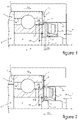
- FIG. 1 An exemplary embodiment of the invention will be described in relation to the figures of the appended plate, in which the figure 1 and the figure 2 are illustrations in axial half-section of the same device comprising a dynamic seal and a housing providing a bearing for receiving a rotating shaft, according to an embodiment of the invention.
- the seal is an initial seal installed as original equipment inside the case and on the figure 2 the seal is a replacement seal installed as an aftermarket fit inside the housing to replace the initial seal after it has worn out.
- a housing 1 provides a bearing 2 for receiving a rotating shaft 3 of axial extension A1.
- the rotating shaft 3 is introduced from the exterior of the casing 1 towards the interior of the bearing 2 through an opening 4 which the casing 1 comprises.
- the bearing 2 comprises a rolling member 5 through which the rotating shaft 3 passes, such a ball bearing in the example shown, being placed in axial support against a heel 6 formed inside the housing 1.
- the rolling member 5 is axially applied against the heel 6 in an axially opposite direction S2 in the direction S1 of introduction of the rotating shaft 3 inside the casing 1.
- the housing 1 selectively houses identical dynamic seals 7a, 7b, to prevent the escape of lubricant from the housing 1 and/or the introduction of particles from the exterior to the interior of the housing 1.
- one or the other of the seals 7a, 7b is diametrically housed inside an axial tunnel 8 formed inside the housing 1 and comprises a lip 9 placed in radial support against the periphery of the rotating shaft 3.
- One or the other of the seals 7a, 7b is axially arranged in interposition between the opening 4 and the running gear 5.
- an initial seal 7a is installed as original equipment inside the housing 1 during the development of the housing 1 in the production workshop. It is common that in the production workshop, specific tools are used to facilitate the mounting of the initial gasket 7a inside the casing 1, in particular on a potentially automated production and/or fitting line for the casing 1 . Such type of tooling makes it possible to install the initial seal 7a inside the housing 1 in an axial position predefined by the tooling, at an axial distance from the running gear 5.
- the heel 6 against which the rolling member 5 bears axially to receive a member for axial positioning of the replacement seal 7b Said positioning member is formed of a washer 11 which is axially interposed in contact between on the one hand an outer ring 5a of the rolling member 5 fixedly mounted inside the housing 1, and on the other hand the heel 6 of axial support of the rolling member 5 via said fixed ring 5a.
- the replacement seal 7b is applied against the washer 11 during its assembly inside the housing 1, avoiding any contact with the running gear 5.
- the device comprises said opening 4 for introducing the rotating shaft 3 through it, then the joint 7a initial or the replacement seal 7b, then the washer 11 centered at its periphery inside a housing 12 for receiving the rolling member 5, then the rolling member 5 bearing axially against the heel 6 via washer 11.
- the diameter D1 of the interior recess 13 of the washer 11 is less than the diameter D2 of the tunnel 8 receiving the initial seal 7a or the replacement seal 7b.
- the washer 11 thus provides a shoulder 14 against which the replacement seal 7b bears axially for its axial positioning inside the housing 1, as illustrated in the figure 2 .
- the diametral extension D3 of the shoulder 14 is delimited between the interior recess 13 of the washer 11 and the wall 2a of the casing 1 delimiting the tunnel 8.
- the initial seal 7a is placed at an axial distance D4 from the washer 11, indicatively between 0.5 mm and 20 mm.
- the replacement seal 7b being identical to the initial seal 7a and being positioned inside the housing 1 in axial support against the shoulder 14 provided by the washer 11, a possible groove 10 engraved on the periphery of the rotating shaft 3 by the initial seal 7a does not affect the quality of the seal obtained via the replacement seal 7b.
Landscapes
- Engineering & Computer Science (AREA)
- General Engineering & Computer Science (AREA)
- Mechanical Engineering (AREA)
- Sealing Of Bearings (AREA)
- Rolling Contact Bearings (AREA)
- Sealing With Elastic Sealing Lips (AREA)
Claims (8)
- Vorrichtung umfassend :- ein Gehäuse (1), das ein Lager (2) zur Aufnahme einer rotierenden Welle (3) bereitstellt, wobei dieses Lager (2) ein Wälzelement (5) umfasst, wobei dieses Gehäuse eine Öffnung (4) zur axialen Einführung (A1) der rotierenden Welle (3) durch sie hindurch in Richtung des Wälzkörpers (5)- mindestens eine dynamische Dichtung (7a), die axial innerhalb des Gehäuses (1) angeordnet ist, wobeidas Gehäuse (1) eine Unterlegscheibe (11) axial (A1), die zwischen der Öffnung (4) und dem Wälzkörper (5) angeordnet ist, wobei die Unterlegscheibe (11) eine Schulter (14) bereitstellt, gegen die die Dichtung (7a) geeignet ist, eine axiale (A1) Abstützung für ihre axiale Positionierung (A1) zu übernehmen. innerhalb des Gehäuses (1), um die Abdichtung des Lagers (2) sicherzustellen, dadurch gekennzeichnet, dass die Dichtung (7a) in einem axialen Abstand (D4) stromaufwärts von der Unterlegscheibe (11) in einer Einführrichtung (S1) angeordnet ist die rotierende Welle (3) durch die Öffnung (4) zur Innenseite des Lagers (2) führt und die Unterlegscheibe (11) axial (A1) bei eingefügt ist Kontakt zwischen dem Fahrwerk (5) und einem vom Gehäuse (1) bereitgestellten Absatz (6).
- - Vorrichtung nach Anspruch 1, dadurch gekennzeichnet, dass das Rollelement (5) axial (A1) gegen den Absatz (6) über die Unterlegscheibe (11) anliegt, in einer Richtung (S2) entgegengesetzt zu der Richtung (S1) für Einführen der rotierenden Welle (3) durch die Öffnung (4) zum Inneren des Gehäuses (1).
- - Vorrichtung nach einem der Ansprüche 1 bis 2, dadurch gekennzeichnet, dass die Dichtung (7a) in einem im Gehäuse (1) ausgebildeten Tunnel (8) untergebracht ist, dessen Durchmesser (D1) der inneren Aussparung (13) entspricht der Unterlegscheibe (11) kleiner ist als der Durchmesser (D2) des Tunnels (8), wobei eine diametrale Verlängerung (D3) der Schulter (14) zwischen der inneren Aussparung (13) der Unterlegscheibe (11) und begrenzt ist eine Wand (2a) des Gehäuses (1), die den Tunnel (8) bildet.
- - Vorrichtung nach einem der Ansprüche 1 bis 3, dadurch gekennzeichnet, dass die mindestens eine dynamische Dichtung (7a, 7b) eine Elastomerdichtung ist, die mit mindestens einer Lippe versehen ist, die mindestens eine PTFE-Lippe (9) trägt radial gegen die rotierende Welle (3).
- - Verfahren zum Montieren mindestens eines dynamischen Gelenks (7a, 7b) innerhalb einer Vorrichtung nach einem der Ansprüche 1 bis 4, dadurch gekennzeichnet, dass das dynamische Gelenk (7b) axial (A1) von einem Bediener durch das eingeführt wird Öffnung (4) in Richtung der Innenseite des Gehäuses (1), axial von der Bedienungsperson gedrückt, bis sie eine axiale Abstützung gegen die von der Unterlegscheibe (11) gebildete Schulter (14) erhält, gegen die diese dynamische Dichtung (7b) in axialer Anlage angebracht ist wobei die Schulter (14) eine Ersatzdichtung (7b) ist, die als Nachrüstsatz innerhalb des Gehäuses (1) installiert wird und eine ursprünglich als Originalausrüstung innerhalb des Gehäuses (1) in einem axialen Abstand von der Unterlegscheibe (11) installierte Dichtung (7a) ersetzt, stromaufwärts der Unterlegscheibe (11) in Richtung (S1) der Einführung der rotierenden Welle (3) durch die Öffnung (4) in das Innere des Gehäuses (1).
- -Verfahren nach Anspruch 5, dadurch gekennzeichnet, dass der axiale Trennabstand zwischen der Dichtung (7a) und der Unterlegscheibe (11) zwischen 0,5 mm und 20 mm liegt.
- - Getriebe, das eine angetriebene Welle und eine Vorrichtung nach einem der Ansprüche 1 bis 4 aufnimmt, wobei das Lager (2) eine Motorwelle von außerhalb des Gehäuses (1) aufnimmt, wobei die Drehwelle (3) die Motorwelle bildet.
- - Kraftfahrzeug, das mit mindestens einem Antriebsmotor des Fahrzeugs ausgestattet ist, der mit einer Antriebsmotorwelle einer Aufnahmewelle versehen ist, die in einem am Fahrzeug angebrachten Getriebe mit variabler Geschwindigkeit untergebracht ist, dadurch gekennzeichnet, dass das Getriebe mit variabler Geschwindigkeit dem Anspruch entspricht 7.
Applications Claiming Priority (2)
| Application Number | Priority Date | Filing Date | Title |
|---|---|---|---|
| FR1857645A FR3085193B1 (fr) | 2018-08-24 | 2018-08-24 | Dispositif et procede de montage d'un joint dynamique a l'interieur d'un palier recevant un arbre tournant |
| PCT/FR2019/051717 WO2020039131A1 (fr) | 2018-08-24 | 2019-07-09 | Dispositif et procédé de montage d'un joint dynamique à l'intérieur d'un palier recevant un arbre tournant |
Publications (2)
| Publication Number | Publication Date |
|---|---|
| EP3841308A1 EP3841308A1 (de) | 2021-06-30 |
| EP3841308B1 true EP3841308B1 (de) | 2022-11-09 |
Family
ID=63684170
Family Applications (1)
| Application Number | Title | Priority Date | Filing Date |
|---|---|---|---|
| EP19753157.7A Active EP3841308B1 (de) | 2018-08-24 | 2019-07-09 | Vorrichtung und verfahren zur montage einer dynamischen dichtung in einem eine drehwelle aufnehmenden lager |
Country Status (3)
| Country | Link |
|---|---|
| EP (1) | EP3841308B1 (de) |
| FR (1) | FR3085193B1 (de) |
| WO (1) | WO2020039131A1 (de) |
Family Cites Families (6)
| Publication number | Priority date | Publication date | Assignee | Title |
|---|---|---|---|---|
| BE494855A (de) * | 1950-03-30 | 1950-07-17 | ||
| US6503168B2 (en) * | 2001-06-12 | 2003-01-07 | Apex Dynamics, Inc. | Planetary gear device for reducing speed of an output shaft of a motor |
| JP5404300B2 (ja) * | 2009-10-16 | 2014-01-29 | 株式会社ツバキエマソン | 直線作動機 |
| JP5475867B2 (ja) * | 2010-03-08 | 2014-04-16 | 本田技研工業株式会社 | 自動車用トランスミッションオイルシール |
| CN101839346B (zh) * | 2010-04-19 | 2012-01-25 | 沃德(天津)传动有限公司 | 一种油封调节装置及设有该调节装置的减速机 |
| FR3021887A1 (fr) * | 2014-06-05 | 2015-12-11 | Peugeot Citroen Automobiles Sa | Procede et dispositif de montage d'un joint circulaire |
-
2018
- 2018-08-24 FR FR1857645A patent/FR3085193B1/fr not_active Expired - Fee Related
-
2019
- 2019-07-09 WO PCT/FR2019/051717 patent/WO2020039131A1/fr not_active Ceased
- 2019-07-09 EP EP19753157.7A patent/EP3841308B1/de active Active
Also Published As
| Publication number | Publication date |
|---|---|
| EP3841308A1 (de) | 2021-06-30 |
| FR3085193B1 (fr) | 2020-08-21 |
| WO2020039131A1 (fr) | 2020-02-27 |
| FR3085193A1 (fr) | 2020-02-28 |
Similar Documents
| Publication | Publication Date | Title |
|---|---|---|
| FR2543643A1 (fr) | Dispositif d'etancheite a l'huile | |
| EP0961053A2 (de) | Getriebemotor, insbesondere zum Antrieb von Zubehörteilen in Kraftfahrzeugen | |
| FR2819864A1 (fr) | Dispositif de butee de debrayage autocentreuse | |
| FR2860847A1 (fr) | Dispositif de butee de debrayage | |
| FR2730532A1 (fr) | Butee de debrayage a commande hydraulique pour embrayage a diaphragme, notamment pour vehicule automobile comportant un manchon de guidage | |
| FR3006711A1 (fr) | Systeme d'entrainement de pompe a eau et procede de montage | |
| CA2973537C (en) | Flow-undisrupted process | |
| FR3066549B1 (fr) | Assemblage ameliore pour enceinte a huile | |
| FR3032499A1 (fr) | Ecrou pour le blocage axial d'une bague de palier dans une turbomachine | |
| FR2695579A1 (fr) | Procédé pour l'assemblage de deux pièces et ensemble de deux pièces, en particulier partie primaire d'un amortisseur de torsion, ainsi assemblées. | |
| FR2745616A1 (fr) | Dispositif de maintien, notamment pour vehicule automobile | |
| FR2748539A1 (fr) | Appareil d'accouplement hydrocinetique a piece d'entrainement de languettes, notamment pour vehicule automobile | |
| EP3841308A1 (de) | Vorrichtung und verfahren zur montage einer dynamischen dichtung in einem eine drehwelle aufnehmenden lager | |
| FR3080425A1 (fr) | Procede de montage d’un joint d’etancheite sur un arbre de boite de vitesses | |
| EP1681481B1 (de) | Übertragungselement mit Zentrierlager zur Bedämpfung von Schwingungen | |
| EP1591714B1 (de) | Vorrichtung zum Schmieren eines Teils in einem Zusammenbau | |
| EP1688634B1 (de) | Befestigungsvorrichtung eines Lagers auf einem Getriebeelement | |
| FR3038028A1 (fr) | Dispositif de galet tendeur | |
| FR3010753A1 (fr) | Dispositif de butee de debrayage, notamment pour embrayage de vehicule automobile | |
| KR102569737B1 (ko) | 고압 디젤 연료 펌프 | |
| FR3039865A1 (fr) | Assemblage a roulement, essieu de vehicule comprenant un tel assemblage a roulement et procede pour monter un assemblage a roulement | |
| FR2854215A1 (fr) | Butee de commande d'embrayage perfectionnee | |
| WO2020039132A1 (fr) | Joint dynamique d'interface entre deux pièces mobiles en rotation l'une par rapport à l'autre, intégrant un opercule sécable | |
| FR3104224A1 (fr) | Systeme d’etancheite et procede de changement d’un joint d’etancheite | |
| FR3021887A1 (fr) | Procede et dispositif de montage d'un joint circulaire |
Legal Events
| Date | Code | Title | Description |
|---|---|---|---|
| STAA | Information on the status of an ep patent application or granted ep patent |
Free format text: STATUS: UNKNOWN |
|
| STAA | Information on the status of an ep patent application or granted ep patent |
Free format text: STATUS: THE INTERNATIONAL PUBLICATION HAS BEEN MADE |
|
| PUAI | Public reference made under article 153(3) epc to a published international application that has entered the european phase |
Free format text: ORIGINAL CODE: 0009012 |
|
| STAA | Information on the status of an ep patent application or granted ep patent |
Free format text: STATUS: REQUEST FOR EXAMINATION WAS MADE |
|
| 17P | Request for examination filed |
Effective date: 20210125 |
|
| AK | Designated contracting states |
Kind code of ref document: A1 Designated state(s): AL AT BE BG CH CY CZ DE DK EE ES FI FR GB GR HR HU IE IS IT LI LT LU LV MC MK MT NL NO PL PT RO RS SE SI SK SM TR |
|
| DAV | Request for validation of the european patent (deleted) | ||
| DAX | Request for extension of the european patent (deleted) | ||
| STAA | Information on the status of an ep patent application or granted ep patent |
Free format text: STATUS: EXAMINATION IS IN PROGRESS |
|
| 17Q | First examination report despatched |
Effective date: 20220411 |
|
| GRAP | Despatch of communication of intention to grant a patent |
Free format text: ORIGINAL CODE: EPIDOSNIGR1 |
|
| STAA | Information on the status of an ep patent application or granted ep patent |
Free format text: STATUS: GRANT OF PATENT IS INTENDED |
|
| INTG | Intention to grant announced |
Effective date: 20220720 |
|
| GRAS | Grant fee paid |
Free format text: ORIGINAL CODE: EPIDOSNIGR3 |
|
| GRAA | (expected) grant |
Free format text: ORIGINAL CODE: 0009210 |
|
| STAA | Information on the status of an ep patent application or granted ep patent |
Free format text: STATUS: THE PATENT HAS BEEN GRANTED |
|
| AK | Designated contracting states |
Kind code of ref document: B1 Designated state(s): AL AT BE BG CH CY CZ DE DK EE ES FI FR GB GR HR HU IE IS IT LI LT LU LV MC MK MT NL NO PL PT RO RS SE SI SK SM TR |
|
| REG | Reference to a national code |
Ref country code: DE Ref legal event code: R084 Ref document number: 602019021749 Country of ref document: DE Ref country code: GB Ref legal event code: FG4D Free format text: NOT ENGLISH |
|
| REG | Reference to a national code |
Ref country code: CH Ref legal event code: EP Ref country code: AT Ref legal event code: REF Ref document number: 1530548 Country of ref document: AT Kind code of ref document: T Effective date: 20221115 |
|
| REG | Reference to a national code |
Ref country code: DE Ref legal event code: R096 Ref document number: 602019021749 Country of ref document: DE |
|
| REG | Reference to a national code |
Ref country code: IE Ref legal event code: FG4D Free format text: LANGUAGE OF EP DOCUMENT: FRENCH |
|
| REG | Reference to a national code |
Ref country code: GB Ref legal event code: 746 Effective date: 20221206 |
|
| REG | Reference to a national code |
Ref country code: LT Ref legal event code: MG9D |
|
| REG | Reference to a national code |
Ref country code: NL Ref legal event code: MP Effective date: 20221109 |
|
| REG | Reference to a national code |
Ref country code: AT Ref legal event code: MK05 Ref document number: 1530548 Country of ref document: AT Kind code of ref document: T Effective date: 20221109 |
|
| PG25 | Lapsed in a contracting state [announced via postgrant information from national office to epo] |
Ref country code: SE Free format text: LAPSE BECAUSE OF FAILURE TO SUBMIT A TRANSLATION OF THE DESCRIPTION OR TO PAY THE FEE WITHIN THE PRESCRIBED TIME-LIMIT Effective date: 20221109 Ref country code: PT Free format text: LAPSE BECAUSE OF FAILURE TO SUBMIT A TRANSLATION OF THE DESCRIPTION OR TO PAY THE FEE WITHIN THE PRESCRIBED TIME-LIMIT Effective date: 20230309 Ref country code: NO Free format text: LAPSE BECAUSE OF FAILURE TO SUBMIT A TRANSLATION OF THE DESCRIPTION OR TO PAY THE FEE WITHIN THE PRESCRIBED TIME-LIMIT Effective date: 20230209 Ref country code: LT Free format text: LAPSE BECAUSE OF FAILURE TO SUBMIT A TRANSLATION OF THE DESCRIPTION OR TO PAY THE FEE WITHIN THE PRESCRIBED TIME-LIMIT Effective date: 20221109 Ref country code: FI Free format text: LAPSE BECAUSE OF FAILURE TO SUBMIT A TRANSLATION OF THE DESCRIPTION OR TO PAY THE FEE WITHIN THE PRESCRIBED TIME-LIMIT Effective date: 20221109 Ref country code: ES Free format text: LAPSE BECAUSE OF FAILURE TO SUBMIT A TRANSLATION OF THE DESCRIPTION OR TO PAY THE FEE WITHIN THE PRESCRIBED TIME-LIMIT Effective date: 20221109 Ref country code: AT Free format text: LAPSE BECAUSE OF FAILURE TO SUBMIT A TRANSLATION OF THE DESCRIPTION OR TO PAY THE FEE WITHIN THE PRESCRIBED TIME-LIMIT Effective date: 20221109 |
|
| PG25 | Lapsed in a contracting state [announced via postgrant information from national office to epo] |
Ref country code: RS Free format text: LAPSE BECAUSE OF FAILURE TO SUBMIT A TRANSLATION OF THE DESCRIPTION OR TO PAY THE FEE WITHIN THE PRESCRIBED TIME-LIMIT Effective date: 20221109 Ref country code: PL Free format text: LAPSE BECAUSE OF FAILURE TO SUBMIT A TRANSLATION OF THE DESCRIPTION OR TO PAY THE FEE WITHIN THE PRESCRIBED TIME-LIMIT Effective date: 20221109 Ref country code: LV Free format text: LAPSE BECAUSE OF FAILURE TO SUBMIT A TRANSLATION OF THE DESCRIPTION OR TO PAY THE FEE WITHIN THE PRESCRIBED TIME-LIMIT Effective date: 20221109 Ref country code: IS Free format text: LAPSE BECAUSE OF FAILURE TO SUBMIT A TRANSLATION OF THE DESCRIPTION OR TO PAY THE FEE WITHIN THE PRESCRIBED TIME-LIMIT Effective date: 20230309 Ref country code: HR Free format text: LAPSE BECAUSE OF FAILURE TO SUBMIT A TRANSLATION OF THE DESCRIPTION OR TO PAY THE FEE WITHIN THE PRESCRIBED TIME-LIMIT Effective date: 20221109 Ref country code: GR Free format text: LAPSE BECAUSE OF FAILURE TO SUBMIT A TRANSLATION OF THE DESCRIPTION OR TO PAY THE FEE WITHIN THE PRESCRIBED TIME-LIMIT Effective date: 20230210 |
|
| PG25 | Lapsed in a contracting state [announced via postgrant information from national office to epo] |
Ref country code: NL Free format text: LAPSE BECAUSE OF FAILURE TO SUBMIT A TRANSLATION OF THE DESCRIPTION OR TO PAY THE FEE WITHIN THE PRESCRIBED TIME-LIMIT Effective date: 20221109 |
|
| PG25 | Lapsed in a contracting state [announced via postgrant information from national office to epo] |
Ref country code: SM Free format text: LAPSE BECAUSE OF FAILURE TO SUBMIT A TRANSLATION OF THE DESCRIPTION OR TO PAY THE FEE WITHIN THE PRESCRIBED TIME-LIMIT Effective date: 20221109 Ref country code: RO Free format text: LAPSE BECAUSE OF FAILURE TO SUBMIT A TRANSLATION OF THE DESCRIPTION OR TO PAY THE FEE WITHIN THE PRESCRIBED TIME-LIMIT Effective date: 20221109 Ref country code: EE Free format text: LAPSE BECAUSE OF FAILURE TO SUBMIT A TRANSLATION OF THE DESCRIPTION OR TO PAY THE FEE WITHIN THE PRESCRIBED TIME-LIMIT Effective date: 20221109 Ref country code: DK Free format text: LAPSE BECAUSE OF FAILURE TO SUBMIT A TRANSLATION OF THE DESCRIPTION OR TO PAY THE FEE WITHIN THE PRESCRIBED TIME-LIMIT Effective date: 20221109 Ref country code: CZ Free format text: LAPSE BECAUSE OF FAILURE TO SUBMIT A TRANSLATION OF THE DESCRIPTION OR TO PAY THE FEE WITHIN THE PRESCRIBED TIME-LIMIT Effective date: 20221109 |
|
| REG | Reference to a national code |
Ref country code: DE Ref legal event code: R097 Ref document number: 602019021749 Country of ref document: DE |
|
| PG25 | Lapsed in a contracting state [announced via postgrant information from national office to epo] |
Ref country code: SK Free format text: LAPSE BECAUSE OF FAILURE TO SUBMIT A TRANSLATION OF THE DESCRIPTION OR TO PAY THE FEE WITHIN THE PRESCRIBED TIME-LIMIT Effective date: 20221109 Ref country code: AL Free format text: LAPSE BECAUSE OF FAILURE TO SUBMIT A TRANSLATION OF THE DESCRIPTION OR TO PAY THE FEE WITHIN THE PRESCRIBED TIME-LIMIT Effective date: 20221109 |
|
| PLBE | No opposition filed within time limit |
Free format text: ORIGINAL CODE: 0009261 |
|
| STAA | Information on the status of an ep patent application or granted ep patent |
Free format text: STATUS: NO OPPOSITION FILED WITHIN TIME LIMIT |
|
| 26N | No opposition filed |
Effective date: 20230810 |
|
| PG25 | Lapsed in a contracting state [announced via postgrant information from national office to epo] |
Ref country code: SI Free format text: LAPSE BECAUSE OF FAILURE TO SUBMIT A TRANSLATION OF THE DESCRIPTION OR TO PAY THE FEE WITHIN THE PRESCRIBED TIME-LIMIT Effective date: 20221109 |
|
| PG25 | Lapsed in a contracting state [announced via postgrant information from national office to epo] |
Ref country code: MC Free format text: LAPSE BECAUSE OF FAILURE TO SUBMIT A TRANSLATION OF THE DESCRIPTION OR TO PAY THE FEE WITHIN THE PRESCRIBED TIME-LIMIT Effective date: 20221109 |
|
| PG25 | Lapsed in a contracting state [announced via postgrant information from national office to epo] |
Ref country code: MC Free format text: LAPSE BECAUSE OF FAILURE TO SUBMIT A TRANSLATION OF THE DESCRIPTION OR TO PAY THE FEE WITHIN THE PRESCRIBED TIME-LIMIT Effective date: 20221109 |
|
| REG | Reference to a national code |
Ref country code: CH Ref legal event code: PL |
|
| REG | Reference to a national code |
Ref country code: BE Ref legal event code: MM Effective date: 20230731 |
|
| PG25 | Lapsed in a contracting state [announced via postgrant information from national office to epo] |
Ref country code: LU Free format text: LAPSE BECAUSE OF NON-PAYMENT OF DUE FEES Effective date: 20230709 |
|
| PG25 | Lapsed in a contracting state [announced via postgrant information from national office to epo] |
Ref country code: LU Free format text: LAPSE BECAUSE OF NON-PAYMENT OF DUE FEES Effective date: 20230709 |
|
| REG | Reference to a national code |
Ref country code: DE Ref legal event code: R081 Ref document number: 602019021749 Country of ref document: DE Owner name: STELLANTIS AUTO SAS, FR Free format text: FORMER OWNER: PSA AUTOMOBILES SA, POISSY, FR |
|
| REG | Reference to a national code |
Ref country code: IE Ref legal event code: MM4A |
|
| PG25 | Lapsed in a contracting state [announced via postgrant information from national office to epo] |
Ref country code: CH Free format text: LAPSE BECAUSE OF NON-PAYMENT OF DUE FEES Effective date: 20230731 |
|
| PG25 | Lapsed in a contracting state [announced via postgrant information from national office to epo] |
Ref country code: IT Free format text: LAPSE BECAUSE OF FAILURE TO SUBMIT A TRANSLATION OF THE DESCRIPTION OR TO PAY THE FEE WITHIN THE PRESCRIBED TIME-LIMIT Effective date: 20221109 Ref country code: BE Free format text: LAPSE BECAUSE OF NON-PAYMENT OF DUE FEES Effective date: 20230731 |
|
| PG25 | Lapsed in a contracting state [announced via postgrant information from national office to epo] |
Ref country code: IE Free format text: LAPSE BECAUSE OF NON-PAYMENT OF DUE FEES Effective date: 20230709 |
|
| PG25 | Lapsed in a contracting state [announced via postgrant information from national office to epo] |
Ref country code: IE Free format text: LAPSE BECAUSE OF NON-PAYMENT OF DUE FEES Effective date: 20230709 |
|
| PG25 | Lapsed in a contracting state [announced via postgrant information from national office to epo] |
Ref country code: BG Free format text: LAPSE BECAUSE OF FAILURE TO SUBMIT A TRANSLATION OF THE DESCRIPTION OR TO PAY THE FEE WITHIN THE PRESCRIBED TIME-LIMIT Effective date: 20221109 |
|
| PG25 | Lapsed in a contracting state [announced via postgrant information from national office to epo] |
Ref country code: BG Free format text: LAPSE BECAUSE OF FAILURE TO SUBMIT A TRANSLATION OF THE DESCRIPTION OR TO PAY THE FEE WITHIN THE PRESCRIBED TIME-LIMIT Effective date: 20221109 |
|
| PGFP | Annual fee paid to national office [announced via postgrant information from national office to epo] |
Ref country code: GB Payment date: 20250619 Year of fee payment: 7 |
|
| PGFP | Annual fee paid to national office [announced via postgrant information from national office to epo] |
Ref country code: FR Payment date: 20250620 Year of fee payment: 7 |
|
| PG25 | Lapsed in a contracting state [announced via postgrant information from national office to epo] |
Ref country code: CY Free format text: LAPSE BECAUSE OF FAILURE TO SUBMIT A TRANSLATION OF THE DESCRIPTION OR TO PAY THE FEE WITHIN THE PRESCRIBED TIME-LIMIT; INVALID AB INITIO Effective date: 20190709 |
|
| PG25 | Lapsed in a contracting state [announced via postgrant information from national office to epo] |
Ref country code: HU Free format text: LAPSE BECAUSE OF FAILURE TO SUBMIT A TRANSLATION OF THE DESCRIPTION OR TO PAY THE FEE WITHIN THE PRESCRIBED TIME-LIMIT; INVALID AB INITIO Effective date: 20190709 |
|
| PGFP | Annual fee paid to national office [announced via postgrant information from national office to epo] |
Ref country code: DE Payment date: 20250620 Year of fee payment: 7 |
|
| PG25 | Lapsed in a contracting state [announced via postgrant information from national office to epo] |
Ref country code: TR Free format text: LAPSE BECAUSE OF FAILURE TO SUBMIT A TRANSLATION OF THE DESCRIPTION OR TO PAY THE FEE WITHIN THE PRESCRIBED TIME-LIMIT Effective date: 20221109 |