EP3841411B1 - Extracteur de lumière de gainage de fibre optique - Google Patents
Extracteur de lumière de gainage de fibre optique Download PDFInfo
- Publication number
- EP3841411B1 EP3841411B1 EP19862724.2A EP19862724A EP3841411B1 EP 3841411 B1 EP3841411 B1 EP 3841411B1 EP 19862724 A EP19862724 A EP 19862724A EP 3841411 B1 EP3841411 B1 EP 3841411B1
- Authority
- EP
- European Patent Office
- Prior art keywords
- fiber
- length
- recessed surface
- cladding
- inner cladding
- Prior art date
- Legal status (The legal status is an assumption and is not a legal conclusion. Google has not performed a legal analysis and makes no representation as to the accuracy of the status listed.)
- Active
Links
Images





Classifications
-
- H—ELECTRICITY
- H01—ELECTRIC ELEMENTS
- H01S—DEVICES USING THE PROCESS OF LIGHT AMPLIFICATION BY STIMULATED EMISSION OF RADIATION [LASER] TO AMPLIFY OR GENERATE LIGHT; DEVICES USING STIMULATED EMISSION OF ELECTROMAGNETIC RADIATION IN WAVE RANGES OTHER THAN OPTICAL
- H01S3/00—Lasers, i.e. devices using stimulated emission of electromagnetic radiation in the infrared, visible or ultraviolet wave range
- H01S3/09—Processes or apparatus for excitation, e.g. pumping
- H01S3/091—Processes or apparatus for excitation, e.g. pumping using optical pumping
- H01S3/094—Processes or apparatus for excitation, e.g. pumping using optical pumping by coherent light
- H01S3/094003—Processes or apparatus for excitation, e.g. pumping using optical pumping by coherent light the pumped medium being a fibre
- H01S3/094007—Cladding pumping, i.e. pump light propagating in a clad surrounding the active core
-
- H—ELECTRICITY
- H01—ELECTRIC ELEMENTS
- H01S—DEVICES USING THE PROCESS OF LIGHT AMPLIFICATION BY STIMULATED EMISSION OF RADIATION [LASER] TO AMPLIFY OR GENERATE LIGHT; DEVICES USING STIMULATED EMISSION OF ELECTROMAGNETIC RADIATION IN WAVE RANGES OTHER THAN OPTICAL
- H01S3/00—Lasers, i.e. devices using stimulated emission of electromagnetic radiation in the infrared, visible or ultraviolet wave range
- H01S3/05—Construction or shape of optical resonators; Accommodation of active medium therein; Shape of active medium
- H01S3/06—Construction or shape of active medium
- H01S3/063—Waveguide lasers, i.e. whereby the dimensions of the waveguide are of the order of the light wavelength
- H01S3/067—Fibre lasers
- H01S3/06708—Constructional details of the fibre, e.g. compositions, cross-section, shape or tapering
- H01S3/06729—Peculiar transverse fibre profile
- H01S3/06733—Fibre having more than one cladding
-
- G—PHYSICS
- G02—OPTICS
- G02B—OPTICAL ELEMENTS, SYSTEMS OR APPARATUS
- G02B6/00—Light guides; Structural details of arrangements comprising light guides and other optical elements, e.g. couplings
- G02B6/02—Optical fibres with cladding with or without a coating
- G02B6/02052—Optical fibres with cladding with or without a coating comprising optical elements other than gratings, e.g. filters
-
- G—PHYSICS
- G02—OPTICS
- G02B—OPTICAL ELEMENTS, SYSTEMS OR APPARATUS
- G02B6/00—Light guides; Structural details of arrangements comprising light guides and other optical elements, e.g. couplings
- G02B6/02—Optical fibres with cladding with or without a coating
- G02B6/02057—Optical fibres with cladding with or without a coating comprising gratings
- G02B6/02076—Refractive index modulation gratings, e.g. Bragg gratings
- G02B6/0208—Refractive index modulation gratings, e.g. Bragg gratings characterised by their structure, wavelength response
- G02B6/02085—Refractive index modulation gratings, e.g. Bragg gratings characterised by their structure, wavelength response characterised by the grating profile, e.g. chirped, apodised, tilted, helical
-
- G—PHYSICS
- G02—OPTICS
- G02B—OPTICAL ELEMENTS, SYSTEMS OR APPARATUS
- G02B6/00—Light guides; Structural details of arrangements comprising light guides and other optical elements, e.g. couplings
- G02B6/24—Coupling light guides
- G02B6/42—Coupling light guides with opto-electronic elements
- G02B6/4201—Packages, e.g. shape, construction, internal or external details
- G02B6/4287—Optical modules with tapping or launching means through the surface of the waveguide
- G02B6/4289—Optical modules with tapping or launching means through the surface of the waveguide by inducing bending, microbending or macrobending, to the light guide
-
- H—ELECTRICITY
- H01—ELECTRIC ELEMENTS
- H01S—DEVICES USING THE PROCESS OF LIGHT AMPLIFICATION BY STIMULATED EMISSION OF RADIATION [LASER] TO AMPLIFY OR GENERATE LIGHT; DEVICES USING STIMULATED EMISSION OF ELECTROMAGNETIC RADIATION IN WAVE RANGES OTHER THAN OPTICAL
- H01S3/00—Lasers, i.e. devices using stimulated emission of electromagnetic radiation in the infrared, visible or ultraviolet wave range
- H01S3/05—Construction or shape of optical resonators; Accommodation of active medium therein; Shape of active medium
- H01S3/06—Construction or shape of active medium
- H01S3/063—Waveguide lasers, i.e. whereby the dimensions of the waveguide are of the order of the light wavelength
- H01S3/067—Fibre lasers
- H01S3/06754—Fibre amplifiers
-
- H—ELECTRICITY
- H01—ELECTRIC ELEMENTS
- H01S—DEVICES USING THE PROCESS OF LIGHT AMPLIFICATION BY STIMULATED EMISSION OF RADIATION [LASER] TO AMPLIFY OR GENERATE LIGHT; DEVICES USING STIMULATED EMISSION OF ELECTROMAGNETIC RADIATION IN WAVE RANGES OTHER THAN OPTICAL
- H01S3/00—Lasers, i.e. devices using stimulated emission of electromagnetic radiation in the infrared, visible or ultraviolet wave range
- H01S3/05—Construction or shape of optical resonators; Accommodation of active medium therein; Shape of active medium
- H01S3/08—Construction or shape of optical resonators or components thereof
- H01S3/08018—Mode suppression
-
- H—ELECTRICITY
- H01—ELECTRIC ELEMENTS
- H01S—DEVICES USING THE PROCESS OF LIGHT AMPLIFICATION BY STIMULATED EMISSION OF RADIATION [LASER] TO AMPLIFY OR GENERATE LIGHT; DEVICES USING STIMULATED EMISSION OF ELECTROMAGNETIC RADIATION IN WAVE RANGES OTHER THAN OPTICAL
- H01S3/00—Lasers, i.e. devices using stimulated emission of electromagnetic radiation in the infrared, visible or ultraviolet wave range
- H01S3/14—Lasers, i.e. devices using stimulated emission of electromagnetic radiation in the infrared, visible or ultraviolet wave range characterised by the material used as the active medium
- H01S3/16—Solid materials
- H01S3/1601—Solid materials characterised by an active (lasing) ion
- H01S3/1603—Solid materials characterised by an active (lasing) ion rare earth
- H01S3/1618—Solid materials characterised by an active (lasing) ion rare earth ytterbium
-
- G—PHYSICS
- G02—OPTICS
- G02B—OPTICAL ELEMENTS, SYSTEMS OR APPARATUS
- G02B6/00—Light guides; Structural details of arrangements comprising light guides and other optical elements, e.g. couplings
- G02B6/02—Optical fibres with cladding with or without a coating
- G02B6/02057—Optical fibres with cladding with or without a coating comprising gratings
- G02B6/02076—Refractive index modulation gratings, e.g. Bragg gratings
- G02B6/0208—Refractive index modulation gratings, e.g. Bragg gratings characterised by their structure, wavelength response
- G02B6/02085—Refractive index modulation gratings, e.g. Bragg gratings characterised by their structure, wavelength response characterised by the grating profile, e.g. chirped, apodised, tilted, helical
- G02B2006/0209—Helical, chiral gratings
Definitions
- multi-clad fiber In contrast to single-clad fiber having only a core surrounded by one cladding material, multi-clad fiber includes a core surrounded by two or more cladding material layers.
- Double-clad fiber for example, includes a core in which a source beam may propagate while pump light is to propagate within a first, or "inner" cladding that surrounds the core.
- the inner cladding may provide an index contrast with the core to guide the source beam and to also guide the pump light into the core where it may be absorbed by one or more dopants (e.g., Ytterbium, Erbium, etc.) along a length of the fiber.
- a second, or "outer,” cladding further surrounds the inner cladding.
- light that enters the outer cladding is lost from the system.
- light within the inner cladding may propagate over significant distances within a fiber system. Because the retention of "cladding light” within the inner cladding may be detrimental to system performance, “cladding light strippers” (CLS) may be employed within an optical fiber system to remove such cladding light.
- CLS cladding light strippers
- Some conventional CLS architectures include one or more materials operable to remove cladding light.
- a layer of a high-index material e.g., exceeding the index of the inner cladding material, or exceeding the index of a material index-matched to the inner cladding material
- the high-index material often a polymer, has a suitable index contrast with the inner cladding (or index-matched material) to "un-guide" light propagating with the inner cladding.
- more than one high-index material may be employed, or the index may otherwise vary, for example to better distribute the thermal load.
- the high-index material may further have an index that varies inversely as a function of temperature such that a portion of CLS that becomes hotter becomes less efficient at further stripping the cladding light than another, cooler, portion.
- Some other conventional CLS architectures may include one or more structures operable to remove cladding light. For example, an outer surface of the inner cladding may be roughened, or much larger features on the order of the cladding diameter, may be milled into the inner cladding for the purpose of scattering, reflecting, refracting and/or diffracting out light.
- a cladding light stripper may include a double-clad optical fiber having a core for guiding signal light, an inner cladding surrounding the core, and an outer cladding surrounding the inner cladding.
- the optical fiber may include a stripped portion forming an exposed section.
- the exposed section may include a plurality of spirally-arranged transversal notches disposed along the optical fiber to enable light to escape the inner cladding upon impinging on the plurality of notches.
- JP2018124428A describes a clad mode removing unit of a multi-helical structure provided in at least a longitudinal portion of the optical fiber and formed in a multi-helical shape, without a plurality of grooves on the outer side face of the clad intersecting each other.
- JP2011118208A describes a method of processing an optical fiber, in which a clad mode removal part is comparatively easily processed with accuracy, and a reliability is improved.
- Coupled may be used to indicate that two or more elements are in direct physical, optical, or electrical contact with each other.
- Connected may be used to indicate that two or more elements are in direct physical, optical, or electrical contact with each other.
- Coupled may be used to indicated that two or more elements are in either direct or indirect (with other intervening elements between them) physical or electrical contact with each other, and/or that the two or more elements co-operate or interact with each other (e.g., as in a cause an effect relationship).
- the terms “substantially equal,” “about equal” and “approximately equal” mean that there is no more than incidental variation between among things so described. In the art, such variation is typically no more than +/-10% of a predetermined target value.
- a list of items joined by the term "at least one of” or “one or more of” can mean any combination of the listed terms.
- the phrase "at least one of A, B or C” can mean A; B; C; A and B; A and C; B and C; or A, B and C.
- multi-clad optical fiber systems having a length of optical fiber in which there is a cladding light stripper (CLS) comprising an inner cladding with one or more recessed surface regions to remove light propagating within the inner cladding.
- CLS cladding light stripper
- the recessed surface regions extend into the inner cladding to some desired depth, and are to induce optical perturbations in the fiber waveguide that allow light propagating within the cladding (originating for example from a pump laser) to escape out of the cladding.
- the recessed surface regions may be located along two or more angular positions about the fiber axis, for example alternating positions that are approximately orthogonal about the fiber axis to more uniformly impact various modes propagating within the fiber. Increasing a cumulative range of the angular position occupied by the recessed surface regions may increase stripping efficiency. To mitigate, or avoid, a concomitant reduction in mechanical strength of the fiber, a transverse width of individual ones of the recesses may be limited, for example to significantly less than the cladding diameter.
- longitudinal spacing of the recesses may be such that longitudinal overlap between two recesses having different angular positions is avoided, for example to maintain the mechanical strength of the fiber within the CLS while still locating the perturbation structures over a wide cumulative azimuthal angle.
- one or more physical dimensions, or the spatial distribution, of the recessed surface regions may be randomized. Whereas a regular pattern of structural perturbations might limit the highest losses to only some subset of modes, randomization in accordance with embodiments herein may ensure the cladding perturbations do not form a regular pattern that repeats over a fiber length of the CLS. With perturbation randomization, cylindrical symmetry may be avoided and a greater number of modes may experience high losses.
- the physical dimensions of individual recessed surface regions e.g., the depth, arc length, or longitudinal length
- the spatial distribution (e.g., angular positions and longitudinal spacing) of the recessed surface regions is randomized, which may also improve stripping uniformity across a multiplicity of modes propagating within a cladding.
- both physical dimensions and spatial distribution is randomized.
- transverse width e.g., arc length
- adjacent recessed surface regions may nevertheless abut, for example, end to end, as segments of an elongated recess that may occupy a majority, or even an entirety, of the length of a fiber of a CLS (e.g., that is surrounded by a heat sink).
- Continuous perturbation along the propagation axis may induce some amount of mode mixing along the entire length of the CLS such that light may be stripped at all points along the CLS to provide high stripping efficiency.
- a small transverse width of such an elongated recessed region may be relied upon to maintain mechanical strength of the fiber.
- a CLS may comprise only one such recessed region.
- one or more physical dimensions, or angular positions, of individual ones of these abutted segments may vary along the longitudinal length of the recess. Such variation may be according to a regular (predictable) pattern, or such variation may be according to an irregular pattern resulting from randomization of one or more parameters of the abutted segments. Examples of an irregular pattern include a fixed feature shape that is spaced apart from neighboring features in a non-repeating, (pseudo)random manner. Examples of an irregular pattern also include a feature shape that is modulated in a non-repeating, (pseudo)random manner.
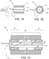
- FIG. 1A is a cross-sectional view of a fiber 101 with the optical fiber axis in the plane of the page, in accordance with some embodiments.
- FIG. 1B is a cross-sectional view of the double-clad, single core fiber 101 with the optical fiber axis perpendicular to the plane of the page, in accordance with some embodiments.
- a multi-clad optical fiber is coupled to an input and/or output of a CLS.
- optical fiber 101 is a double clad optical fiber.
- the multi-clad fiber is a triple clad optical fiber. Additional core and/or cladding layers are also possible (e.g., multi-core, quad-clad, etc.)
- Fiber 101 may have any refractive index profile (RIP) suitable for a multi-clad fiber.
- RIP refractive index profile
- the term "refractive-index profile” or "RIP” refers to the refractive index as a function of position along a line (e.g., y axis in FIG. 1A ) or in a plane (e.g. x-y plane in FIG. 1B ) perpendicular to the fiber axis (e.g., z-axis in FIG. 2A).
- fiber 101 is angularly symmetric, in which case the 1D RIP is identical for any azimuth angle.
- RIP may vary as a function of an azimuth angle about the fiber axis.
- fiber 101 has a radially symmetric RIP with a central core 105, and an inner cladding 110, which is annular and encompasses core 105.
- Inner cladding 110 is surrounded by an annular outer cladding 115.
- Core 105, inner cladding 110, and outer cladding 115 can each have any RIP including, but not limited to, a step-index and graded-index.
- a "step-index fiber" has a RIP that is substantially flat (refractive index independent of position) within fiber core 105.
- Inner cladding 110 may also have a substantially flat RI over cladding diameter D Clad .
- the RIP of fiber 101 may be stepped at the interface between core 105 and inner cladding 110.
- core 105 and inner cladding 110 may have a "graded-index" in which the RI varies (e.g., decreases) with increasing radial position (i.e., with increasing distance from the core and/or cladding axis).
- Core 105 may be suitable for single-mode or multimode propagation of light.
- Inner cladding 110 may have an area larger than that of the core, may also have a higher NA (numerical aperture) and may support a large number of propagation modes.
- Core 105 and inner cladding 110 may have any suitable composition (e.g., glass).
- Outer cladding 115 may be a polymer or also glass, for example.
- core 105 and inner cladding 110 is illustrated as being concentric, it need not be. Core 105 may also be a variety of shapes other than circular, such as, but not limited to annular, polygonal, arcuate, elliptical, or irregular. Core 105 and inner cladding 110 in the illustrated embodiments are co-axial, but may alternatively have axes offset with respect to one another. As shown in FIG. 1A , inner cladding 110 has an average outer diameter D Clad , while core 105 has an average outer diameter D Core . Diameters D Clad and D Core are illustrated to be constants about the central fiber axis in the longitudinal direction (z-axis in FIG. 1A ).
- fiber 101 is multi-mode (MM) fiber and the core diameter D Core is in the range of 10-100 micron ( ⁇ m) while the inner cladding diameter D Clad is in the range of 200-1000pm, although other values for each are possible.
- MM multi-mode
- FIG. 1C is a cross-sectional view of a fiber apparatus 102, in accordance with some embodiments.
- fiber apparatus 102 includes two lengths of (double clad) fiber 101 coupled to opposite ends of a CLS that comprises a fiber length 103.
- the lengths of fiber 101 may be coupled to fiber length 103 in any suitable manner.
- core 105 and inner cladding 110 are continuous between the lengths of fiber 101 and fiber length 103 such that fiber length 103 is merely a portion of fiber length 101.
- fiber length 103 is spliced, or otherwise joined end-to-end to the lengths of fiber 101 with the axes of the core 105 and inner cladding 110 substantially aligned with the corresponding axes of fiber length 103.
- a splice for example may be a single fusion of two fiber-end faces that have compatible cleave angles (e.g., substantially orthogonal to the longitudinal fiber axis, or z-dimension in FIG. 1C ).
- fiber length 103 is coupled to the lengths of fiber 101 by an optical connector (i.e., a fiber-to-fiber coupler) lacking an air gap between end faces of fiber lengths 101 and 103, or a mechanical splice in which there is an air gap between end faces of fiber lengths 101 and 103.
- an optical connector i.e., a fiber-to-fiber coupler
- Fiber length 103 may comprise any finite length of fiber within which recessed surface regions 150 are located.
- fiber length 103 lacks an outer cladding material (e.g., lacks outer cladding 115), which for example may have been stripped away during a CLS fabrication process.
- an outer surface including recessed surface regions 150
- outer cladding 115 may be present within at least some regions or locations of fiber length 103.
- outer cladding 115 may only be absent where recessed surface regions 150 are located.
- fiber length 103 comprises an outer cladding material (not depicted).
- a suitable material may be applied as an outer coating over inner cladding 110 within fiber length 103, and such a material may be different than that of outer cladding 115.
- recessed surface regions 150 are to strip light propagating with inner cladding 110. Such light may be propagating to/from fiber lengths 101 and would propagate through fiber length 103 as well, but for waveguide perturbations associated with recessed surface regions 150 and/or a lack of outer cladding 115. Cladding light denoted by arrow 111 in FIG. 1C may experience total internal reflection (TIR), or nearly so, until encountering recessed surface regions 150 where cladding light 111 loss from the waveguide becomes high.
- TIR total internal reflection
- cladding light It is generally desirable to remove cladding light gradually over a length of fiber (e.g., fiber length 103), for example to control the density of power dissipation, and to provide sufficient heat sinking as light stripped from inner cladding 110 may be predominantly converted to heat. Overheating the fiber or other components (e.g., ferrules, etc.) is generally undesirable.
- Some fiber system components have temperature limits below 100° C, and where an outer cladding 115 comprises a polymer, the upper limit on continuous operating temperature can be less than 85° C, for example.
- a CLS may be thermally coupled to any suitable heat sink, such as but not limited to, a passive heat exchanger operable to transfer heat generated from cladding light to a fluid medium, such as ambient air or a liquid coolant.
- fiber apparatus 102 comprises a heat exchanger that includes an absorptive mass or block 120 machined to surround fiber length 103 with free space 116 between an interior surface of block 120 and recessed surface regions 150. Light lost within fiber length 103 is to impinge block 120.
- Block 120 may comprise one or more materials that are absorbing within a band of the cladding light.
- Block 120 advantageously also has high thermal conductivity to spread heat to an exterior surface where it may interface with an external fluid medium (e.g., air).
- Block 120 may be a metal, such as, but not limited to, a stainless steel.
- heat sink block 120 surrounds the entire fiber length 103 and overlaps a portion of fiber lengths 101.
- fiber length 103 may have any number of bends, and may for example comprise a one or more wraps about a mandrel having a suitable radius of curvature, which may for example induce bend losses from inner cladding 110.
- recessed surface regions 150 do not significantly perturb light propagating within core 105.
- recessed surface regions 150 may have a depth D, along a ray perpendicular to the cladding axis, that is less than the annular thickness of inner cladding 110 (e.g., D ⁇ R clad -R core ).
- Recessed surface regions 150 may have any topology. In the example illustrated in FIG. 1C , recessed surface regions 150 have a depth that varies over the longitudinal fiber length. Variation in the depth may be a result of a beam profile of a laser employed to form the recessed surface region, or may be the result of modulations in power of a laser employed to form the recessed surface regions, for example.
- recessed surface regions 150 have a substantially Gaussian profile along the z-dimension. Such a profile may be associated with the profile of a minimum spot size of a focused laser beam with individual ones of recessed surface regions 150 being a laser-drilled hole, or recess, associated with the minimum laser spot size.
- recessed surface regions 150 illustrated in dashed line are at a different angular position than those shown in solid-line profile, and further illustrate a polygonal boundary that intersects the reference cylindrical surface of inner cladding 110.
- the boundary of an individual recessed surface region 150 is an ellipse, for example associated with the minimum laser spot diameter and the nominal outer circumference of the inner cladding.
- a minimum recessed surface region 150C is further illustrated in FIG. 2 , which is an isometric view of fiber length 301, in accordance with some cylindrical fiber embodiments.
- an arc length A3 is only slightly larger than longitudinal length L3 (which may be approximately equal to a secant of arc length A3). For such embodiments, there may be little difference between the transverse width (x-dimension), and longitudinal length (z-dimension) of the boundary.
- a recessed surface region may have a varying depth profile along a length associated with raster scan path of a laser beam employed to form the recessed surface region.
- recessed surface regions 150 are directional, each being a trench, or notch, that may extend a length longer than its width in a direction parallel to the transverse width of the fiber, parallel to the longitudinal length of the fiber, or skewed somewhere therebetween.
- recessed surface regions are positioned at more than one angular position about the axis of an inner cladding.
- a greater circumference of the cladding may be perturbed, increasing stripping efficiency and uniformity across the multiplicity of optical modes that may be propagating within the cladding.
- the dashed line boundaries illustrate recessed surface regions 150 that are approximately orthogonal to those drawn in solid line profile.
- a recessed surface region 150A is shown in partial cross-section to further illustrate the recessed surface profile.
- Recessed surface region 150A, along with recessed surface regions 150B, 150C, 150D, 150E, and 150F exemplify a plurality of recessed surface regions 150.
- Each of the recessed surface regions 150 may be parameterized, at least in part, by boundary arc length A, boundary longitudinal length L, radial depth D, and an angular boundary position, given the angular coordinate, or angular position, ⁇ .
- the plurality of recessed surface regions 150 may be further parameterized, at least in part, by a longitudinal spacing S between longitudinally adjacent recessed regions. Relative angular positions and longitudinal spacing S may define the spatial distribution of recessed surface regions 150 for given region boundaries.
- recessed surface region 150A extends over longitudinal length L1 that is associated with some portion of fiber length 103.
- Recessed surface region 150A similarly has a maximum arc length A1 associated with central angle ⁇ 1, and perpendicular to fiber axis 206 (i.e., parallel to the x-axis).
- arc length A1 may be a minimum physical dimension of a recessed region boundary, for example associated with a spot diameter of a laser intersecting a cylindrical outer surface of inner cladding 110 at some angle of incidence.
- the beam spot for example may intersect a secant of inner cladding 110 that is substantially equal to the beam spot diameter if the angle of incidence is normal to tangent of the cladding surface.
- arc length A1 may vary. In some exemplary embodiments, arc length A1 is significantly less than inner cladding diameter D clad . In some advantageous embodiments, arc length A1 is less than one-half of inner cladding diameter D clad , and may be as little as 15-20% of the inner cladding diameter D clad . For example, in some embodiments where inner cladding diameter D clad is between 250 and 500 ⁇ m, maximum arc length A1 is less than 100 ⁇ m, and may be as little as 75 ⁇ m, or even less (e.g., 50-60 ⁇ m). With such small arc length, a recessed region may minimally impact mechanical properties of fiber length 103.
- longitudinal length is approximately equal to the arc length.
- a recessed surface region may have a longitudinal length that is advantageously larger than the maximum arc length, in which case the longitudinal length may be a physical dimension defined, for example, by a scan path of a laser.
- a greater longitudinal length may increase stripping efficiency and/or uniformity across the set of modes propagating within the inner cladding.
- longitudinal length L1 is greater than arc length A1.
- longitudinal length L1 may vary from 100 ⁇ m to many millimeters (e.g., 150-400mm).
- Recessed surface region 150A has a maximum recess depth D1 located at reference fiber radius 207.
- Recess depth D1 may vary from any non-zero value to an upper bound that is somewhat less than 50% of inner cladding diameter D clad (e.g., less than 35% of D clad ) to ensure recessed surface region 150A does not punch through to core 105.
- Recess depth D1 may have a physical dimension comparable to (e.g., slightly smaller than) arc length A1. For some exemplary embodiments where arc length A1 is less than 100 ⁇ m, recess depth D1 is between 10 and 75 ⁇ m.
- a location of a recessed surface region within fiber length 103 may be further parameterized by angular position ⁇ about fiber axis 206, which may be defined to bisect arc length A1.
- Angular position ⁇ may be further defined as 0° at some reference position (e.g., falling on fiber radius 207, such that recessed surface region 150A has an angular position ⁇ of 0°).
- longitudinally adjacent recessed surface regions are nonoverlapping.
- no recessed surface regions have any longitudinal overlap.
- longitudinal length L1 does not overlap with longitudinal length L2, and instead is separated by a longitudinal spacing S1.
- Longitudinal length L2 likewise does not overlap with longitudinal length L3, and longitudinal length L3 does not overlap with longitudinal length L4, etc. Avoiding longitudinal overlap may ensure fiber length 103 maintains sufficient mechanical strength.
- recessed surface regions may have longitudinal overlap and still maintain sufficient mechanical strength, for example where a cladding diameter is large compared to the arc length of individual recessed surface regions (e.g., an arc length less than 75 ⁇ m for a cladding diameter over 250 ⁇ m).
- the number of such recessed surface regions occupying a same longitudinal length may be increased in an inverse relationship with the ratio of recess arc length/fiber diameter.
- spreading recessed surface regions having a given cumulative arc length over an entire circumference of a fiber within a same longitudinal length may offer greater mechanical strength than is possible for a single recessed surface region having an equivalent arc length. Stripping efficiency and/or uniformity may also be superior.
- longitudinal spacing S between them may vary from zero (in which case adjacent recessed surface regions may abut end-to-end) to an arbitrarily large spacing.
- a larger stripping rate may be achieved for a smaller average longitudinal spacing S, so an average longitudinal spacing S may be set as a function of desired stripping rate, and length of fiber available to implement the CLS.
- arc length A1 may vary over longitudinal length L1.
- a laser spot size or angle of incidence may be modulated along a scan path to form recessed surface region 150A.
- recess depth D1 may vary over longitudinal length L1.
- a laser power may be modulated along a scan path to form recessed surface region 150A.
- angular position ⁇ may vary over longitudinal length L1.
- fiber length 103 may be rotated about fiber axis 206 and/or a laser position may be modulated along a scan path to vary angular position ⁇ over length L1.
- one or more of arc length, longitudinal length, recess depth, angular position, or longitudinal spacing may vary across the plurality.
- a population of recessed surface regions may include two (or more) recessed surface regions with different arc lengths.
- recessed surface region 150A has an arc length A1 and recessed surface region 150A has a different arc length A2.
- a population of recessed surface regions may include two (or more) recessed surface regions with different longitudinal lengths.
- recessed surface region 150A has a longitudinal length L1
- recessed surface region 150B has a longitudinal length L2 that is different than length L1
- recessed surface region 150C has a longitudinal length L3 that is different than lengths L1 and L2.
- a population of recessed surface regions may include two (or more) recessed surface regions with different recess depths.
- a population of recessed surface regions may include two (or more) recessed surface regions with different angular positions ⁇ .
- Cladding light losses may be increased by increasing the number of angular positions, particularly where arc length of each recessed surface region is minimized.
- Adding recessed surface regions at multiple angular positions about a fiber may induce more perturbations for cladding modes, therefore increasing stripping rate (loss power/fiber length).
- Recess depth D, and/or device length (e.g., fiber length 103) might then be reduced depending on design requirements.
- a first subset of recessed surface regions e.g., 150A, 150C and 150E
- a second subset of recessed surface regions e.g., 150B, 150D and 150F
- Such embodiments may, for example, induce losses in orthogonal optical modes and uniformity of losses across the modes may be improved relative to a configuration including only one of the first or second subsets of recessed surface regions.
- recessed surface regions can be positioned at any angle (e.g., 0° ⁇ ⁇ ⁇ 360°) such that the relative positions between longitudinally adjacent recessed surface regions (e.g., 150A and 150B) may also vary by any angle.
- recessed surface regions may be spaced apart by different longitudinal spacing.
- recessed surface region 150A is spaced apart from recessed surface region 150B by longitudinal spacing S1, which is different than longitudinal spacing S2 between recessed surface region 150B and recessed surface region 150C. Spatial distribution of recessed surface regions may therefore vary within a CLS, and may be tuned to achieve a desired power loss and loss uniformity, for example to avoid hot spots within the CLS.
- the above variations described may be implemented according to some regular (predictable) pattern within a CLS, for example according to a predetermined mathematical function (e.g., linear, monotonic, etc.).
- a predetermined mathematical function e.g., linear, monotonic, etc.
- FIG. 2 One example of a predictable pattern is shown in FIG. 2 where the recessed surface regions 150A-150F are alternated between the same two angular positions ⁇ (e.g., 0° and 90°).
- Varying longitudinal length L1 through L3, etc. (e.g., increasing/decreasing) according to a predetermined function is another example of implementing a regular pattern within a CLS.
- the same subset of optical modes propagating within inner cladding 110 may experience the highest losses, while other optical modes experience considerably lower losses.
- the parameter value variations described above may therefore also be implemented according to some irregular (unpredictable) pattern within a CLS, for example according to a probability distribution function (PDF).
- PDF probability distribution function
- a CLS includes a plurality of recessed surface regions
- the individual recessed surface regions differ from each other in a random manner characterized by probability distribution functions associated with the boundary and/or spatial position parameter values. For example, values of any (or all) of parameters described above, such as, arc length, longitudinal length, depth, angular position, and longitudinal spacing, may be randomized.
- Each parameter value characterizing the recessed surface regions may have an associated PDF (or probability mass function (PMF) if the parameter values are made discrete).
- the PDF (PMF) for at least one of the parameters is a uniform, or normal, probability distribution function.
- the PDF for all of the parameters characterizing the recessed surface regions is a uniform, or normal, probability distribution function.
- the PDF differs between two, or more, of the parameters characterizing the recessed surface regions. Random values of each parameter may be confined to within any range predetermined to be suitable for the parameter, with the PDF for each then defining the probability that that parameter assumes a particular value within the permissible range.
- a depth of recessed surface regions is statistically random.
- recessed surface regions 150A-150F may have a random arrangement of different depths according to a probability distribution function (e.g., a uniform, or normal, probability distribution function), which may be confined to within some acceptable range (e.g., greater than zero and less than R clad -R core , or less than 35% of D clad , etc.).
- the random variation in depth may be confined to any range predetermined to be suitable with the PDF then defining the probability that the depth assumes a particular value within the permissible range.
- angular position of recessed surface regions is statistically random. For example, in FIG.
- recessed surface regions 150A-150F may have a random arrangement of angular positions, for example according to a uniform probability distribution function.
- longitudinal spacing of recessed surface regions is statistically random.
- recessed surface regions 150A-150F may be randomly spaced apart (i.e., longitudinal spacing S1, S2, etc. is random).
- arc length or longitudinal length of recessed surface regions is statistically random.
- recessed surface regions 150A-150F may have randomized boundary dimensions (e.g., arc lengths A1, A2, etc. and longitudinal lengths L1, L2, L3, etc. are random).
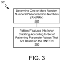
- FIG. 3 is a block diagram illustrating methods 301 for forming a CLS with multiple recessed surface regions within the CLS, in accordance with some embodiments.
- RN random numbers
- PRN pseudorandom numbers
- Any known randomization technique may be employed at block 304.
- a seeded deterministic algorithm may be employed to generate a pseudorandom number according to a uniform PDF (or uniform PMF).
- a natural process that is unpredictable e.g., atmospheric noise
- Random values determined at block 304 may be confined to within a range predetermined to be suitable for a given parameter.
- a randomized value for any (or all) of the parameters described above is determined at block 304 for the entire set of recessed surface regions that a CLS is to include. Where the parameters characterizing a recessed surface region are independent, a set of randomized values for each parameter may be determined.
- features are patterned into the inner cladding according to the set(s) of random numbers determined at block 304.
- the random numbers may be used indirectly, for example to define a control parameter of a fabrication process that is employed to pattern the set of recessed surface regions.
- a set of the generated random values may define a set of longitudinal indexing values that will set spacing between consecutively fabricated ones in the set of recessed surface regions.
- FIG. 4A is a plan view of fiber length further illustrating randomized spacing of recessed surface regions, in accordance with some embodiments.
- a laser traverses a first scan path 451 in a first raster direction, followed by a second scan path 452 in a second (return) raster direction. Additional consecutive scan paths are further illustrated in FIG. 4A .
- One recessed surface region is fabricated for each scan path 451, 452, etc.
- the scan paths are substantially orthogonal to the longitudinal axis of fiber length 103.
- Each scan path results in a recessed surface region thathas a longitudinal length L that is dependent on laser spot size and/or angle of incidence of the beam emanating from the laser during fiber processing.
- length L is smaller than the scan path length, which may generate recessed surface regions having an arc length that exceeds the longitudinal length.
- transverse scan paths are illustrated in FIG. 4A for the sake of clarity as well as to emphasize that randomization within a set of recessed surface regions does not require the recessed surface regions to have any particular boundary dimensions. Randomization of recessed surface regions may however be combined with advantageous boundary dimensions in some further embodiments.
- Recessed surface regions resulting from the scan paths illustrated in FIG. 4A are spaced apart by a longitudinal spacing S that may be a function a relative displacement between fiber length 103 and a laser beam following the programmed scan paths.
- the parameter determining the longitudinal indexing distance between scan paths 451 and 452 may be randomized to achieve a desired randomization of longitudinal spacing S within the final set of recessed surface regions.
- longitudinal length L is constant over the fiber length 103 to emphasize the irregular, non-periodic longitudinal spacing S.
- FIG. 4B is a cross-sectional view of a fiber illustrating randomized angular positions of recessed surface regions, in accordance with some embodiments.
- Angular positions ⁇ 1 , ⁇ 2 , ⁇ 3 , etc. may be randomized over complete set of recessed surface regions of a CLS.
- a set of the generated random values may define a set of angular position values that will define a center location of a laser beam scan path relative to an outer circumference of the inner cladding.
- a set of the generated random values may define a set of positions of a stepper motor that is to rotate fiber length 103 about the fiber axis in concert with laser ablation of the set of recessed surface regions.
- FIG. 4C is a plan view of a fiber length 103 illustrating randomized depths of recessed surface regions, in accordance with some embodiments.
- Different laser power levels are represented by the different field lines, for example associated with scan paths 410, 411, 412 and 413.
- first scan path 451 is in a first raster direction, followed by second scan path 452 in a second (return) raster direction. Additional consecutive scan paths are further illustrated in FIG. 4C with the resulting recessed surface regions spaced apart by a constant longitudinal spacing S and constant longitudinal length L over the fiber length 103 to illustrate only an irregular, non-periodic variation in laser power.
- another set of the generated random values may define a set of beam spot sizes and/or angles of incidence of a laser fabricating the set of recessed surface regions. Such values may, for example, vary a minimum arc length and/or longitudinal length of the set of recessed surface regions.
- another set of the generated random number values may define a scan path length that a laser will employ for fabricating the set of recessed surface regions.
- a similar randomization process may be applied to parameters of any of other known patterning techniques suitable for forming recessed surface regions to vary their boundary shape and/or spatial distribution according to a normal probability distribution function.
- block 306 may be performed any number of times, for example to fabricate a plurality of CLS fiber lengths in a manufacturing line.
- the outer cladding may be removed from at least a portion of the fiber length.
- the outer cladding is removed in its entirety from a center portion of the received fiber length, while the outer cladding is retained in its entirety at end portions of the received fiber length.
- Recessed surface regions are then formed by ablating a portion of the inner cladding in any manner that achieves the randomized parameter values.
- Another length of fiber is then received, and the same process performed.
- suitable parameter values have been determined at block 304, those same parameter values may be employed repeatedly for each fiber processed at block 306.
- randomization is at the CLS fiber level (i.e., not random across different CLS fibers).
- a recessed surface region may have a small arc length.
- a single recessed surface region may be continuous from a first end of a CLS to a second end.
- Arc length for such a long recessed surface region may be small to maintain mechanical strength of the fiber, for example.
- FIG. 5 is a block diagram illustrating methods 501 for forming a CLS having a single continuous recessed surface region, in accordance with some embodiments.
- a length of multi-clad fiber is received (e.g., of the type described in the context of fiber length 101).
- the outer cladding may be removed from at least a portion of the received fiber length.
- the outer cladding is removed in its entirety from a center portion of the received fiber length, while the outer cladding is retained in its entirety at end portions of the received fiber length.
- a recessed surface region is then formed, for example by ablating a portion of the inner cladding along the center portion of the received fiber length.
- a single recessed surface region is formed at block 506. In other embodiments however, multiple recessed surface regions may be formed at block 506, for example at different angular positions.
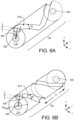
- FIG. 6A-6H are isometric views of a length of fiber within a CLS, in accordance with some further embodiments.
- a recessed surface region 610 is continuous over fiber length 103.
- the non-zero arc length A associated with a width W of the recessed surface region 610 may vary over its longitudinal length, for example according to a regular or irregular (random) pattern.
- Recess depth D may also vary along the longitudinal length of recessed surface region 610 according to a regular or irregular (random) pattern.
- the width of recessed surface region 610 may deviate from arc length A as a function of the path of recessed surface region 610.
- recessed surface region 610 has a width that is equal to arc length A.
- recessed surface region 610 may have a width significantly small than arc length A.
- Recess depth D is non-zero such that there is no fully cylindrical inner cladding along fiber length 103.
- Angular position may likewise vary along the longitudinal length of recessed surface region 610 according to an irregular (random) path pattern, as shown in FIG. 6A , or according to a regular path pattern, such as the spiral or helical groove or flute shown in FIG. 6B .
- a laser source may be employed to ablate cladding material and form recessed surface region 610.
- Width W of recessed surface region 610 may be controlled primarily by spot size of the laser source, and secondarily controlled by the amount of laser energy coupled into inner cladding 110 during ablation.
- Depth D of recessed surface region 610 may be controlled primarily by the amount of laser energy coupled into inner cladding 110 during ablation, which is a function of at least laser power, pulse length, number of pulses, or a pulse overlap ratio. In some embodiments, depth is varied along the longitudinal length of recessed surface region 610 by adjusting the overlap of pulses so that the depth has a "ripple" shape along the helix.
- Fiber length 103 occupied by the CLS structure may be controlled by combining the ablation time and rate of linear displacement (speed).
- a laser may be scanned at a longitudinal rate while the fiber is rotated about its axis.
- a fiber may be displaced longitudinally along the fiber axis while the laser source is rotated about the fiber axis.
- each groove has a transverse width W, and each groove may span the outer circumference of inner cladding 110 according to a helical function centered about the fiber axis that results in the groove having an arc length A at its intersection with a transverse plane of the fiber.
- each groove or flute, as well as the groove count, and groove pitch may all be optimized to achieve certain CLS performance requirements, such as a peak temperature, and/or stripping rate (e.g., some dB/unit length), and/or stripping efficiency (e.g., some threshold dB level for the CLS), and/or fiber strength.
- CLS performance requirements such as a peak temperature, and/or stripping rate (e.g., some dB/unit length), and/or stripping efficiency (e.g., some threshold dB level for the CLS), and/or fiber strength.
- a helical groove may have advantages over a notch (e.g., one having a longest length transverse to the fiber axis) because the helical groove can continuously strip cladding light over its entire longitudinal length, allowing for shorter, more efficient clad light strippers while limiting the transverse fiber dimension of the groove to only the arc length A.
- the pitch P of the helical structure illustrated in FIG. 6B defines the number of helical grooves within fiber length 103.
- pitch P in addition to helicity (handedness), groove depth D and width W may all be determined to achieve a desired stripping efficiency/fiber length.
- the helix pitch P may be significantly larger than the length of the CLS structure so that the number of turns within the length of a CLS structure is less than 1 (e.g., 1 ⁇ 4 turn, 1 ⁇ 2 turn, 3 ⁇ 4 turn, etc.).
- the helix pitch P may also be substantially equal to the length of the CLS structure so that there is approximately one full turn in the helix over the length of the CLS.
- Pitch P may be controlled during CLS fabrication, for example, through control of linear and rotational speeds. A multiple of time per full rotation and linear speed may be varied over fiber length 103 if pitch P is to be varied.
- the helix pitch P is significantly shorter than the length of the CLS structure so that the number of turns within the length of a CLS structure is significantly more than one (e.g., 3 turns, 5 turns, 10 turns, etc.).
- helix pitch P is approximately I/6th the CLS fiber length 103 such that there are 6 full turns.
- helix pitch P may be smaller than groove width W such that within fiber length 103 there is no portion of fiber that has the full cladding diameter Dciad.
- there is a helical ridge 613 that has some less diameter less than Dciad, which depends on groove width W, groove depth D, and helix pitch P.
- At least one of the pitch P, the groove depth D, and/or groove width W varies along the length of the helical groove.
- depth D, and/or groove width W may increase monotonically with distance from one end of the CLS (e.g., proximal to a cladding light source end of a fiber system).
- FIG. 6D illustrates an example, where recessed surface region 610 follows a helical path with a first pitch Pi over a first portion of fiber length 103 and then follows a helical path with a second, larger, pitch P 2 over a second portion of fiber length 103.
- groove width W and/or groove depth D may also be varied along with groove pitch.
- a helical groove structure may also be symmetrical over its length with a parameter of the groove varying from a center of the CLS structure to opposite ends of the CLS structure according to substantially the same function.
- groove pitch P, groove depth D, and/or groove width W may each increase or decrease with proximity to each end of the CLS.
- a first helical structure with low stripping efficiency can remove a portion, but not all the cladding light.
- FIG. 6E is an illustration of a helical structure where a helical recessed surface region 610 has a larger helix pitch P 2 within two end fiber lengths 103B that are on opposite sides of a center fiber length 103A in which the recessed surface region 610 has a smaller helix pitch P 1 .
- This configuration may, for example, reduce the stripping rate within the end fiber lengths 103B where cladding light first enters the CLS.
- Heating over the CLS may therefore be spread over fiber lengths 103A 103B.
- Alternative configurations for example where two end portions with a smaller pitch (e.g., Pi) are on opposite sides of a center portion having a larger groove pitch (e.g., P 2 ) are also possible as there may be many sections of alternating efficiency spanning a CLS fiber length.
- a CLS may include two or more helical grooves.
- a CLS comprising multiple helical structures may further enable optimization of the CLS to meet performance requirements while maximizing fiber strength for reliability.
- Using multiple helical structures is also advantageous for design and manufacturing as each helical groove can be characterized individually for performance characteristics, and combined to tailor the CLS to specific application requirements.
- Each of the plurality of helical structures may have different start and end points, and there may be any number of helical structures with 2-5 helices being an exemplary range for a 100-180 ⁇ m diameter cladding.
- Multiple helical structures can be separated by a longitudinal distance along the fiber axis, or can be separated angularly about the fiber axis (e.g., with multiple helical structures about the same length of fiber).
- a plurality of helical grooves may be either congruent or intersecting. The handedness may also differ across a plurality of helical structures within a CLS.
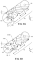
- FIG. 6F illustrates an exemplary CLS fiber structure that includes a first recessed surface region 610A that varies from a first helix pitch P 1 within fiber length 103A to a second helix pitch P 2 within an adjacent fiber length 103B.
- the CLS fiber structure further includes a second recessed surface region 610B that also varies from helix pitch P 1 within fiber length 103C to the second helix pitch P 2 within the adjacent fiber length 103B.
- recessed surface region 610A has a first handedness (e.g., turning right down the z-axis with increasing proximity to fiber length 103B from a first end) while recessd surface region 610B has a second handedness (e.g., turning right down the z-axis with increasing proximity to fiber length 103B from a second end).
- first handedness e.g., turning right down the z-axis with increasing proximity to fiber length 103B from a first end
- recessd surface region 610B has a second handedness (e.g., turning right down the z-axis with increasing proximity to fiber length 103B from a second end).
- Within fiber length 103B there are therefore two helical recessed surface regions 610A and 610B located at different angular positions about the fiber axis.
- the example in FIG. 6F is therefore symmetrical about a transverse plane within fiber length 103B.
- FIG. 6G illustrates an exemplary CLS fiber structure that includes a plurality of helical recessed surface regions 610A and 610B, which are separated by an angular separation angle ⁇ .
- Recessed surface region 610A has a helix pitch P A and recessed surface region 610B has a helix pitch P B .
- helical pitches P A and P B may be substantially equal so that the helical patterns are congruent with angle ⁇ being constant over CLS fiber length 103.
- helical pitches P A and P B differ, and angle ⁇ varies over CLS fiber length 103. Either one, or both, of helical pitches P A and P B may be varied over fiber length 103.
- Either one, or both, of helical pitches P A and P B may also be varied over fiber length 103.
- Recessed surface region 610A has a groove depth D 1 and groove width Wi, that may vary, or be constant, over fiber length 103.
- Recessed surface region 610B likewise has a groove depth D 2 and groove width W 2 , that may vary, or be constant, over fiber length 103. Groove depths D 1 , D 2 and groove widths W 1 , W 2 may all be turned independently.
- FIG. 6H illustrates an exemplary CLS fiber structure that includes a plurality of helical recessed surface regions 610A and 610B having opposing handedness. As shown, the helical structures cross each other at an intersection 615. Such intersections may be points of higher stripping rate such that the density of intersections 615 within a CLS structure may also be a design parameter that can be optimized. Depending on the techniques employed to fabricate recessed surface regions 610A and 610B, groove depth D may be greater within an intersection 615. The lateral dimensions, as well as the density, of intersections 615 may be controlled by the groove depths D 1 , D 2 , groove widths Wi, W 2 and helical pitches P A and P B .
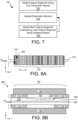
- FIG. 7 is a block diagram illustrating methods 701 for forming a CLS having end-to-end segmented surface regions, in accordance with some embodiments.
- a fiber processing system e.g., including a laser processing head
- the fiber processing system parameter values are updated, for example either according to a predetermined predictable (i.e., mathematical) function, or according to an unpredictable (i.e., random) function.
- the fiber processing system ablates a second recessed surface region segment into the inner cladding using the updated set of parameter values. Between blocks 702 and 706, the fiber may be displaced relative to the laser of the fiber processing system by an amount that ensures the first and second segments abut.
- each segment may be patterned into the inner cladding with a discrete raster scan of a laser. Each scan may abut the next.
- a laser may follow a single scan path and properties of the laser process modulated during the single scan (e.g., that follows a predetermined path defined by angular position and longitudinal position according to a helical function or other continuous function).
- FIG. 8A is a plan view of fiber length 103 illustrating end-to-end segmentation of a recessed surface region, in accordance with some embodiments.
- a longitudinal indexing between laser beam scan paths 451 and 452 is such that scan paths 451 and 452 ablate two abutting recessed surface region segments (i.e., longitudinal spacing S is no more than zero).
- longitudinal spacing S is no more than zero.
- different filed lines represent different laser output power levels employed at some point within the scan path.
- FIG. 8B is a cross-sectional view of CLS 801 that includes the components introduced above in the context of FIG. 1C .
- CLS 801 however further illustrates recessed surface region 150 that extends the entirety of fiber length 103 and segments within recessed surface region 150 all have non-zero recess depths that vary between the segments. Such depth variation may induce mode mixing and/or losses along the entire length of a recessed surface region.
- Such randomization may be implemented substantially as described elsewhere herein. In other embodiments, there may be a regular pattern to the variation.
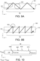
- FIG. 9A and 9B are plan views of inner cladding 110 illustrating spot sizes 931, 932 and 933 and raster paths 951 and 952 suitable for forming a continuous recessed surface region in a cladding layer, in accordance with some embodiments.
- scan path 951 is a zig-zag pattern with x-z vector motion.
- both arc length and angular position of a resulting recessed surface region may be modulated.
- ablating along scan path 951 may generate a continuous recessed surface region that spans substantially the entire transverse width of inner cladding 110.
- FIG. 9B illustrates a saw-tooth scan pattern having a shorter period.
- FIG. 10 is a cross-sectional view of a length of fiber within a CLS illustrating a recessed surface region 150 that has continuous depth modulation, in accordance with some embodiments.
- continuous depth modulation disturbances along fiber length 103 may induce mode mixing and/or losses along the entire length of a recessed surface region.
- the entire recessed surface region 150 being recessed from the nominal outer diameter of the inner cladding (D clad )
- periodic troughs e.g.., 1065 and 1067
- Recessed surface region 150 further comprises periodic ridges (e.g., 1072 and 1074) that also become deeper (e.g., relative to D clad ) over fiber length 103.
- periodic ridges e.g., 1072 and 1074
- D CLS cladding diameter
- the local variations in depth may be the result of discrete laser ablation events, each associated with a separate segment, for example.
- the global variations in depth may be the result of an increase in laser output power for successive segments, for example.
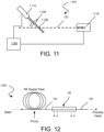
- FIG. 11 is a schematic of a laser fiber processor (processing system) 1101, which is operable to fabricate a CLS, in accordance with some embodiments.
- Processing system 1101 includes a laser 1115.
- Laser 1115 in some exemplary embodiments is a CO 2 laser, which emits at wavelengths that are absorbed by cladding material (e.g., silica glass).
- Laser 1115 may for example, operate wavelength locked at 10.6 ⁇ m, or 9.6 ⁇ m at a peak pulse intensity suitable for elevating the temperature of an irradiated zone to the evaporation temperature of the cladding.
- Laser 1115 outputs through a delivery fiber, which in some embodiments further includes a beam conditioner 1120.
- Beam conditioner 1120 may include free-space optics and/or fiber optics for focusing, for example.
- beam conditioner 1120 comprises one or more lenses comprising a material of suitable index, such as ZnSe. Exiting the lens, the light beam may focus to a spherical or aspherical spot size 1130 at some working distance.
- Spot size 1130 may vary with implementation. For example, a larger spot size (e.g., arrived at through defocusing optics) of 250 ⁇ m, or more, may generate large, smooth features that can be expected to maintain high mechanical strength of the fiber.
- Spot size 1130 may alternatively be significantly smaller than the inner cladding diameter of a fiber.
- spot size 1130 may be significantly less than 100 ⁇ m, less than 75 ⁇ m, and even no more than 50 ⁇ m.
- the width of a recess formed by a laser of a given spot size may be significantly smaller than the spot diameter.
- a spot size of over 200 ⁇ m may render a recess of less than 100 ⁇ m in diameter.
- the spot may be significantly smaller than the outer diameter of an inner cladding, which may be 125-660 ⁇ m, for example.
- Processing system 1101 further includes a motorized translation and/or rotation stage 1110. Stage 1110 operable for linear translation in three axes (x,y,z), tiltable in the plane of incidence of the laser, and rotatable about an axis of fiber 101 (drawn in dashed line in FIG. 11 as the fiber is only a workpiece of processing system 1101 and not part of the processing system 1101). Processing system 1101 further comprises a computer controller 1105 communicatively coupled to laser 1115 and to stage 1110. Computer controller 1105 is operable to control laser 1115 and stage 1110 in concert to ablate any predetermined regions of a workpiece (e.g., fiber 101).
- a workpiece e.g., fiber 101
- a recessed surface region may be patterned at a desired location and with desired boundary dimensions by irradiating a portion of the cladding with one or more laser pulses.
- the stage (or laser) may then be indexed to a next power, the beam refocused on another location of the fiber to pattern the next recessed surface region.
- FIG. 12 is a schematic of a multimode fiber laser processing system 1201 according to some embodiments.
- system 1201 includes a fiber 101 that includes an active length.
- a seed light source is coupled to fiber 101, for example at an input coupler.
- the seed light source may be, for example, a diode pumped solid-state laser, a quantum cascade laser, a passively q-switched laser, a diode laser, a mode-locked laser, a fiber laser, or a combination thereof.
- the seed light source may be operable for any of continuous wave output, pulsed output, or a wavelength chirped pulsed output, for example.
- the seed light source is a Nd:YAG laser.
- rare-earth dopant(s) are present within the active length of fiber 101.
- such dopants may be within a core of the fiber, resulting in an optical gain spectrum that at least partially overlaps the spectrum of the seed light source.
- Ytterbium may be used as a rare-earth dopant suitable for a seed laser source including wavelengths between 1030 nm and 1090 nm.
- other rare-earth dopants can be used.
- fiber 101 is a double clad fiber where the seed light is amplified in the core by pump light that is propagated within an inner cladding surrounding the core.
- the optical pump has an output spectrum that at least partially overlaps the absorption spectrum of active length of fiber 101.
- the optical pump may be a fiber-coupled laser diode operable to emit near 976 nanometers.
- the output from optical pump source may be optically coupled to the active length of fiber 101 with any known pump combiner.
- the pump may be operable in a counter-propagating configuration, or may be introduced upstream of the active length of fiber 101 such that light from the seed light source and the pump light are co-propagating within the active length of fiber 101, for example.
- fiber 101 includes CLS 102, which is further coupled to another length of fiber 101 (e.g., double-clad fiber) operable as a delivery fiber.
- the delivery fiber may be further coupled to a process head, for example.
- CLS 102 may have one or more of the features described elsewhere herein. Downstream of CLS 102 is a delivery fiber, which in the illustrated example includes a process head. Output power at the delivery fiber may vary, for example from 500W to 3KW.
Landscapes
- Physics & Mathematics (AREA)
- Electromagnetism (AREA)
- Optics & Photonics (AREA)
- Engineering & Computer Science (AREA)
- Plasma & Fusion (AREA)
- General Physics & Mathematics (AREA)
- Lasers (AREA)
- Light Guides In General And Applications Therefor (AREA)
Claims (13)
- Un appareil à fibre optique, comprenant :des première et deuxième longueurs de fibre, chacune comprenant une gaine extérieure par-dessus une gaine intérieure qui est par-dessus un coeur ; etun suppresseur de lumière de gaine, CLS, comprenant une troisième longueur de fibre (103) qui couple optiquement la première longueur de fibre à la deuxième longueur de fibre, la troisième longueur de fibre comprenant en outre un coeur (105), et une gaine intérieure (110) qui présente une ou plusieurs rainures hélicoïdales (610) destinées à perturber de la lumière qui se propage dans la gaine intérieure, les une ou plusieurs rainures hélicoïdales s'étendant de manière continue sur la troisième longueur, caractérisé en ce que les une ou plusieurs rainures hélicoïdales présentent un pas d'hélice qui varie sur la troisième longueur.
- L'appareil à fibre optique de la revendication 1, où les une ou plusieurs rainures hélicoïdales (610) présentent une profondeur ou largeur qui varie sur la troisième longueur.
- L'appareil à fibre optique de la revendication 1, où des rainures individuelles parmi les rainures présentent le pas d'hélice qui est plus court que la troisième longueur.
- L'appareil à fibre optique de la revendication 3, où les une ou plusieurs rainures hélicoïdales (610) effectuent deux tours ou plus autour d'un axe de fibre sur la troisième longueur.
- L'appareil à fibre optique de la revendication 1, où les une ou plusieurs rainures hélicoïdales (610) comprennent une seule rainure hélicoïdale.
- L'appareil à fibre optique de la revendication 1, où les une ou plusieurs rainures hélicoïdales (610) comprennent deux rainures hélicoïdales ou plus espacées longitudinalement ou angulairement.
- L'appareil à fibre optique de la revendication 6, où les deux rainures hélicoïdales (610) ou plus se croisent.
- L'appareil à fibre optique de la revendication 7, où les deux rainures hélicoïdales ou plus présentent un sens de rotation opposé.
- Un procédé pour former un appareil à fibre optique, le procédé comprenant :réception (502) d'une fibre optique comprenant une première longueur de fibre séparée d'une deuxième longueur de fibre par une troisième longueur de fibre, chacune des longueurs de fibre comprenant une gaine extérieure par-dessus une gaine intérieure qui est par-dessus un coeur ;retrait (504) de la gaine extérieure d'au moins une partie de la troisième longueur de la fibre ;évidement (506) d'une ou de plusieurs régions de surface de la gaine intérieure au sein de la partie de la troisième longueur de la fibre en concentrant un point de faisceau laser sur une surface extérieure de la gaine intérieure, l'évidement comprenant le déplacement de la fibre relativement au faisceau laser longitudinalement sur une longueur de la fibre qui dépasse une largeur transversale du point de faisceau, et l'évidement comprenant la variation d'une puissance du faisceau durant le déplacement ; etvariation d'une position angulaire du faisceau laser relativement à un axe longitudinal de la fibre durant le déplacement, la variation de la position angulaire étant selon une fonction hélicoïdale, formant ainsi une ou plusieurs rainures hélicoïdales qui s'étendent de manière continue sur la troisième longueur,caractérisé en ce queles une ou plusieurs rainures hélicoïdales présentent un pas d'hélice qui varie sur la troisième longueur.
- Le procédé de la revendication 9, comprenant en outre la variation d'un angle d'incidence du laser relativement à la surface extérieure de la gaine intérieure durant le déplacement, facultativement la variation de l'angle d'incidence est selon une fonction de distribution de probabilités.
- Le procédé de la revendication 9, où la variation d'une puissance du faisceau durant le déplacement comprend en outre :avance du faisceau jusqu'à un premier emplacement sur la fibre ;ablation d'une première partie de la gaine intérieure jusqu'à une première profondeur avec une première puissance de faisceau ;avance de la position de faisceau jusqu'à un deuxième emplacement sur la fibre espacé du premier emplacement d'une distance non supérieure à une taille de point du faisceau concentré ; etablation d'une deuxième partie de la gaine intérieure jusqu'à une deuxième profondeur avec une deuxième puissance de faisceau.
- Le procédé de la revendication 11, comprenant en outre la sélection de la première puissance de faisceau et de la deuxième puissance de faisceau sur la base d'un nombre aléatoire échantillonné selon une fonction uniforme de distribution de probabilités.
- Le procédé de la revendication 9, où le déplacement de la fibre relativement au faisceau laser comprend en outre le déplacement de la fibre relativement au faisceau laser d'au moins la troisième longueur de la fibre.
Applications Claiming Priority (2)
| Application Number | Priority Date | Filing Date | Title |
|---|---|---|---|
| US201862734946P | 2018-09-21 | 2018-09-21 | |
| PCT/US2019/052241 WO2020061505A1 (fr) | 2018-09-21 | 2019-09-20 | Extracteur de lumière de gainage de fibre optique |
Publications (3)
| Publication Number | Publication Date |
|---|---|
| EP3841411A1 EP3841411A1 (fr) | 2021-06-30 |
| EP3841411A4 EP3841411A4 (fr) | 2022-06-01 |
| EP3841411B1 true EP3841411B1 (fr) | 2024-11-06 |
Family
ID=69883850
Family Applications (1)
| Application Number | Title | Priority Date | Filing Date |
|---|---|---|---|
| EP19862724.2A Active EP3841411B1 (fr) | 2018-09-21 | 2019-09-20 | Extracteur de lumière de gainage de fibre optique |
Country Status (4)
| Country | Link |
|---|---|
| US (2) | US11575239B2 (fr) |
| EP (1) | EP3841411B1 (fr) |
| CN (1) | CN112955793A (fr) |
| WO (1) | WO2020061505A1 (fr) |
Families Citing this family (12)
| Publication number | Priority date | Publication date | Assignee | Title |
|---|---|---|---|---|
| US11531162B2 (en) | 2020-03-27 | 2022-12-20 | University Of Seoul Industry Cooperation Foundation | Optical fiber device for removing cladding light, apparatus and method for etching the same |
| DE102020113731B4 (de) * | 2020-05-20 | 2024-02-08 | FiberBridge Photonics GmbH | Glasfaser und Glasfaserprodukt |
| DE102020008266B4 (de) * | 2020-05-20 | 2025-04-24 | FiberBridge Photonics GmbH | Glasfaser und Glasfaserprodukt |
| US20230258868A1 (en) * | 2020-07-14 | 2023-08-17 | Nlight, Inc. | Clad light stripper with light traps |
| JP2023019638A (ja) * | 2021-07-29 | 2023-02-09 | 株式会社アマダ | クラッドライトストリッパ及びクラッドライトストリッパの製造方法 |
| CN113866891B (zh) * | 2021-09-10 | 2023-06-23 | 中国电子科技集团公司第十一研究所 | 光纤耦合端 |
| CN114527534B (zh) * | 2022-04-24 | 2022-06-24 | 武汉锐科光纤激光技术股份有限公司 | 光纤剥模器、光纤剥模器制备方法及激光设备 |
| CN115144954B (zh) * | 2022-08-31 | 2023-01-03 | 北京凯普林光电科技股份有限公司 | 一种包层光剥离器及其制备方法 |
| US20240310592A1 (en) * | 2023-03-13 | 2024-09-19 | Cyclone Biosciences, Llc | Optical fiber termination, related devices, and fabrication of same |
| TWI903186B (zh) * | 2023-07-10 | 2025-11-01 | 萊凌科技股份有限公司 | 維持低纖核訊號傳輸損耗與剝除纖殼層能量之光纖元件製造方法 |
| CN117111204B (zh) * | 2023-10-24 | 2024-03-19 | 中国工程物理研究院激光聚变研究中心 | 光纤、包层功率剥离器及光纤激光器 |
| WO2026034108A1 (fr) * | 2024-08-07 | 2026-02-12 | 株式会社フジクラ | Fibre à âmes multiples et connecteur optique |
Family Cites Families (77)
| Publication number | Priority date | Publication date | Assignee | Title |
|---|---|---|---|---|
| GB1488792A (en) * | 1973-09-06 | 1977-10-12 | Jenkins R | Optical dielectric waveguides |
| US3891302A (en) * | 1973-09-28 | 1975-06-24 | Western Electric Co | Method of filtering modes in optical waveguides |
| JPS581105A (ja) * | 1981-06-25 | 1983-01-06 | Mitsubishi Electric Corp | 光フアイバ照光装置 |
| GB2188719B (en) * | 1986-04-02 | 1990-08-22 | Stc Plc | Optical fibres |
| CA2073162C (fr) * | 1991-07-31 | 1999-06-29 | Lee A. Danisch | Capteur de position et de deformation a fibre optique |
| US5222795A (en) * | 1991-12-26 | 1993-06-29 | Light Sciences, Inc. | Controlled light extraction from light guides and fibers |
| US6314220B1 (en) * | 1995-03-13 | 2001-11-06 | Templex Technology, Inc. | Segmented complex fiber gratings |
| DE19681304T1 (de) * | 1995-03-24 | 1998-04-16 | Optiscan Pty Ltd | Konfokales Abbildungssystem mit optischer Faser und variabler naher konfokaler Steuerung |
| US5633966A (en) * | 1995-04-07 | 1997-05-27 | Sumitomo Electric Industries, Ltd. | Method of forming refractive index distribution in light transmission path, and optical filter and method of using the same |
| US5867616A (en) * | 1995-08-10 | 1999-02-02 | Corning Incorporated | Polarization mode coupled single mode waveguide |
| WO1997008791A1 (fr) * | 1995-08-31 | 1997-03-06 | Sdl, Inc. | Fibre optique a couplage de puissance ameliore |
| CA2244572A1 (fr) * | 1997-08-12 | 1999-02-12 | Photonics Research Ontario | Construction de filtres pour fibres optiques complexes au moyen de reseaux a longue periode |
| US5995697A (en) * | 1997-11-19 | 1999-11-30 | Northern Telecom Limited | Partially coated grating optical fibre, method of producing same and fibre telecommunications system |
| US6278827B1 (en) * | 1998-04-20 | 2001-08-21 | Bridgestone Corporation | Light transmission tubes |
| US6205263B1 (en) * | 1999-06-16 | 2001-03-20 | Intelligent Optical Systems | Distributed optical fiber sensor with controlled response |
| ATE399998T1 (de) * | 2001-03-14 | 2008-07-15 | Chiral Photonics Inc | Chirales faser-bragg-gitter |
| US6549712B2 (en) * | 2001-05-10 | 2003-04-15 | 3M Innovative Properties Company | Method of recoating an optical fiber |
| KR100405969B1 (ko) * | 2001-07-30 | 2003-11-14 | 학교법인 성균관대학 | 광섬유격자를 이용한 측면발광 광섬유 및 이를 이용한광섬유 조명시스템 |
| US6721469B2 (en) * | 2001-12-06 | 2004-04-13 | Chiral Photonics, Inc. | Chiral in-fiber adjustable polarizer apparatus and method |
| US6799880B2 (en) | 2001-12-31 | 2004-10-05 | 3M Innovative Properties Company | Illumination device |
| WO2003075053A1 (fr) * | 2002-03-05 | 2003-09-12 | Institut National D'optique | Guides d'ondes en verre microporeux dopes a l'aide de materiaux selectionnes |
| US6925230B2 (en) * | 2002-03-22 | 2005-08-02 | Chiral Photonics, Inc. | Long period chiral fiber grating apparatus |
| US7095911B2 (en) * | 2003-10-24 | 2006-08-22 | Chiral Photonics, Inc. | Chiral in-fiber polarizer apparatus and method |
| US20050213864A1 (en) * | 2004-02-12 | 2005-09-29 | Panorama Flat Ltd. | System, method, and computer program product for structured waveguide including intra/inter contacting regions |
| US7376327B2 (en) * | 2004-09-21 | 2008-05-20 | Photintech Inc. | Optical device and method for the spectrally-designed attenuation of a multi-wavelength light signal |
| US7376307B2 (en) * | 2004-10-29 | 2008-05-20 | Matsushita Electric Industrial Co., Ltd | Multimode long period fiber bragg grating machined by ultrafast laser direct writing |
| US7587110B2 (en) * | 2005-03-22 | 2009-09-08 | Panasonic Corporation | Multicore optical fiber with integral diffractive elements machined by ultrafast laser direct writing |
| US7251401B2 (en) * | 2005-09-16 | 2007-07-31 | Matshsita Electric Industrial Co., Ltd. | Fiber coating processing and slitting for non-confined light leakage |
| JP2007094350A (ja) * | 2005-09-28 | 2007-04-12 | Korea Electronics Telecommun | 光ファイバを利用した波長選別式光集束装置及びそれを利用した光モジュール |
| JP2008198637A (ja) | 2007-02-08 | 2008-08-28 | Fujikura Ltd | 高強度光伝播用光ファイバ終端処理構造、光増幅装置及びファイバレーザ |
| JP5113400B2 (ja) * | 2007-02-08 | 2013-01-09 | 株式会社フジクラ | 光ファイバ、光ファイバ装置及びバンドルファイバ |
| JP5124225B2 (ja) | 2007-05-15 | 2013-01-23 | 株式会社フジクラ | 光ファイバ融着接続構造 |
| JP2011525706A (ja) | 2008-06-25 | 2011-09-22 | コラクティヴ ハイ−テック インコーポレイティド | 高出力光ファイバ部材用エネルギ放散パッケージ |
| JP5294114B2 (ja) | 2009-01-26 | 2013-09-18 | 株式会社メガオプト | 光学モジュール |
| JP2011118208A (ja) | 2009-12-04 | 2011-06-16 | Mitsubishi Cable Ind Ltd | 光ファイバ及び光ファイバの加工方法 |
| WO2011118293A1 (fr) * | 2010-03-23 | 2011-09-29 | 株式会社フジクラ | Elément optique du type fibre optique, module à diode laser, et laser à fibre |
| EP2646744A4 (fr) * | 2010-12-02 | 2014-07-09 | Intematix Corp | Lampes à semi-conducteurs comportant un guide de lumière et un matériau photoluminescent |
| WO2012141847A1 (fr) | 2011-04-15 | 2012-10-18 | Bae Systems Information And Electronic Systems Integration Inc. | Surveillance de paramètres intégrée dans un laser/amplificateur à fibre |
| US10481339B2 (en) | 2011-06-03 | 2019-11-19 | Foro Energy, Inc. | High average power optical fiber cladding mode stripper, methods of making and uses |
| WO2013001734A1 (fr) * | 2011-06-29 | 2013-01-03 | パナソニック株式会社 | Laser à fibre |
| WO2013145840A1 (fr) | 2012-03-28 | 2013-10-03 | 株式会社フジクラ | Système de fibre optique et procédé de fabrication de celui-ci |
| JP2014010258A (ja) | 2012-06-29 | 2014-01-20 | Sumitomo Electric Ind Ltd | 光ファイバおよび光ケーブル |
| US8849078B2 (en) | 2012-09-24 | 2014-09-30 | Ipg Photonics Corporation | High power laser system with multiport circulator |
| US8948218B2 (en) | 2012-12-19 | 2015-02-03 | Ipg Photonics Corporation | High power fiber laser system with distributive mode absorber |
| US10802209B2 (en) * | 2013-01-28 | 2020-10-13 | Lumentum Operations Llc | Cladding light stripper |
| GB2511923B (en) | 2013-01-28 | 2018-10-03 | Lumentum Operations Llc | A cladding light stripper and method of manufacturing |
| KR102162811B1 (ko) | 2013-02-28 | 2020-10-07 | 아이피지 포토닉스 코포레이션 | 로우 모드 고출력 광섬유 컴바이너 |
| US8885993B2 (en) | 2013-03-13 | 2014-11-11 | Institut National D'optique | Dual-index optical pump stripper assembly |
| KR20140141242A (ko) * | 2013-05-31 | 2014-12-10 | 한국패션산업연구원 | 나선형 노출코어부를 갖는 아크릴계 광섬유의 제조방법 |
| US20140363125A1 (en) * | 2013-06-06 | 2014-12-11 | Prima Electro North America, LLC | Cladding mode stripper |
| CN203595831U (zh) | 2013-11-29 | 2014-05-14 | 深圳市创鑫激光技术有限公司 | 高功率光纤剥模器 |
| JP6010565B2 (ja) * | 2014-02-03 | 2016-10-19 | 株式会社フジクラ | 余剰光除去構造及びファイバレーザ |
| US9435945B2 (en) | 2014-06-18 | 2016-09-06 | Ipg Photonics Corporation | High power metal clad mode absorber |
| JP6420163B2 (ja) * | 2014-07-16 | 2018-11-07 | 三菱電線工業株式会社 | 光ファイバ心線及びそれを備えたレーザ伝送部品 |
| JP5850992B1 (ja) * | 2014-07-30 | 2016-02-03 | 株式会社フジクラ | 光デバイス、及び、光デバイスの製造方法 |
| US9223089B1 (en) * | 2015-02-09 | 2015-12-29 | InnovaQuartz LLC | Fiber optic termination |
| US9122009B1 (en) * | 2015-02-09 | 2015-09-01 | InnovaQuartz LLC | Fiber optic termination |
| CN104749694B (zh) * | 2015-03-30 | 2016-03-02 | 深圳市创鑫激光股份有限公司 | 光纤剥模器及光纤剥模器的制作方法 |
| CN104880764A (zh) * | 2015-05-26 | 2015-09-02 | 大族激光科技产业集团股份有限公司 | 一种祛除包层光的方法、光纤及其制造方法 |
| CN105676354A (zh) * | 2016-04-13 | 2016-06-15 | 昆山华辰光电科技有限公司 | 新型侧边抛磨高功率光纤剥模器 |
| JPWO2017191685A1 (ja) * | 2016-05-06 | 2019-02-28 | オリンパス株式会社 | 形状センサシステム |
| CN109478756A (zh) * | 2016-05-16 | 2019-03-15 | 恩耐公司 | 高功率光纤激光器连接器的光阱 |
| JP6329995B2 (ja) * | 2016-06-28 | 2018-05-23 | 株式会社フジクラ | 光デバイス及びレーザ装置 |
| CN206020714U (zh) * | 2016-08-24 | 2017-03-15 | 深圳市创鑫激光股份有限公司 | 一种光纤剥模器 |
| US10261329B2 (en) | 2016-08-26 | 2019-04-16 | Nlight, Inc. | Fiber combiner with input port dump |
| WO2018075799A1 (fr) * | 2016-10-20 | 2018-04-26 | Foro Energy, Inc. | Décapant à mode de gainage de fibre optique de puissance moyenne élevée, procédés de fabrication et utilisations |
| GB201701506D0 (en) * | 2017-01-30 | 2017-03-15 | Spi Lasers Uk Ltd | Apparatus and method for optical isolation |
| JP2018124428A (ja) | 2017-02-01 | 2018-08-09 | 株式会社フジクラ | 光ファイバ型光学素子及びその製造方法並びに光コネクタ |
| JP7361459B2 (ja) * | 2017-08-25 | 2023-10-16 | ルーメンタム オペレーションズ エルエルシー | クラッド光除去器 |
| CN108333672B (zh) * | 2018-01-04 | 2020-01-17 | 南京邮电大学 | 一种异质螺旋包层结构的大模场单模光纤 |
| CN108152882B (zh) * | 2018-02-01 | 2024-06-11 | 北京交通大学 | 一种带有螺旋沟槽的侧发光光纤及其制备方法 |
| WO2019213633A2 (fr) | 2018-05-04 | 2019-11-07 | Nuburu, Inc. | Fibre à triple revêtement |
| US10348051B1 (en) | 2018-05-18 | 2019-07-09 | Luminar Technologies, Inc. | Fiber-optic amplifier |
| JP7177180B2 (ja) * | 2018-12-28 | 2022-11-22 | 株式会社フジクラ | 光透過性部品の製造方法、及び、光透過性部品の製造システム |
| CN109541750A (zh) * | 2018-12-29 | 2019-03-29 | 昆山华辰光电科技有限公司 | 光纤剥模器的制作方法及封装结构 |
| KR102143426B1 (ko) * | 2019-04-23 | 2020-08-11 | 주식회사 라이콤 | 클래드 모드 스트리퍼 및 이를 이용한 광섬유 레이저 |
| CN110676677A (zh) * | 2019-10-14 | 2020-01-10 | 南昌航空大学 | 一种光纤激光器中千瓦级包层光剥离器 |
-
2019
- 2019-09-20 WO PCT/US2019/052241 patent/WO2020061505A1/fr not_active Ceased
- 2019-09-20 CN CN201980070795.4A patent/CN112955793A/zh active Pending
- 2019-09-20 US US16/577,981 patent/US11575239B2/en active Active
- 2019-09-20 EP EP19862724.2A patent/EP3841411B1/fr active Active
-
2023
- 2023-01-04 US US18/149,891 patent/US20230144603A1/en not_active Abandoned
Also Published As
| Publication number | Publication date |
|---|---|
| US20230144603A1 (en) | 2023-05-11 |
| CN112955793A (zh) | 2021-06-11 |
| US20200099190A1 (en) | 2020-03-26 |
| EP3841411A1 (fr) | 2021-06-30 |
| EP3841411A4 (fr) | 2022-06-01 |
| US11575239B2 (en) | 2023-02-07 |
| WO2020061505A1 (fr) | 2020-03-26 |
Similar Documents
| Publication | Publication Date | Title |
|---|---|---|
| US20230144603A1 (en) | Optical fiber cladding light stripper | |
| US10090631B2 (en) | Cladding light stripper and method of manufacturing | |
| JP7361459B2 (ja) | クラッド光除去器 | |
| US10802209B2 (en) | Cladding light stripper | |
| EP1485737B1 (fr) | Fibre optique a microstructure comprenant un evidement pour gaine, procede de production associe et appareil renfermant celle-ci | |
| US20140363125A1 (en) | Cladding mode stripper | |
| CN107924023B (zh) | 具有用于增加的光束参数乘积的中心折射率受抑制的纤维 | |
| US12197012B2 (en) | Optical fiber devices and methods for directing Stimulated Raman Scattering (SRS) light out of a fiber | |
| EP2965390B1 (fr) | Laser à fibre monomode ultra haute puissance avec amplificateur multimode à tige de couplage de fibre à fibre configuré de manière non uniforme | |
| JP2000349369A (ja) | 高出力ファイバリボンレーザー及び増幅器 | |
| WO1997008791A1 (fr) | Fibre optique a couplage de puissance ameliore | |
| WO2013096364A1 (fr) | Système laser à fibre de grande puissance doté d'un absorbeur de mode distributif | |
| WO2020139706A1 (fr) | Dispositifs à fibre optique pour diriger une lumière de diffusion raman stimulée hors d'un coeur de fibre dans une gaine | |
| KR20250027750A (ko) | 재료를 레이저 가공하기 위한 장치 | |
| WO2004027476A1 (fr) | Fibre optique | |
| JP2007102058A (ja) | レーザ光の導光構造 | |
| CN120958671A (zh) | 光纤及光纤装置 | |
| CN113311540B (zh) | 光纤内回射器 | |
| US10156675B1 (en) | Method and apparatus for the modulation of pump absorption in a clad optical fiber that is used in lasers and amplifiers | |
| CN115693372A (zh) | 可抑制拉曼散射的光纤激光器和方法 | |
| US11340467B2 (en) | Optical fiber for generating rotary optical beams | |
| JP2018194789A (ja) | 光学部品及びレーザ装置 | |
| RU2803143C1 (ru) | Активный волоконный световод с изменяющейся площадью поперечного сечения, способ его изготовления (варианты) и усилитель оптического сигнала на его основе | |
| US20240393604A1 (en) | Variable divergence laser for dynamic focus adjustment | |
| JP2026515461A (ja) | 光ファイバ及び光ファイバ装置 |
Legal Events
| Date | Code | Title | Description |
|---|---|---|---|
| STAA | Information on the status of an ep patent application or granted ep patent |
Free format text: STATUS: THE INTERNATIONAL PUBLICATION HAS BEEN MADE |
|
| PUAI | Public reference made under article 153(3) epc to a published international application that has entered the european phase |
Free format text: ORIGINAL CODE: 0009012 |
|
| STAA | Information on the status of an ep patent application or granted ep patent |
Free format text: STATUS: REQUEST FOR EXAMINATION WAS MADE |
|
| 17P | Request for examination filed |
Effective date: 20210325 |
|
| AK | Designated contracting states |
Kind code of ref document: A1 Designated state(s): AL AT BE BG CH CY CZ DE DK EE ES FI FR GB GR HR HU IE IS IT LI LT LU LV MC MK MT NL NO PL PT RO RS SE SI SK SM TR |
|
| DAV | Request for validation of the european patent (deleted) | ||
| DAX | Request for extension of the european patent (deleted) | ||
| A4 | Supplementary search report drawn up and despatched |
Effective date: 20220502 |
|
| RIC1 | Information provided on ipc code assigned before grant |
Ipc: H01S 3/067 20060101ALI20220425BHEP Ipc: G02B 6/14 20060101ALI20220425BHEP Ipc: G02B 6/02 20060101AFI20220425BHEP |
|
| P01 | Opt-out of the competence of the unified patent court (upc) registered |
Effective date: 20230523 |
|
| GRAP | Despatch of communication of intention to grant a patent |
Free format text: ORIGINAL CODE: EPIDOSNIGR1 |
|
| STAA | Information on the status of an ep patent application or granted ep patent |
Free format text: STATUS: GRANT OF PATENT IS INTENDED |
|
| INTG | Intention to grant announced |
Effective date: 20240507 |
|
| GRAS | Grant fee paid |
Free format text: ORIGINAL CODE: EPIDOSNIGR3 |
|
| GRAA | (expected) grant |
Free format text: ORIGINAL CODE: 0009210 |
|
| STAA | Information on the status of an ep patent application or granted ep patent |
Free format text: STATUS: THE PATENT HAS BEEN GRANTED |
|
| AK | Designated contracting states |
Kind code of ref document: B1 Designated state(s): AL AT BE BG CH CY CZ DE DK EE ES FI FR GB GR HR HU IE IS IT LI LT LU LV MC MK MT NL NO PL PT RO RS SE SI SK SM TR |
|
| REG | Reference to a national code |
Ref country code: GB Ref legal event code: FG4D |
|
| REG | Reference to a national code |
Ref country code: CH Ref legal event code: EP |
|
| REG | Reference to a national code |
Ref country code: DE Ref legal event code: R096 Ref document number: 602019061689 Country of ref document: DE |
|
| REG | Reference to a national code |
Ref country code: IE Ref legal event code: FG4D |
|
| REG | Reference to a national code |
Ref country code: LT Ref legal event code: MG9D |
|
| REG | Reference to a national code |
Ref country code: NL Ref legal event code: MP Effective date: 20241106 |
|
| PG25 | Lapsed in a contracting state [announced via postgrant information from national office to epo] |
Ref country code: IS Free format text: LAPSE BECAUSE OF FAILURE TO SUBMIT A TRANSLATION OF THE DESCRIPTION OR TO PAY THE FEE WITHIN THE PRESCRIBED TIME-LIMIT Effective date: 20250306 Ref country code: HR Free format text: LAPSE BECAUSE OF FAILURE TO SUBMIT A TRANSLATION OF THE DESCRIPTION OR TO PAY THE FEE WITHIN THE PRESCRIBED TIME-LIMIT Effective date: 20241106 Ref country code: PT Free format text: LAPSE BECAUSE OF FAILURE TO SUBMIT A TRANSLATION OF THE DESCRIPTION OR TO PAY THE FEE WITHIN THE PRESCRIBED TIME-LIMIT Effective date: 20250306 |
|
| PG25 | Lapsed in a contracting state [announced via postgrant information from national office to epo] |
Ref country code: FI Free format text: LAPSE BECAUSE OF FAILURE TO SUBMIT A TRANSLATION OF THE DESCRIPTION OR TO PAY THE FEE WITHIN THE PRESCRIBED TIME-LIMIT Effective date: 20241106 Ref country code: NL Free format text: LAPSE BECAUSE OF FAILURE TO SUBMIT A TRANSLATION OF THE DESCRIPTION OR TO PAY THE FEE WITHIN THE PRESCRIBED TIME-LIMIT Effective date: 20241106 |
|
| REG | Reference to a national code |
Ref country code: AT Ref legal event code: MK05 Ref document number: 1739961 Country of ref document: AT Kind code of ref document: T Effective date: 20241106 |
|
| PG25 | Lapsed in a contracting state [announced via postgrant information from national office to epo] |
Ref country code: BG Free format text: LAPSE BECAUSE OF FAILURE TO SUBMIT A TRANSLATION OF THE DESCRIPTION OR TO PAY THE FEE WITHIN THE PRESCRIBED TIME-LIMIT Effective date: 20241106 |
|
| PG25 | Lapsed in a contracting state [announced via postgrant information from national office to epo] |
Ref country code: ES Free format text: LAPSE BECAUSE OF FAILURE TO SUBMIT A TRANSLATION OF THE DESCRIPTION OR TO PAY THE FEE WITHIN THE PRESCRIBED TIME-LIMIT Effective date: 20241106 |
|
| PG25 | Lapsed in a contracting state [announced via postgrant information from national office to epo] |
Ref country code: NO Free format text: LAPSE BECAUSE OF FAILURE TO SUBMIT A TRANSLATION OF THE DESCRIPTION OR TO PAY THE FEE WITHIN THE PRESCRIBED TIME-LIMIT Effective date: 20250206 |
|
| PG25 | Lapsed in a contracting state [announced via postgrant information from national office to epo] |
Ref country code: LV Free format text: LAPSE BECAUSE OF FAILURE TO SUBMIT A TRANSLATION OF THE DESCRIPTION OR TO PAY THE FEE WITHIN THE PRESCRIBED TIME-LIMIT Effective date: 20241106 Ref country code: GR Free format text: LAPSE BECAUSE OF FAILURE TO SUBMIT A TRANSLATION OF THE DESCRIPTION OR TO PAY THE FEE WITHIN THE PRESCRIBED TIME-LIMIT Effective date: 20250207 Ref country code: AT Free format text: LAPSE BECAUSE OF FAILURE TO SUBMIT A TRANSLATION OF THE DESCRIPTION OR TO PAY THE FEE WITHIN THE PRESCRIBED TIME-LIMIT Effective date: 20241106 |
|
| PG25 | Lapsed in a contracting state [announced via postgrant information from national office to epo] |
Ref country code: PL Free format text: LAPSE BECAUSE OF FAILURE TO SUBMIT A TRANSLATION OF THE DESCRIPTION OR TO PAY THE FEE WITHIN THE PRESCRIBED TIME-LIMIT Effective date: 20241106 |
|
| PG25 | Lapsed in a contracting state [announced via postgrant information from national office to epo] |
Ref country code: RS Free format text: LAPSE BECAUSE OF FAILURE TO SUBMIT A TRANSLATION OF THE DESCRIPTION OR TO PAY THE FEE WITHIN THE PRESCRIBED TIME-LIMIT Effective date: 20250206 |
|
| PG25 | Lapsed in a contracting state [announced via postgrant information from national office to epo] |
Ref country code: SM Free format text: LAPSE BECAUSE OF FAILURE TO SUBMIT A TRANSLATION OF THE DESCRIPTION OR TO PAY THE FEE WITHIN THE PRESCRIBED TIME-LIMIT Effective date: 20241106 |
|
| PG25 | Lapsed in a contracting state [announced via postgrant information from national office to epo] |
Ref country code: DK Free format text: LAPSE BECAUSE OF FAILURE TO SUBMIT A TRANSLATION OF THE DESCRIPTION OR TO PAY THE FEE WITHIN THE PRESCRIBED TIME-LIMIT Effective date: 20241106 |
|
| PG25 | Lapsed in a contracting state [announced via postgrant information from national office to epo] |
Ref country code: EE Free format text: LAPSE BECAUSE OF FAILURE TO SUBMIT A TRANSLATION OF THE DESCRIPTION OR TO PAY THE FEE WITHIN THE PRESCRIBED TIME-LIMIT Effective date: 20241106 |
|
| PG25 | Lapsed in a contracting state [announced via postgrant information from national office to epo] |
Ref country code: RO Free format text: LAPSE BECAUSE OF FAILURE TO SUBMIT A TRANSLATION OF THE DESCRIPTION OR TO PAY THE FEE WITHIN THE PRESCRIBED TIME-LIMIT Effective date: 20241106 |
|
| PG25 | Lapsed in a contracting state [announced via postgrant information from national office to epo] |
Ref country code: SK Free format text: LAPSE BECAUSE OF FAILURE TO SUBMIT A TRANSLATION OF THE DESCRIPTION OR TO PAY THE FEE WITHIN THE PRESCRIBED TIME-LIMIT Effective date: 20241106 |
|
| PG25 | Lapsed in a contracting state [announced via postgrant information from national office to epo] |
Ref country code: CZ Free format text: LAPSE BECAUSE OF FAILURE TO SUBMIT A TRANSLATION OF THE DESCRIPTION OR TO PAY THE FEE WITHIN THE PRESCRIBED TIME-LIMIT Effective date: 20241106 |
|
| PG25 | Lapsed in a contracting state [announced via postgrant information from national office to epo] |
Ref country code: IT Free format text: LAPSE BECAUSE OF FAILURE TO SUBMIT A TRANSLATION OF THE DESCRIPTION OR TO PAY THE FEE WITHIN THE PRESCRIBED TIME-LIMIT Effective date: 20241106 |
|
| REG | Reference to a national code |
Ref country code: DE Ref legal event code: R097 Ref document number: 602019061689 Country of ref document: DE |
|
| PG25 | Lapsed in a contracting state [announced via postgrant information from national office to epo] |
Ref country code: SE Free format text: LAPSE BECAUSE OF FAILURE TO SUBMIT A TRANSLATION OF THE DESCRIPTION OR TO PAY THE FEE WITHIN THE PRESCRIBED TIME-LIMIT Effective date: 20241106 |
|
| PLBE | No opposition filed within time limit |
Free format text: ORIGINAL CODE: 0009261 |
|
| STAA | Information on the status of an ep patent application or granted ep patent |
Free format text: STATUS: NO OPPOSITION FILED WITHIN TIME LIMIT |
|
| PGFP | Annual fee paid to national office [announced via postgrant information from national office to epo] |
Ref country code: DE Payment date: 20250919 Year of fee payment: 7 |
|
| 26N | No opposition filed |
Effective date: 20250807 |
|
| PGFP | Annual fee paid to national office [announced via postgrant information from national office to epo] |
Ref country code: GB Payment date: 20250919 Year of fee payment: 7 |
|
| REG | Reference to a national code |
Ref country code: CH Ref legal event code: H13 Free format text: ST27 STATUS EVENT CODE: U-0-0-H10-H13 (AS PROVIDED BY THE NATIONAL OFFICE) Effective date: 20260504 |