EP3841423B1 - Verringerte nichtlinearitäten für die resonante ablenkung eines abtastspiegels - Google Patents
Verringerte nichtlinearitäten für die resonante ablenkung eines abtastspiegels Download PDFInfo
- Publication number
- EP3841423B1 EP3841423B1 EP19744674.3A EP19744674A EP3841423B1 EP 3841423 B1 EP3841423 B1 EP 3841423B1 EP 19744674 A EP19744674 A EP 19744674A EP 3841423 B1 EP3841423 B1 EP 3841423B1
- Authority
- EP
- European Patent Office
- Prior art keywords
- torsion springs
- mirror
- torsion
- axis
- scan unit
- Prior art date
- Legal status (The legal status is an assumption and is not a legal conclusion. Google has not performed a legal analysis and makes no representation as to the accuracy of the status listed.)
- Active
Links
Images




Classifications
-
- G—PHYSICS
- G02—OPTICS
- G02B—OPTICAL ELEMENTS, SYSTEMS OR APPARATUS
- G02B26/00—Optical devices or arrangements for the control of light using movable or deformable optical elements
- G02B26/08—Optical devices or arrangements for the control of light using movable or deformable optical elements for controlling the direction of light
- G02B26/0816—Optical devices or arrangements for the control of light using movable or deformable optical elements for controlling the direction of light by means of one or more reflecting elements
- G02B26/0833—Optical devices or arrangements for the control of light using movable or deformable optical elements for controlling the direction of light by means of one or more reflecting elements the reflecting element being a micromechanical device, e.g. a MEMS mirror, DMD
- G02B26/0858—Optical devices or arrangements for the control of light using movable or deformable optical elements for controlling the direction of light by means of one or more reflecting elements the reflecting element being a micromechanical device, e.g. a MEMS mirror, DMD the reflecting means being moved or deformed by piezoelectric means
-
- G—PHYSICS
- G02—OPTICS
- G02B—OPTICAL ELEMENTS, SYSTEMS OR APPARATUS
- G02B26/00—Optical devices or arrangements for the control of light using movable or deformable optical elements
- G02B26/08—Optical devices or arrangements for the control of light using movable or deformable optical elements for controlling the direction of light
- G02B26/0816—Optical devices or arrangements for the control of light using movable or deformable optical elements for controlling the direction of light by means of one or more reflecting elements
- G02B26/0825—Optical devices or arrangements for the control of light using movable or deformable optical elements for controlling the direction of light by means of one or more reflecting elements the reflecting element being a flexible sheet or membrane, e.g. for varying the focus
-
- G—PHYSICS
- G02—OPTICS
- G02B—OPTICAL ELEMENTS, SYSTEMS OR APPARATUS
- G02B26/00—Optical devices or arrangements for the control of light using movable or deformable optical elements
- G02B26/08—Optical devices or arrangements for the control of light using movable or deformable optical elements for controlling the direction of light
- G02B26/10—Scanning systems
- G02B26/105—Scanning systems with one or more pivoting mirrors or galvano-mirrors
Definitions
- Mirrors for scanning light are employed in various use cases.
- One example use case is distance measurement using light (light detection and ranging; LIDAR; sometimes also referred to as laser ranging or LADAR).
- LIDAR light detection and ranging
- LADAR laser ranging
- Pulsed or continuous-wave laser light is transmitted and, after reflection at an object, detected.
- the light is scanned using a movable scanning mirror.
- a large deflection of the scanning mirror In various applications, it is desirable to implement a large deflection of the scanning mirror. Thereby, large scanning angles can be obtained. A large field-of-view (FOV) of a LIDAR application can be achieved. Sometimes, 2-D scanning is desired. For this, one or two scanning mirrors are deflected to scan the light along different axis.
- US 2015/203346 A1 discloses an actuator which is capable of enlarging the swing frequency of the movable part while preventing or suppressing the destruction of the torsion bar.
- DE 10 2009 026502 A1 discloses a micromechanical component for micromirror arrangement, having torsion spring device, which extends in direction of torsion axis between anchoring area and mobile element.
- a scan unit includes a base and a mirror for deflecting light.
- the scan unit also includes a first set and a second set.
- the first set includes at least three torsion springs extending along an axis between the base and the mirror in a first plane.
- the second set includes at least three torsion springs extending along the axis between the base and the mirror in a second plane that is offset and parallel to the first plane.
- the mirror may be moved by reversible deformation at least one elastic spring. Tailored deflection of the mirror facilitates steering of the light.
- the at least one spring may implement an elastic mount. The spring can deform reversibly, i.e., without structural damage to the material.
- the techniques described herein may facilitate 1-D or 2-D scanning of light.
- Scanning of light can correspond to repetitively redirecting light using different transmission angles.
- the light can be steered by one or more mirrors, sometimes referred to as scanning mirrors.
- Larger scanning areas correspond to larger changes in the transmission angles; larger changes in the transmission angles can be achieved by larger deflection of the scanning mirror.
- a FOV of the scanning can be increased.
- light may be scanned along at least one axis using multiple wavelengths and a diffractive element.
- a mirror may be used to scan a first axis.
- the mirror may be structured with a diffractive grating that moves along with the mirror. Then, by using multiple wavelengths, the second axis can be scanned.
- the various techniques described herein may rely on various degrees of freedom for the motion of the mirror. Examples include transversal motion or rotation.
- resonant or semi-resonant deflection of the elastic mount of the scanning mirror is possible.
- the at least six torsion springs of the elastic mount may be resonantly or semi-resonantly actuated. Thereby, large changes in the transmission angles can be achieved. Large scanning areas can be implemented.
- Example use cases include, but are not limited to: LIDAR with lateral resolution, spectrometers, projectors, endoscopes, etc..
- LIDAR with lateral resolution
- spectrometers spectrometers
- projectors spectrometers
- endoscopes etc.
- LIDAR use cases similar techniques may be readily employed for other use cases.
- a scan system may include the scan unit, a light source configured to emit light to be scanned, and/or a detector configured to receive reflected light.
- the scan system can also include one or more actuators to actuate the elastic mount, to thereby deflect the scanning mirror.
- laser light For example, coherent or incoherent laser light can be used. Polarized or non-polarized laser light may be used. Pulsed laser light may be used. For example, short laser pulses having a width in the range of picoseconds or nanoseconds may be used. For example, a pulse duration in the range of 0.5 - 3 nanoseconds may be used.
- the laser light can have a wavelength in the range of 700 - 1800 nanometers, specifically of 1550 nanometers or 950 nanometers.
- non-laser light sources e.g., RGB light sources, light-emitting diodes, etc.
- At least six torsion springs are used to implement the elastic mount.
- at least six torsion springs coupled in parallel are used.
- the at least six torsion springs are arranged in two parallel planes.
- the springs can have a form-induced elasticity and/or a material-induced elasticity.
- the mirror is attached to a movable end of the elastic mount. By torsion and/or transversal motion of the springs, rotation and/or tilt of the mirror can result. Generally, a position and/or orientation (pose) of the mirror is changed, i.e., the mirror is deflected, by the deformation of the elastic mount of the mirror.
- torsion springs are used.
- the torsion springs can have a geometry and arrangement that facilitates torsion of the springs with respect to a torsional axis.
- a lowest-order eigenmode may be a torsional eigenmode for torsion springs.
- the torsional eigenmode may have a large Q-factor, i.e., a frequency response having a small full width at half maximum.
- Higher eigenmodes may include flexure modes.
- the employed torsion springs of the elastic mount can have a length in the range of 2 millimeters - 8 millimeters, e.g., in the range of 3 millimeters -6 millimeters.
- the mirror springs of the elastic mount can be formed straight in a rest state without deflection.
- a cross-sectional diameter of the springs can be in the range of 50 micrometers - 250 micrometers.
- the elastic mount and/or the mirror is formed from Silicon.
- the torsion springs are fabricated from Silicon, e.g., using MEMS techniques and/or micromachining. For example, a longitudinal axis of the one or more torsion springs may be aligned with a ⁇ 110> or ⁇ 100> direction of crystalline Silicon.
- the elastic mount extends away from an outer circumference of a reflective area of the mirror.
- the mirror springs of the elastic mount could extend in a plane defined by the reflective area of the scanning mirror or in a parallel plane thereto (in-plane design). See, e.g., WO2018055513 : FIG. B4C; or US20100296146A1 : FIG. 1A; or US8729770B1 : FIG. 2 .
- the elastic mount does not extend in the plane defined by the reflective area; but rather encloses an angle, e.g., in the range of 30° - 90°, optionally 45°.
- the elastic mount extends away from a backside of the mirror (out-of-plane design). Periscope-type scanning would be possible. See, e.g., DE 10 2016 013 227 A1 : FIG. 2 .
- the elastic mount and/or the mirror are fabricated using techniques of microelectromechanical systems (MEMS) and/or micromachining.
- MEMS microelectromechanical systems
- the mirror may be referred to as micromirror.
- appropriate lithography process steps and/or etching process steps can be applied to a wafer to form the elastic mount and/or the mirror.
- reactive ion beam etching could be implemented.
- a Silicon-on-Insulator wafer could be used.
- a frequency response of the mass-spring system formed by (i) the mirror and (ii) the elastic mount does not exhibit a strong non-linear contribution.
- a frequency response may be modeled by a harmonic oscillator and may be, hence, labeled harmonic frequency response.
- each set includes three or more torsion springs.
- the torsion springs of the two or more sets are arranged in different planes that are parallel to each other, i.e., offset to each other perpendicular to the torsional axis.
- FIG. 1 schematically illustrates aspects with respect to a scan system 90.
- the scan system 90 may include a light source, e.g., a laser diode, and a detector (not shown in FIG. 1 ).
- the scan system 90 includes a scan unit 100.
- the scan unit 100 includes an elastic mount 111 of a mirror 150.
- the mirror 150 is configured to steer light 180, thereby defining a transmission angle 181.
- a base 141 associated with the elastic mount 111 is at a first end 111A of the elastic mount 111 which is opposite from the second end 111B at which the mirror 150 can be attached.
- FIG. 1 also illustrates an actuator 172 which is configured to exert a force on the elastic mount 111 via the base 141 upon actuation, to thereby trigger a reversible deformation of the elastic mount 111.
- This deformation results in a deflection of the mirror 150, i.e., a change of the pose of the mirror 150, which, in turn, results in a change of the transmission angle 181.
- the actuator 172 can be implemented using one or more piezoelectric actuators, specifically bending piezoelectric actuators. Other alternatives for implementation of the actuator include magnetic drives.
- the operation of the actuator 172 is controlled by a control signal 179 which is output by a control device 171.
- the control signal 179 can include a one or more frequency components.
- the one or more frequency components can be appropriately selected in order to facilitate resonant or semi-resonant deflection of the elastic mount 111.
- the one or more frequency components in other words, can be matched to one or more eigenmodes of the elastic mount 111 or, more specifically, of a mass-spring system formed by the mirror 150 and the elastic mount 111.
- the control device 171 in the example of FIG. 1 , is configured to determine the control signal 179 based on a measurement signal 178 received from a sensor 173.
- the sensor 173 is configured to provide the measurement signal 178 which is indicative of the pose of the mirror 150.
- a closed-loop control can be implemented.
- the closed-loop control can be configured to operate the actuator 172 to drive one or more wanted eigenmodes; and to suppress one or more unwanted eigenmodes of the mass-spring system.
- a phase-locked loop control would be possible.
- the wanted eigenmode is, in some examples, the lowest order torsional eigenmode; other modes, e.g., flexure modes and higher-order torsional modes are often unwanted.
- the actuator 172 is coupled with the base 141 via a coupling 400.
- the force exerted by the actuator 172 onto the base 141 to deflect the base 141 is transferred via the coupling 400; then, by deflection of the base 141, the elastic mount 111 is actuated.
- the elastic coupling 400 can thus provide a transmission functionality between deflection of the actuator 172 and deflection of the base 141.
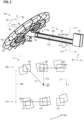
- FIG. 2 illustrates aspects with respect to the scan unit 100.
- FIG. 2 is a perspective view of an example structural implementation of the scan unit 100.
- the scan unit 100 could be fabricated from Silicon, e.g., using MEMS techniques and/or micromachining.
- the scan unit 100 includes a mirror 150.
- the mirror 150 has a reflective front side as a reflective area (obstructed from view in FIG. 2 ); as well as an opposite backside 152.
- the front side may have an integrated dispersive grating, to steer light according to its wavelength.
- the mirror 150 has a backside structure including fins and cavities - which is generally optional. Thereby, the mass moment of inertia of the mirror 150 can be tailored by appropriate geometrical implementation of the backside structure.
- the eigenfrequencies of the various motional degrees of freedom of the elastic mount 111 - including torsion and transversal deflection - can thereby be adjusted.
- torsion springs 601-603, 611-613 (the torsion springs are partly obstructed from view in the perspective of FIG. 2 ) of the elastic mount 111 extend away from the backside 152 of the mirror, towards the base 141 (the elastic coupling 400 is not illustrated in FIG. 2 ). All torsion springs 601-603, 611-613 extend along the z-axis; a longitudinal center axis 119 is illustrated.
- a spacer 142 is attached to the backside 152 of the mirror and provides a coupling between the mirror 150 and the elastic mount 111.
- the mirror spring(s) of the elastic mount 111 can extend in planes coincident with or parallel to the plane of the reflective area of the mirror 150.
- the elastic mount 111 extends away from a center of the backside 152 of the mirror 150. Thereby, an imbalance is avoided when providing a torsion 502 of the elastic mount (compare inset of FIG. 2 which is a cross-sectional view along the line A - A).
- the torsion springs 601-603, 611-613 are grouped into two (logical) sets 600, 610: the set 600 includes the torsion springs 601-603 that are arranged in a plane 691 (extending along the x-axis and the z-axis) and a set 610 includes the torsion springs 611-613 that are arranged in a plane 692 (extending along the x-axis and the z-axis, but offset to the plane 691).
- each set 600, 610 includes three respective torsion springs 601-603, 611-613, in other examples, each set may include more than three torsion springs, e.g., each set may include four, five or six torsion springs.
- the torsion spring 601-603 of the set 600 and the torsion springs 611-613 of the set 610 are configured alike, but arranged offset from each other.
- different sets may not be configured alike.
- the torsion 502 results in a twist of the torsion springs 601-603, 611-613 around the center axis 119 - which, therefore, is coincident with the respective torsion axis 501. Because all torsion spring 601-603, 611-613 are coupled to the common base 141, they implement a coherent torsion 502 and form the springs of a common mass-spring system.
- the torsion axis 501 is arranged in between the plane 691 and the plane 692.
- the center axis 119 may be offset from the torsion axis 501.
- the torsion axis 501 can be offset from the center axis 119 by using different geometrical parameters for the torsion springs 601-603, 611-613.
- the torsion 502 In addition to the twist of the torsion springs 601-603, 611-613 around the torsion axis 501, the torsion 502 also results in dynamic deformation of each individual torsion spring 601-603, 611-613. Therefore, while in the rest position (full line in the inset of FIG. 2 ), the torsion springs 601-603, 611-613 have a square cross-sectional area, the cross-sectional area is deformed upon deflection.
- the dynamic deformation depends on a distance 511, 512 of each torsion spring 601-603, 611-613 to the torsion axis 501: for example, the dynamic deformation is smaller for the center torsion springs 602, 612 which have a shorter distance 512 to the torsion axis 501 if compared to the outer torsion springs 601, 603, 611, 613 that have a larger distance 511 to the torsion axis 501. According to various examples described herein, it becomes possible to tailor the dynamics of the elastic mount 111; along with the dynamic deformation of the various torsion springs 601-603, 611-613.
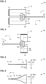
- FIGs. 3 - 6 illustrate aspects with respect to the actuator 172.
- the elastic mount 111 is schematically illustrated, without resolving the individual torsion springs 601-603, 611-613 of the elastic mount 111, for sake of simplicity.
- the mirror is not illustrated, but could be attached to the spacer 142 in an out-of-plane arrangement (cf. FIG. 2 ) or an in-plane arrangement.
- the actuator 172 is coupled with the base 141 next to the respective end 111A of the elastic mount 111 - while the mirror is coupled to the opposite end 111B of the elastic mount 111 (also cf. FIGs. 1 and 2 ).
- the actuator 172 is implemented by a pair of bending piezoelectric actuators 310, 320.
- the bending piezoelectric actuators 310, 320 are coupled to interface elements 146 of the base 141 of the scan unit 100.
- an adhesive may be used to couple the bending piezoelectric actuators 310, 320 to the interface elements.
- two interface elements 146 - roughly shaped as wings of the base 141 - are arranged on opposite sides of the base 141.
- one of the interface elements 146 may be fixed, e.g., with respect to a reference coordinate system defined by the housing, etc..
- FIG. 5 is a side view of the bending piezoelectric actuators 310, 320.
- FIG. 5 illustrates the bending piezoelectric actuators 310, 320 in their rest position, e.g., if there is the control signal 179 having zero level being applied.
- FIG. 6 illustrates the reversal states of the deflection 399 of the bending piezoelectric actuators 310, 320.
- the fixed end 311, 321 forms a non-elastic coupling between the bending piezoelectric actuators 310, 320 and a housing of the scan system 90 (not illustrated in FIGs. 3 - 5 ).
- the bending piezoelectric actuators 310, 320 are aligned essentially in parallel with each other. Also, a head-to-tail arrangement of the bending piezoelectric actuators 310, 320 would be possible; or, generally, an arbitrary orientation in between the longitudinal axis 319, 329.
- the example of FIG. 4 generally corresponds to the example of FIG. 3 , wherein, in FIG. 4 , another arrangement of the bending piezoelectric actuators 310, 320 with respect to the elastic mount 111 is illustrated (rotated by 90° in their plane if compared to FIG. 3 ).
- the bending piezoelectric actuators 310, 320 are bent along the longitudinal axis 319.
- the bending piezoelectric actuators 310, 320 typically include a layer stack of different materials (not illustrated in FIG. 3 - 5 ). Thereby, a movable end 315, 325 of the bending piezoelectric actuators 310, 320 is displaced with respect to a fixed end 311, 321 perpendicular to the respective longitudinal axis 319, 329 (in the example of FIG. 3 , this deflection is oriented perpendicular to the drawing plane).
- This deflection 399 of the bending piezoelectric actuators 310, 320 is illustrated in FIG. 5 .
- the peak-to-peak stroke length 399A is illustrated.
- the bending piezoelectric actuators 310, 320 perform a quasi-linear motion along the y-direction.
- actuators for example a magnetic drive.
- FIGs. 7-9 illustrate aspects with respect to deflecting the base 141.
- FIGs. 7 - 9 are cross-sectional views along the line B-B in FIG. 3 or FIG. 4 .
- the elastic mount 111 can be actuated.
- the base 141 can be deflected periodically at one or more frequencies which resonantly or semi-resonantly excite a torsional eigenmode of the mass-spring system formed by the elastic mount 111 and the mirror 150.
- the base 141 can be deflected periodically at one or more frequencies which resonantly or semi-resonantly excite a transversal eigenmode of the mass-spring system (flexure eigenmode).
- FIG. 7 illustrates the bending piezoelectric actuators 310, 320 in their rest position.
- the base 141 is not deflected.
- FIG. 8 illustrates an out-of-phase deflection of the bending piezoelectric actuators 310, 320 which result in a rotational motion of the base 141 (the axis of rotation 550 is oriented perpendicular in the drawing plane of FIG. 8 ).
- Such a rotational motion of the base 141 can effectively couple energy into the torsional eigenmode of the mass-spring system formed by the mirror 150 and the elastic mount 111 which can thereby be excited/driven.
- FIG. 9 illustrates an in-phase deflection of the bending piezoelectric actuators 310, 320 which results in a translational motion of the base 141 (the axis of motion is oriented up-down in the drawing plane of FIG. 9 ).
- Such a translational motion of the base 141 can effectively couple energy into the transversal eigenmode of the mass-spring system formed by the elastic mount 111 and the mirror 150.
- the force exerted by the bending piezoelectric actuators 310, 320 to move the base 141 is transferred via the interface elements 146.
- elasticity of the coupling 400 between the interface elements 146 and the base 141 is provided for (cf. FIG. 8 ).
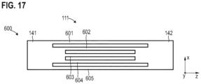
- FIGs. 10 - 15 illustrate aspects with respect to the implementation of the elastic mount 111.
- FIGs. 10 - 15 for sake of simplicity, only the torsion spring 601-604 of the set 600 are illustrated; is already discussed above, it would be possible that the set 610 is configured in the same manner as the set 600.
- FIGs. 10 - 15 illustrate different implementations of the elastic mount 111, wherein one or more geometrical parameters of the torsion springs 601-604 of the set 600 are varied from implementation to implementation. It is possible to combine the examples of FIGs. 10 - 15 to form further examples.
- the geometrical parameters that may be tuned include: the length of the torsional springs along the z-axis; the cross-sectional area of the cross-section in the xy-plane; a shape of this cross-section; a width along the x-axis; and a width along the y-axis.
- FIG. 10 the implementation of the elastic mount 111 according to FIG. 2 is illustrated: i.e., there is a count of three torsion spring 601-603.
- the torsion springs 601-603 all have the same width 651-653. Also, a gap width 671, 672 between neighboring torsion springs 601-603 is fixed. Furthermore, all torsion spring 601-603 have the same length 661-663.
- the torsion springs 601, 603 are outer torsion springs, because they enclose the inner torsion spring 602 (in the zx-plane).
- FIG. 11 illustrates another implementation of the elastic mount 111.
- the implementation of FIG. 11 generally corresponds to the implementation of FIG. 10 : again, all torsion spring 601-604 have the same width, the gap width 671-673 is fixed, and all torsion springs 601-604 have the same length 661-664. However, the count of torsion springs 601-604 of the set 600 is increased from three (in FIG. 10 ) to four in FIG. 11 .
- the torsion springs 601, 604 are outer torsion springs, because they enclose the inner torsion springs 602, 603.
- torsion springs By providing a larger count of torsion springs, there is generally a tendency that the overall spring stiffness of the elastic mount 111 increases. Then, the eigenfrequency of the torsion eigenmode also increases - which can be desirable in various applications. At the same time, the dynamic deformation of the individual torsion springs is not affected significantly; which helps to avoid damage to the material. A higher stiffness may result in a larger power required to drive the torsional eigenmode.
- FIG. 12 illustrates another implementation of the elastic mount 111.
- the implementation of FIG. 12 generally corresponds to the implementation of FIG. 11 in that there is a count of four torsion springs that are shaped like.
- the inter-spring gap width 671-673 is not fixed:
- the gap width 671-673 between the two inner torsion springs 602, 603 is larger than the gap width 671, 673 between a respective one of the inner torsion springs 602, 603 and a respective one of the outer torsion springs 601, 604.
- a somewhat inverted scenario with varying inter-torsion spring gap width 671-673 is illustrated in FIG. 13 : here, the gap width 672 is smaller than the gap widths 671, 673.
- FIG. 14 illustrates another implementation of the elastic mount 111.
- the implementation of FIG. 14 generally corresponds to the implementation of FIG. 11 : again, all four torsion springs 601-604 have the same gap width 651-654 (albeit generally the gap width 651-653 may be varied across the set 600 and/or the set 610).
- the inner torsion springs 602, 603 have a shorter length 662, 663 if compared to the length 661, 664 of the outer torsion springs 601, 604.
- the length of one or more inner torsion springs is in the range of 70% to 95% of the length of the outer torsion springs of a given set. This may correspond with the following finding: As a general rule, it would be possible that a ratio between ( i ) the length 662, 663 of the inner torsion spring(s) and (ii) the length 661, 664 of the outer torsion springs corresponds to a ratio between ( i ) the distance 512 between the inner torsion spring(s) and the torsion axis 501 and (ii) the distance 511 between the outer torsion springs and the torsion axis 501.
- FIG. 15 illustrates another implementation of the elastic mount 111.
- the implementation of FIG. 15 includes a count of three torsion spring 601-603 that have varying widths 651-653.
- the width 652 of the inner torsion spring 602 is larger than the width 651, 653 of the outer torsion springs 601, 603.
- the cross-sectional area of the torsion spring 602 is increased if compared to the cross-sectional area of the outer torsion springs 601, 603.
- various geometrical parameters of the torsion springs of a given set can be varied, the geometrical parameters being selected from the following group: the length; a width; a shape of a cross section; and scenario of a cross-section.
- this shape can be varied from torsion spring to torsion spring.
- the elastic deformation can be tailored, e.g., by rounding off edges.
- FIG. 16 illustrates frequency responses 701-703: the frequency response 701 is degressive, due to non-linear dynamics of the underlying mass-spring system; the frequency response 702 is progressive, due to non-linear dynamics of the underlying mass-spring system; while the frequency response 703 has a well-defined peak, because of linear dynamics of the underlying mass-spring system.
- the frequency responses 701-703 may be obtained for the mass-spring system formed by the (i) elastic mount 111 and ( ii ) the mirror 150, wherein the elastic mount includes two or more sets of torsion springs 601-603, 611-613, e.g., according to the examples described above.
- the frequency responses 701-703 may be obtained if a torsional eigenmode of a mass-spring system comprising one or more torsion springs and a mirror is resonantly driven.
- the control device 171 may output an appropriate control signal 179 to the actuator 172 to resonantly drive the torsional eigenmode of the mass-spring system formed by the elastic mount 111 and the mirror 150, by rotating the base 141.
- Tailoring the frequency response can correspond to selecting between the degressive frequency response 701, the progressive frequency response 702, and the harmonic frequency response 703.
- a harmonic frequency response 703 can be selected. To do so, one or more geometrical parameters of the torsion springs, the length of the torsion springs, the inter-torsion spring gap width, and/or the count of torsion springs can be varied.
- the harmonic frequency response 703 can be obtained by a parallel connection of at least one first torsion spring and at least one second torsion spring between a base and a mirror, wherein a first mass-spring system formed by ( i ) the mirror and ( ii ) the at least first torsion spring has first non-linear dynamics resulting in the progressive frequency response 702 and wherein a second mass-spring system formed by ( i ) the mirror and (ii) the at least second torsion spring has a second non-linear dynamics resulting in the degressive frequency response 701.
- examples without the first set and the second set as defined in claim 1 are not covered by the subject-matter of the claims. For example, referring to the example of FIG. 2 and FIG.
- the inner torsion springs 602, 612 form, together with the mirror 150, a first mass-spring system that has first non-linear dynamics resulting in the progressive frequency response 702; while the outer torsion springs 601, 603, 611, 613 form, together with the mirror 150, a second mass-spring system that has second non-linear dynamics resulting in the degressive frequency response 701.
- the parallel coupling of the first and second mass-spring systems result in an overall mass-spring system formed by the elastic coupling that has the harmonic frequency response 703.
- harmonic frequency responses may be obtained, by reducing non-linear contributions of the dynamics of the mass-spring system formed by the elastic mount and a mirror.
- the frequency may not change with amplitude and various amplitudes can be implemented at each frequency. Thereby, if two sequentially arranged scan units 100 are used for 2-D scanning, the mirrors of the two scan units 100 can be driven at different amplitudes at the same frequency - which provides for flexibility in the scanning pattern.
- the closed-loop control can be implemented with less complexity. For example, amplitude sweeps can be easily implemented.
- a set includes a count of three or four torsion springs, it would also be possible to include even more torsion springs per set (cf. FIG. 15 where there are five torsion springs 601-605 per set).
- two elastic mounts as described above are serially coupled (cf. FIG. 18 , where two exemplary elastic mounts 111-1 and 111-2 are serially coupled; the various elastic mounts as described herein could be serially coupled in other examples).
- the stiffness against flexure is increased; while the torsion stiffness remains essentially unchanged.
- Two or more sets of parallel torsion springs can be coupled in the intermediate part 149, by a respective spacer 142 (not shown in FIG. 18 ).
Landscapes
- Physics & Mathematics (AREA)
- General Physics & Mathematics (AREA)
- Optics & Photonics (AREA)
- Mechanical Light Control Or Optical Switches (AREA)
- Micromachines (AREA)
- Mechanical Optical Scanning Systems (AREA)
Claims (8)
- Scaneinheit (100), umfassend:- eine Basis (141);- einen Spiegel (150) zum Lenken von Licht (180),
dadurch gekennzeichnet, dass sie ferner Folgendes umfasst- einen ersten Satz (600), der mindestens drei Torsionsfedern (601-605) umfasst, die sich entlang einer Achse (z, 119) zwischen der Basis (141) und dem Spiegel (150) in einer ersten Ebene (691) erstrecken, und- einen zweiten Satz (610), der mindestens drei Torsionsfedern (611-613) umfasst, die sich entlang der Achse (z, 119) zwischen der Basis (141) und dem Spiegel (150) in einer zweiten Ebene (692) erstrecken, die von der ersten Ebene (691) versetzt und parallel dazu ist. - Scaneinheit (100) nach Anspruch 1,
wobei mindestens ein geometrischer Parameter der mindestens drei Torsionsfedern (601-605) des ersten Satzes (600) über den ersten Satz (600) variiert, wobei der mindestens eine geometrische Parameter ausgewählt ist aus einer Gruppe, die Folgendes umfasst: eine Länge (661-664); eine Fläche eines Querschnitts senkrecht zu der Achse (z, 119); eine Form des Querschnitts; eine Breite (651-654) senkrecht zu der Achse (z, 119). - Scaneinheit (100) nach Anspruch 1 oder 2,
wobei eine erste Länge (662, 663) mindestens einer inneren Torsionsfeder (602, 603) des ersten Satzes (600) im Bereich von 70 % bis 95 % einer zweiten Länge (661, 664) äußerer Torsionsfedern (601, 603, 604) des ersten Satzes (600) liegt. - Scaneinheit (100) nach einem der vorhergehenden Ansprüche,
wobei eine Spaltbreite (671-673) zwischen angrenzenden Torsionsfedern (601-603, 611-613) senkrecht zu der Achse (z, 119) über den ersten Satz (600) variiert. - Scaneinheit (100) nach einem der vorhergehenden Ansprüche,
wobei die mindestens drei Torsionsfedern (601-605) des ersten Satzes (600) auf die mindestens drei Torsionsfedern (611-613) des zweiten Satzes (610) durch eine globale translatorische Verschiebung (699) entlang einer weiteren Achse (y) senkrecht zu der ersten Ebene (691) und der zweiten Ebene (692) abgebildet werden können. - Scaneinheit (100) nach einem der vorhergehenden Ansprüche,
wobei die mindestens drei Torsionsfedern (601-605) des ersten Satzes (600) und die mindestens drei Torsionsfedern (611-613) des zweiten Satzes (610) dazu ausgelegt sind, sich um eine gemeinsame Torsionsachse (501) zu verdrehen, die zwischen der ersten Ebene (691) und der zweiten Ebene (692) angeordnet ist. - Scaneinheit (100) nach einem der vorhergehenden Ansprüche,wobei jeder des ersten Satzes (600) und des zweiten Satzes (610) äußere Torsionsfedern (601, 603, 604, 611, 613, 614) und eine oder mehrere innere Torsionsfedern (602, 603, 612, 613), die zwischen den jeweiligen äußeren Torsionsfedern (601, 603, 604, 611, 613, 614) angeordnet sind, umfasst,wobei ein erstes Masse-Feder-System, das durch (i) den Spiegel (150) und (ii) die äußeren Torsionsfedern des ersten Satzes (600) und des zweiten Satzes (610) gebildet ist, eine erste nicht-lineare Dynamik aufweist,wobei ein zweites Masse-Feder-System, das durch (i) den Spiegel (150) und die eine oder mehreren inneren Torsionsfedern (601-605) des ersten Satzes (600) und des zweiten Satzes (610) gebildet ist, eine zweite nicht-lineare Dynamik aufweist,wobei eine erste der ersten nicht-linearen Dynamik und der zweiten nicht-linearen Dynamik in einem ansteigenden Frequenzgang (702) resultiert,wobei eine zweite der ersten nicht-linearen Dynamik und der zweiten nicht-linearen Dynamik in einem absteigenden Frequenzgang (701) resultiert.
- System (90), umfassend:- die Scaneinheit (100) nach einem der vorhergehenden Ansprüche, und- eine Steuervorrichtung (171), die dazu ausgelegt ist, einen Aktuator (172) zu betätigen, um eine resonante Torsionseigenmode (502) eines Masse-Feder-Systems anzutreiben, das durch (i) den Spiegel (150) und (ii) die mindestens drei Torsionsfedern (601-605) des ersten Satzes (600) und die mindestens drei Torsionsfedern des zweiten Satzes (610) gebildet ist.
Applications Claiming Priority (2)
| Application Number | Priority Date | Filing Date | Title |
|---|---|---|---|
| SE1830222 | 2018-07-26 | ||
| PCT/EP2019/069779 WO2020020876A1 (en) | 2018-07-26 | 2019-07-23 | Reduced nonlinearities for resonant deflection of a scanning mirror |
Publications (2)
| Publication Number | Publication Date |
|---|---|
| EP3841423A1 EP3841423A1 (de) | 2021-06-30 |
| EP3841423B1 true EP3841423B1 (de) | 2023-12-20 |
Family
ID=67439213
Family Applications (1)
| Application Number | Title | Priority Date | Filing Date |
|---|---|---|---|
| EP19744674.3A Active EP3841423B1 (de) | 2018-07-26 | 2019-07-23 | Verringerte nichtlinearitäten für die resonante ablenkung eines abtastspiegels |
Country Status (3)
| Country | Link |
|---|---|
| US (1) | US20210405348A1 (de) |
| EP (1) | EP3841423B1 (de) |
| WO (1) | WO2020020876A1 (de) |
Families Citing this family (1)
| Publication number | Priority date | Publication date | Assignee | Title |
|---|---|---|---|---|
| WO2025240163A1 (en) * | 2024-05-14 | 2025-11-20 | Voyant Photonics, Inc. | Hybrid two-dimensional steering lidar |
Family Cites Families (11)
| Publication number | Priority date | Publication date | Assignee | Title |
|---|---|---|---|---|
| US8729770B1 (en) | 2003-12-02 | 2014-05-20 | Adriatic Research Institute | MEMS actuators with combined force and bi-directional rotation |
| DE102007001516B3 (de) * | 2007-01-10 | 2008-04-30 | Fraunhofer-Gesellschaft zur Förderung der angewandten Forschung e.V. | Mikromechanisches Bauelement mit einstellbarer Resonanzfrequenz durch Geometrieänderung und Verfahren zum Betreiben desselben |
| EP2208103B1 (de) | 2007-10-05 | 2013-02-13 | Innoluce B.V. | Mems-abtastmikrospiegel |
| DE102008059634B4 (de) | 2008-11-28 | 2012-12-13 | Fraunhofer-Gesellschaft zur Förderung der angewandten Forschung e.V. | Mikromechanischer Aktuator mit elektrostatischem Kamm-Antrieb |
| DE102009026502B4 (de) * | 2009-05-27 | 2017-03-16 | Robert Bosch Gmbh | Mikromechanisches Bauelement |
| US9158108B2 (en) * | 2010-07-29 | 2015-10-13 | Nec Corporation | Optical scanning device and image display device |
| US10730742B2 (en) * | 2012-01-24 | 2020-08-04 | Pioneer Corporation | Actuator with plurality of torsion bars having varying spring constant |
| US10114212B2 (en) * | 2012-05-29 | 2018-10-30 | Kabushiki Kaisha Toyota Chuo Kenkyusho | Deflector |
| WO2018055513A2 (en) | 2016-09-20 | 2018-03-29 | Innoviz Technologies Ltd. | Methods circuits devices assemblies systems and functionally associated machine executable code for light detection and ranging based scanning |
| DE102016011647A1 (de) | 2016-09-26 | 2018-03-29 | Blickfeld GmbH | Anregung von Fasern mit Biegepiezoaktuatoren |
| DE102016013227A1 (de) | 2016-11-07 | 2018-05-09 | Blickfeld GmbH | Faser-Scanner mit mindestens zwei Fasern |
-
2019
- 2019-07-23 WO PCT/EP2019/069779 patent/WO2020020876A1/en not_active Ceased
- 2019-07-23 EP EP19744674.3A patent/EP3841423B1/de active Active
- 2019-07-23 US US17/289,670 patent/US20210405348A1/en not_active Abandoned
Also Published As
| Publication number | Publication date |
|---|---|
| WO2020020876A1 (en) | 2020-01-30 |
| EP3841423A1 (de) | 2021-06-30 |
| US20210405348A1 (en) | 2021-12-30 |
Similar Documents
| Publication | Publication Date | Title |
|---|---|---|
| US11526000B2 (en) | Two-axis MEMS mirror with separated drives | |
| EP2902358B1 (de) | Elektrostatisch angetriebene mems-vorrichtung, insbesondere drehbarer mikrospiegel | |
| US7355774B2 (en) | Optical deflector and optical apparatus using the same | |
| CN110312944B (zh) | 用于光扫描仪的mems扫描模块 | |
| JP4984117B2 (ja) | 2次元光スキャナ、それを用いた光学装置および2次元光スキャナの製造方法 | |
| EP2808719A1 (de) | Optischer Deflektor mit getrennten piezoelektrischen Abschnitten auf piezoelektrischen Aktuatoren und deren Entwurfsverfahren | |
| WO2006131916A1 (en) | Bouncing mode operated scanning micro-mirror | |
| CN104101981B (zh) | 用于偏转电磁辐射的微致动器装置 | |
| US12436380B2 (en) | Optical scanning device and control method thereof | |
| US8270057B2 (en) | Oscillator device, optical deflecting device and method of controlling the same | |
| US8238011B1 (en) | MEMS device with off-axis actuator | |
| US8072664B1 (en) | Biaxial scanning mirror having resonant frequency adjustment | |
| EP3841423B1 (de) | Verringerte nichtlinearitäten für die resonante ablenkung eines abtastspiegels | |
| US9097894B2 (en) | Optical deflector including four coupling bars between support body and frame | |
| US10838198B2 (en) | Actuator and light scanning apparatus | |
| JP5554895B2 (ja) | 揺動構造体、及び揺動構造体を用いた揺動体装置 | |
| EP2028523A1 (de) | Oszillierende Vorrichtung, Lichtdeflektor und Bilderzeugungsvorrichtung, die diesen verwendet | |
| JP2007206480A (ja) | 光走査素子 | |
| US20220404615A1 (en) | Optical scanning device and control method thereof | |
| US20210405349A1 (en) | Actuation of a scanning mirror using an elastic coupling | |
| US8581470B2 (en) | Electrode comb, micromechanical component, and method for producing an electrode comb or a micromechanical component | |
| US11815627B2 (en) | Mirror assembly for light steering with reduced finger thickness | |
| JP2022032538A (ja) | 光偏向装置、光走査装置及び光走査式測距装置 | |
| JP6369357B2 (ja) | 走査装置 | |
| US12306303B2 (en) | Mirror assembly for light steering |
Legal Events
| Date | Code | Title | Description |
|---|---|---|---|
| STAA | Information on the status of an ep patent application or granted ep patent |
Free format text: STATUS: UNKNOWN |
|
| STAA | Information on the status of an ep patent application or granted ep patent |
Free format text: STATUS: THE INTERNATIONAL PUBLICATION HAS BEEN MADE |
|
| PUAI | Public reference made under article 153(3) epc to a published international application that has entered the european phase |
Free format text: ORIGINAL CODE: 0009012 |
|
| STAA | Information on the status of an ep patent application or granted ep patent |
Free format text: STATUS: REQUEST FOR EXAMINATION WAS MADE |
|
| 17P | Request for examination filed |
Effective date: 20210430 |
|
| AK | Designated contracting states |
Kind code of ref document: A1 Designated state(s): AL AT BE BG CH CY CZ DE DK EE ES FI FR GB GR HR HU IE IS IT LI LT LU LV MC MK MT NL NO PL PT RO RS SE SI SK SM TR |
|
| DAV | Request for validation of the european patent (deleted) | ||
| DAX | Request for extension of the european patent (deleted) | ||
| GRAP | Despatch of communication of intention to grant a patent |
Free format text: ORIGINAL CODE: EPIDOSNIGR1 |
|
| STAA | Information on the status of an ep patent application or granted ep patent |
Free format text: STATUS: GRANT OF PATENT IS INTENDED |
|
| RIC1 | Information provided on ipc code assigned before grant |
Ipc: G02B 26/10 20060101ALI20230316BHEP Ipc: G02B 26/08 20060101AFI20230316BHEP |
|
| INTG | Intention to grant announced |
Effective date: 20230413 |
|
| GRAS | Grant fee paid |
Free format text: ORIGINAL CODE: EPIDOSNIGR3 |
|
| GRAA | (expected) grant |
Free format text: ORIGINAL CODE: 0009210 |
|
| STAA | Information on the status of an ep patent application or granted ep patent |
Free format text: STATUS: THE PATENT HAS BEEN GRANTED |
|
| AK | Designated contracting states |
Kind code of ref document: B1 Designated state(s): AL AT BE BG CH CY CZ DE DK EE ES FI FR GB GR HR HU IE IS IT LI LT LU LV MC MK MT NL NO PL PT RO RS SE SI SK SM TR |
|
| REG | Reference to a national code |
Ref country code: GB Ref legal event code: FG4D |
|
| REG | Reference to a national code |
Ref country code: CH Ref legal event code: EP |
|
| REG | Reference to a national code |
Ref country code: DE Ref legal event code: R096 Ref document number: 602019043597 Country of ref document: DE |
|
| REG | Reference to a national code |
Ref country code: IE Ref legal event code: FG4D |
|
| PG25 | Lapsed in a contracting state [announced via postgrant information from national office to epo] |
Ref country code: GR Free format text: LAPSE BECAUSE OF FAILURE TO SUBMIT A TRANSLATION OF THE DESCRIPTION OR TO PAY THE FEE WITHIN THE PRESCRIBED TIME-LIMIT Effective date: 20240321 |
|
| REG | Reference to a national code |
Ref country code: LT Ref legal event code: MG9D |
|
| PG25 | Lapsed in a contracting state [announced via postgrant information from national office to epo] |
Ref country code: LT Free format text: LAPSE BECAUSE OF FAILURE TO SUBMIT A TRANSLATION OF THE DESCRIPTION OR TO PAY THE FEE WITHIN THE PRESCRIBED TIME-LIMIT Effective date: 20231220 |
|
| REG | Reference to a national code |
Ref country code: NL Ref legal event code: MP Effective date: 20231220 |
|
| PG25 | Lapsed in a contracting state [announced via postgrant information from national office to epo] |
Ref country code: ES Free format text: LAPSE BECAUSE OF FAILURE TO SUBMIT A TRANSLATION OF THE DESCRIPTION OR TO PAY THE FEE WITHIN THE PRESCRIBED TIME-LIMIT Effective date: 20231220 |
|
| PG25 | Lapsed in a contracting state [announced via postgrant information from national office to epo] |
Ref country code: LT Free format text: LAPSE BECAUSE OF FAILURE TO SUBMIT A TRANSLATION OF THE DESCRIPTION OR TO PAY THE FEE WITHIN THE PRESCRIBED TIME-LIMIT Effective date: 20231220 Ref country code: GR Free format text: LAPSE BECAUSE OF FAILURE TO SUBMIT A TRANSLATION OF THE DESCRIPTION OR TO PAY THE FEE WITHIN THE PRESCRIBED TIME-LIMIT Effective date: 20240321 Ref country code: FI Free format text: LAPSE BECAUSE OF FAILURE TO SUBMIT A TRANSLATION OF THE DESCRIPTION OR TO PAY THE FEE WITHIN THE PRESCRIBED TIME-LIMIT Effective date: 20231220 Ref country code: ES Free format text: LAPSE BECAUSE OF FAILURE TO SUBMIT A TRANSLATION OF THE DESCRIPTION OR TO PAY THE FEE WITHIN THE PRESCRIBED TIME-LIMIT Effective date: 20231220 Ref country code: BG Free format text: LAPSE BECAUSE OF FAILURE TO SUBMIT A TRANSLATION OF THE DESCRIPTION OR TO PAY THE FEE WITHIN THE PRESCRIBED TIME-LIMIT Effective date: 20240320 |
|
| REG | Reference to a national code |
Ref country code: AT Ref legal event code: MK05 Ref document number: 1642950 Country of ref document: AT Kind code of ref document: T Effective date: 20231220 |
|
| PG25 | Lapsed in a contracting state [announced via postgrant information from national office to epo] |
Ref country code: NL Free format text: LAPSE BECAUSE OF FAILURE TO SUBMIT A TRANSLATION OF THE DESCRIPTION OR TO PAY THE FEE WITHIN THE PRESCRIBED TIME-LIMIT Effective date: 20231220 |
|
| PG25 | Lapsed in a contracting state [announced via postgrant information from national office to epo] |
Ref country code: SE Free format text: LAPSE BECAUSE OF FAILURE TO SUBMIT A TRANSLATION OF THE DESCRIPTION OR TO PAY THE FEE WITHIN THE PRESCRIBED TIME-LIMIT Effective date: 20231220 Ref country code: RS Free format text: LAPSE BECAUSE OF FAILURE TO SUBMIT A TRANSLATION OF THE DESCRIPTION OR TO PAY THE FEE WITHIN THE PRESCRIBED TIME-LIMIT Effective date: 20231220 Ref country code: NO Free format text: LAPSE BECAUSE OF FAILURE TO SUBMIT A TRANSLATION OF THE DESCRIPTION OR TO PAY THE FEE WITHIN THE PRESCRIBED TIME-LIMIT Effective date: 20240320 Ref country code: NL Free format text: LAPSE BECAUSE OF FAILURE TO SUBMIT A TRANSLATION OF THE DESCRIPTION OR TO PAY THE FEE WITHIN THE PRESCRIBED TIME-LIMIT Effective date: 20231220 Ref country code: LV Free format text: LAPSE BECAUSE OF FAILURE TO SUBMIT A TRANSLATION OF THE DESCRIPTION OR TO PAY THE FEE WITHIN THE PRESCRIBED TIME-LIMIT Effective date: 20231220 Ref country code: HR Free format text: LAPSE BECAUSE OF FAILURE TO SUBMIT A TRANSLATION OF THE DESCRIPTION OR TO PAY THE FEE WITHIN THE PRESCRIBED TIME-LIMIT Effective date: 20231220 |
|
| PG25 | Lapsed in a contracting state [announced via postgrant information from national office to epo] |
Ref country code: IS Free format text: LAPSE BECAUSE OF FAILURE TO SUBMIT A TRANSLATION OF THE DESCRIPTION OR TO PAY THE FEE WITHIN THE PRESCRIBED TIME-LIMIT Effective date: 20240420 |
|
| PG25 | Lapsed in a contracting state [announced via postgrant information from national office to epo] |
Ref country code: CZ Free format text: LAPSE BECAUSE OF FAILURE TO SUBMIT A TRANSLATION OF THE DESCRIPTION OR TO PAY THE FEE WITHIN THE PRESCRIBED TIME-LIMIT Effective date: 20231220 Ref country code: AT Free format text: LAPSE BECAUSE OF FAILURE TO SUBMIT A TRANSLATION OF THE DESCRIPTION OR TO PAY THE FEE WITHIN THE PRESCRIBED TIME-LIMIT Effective date: 20231220 |
|
| PG25 | Lapsed in a contracting state [announced via postgrant information from national office to epo] |
Ref country code: SK Free format text: LAPSE BECAUSE OF FAILURE TO SUBMIT A TRANSLATION OF THE DESCRIPTION OR TO PAY THE FEE WITHIN THE PRESCRIBED TIME-LIMIT Effective date: 20231220 |
|
| PG25 | Lapsed in a contracting state [announced via postgrant information from national office to epo] |
Ref country code: SM Free format text: LAPSE BECAUSE OF FAILURE TO SUBMIT A TRANSLATION OF THE DESCRIPTION OR TO PAY THE FEE WITHIN THE PRESCRIBED TIME-LIMIT Effective date: 20231220 Ref country code: SK Free format text: LAPSE BECAUSE OF FAILURE TO SUBMIT A TRANSLATION OF THE DESCRIPTION OR TO PAY THE FEE WITHIN THE PRESCRIBED TIME-LIMIT Effective date: 20231220 Ref country code: RO Free format text: LAPSE BECAUSE OF FAILURE TO SUBMIT A TRANSLATION OF THE DESCRIPTION OR TO PAY THE FEE WITHIN THE PRESCRIBED TIME-LIMIT Effective date: 20231220 Ref country code: IT Free format text: LAPSE BECAUSE OF FAILURE TO SUBMIT A TRANSLATION OF THE DESCRIPTION OR TO PAY THE FEE WITHIN THE PRESCRIBED TIME-LIMIT Effective date: 20231220 Ref country code: IS Free format text: LAPSE BECAUSE OF FAILURE TO SUBMIT A TRANSLATION OF THE DESCRIPTION OR TO PAY THE FEE WITHIN THE PRESCRIBED TIME-LIMIT Effective date: 20240420 Ref country code: EE Free format text: LAPSE BECAUSE OF FAILURE TO SUBMIT A TRANSLATION OF THE DESCRIPTION OR TO PAY THE FEE WITHIN THE PRESCRIBED TIME-LIMIT Effective date: 20231220 Ref country code: CZ Free format text: LAPSE BECAUSE OF FAILURE TO SUBMIT A TRANSLATION OF THE DESCRIPTION OR TO PAY THE FEE WITHIN THE PRESCRIBED TIME-LIMIT Effective date: 20231220 Ref country code: AT Free format text: LAPSE BECAUSE OF FAILURE TO SUBMIT A TRANSLATION OF THE DESCRIPTION OR TO PAY THE FEE WITHIN THE PRESCRIBED TIME-LIMIT Effective date: 20231220 |
|
| PG25 | Lapsed in a contracting state [announced via postgrant information from national office to epo] |
Ref country code: PT Free format text: LAPSE BECAUSE OF FAILURE TO SUBMIT A TRANSLATION OF THE DESCRIPTION OR TO PAY THE FEE WITHIN THE PRESCRIBED TIME-LIMIT Effective date: 20240422 Ref country code: PL Free format text: LAPSE BECAUSE OF FAILURE TO SUBMIT A TRANSLATION OF THE DESCRIPTION OR TO PAY THE FEE WITHIN THE PRESCRIBED TIME-LIMIT Effective date: 20231220 |
|
| PG25 | Lapsed in a contracting state [announced via postgrant information from national office to epo] |
Ref country code: PT Free format text: LAPSE BECAUSE OF FAILURE TO SUBMIT A TRANSLATION OF THE DESCRIPTION OR TO PAY THE FEE WITHIN THE PRESCRIBED TIME-LIMIT Effective date: 20240422 Ref country code: PL Free format text: LAPSE BECAUSE OF FAILURE TO SUBMIT A TRANSLATION OF THE DESCRIPTION OR TO PAY THE FEE WITHIN THE PRESCRIBED TIME-LIMIT Effective date: 20231220 |
|
| REG | Reference to a national code |
Ref country code: DE Ref legal event code: R097 Ref document number: 602019043597 Country of ref document: DE |
|
| PG25 | Lapsed in a contracting state [announced via postgrant information from national office to epo] |
Ref country code: DK Free format text: LAPSE BECAUSE OF FAILURE TO SUBMIT A TRANSLATION OF THE DESCRIPTION OR TO PAY THE FEE WITHIN THE PRESCRIBED TIME-LIMIT Effective date: 20231220 |
|
| PLBE | No opposition filed within time limit |
Free format text: ORIGINAL CODE: 0009261 |
|
| STAA | Information on the status of an ep patent application or granted ep patent |
Free format text: STATUS: NO OPPOSITION FILED WITHIN TIME LIMIT |
|
| PG25 | Lapsed in a contracting state [announced via postgrant information from national office to epo] |
Ref country code: SI Free format text: LAPSE BECAUSE OF FAILURE TO SUBMIT A TRANSLATION OF THE DESCRIPTION OR TO PAY THE FEE WITHIN THE PRESCRIBED TIME-LIMIT Effective date: 20231220 |
|
| PG25 | Lapsed in a contracting state [announced via postgrant information from national office to epo] |
Ref country code: SI Free format text: LAPSE BECAUSE OF FAILURE TO SUBMIT A TRANSLATION OF THE DESCRIPTION OR TO PAY THE FEE WITHIN THE PRESCRIBED TIME-LIMIT Effective date: 20231220 Ref country code: DK Free format text: LAPSE BECAUSE OF FAILURE TO SUBMIT A TRANSLATION OF THE DESCRIPTION OR TO PAY THE FEE WITHIN THE PRESCRIBED TIME-LIMIT Effective date: 20231220 |
|
| 26N | No opposition filed |
Effective date: 20240923 |
|
| REG | Reference to a national code |
Ref country code: DE Ref legal event code: R119 Ref document number: 602019043597 Country of ref document: DE |
|
| PG25 | Lapsed in a contracting state [announced via postgrant information from national office to epo] |
Ref country code: MC Free format text: LAPSE BECAUSE OF FAILURE TO SUBMIT A TRANSLATION OF THE DESCRIPTION OR TO PAY THE FEE WITHIN THE PRESCRIBED TIME-LIMIT Effective date: 20231220 |
|
| REG | Reference to a national code |
Ref country code: CH Ref legal event code: PL |
|
| PG25 | Lapsed in a contracting state [announced via postgrant information from national office to epo] |
Ref country code: LU Free format text: LAPSE BECAUSE OF NON-PAYMENT OF DUE FEES Effective date: 20240723 |
|
| GBPC | Gb: european patent ceased through non-payment of renewal fee |
Effective date: 20240723 |
|
| PG25 | Lapsed in a contracting state [announced via postgrant information from national office to epo] |
Ref country code: LU Free format text: LAPSE BECAUSE OF NON-PAYMENT OF DUE FEES Effective date: 20240723 |
|
| PG25 | Lapsed in a contracting state [announced via postgrant information from national office to epo] |
Ref country code: DE Free format text: LAPSE BECAUSE OF NON-PAYMENT OF DUE FEES Effective date: 20250201 |
|
| PG25 | Lapsed in a contracting state [announced via postgrant information from national office to epo] |
Ref country code: BE Free format text: LAPSE BECAUSE OF NON-PAYMENT OF DUE FEES Effective date: 20240731 Ref country code: CH Free format text: LAPSE BECAUSE OF NON-PAYMENT OF DUE FEES Effective date: 20240731 |
|
| PG25 | Lapsed in a contracting state [announced via postgrant information from national office to epo] |
Ref country code: FR Free format text: LAPSE BECAUSE OF NON-PAYMENT OF DUE FEES Effective date: 20240731 |
|
| PG25 | Lapsed in a contracting state [announced via postgrant information from national office to epo] |
Ref country code: GB Free format text: LAPSE BECAUSE OF NON-PAYMENT OF DUE FEES Effective date: 20240723 |
|
| REG | Reference to a national code |
Ref country code: BE Ref legal event code: MM Effective date: 20240731 |
|
| PG25 | Lapsed in a contracting state [announced via postgrant information from national office to epo] |
Ref country code: IE Free format text: LAPSE BECAUSE OF NON-PAYMENT OF DUE FEES Effective date: 20240723 |
|
| PG25 | Lapsed in a contracting state [announced via postgrant information from national office to epo] |
Ref country code: CY Free format text: LAPSE BECAUSE OF FAILURE TO SUBMIT A TRANSLATION OF THE DESCRIPTION OR TO PAY THE FEE WITHIN THE PRESCRIBED TIME-LIMIT; INVALID AB INITIO Effective date: 20190723 |
|
| PG25 | Lapsed in a contracting state [announced via postgrant information from national office to epo] |
Ref country code: HU Free format text: LAPSE BECAUSE OF FAILURE TO SUBMIT A TRANSLATION OF THE DESCRIPTION OR TO PAY THE FEE WITHIN THE PRESCRIBED TIME-LIMIT; INVALID AB INITIO Effective date: 20190723 |