EP3841439B1 - Système d'automatisation de la surveillance d'un processus critique en matière de sécurité - Google Patents
Système d'automatisation de la surveillance d'un processus critique en matière de sécurité Download PDFInfo
- Publication number
- EP3841439B1 EP3841439B1 EP19732606.9A EP19732606A EP3841439B1 EP 3841439 B1 EP3841439 B1 EP 3841439B1 EP 19732606 A EP19732606 A EP 19732606A EP 3841439 B1 EP3841439 B1 EP 3841439B1
- Authority
- EP
- European Patent Office
- Prior art keywords
- safe
- fail
- peripheral module
- platform
- automation system
- Prior art date
- Legal status (The legal status is an assumption and is not a legal conclusion. Google has not performed a legal analysis and makes no representation as to the accuracy of the status listed.)
- Active
Links
Images



Classifications
-
- G—PHYSICS
- G05—CONTROLLING; REGULATING
- G05B—CONTROL OR REGULATING SYSTEMS IN GENERAL; FUNCTIONAL ELEMENTS OF SUCH SYSTEMS; MONITORING OR TESTING ARRANGEMENTS FOR SUCH SYSTEMS OR ELEMENTS
- G05B9/00—Safety arrangements
- G05B9/02—Safety arrangements electric
-
- G—PHYSICS
- G05—CONTROLLING; REGULATING
- G05B—CONTROL OR REGULATING SYSTEMS IN GENERAL; FUNCTIONAL ELEMENTS OF SUCH SYSTEMS; MONITORING OR TESTING ARRANGEMENTS FOR SUCH SYSTEMS OR ELEMENTS
- G05B19/00—Program-control systems
- G05B19/02—Program-control systems electric
- G05B19/04—Program control other than numerical control, i.e. in sequence controllers or logic controllers
- G05B19/042—Program control other than numerical control, i.e. in sequence controllers or logic controllers using digital processors
- G05B19/0423—Input/output
- G05B19/0425—Safety, monitoring
-
- G—PHYSICS
- G07—CHECKING-DEVICES
- G07C—TIME OR ATTENDANCE REGISTERS; REGISTERING OR INDICATING THE WORKING OF MACHINES; GENERATING RANDOM NUMBERS; VOTING OR LOTTERY APPARATUS; ARRANGEMENTS, SYSTEMS OR APPARATUS FOR CHECKING NOT PROVIDED FOR ELSEWHERE
- G07C3/00—Registering or indicating the condition or the working of machines or other apparatus, other than vehicles
- G07C3/08—Registering or indicating the production of the machine either with or without registering working or idle time
-
- H—ELECTRICITY
- H04—ELECTRIC COMMUNICATION TECHNIQUE
- H04L—TRANSMISSION OF DIGITAL INFORMATION, e.g. TELEGRAPHIC COMMUNICATION
- H04L9/00—Cryptographic mechanisms or cryptographic arrangements for secret or secure communications; Network security protocols
- H04L9/08—Key distribution or management, e.g. generation, sharing or updating, of cryptographic keys or passwords
- H04L9/0861—Generation of secret information including derivation or calculation of cryptographic keys or passwords
- H04L9/0869—Generation of secret information including derivation or calculation of cryptographic keys or passwords involving random numbers or seeds
-
- G—PHYSICS
- G05—CONTROLLING; REGULATING
- G05B—CONTROL OR REGULATING SYSTEMS IN GENERAL; FUNCTIONAL ELEMENTS OF SUCH SYSTEMS; MONITORING OR TESTING ARRANGEMENTS FOR SUCH SYSTEMS OR ELEMENTS
- G05B2219/00—Program-control systems
- G05B2219/30—Nc systems
- G05B2219/36—Nc in input of data, input key till input tape
- G05B2219/36542—Cryptography, encrypt, access, authorize with key, code, password
Definitions
- the present invention relates to an automation system for monitoring a safety-critical process, a corresponding method and a monitoring device for ensuring the execution of a safety function implemented from user programs on a platform and a fail-safe peripheral module for coupling a platform, which executes user programs to implement a safety function, to a safety-critical process.
- Automation systems for monitoring a safety-critical process are used to reduce the risk posed by technical systems to people and the environment.
- safety functions are implemented that bring the technical system or the safety-critical process into a safe state in the event of danger.
- the term safety function is understood to be a safety-related control function of a machine that reduces the risk posed by the machine to an acceptable level.
- An example of a safety function is the shutdown of a machine after an emergency stop button is pressed.
- safety functions were initially implemented by individual safe components, for example in the form of safety switching devices with relay technology, which operated independently of the control system of the system to be monitored.
- safety switching devices were then logically linked to one another in order to implement more complex safety functions.
- Safety controllers are used today for even more complex tasks. Safety controllers were developed primarily from the desire to be able to program safety in a similar way to a programmable logic controller (PLC). In terms of their actual function, safety controllers therefore differ only slightly from PLC controllers. In essence, a safety controller is two individual PLC controllers that process a user program in parallel, use the same process image of the inputs/outputs and constantly synchronize with each other.
- PLC programmable logic controller
- a safety controller differs considerably from that of a PLC controller in order to implement the safety-related features.
- a safety controller therefore differs from a PLC controller in that it has two separate channels, a diverse structure with different hardware, constant testing of the inputs and outputs, constant comparison of user data, voltage and time monitoring, and safe shutdown in the event of an error or danger.
- the components involved in the safety functions - in particular the CPUs (Central Processing Unit) - must be fail-safe.
- SIL 3 Safety Integrity Level
- IEC 61508 redundant CPUs were originally used, i.e. at least two CPUs that monitor each other.
- EP 1 043 641 A2 is a fail-safe automation system that is based on a standard CPU.
- the error control measures are largely integrated into the user program and include: safety protocols, temporal program run control, logical program run and data flow control, data backup through information redundancy, diverse processing and self-tests within the process error tolerance time. Commands that cannot be implemented diversely are tested within the process error tolerance time. In addition, background tests are carried out by the CPU's operating system to detect multiple errors within the multiple error occurrence time.
- So-called Software Coded Processing takes a processor-independent approach.
- a system extended with SCP is able to reveal transient, permanent and systematic execution errors during runtime.
- interference between different programs can be detected and displayed.
- the best-known variant of SCP is so-called AN coding, i.e. an arithmetic coding in which every value of a program is multiplied by a constant A, in particular a prime number. All values and states in the system that are not a multiple of A are then considered invalid states.
- the coded program then works with coded input values, coded states and generates a coded output.
- the native and the coded program both work with the same output values, whereby the coded input values are the coded variant of the native input values. The same applies to the state and output values.
- the native and the coded program are executed and managed by a so-called diversity framework.
- the diversity framework is generated from the source code of the original safety function by enriching the source code with appropriate annotations.
- the diversity framework coordinates the parallel execution of the two programs (native and coded) and verifies error-free execution using checksums that it creates over the native and coded output values.
- the diversity framework can monitor the control flow of the safety function by integrating the data flow of the control flow check in such a way that every control flow error changes the output checksum.
- the coded operations take a lot of runtime and the code generation is time-consuming and complex, especially if signature methods are also used.
- the coded program in SPC requires more bits for storing and processing values than the native variant. If, for example, the native program uses 32-bit data types, the coded program must use at least data types that can store A times the largest possible value of a 32-bit data type. The coded program is therefore usually implemented with 64-bit data types if the native program uses 32-bit data types.
- All native operations must be replaced by corresponding coded operations, the execution of which takes more time than the native operations and requires a correspondingly complex tool chain to create.
- an automation system for monitoring a safety-critical process comprising a non-safe platform for executing user programs that implement a safety function, a fail-safe peripheral module via which the safety-critical process can be coupled to the user programs, and a monitoring device that is designed to ensure the execution of the safety function on the non-safe platform, wherein the monitoring device can be coupled to the non-safe platform via a first communication interface and the fail-safe peripheral module can be coupled to the non-safe platform via a second communication interface, and wherein the monitoring device is designed to execute at least one fail-safe service independently of the non-safe platform in order to cyclically exchange data generated by the fail-safe service with the fail-safe peripheral module according to a defined scheme, and wherein the fail-safe peripheral module is designed to, depending on the implemented safety function and on the basis of the data exchange that takes place via the non-secure platform to signal a secure state.
- This task is also solved by a corresponding procedure.
- the external components preferably implemented as dedicated hardware, work together in such a way that if the user programs on the platform are executed incorrectly, if the platform itself behaves incorrectly, or if there are errors in communication with it, the process enters a safe state.
- a monitoring device ensures that the user programs are executed, preferably by having the monitoring device work together with a safe runtime environment on the platform.
- the monitoring device can initiate the execution of the safety function independently of the platform via the fail-safe peripheral module using a separate service that is executed independently of the platform based on the "watchdog" principle, in particular by shutting down the process.
- the platform can be a software, hardware or virtual platform that serves as the basis for the development and execution of user programs based on it.
- the platform is a non-secure platform, for example a single-channel system such as a standard PC.
- the platform can also be provided in the form of cloud computing, in particular as Infrastructure as a Service (IaaS) or Platform as a Service (PaaS) .
- the platform can already include a secure runtime environment.
- non-secure means that the non-secure platform does not meet the relevant safety requirements in order to carry out a safety function on its own with the required level of inherent fault tolerance.
- the fail-safe service can implement simple data functions or operations that can be implemented reliably and fail-safely in hardware or software. Furthermore, they can be certified with little effort in accordance with the relevant safety standards, even for high safety categories. The scope of the monitoring device is therefore limited to what is absolutely necessary for the exclusive execution of at least one fail-safe service.
- the monitoring device is connected to the fail-safe peripheral module via a communication interface, which is also non-safe, i.e. a single-channel communication interface, in order to exchange data generated cyclically by the fail-safe service with it according to a defined scheme.
- the data exchange that takes place via the platform can ensure proper operation of the monitoring device and, associated with this, monitoring of the platform or a secure runtime environment based on it, whereby malfunction of the monitoring device also leads to the triggering of the safety function.
- the monitoring device can have other devices that interact with the platform and, in particular, with a secure runtime environment that operates on the platform independently of the user programs.
- the advantage of the present invention is that a safety function of any complexity can be implemented on standard hardware or standard modules, with the final safety being supplemented by a simple, separate component.
- the invention is therefore based on the principle of making the individual components of the automation system involved in the safety function only as safe as necessary, with a high level of safety being achieved through the interaction of the individual parts.
- computationally intensive tasks can be implemented on faster and more cost-effective hardware and the necessary safety features are supplemented by dedicated hardware.
- the dedicated hardware is not capable of carrying out the complex safety function on its own, but has just enough computing power to ensure the execution of the safety function by executing simple services.
- the monitoring device can therefore be designed to be less complex than the platform executing the safety function, which in particular enables a safety-related Acceptance by the responsible authorities can be simplified.
- the safety-related safeguarding is particularly advantageous, regardless of the safety function to be implemented. This means that safety-related acceptance can essentially take place independently of the safety function implemented in the individual case.
- the triggering of the safety function itself can be initiated by the monitoring device, while the execution is left to a fail-safe peripheral module, which is already present in an automation system based on standard components.
- One focus of the invention is therefore on distributing individual aspects of a safe control system to different components, with each component setting its own focus and being optimized for this. In this way, a complex safety function in a high safety category can be implemented cost-effectively and flexibly.
- the monitoring device is set up to receive a random value from the platform, in particular a random value that was generated by the fail-safe peripheral module.
- the random values can be used to easily determine whether a counterpart is working properly.
- a random generator can also be easily implemented and checked for safety. The embodiment thus advantageously contributes to a simplified design of the fail-safe service.
- the fail-safe service comprises a counter unit that is set up to generate a continuous counter value and a coding unit that is set up to generate a key value.
- a fail-safe counter unit and a fail-safe coding unit can together offer a fail-safe service that can provide sufficient security for the executing platform.
- a fail-safe counter unit and a fail-safe coding unit are easy to implement as fail-safe components and are regularly available as finished, fail-safe modules. The monitoring device can thus be implemented particularly cost-effectively.
- the counter unit and the coding unit are fail-safe. implemented, ie it is guaranteed by design that an error in one of these units is detected.
- the counter and the encoder can be designed with multi-channel redundancy and implemented on hardware that is also multi-channel redundancy. Since both the counter and the encoder are simple units, their inherent fault tolerance can be reliably guaranteed and proven with little effort. This design therefore helps to ensure the safety of the automation system in a particularly cost-effective manner.
- the coding unit can generate the key value from a random value and the continuous counter value.
- the random value is provided by or via the platform, i.e. supplied to the monitoring device from outside.
- the monitoring device checks whether the random values, which are preferably received cyclically, change over time.
- coding with the continuous counter value can be used to easily ensure that all numbers are run through.
- the monitoring device does not have to separately check whether the random number generator that provides the random value actually runs through all values, which would be difficult due to the intended, weak performance of the monitoring device. The design thus further contributes to a cost-effective implementation of the monitoring device.
- the first communication interface is further configured to forward the continuous counter value and the key value to the platform
- the fail-safe peripheral module is configured to signal the safe state depending on the implemented safety function, the key value and the continuous counter value.
- the monitoring device is an independent hardware component that can be removed from the platform by the user, in particular a hardware dongle.
- the monitoring device is also implemented independently of the platform on the hardware side and can be implemented as a simple USB dongle, for example. can be connected to it.
- the independent hardware and the encapsulation of the security function carried out on the platform by this hardware enables independent certification of the monitoring device, which can be carried out particularly easily and inexpensively. The design therefore contributes to a particularly inexpensive implementation of the monitoring device.
- the monitoring device is integrated into the fail-safe peripheral module.
- integrated means that the individual functional groups of the monitoring device are implemented on the hardware of the fail-safe peripheral module.
- components can be used jointly by the monitoring device and the fail-safe peripheral module at low cost, for example by the fail-safe peripheral module and the monitoring device using common safe hardware. The design thus contributes to a simple implementation of the automation system, since in addition to the platform, only one separate component is required on which the monitoring device and the fail-safe peripheral module are integrated.
- the first and/or second communication interface is a non-safe communication interface.
- the communication interfaces do not represent safe units in themselves that could ensure safety-related communication, but are, for example, commercially available USB interfaces. In this case, safety is ensured independently of the communication, in particular through the interaction of the monitoring device with the fail-safe peripheral module.
- This embodiment has the advantage that a cost-effective standard communication interface can be used, which advantageously allows the costs of the overall system to be further reduced.
- the monitoring device is designed to send a false value, which does not correspond to the key value, as a key value at a defined time.
- a false value which does not correspond to the key value, as a key value at a defined time.
- the monitoring device is designed to invert a bit of the key value to generate the incorrect value, preferably in a rolling manner.
- the monitoring device thus checks cyclically whether incorrect numerical values as a key value lead to an expected failure, with a bit of the correct key value preferably being inverted in a rolling manner.
- a stuck error can be detected in this way after eight test cycles at the latest. The embodiment thus advantageously contributes to improving security.
- the fail-safe peripheral module comprises a decoding unit for generating an intermediate value from the continuous counter value and a random value, as well as a comparator unit for comparing the intermediate value with the key value.
- the fail-safe peripheral module can thus have complementary devices to the monitoring device in order to interact with it.
- the decoding unit and the comparator unit are implemented in a fail-safe manner. This embodiment helps to ensure that the monitoring device can be designed in a correspondingly simple manner, since the fail-safe peripheral module is adapted to the monitoring device.
- the division makes it possible to create an overall cost-effective automation system for a high safety category.
- the fail-safe peripheral module comprises a first and a second output circuit which can be activated and deactivated and on which the comparator unit acts alternately, so that the first or second output circuit is alternately activated, and wherein the fail-safe peripheral module signals a safe state when the first or second output circuit is activated.
- the fail-safe peripheral module has two output circuits which can be activated and deactivated like switches.
- the output circuits are designed such that they switch off after a defined period of time after activation deactivate themselves.
- the output circuits can, for example, each have a monostable flip-flop (also called a monoflop), which the comparator unit acts on alternately so that at least one monostable flip-flop is triggered.
- the fail-safe peripheral module signals a safe state when at least one of the two monostable flip-flops is triggered.
- the fail-safe peripheral module can be advantageously simplified, since in particular the otherwise usual multi-channel redundant evaluation unit with two redundantly operating processors can be dispensed with. Since monoflops or other switch-like components are many times cheaper than processors, the design contributes to a cost-effective implementation of the fail-safe module.
- the fail-safe peripheral module is designed to generate a time-out signal via one of the two output circuits when an incorrect value is transmitted as a key value and to simultaneously signal the safe state via the other output circuit.
- the fail-safe peripheral module has a secure random number generator to generate a random value (S), or the fail-safe peripheral module is set up to receive a random value (S).
- S random value
- the random value which is added to the monitoring device from the outside, can thus be generated in particular by the fail-safe peripheral module, so that the random number generator can use the secure devices of the fail-safe peripheral module for its implementation.
- the implementation of a secure random number generator can thus be realized particularly easily.
- the fail-safe peripheral module is an independent hardware component.
- the fail-safe peripheral module can be implemented independently of the platform and designed to be fail-safe.
- the fail-safe peripheral module can thus be used flexibly for different platforms, whereby the inherent fault safety of the peripheral module can be ensured independently.
- the design thus further contributes to a flexible design of the automation system.
- the monitoring device and/or the fail-safe peripheral module is designed to be multi-channel redundant.
- a multi-channel redundant design is a procedure known in safety technology for implementing a fail-safe system. Since, according to the invention, the monitoring device and the fail-safe peripheral module are designed to be as simple as possible, a multi-channel redundant design can also be implemented particularly cost-effectively.
- the fail-safe peripheral module has a fail-safe clock generator.
- a safe clock is regularly required for the implementation of various safety functions in order to ensure the fail-safe nature of various components. Since the safe clock is provided by the fail-safe peripheral module, no additional safe component needs to be set up for this purpose. The embodiment thus also contributes to a flexible design of the automation system.
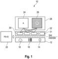
- a first embodiment of the new automation system is designated in its entirety with the reference number 10.
- the automation system 10 here comprises hardware and software components which together form a safe automation system.
- Safe in this context means that a Safety Integrity Level 3 according to IEC 61508 can be achieved by the automation system according to the invention for an implemented safety function.
- the automation system comprises a platform 12 that serves as a data processing device and computing unit.
- the platform 12 can be dedicated hardware 14, real or virtual computing systems 16, or infrastructure 18 located in a cloud.
- the platform 12 can also be composed of a combination of the aforementioned devices.
- the platform 12 is a non-secure platform or is at least partially made up of non-secure components.
- Non-secure here means that the components of the platform 12 do not have or cannot demonstrate sufficient inherent fault tolerance in accordance with the relevant safety standard to be able to implement a secure system on their own.
- the platform 12 can therefore be made up of, for example, commercially available PC hardware and in particular include standard processors.
- the platform or components of the platform can also be provided in the form of cloud computing.
- the platform 12 can consist of hardware and software components.
- the platform 12 can be a non-secure device, such as a PC or a Raspberry Pi, running a non-secure real-time operating system (RTOS), e.g. a Linux derivative.
- RTOS real-time operating system
- the automation system 10 further comprises at least one fail-safe peripheral module 20 for fail-safe input from the process and fail-safe output to the process.
- the fail-safe peripheral module 20 enables the connection of the automation system to the process.
- the fail-safe nature of the peripheral module 20 and safety-related communication between the peripheral module 20 and the automation system 10 is achieved by principles known from safety technology and is not the subject of this disclosure.
- the platform 12 and the fail-safe peripheral module 20 together form the substructure and the interfaces of the safe automation system 10, while a safe runtime environment 22 sitting on the platform as well as user programs 24, 26 implement the actual safety function 28.
- the secure runtime environment 22 is a software layer that is arranged between the platform 12 and the user programs 24, 26 and provides the user programs 24, 26 with secure resources 30 that are independent of the platform 12.
- the secure runtime environment 22 loads the user programs 24, 26, executes them on the platform and coordinates their mutual links.
- the secure runtime environment 22 thus represents a small platform itself with the aid of which the user programs 24, 26 are executed.
- the user programs 24, 26 are preferably designed specifically for the platform 12, i.e. written in a programming language that can be converted into native machine code of the platform 12 for execution.
- the secure runtime environment 22 is therefore not an "operating system" for executing the user programs 24, 26, but merely encapsulates secure resources 30 for the user programs 24, 26 so that they can be integrated by the user programs 24, 26 without the user programs 24, 26 having to ensure secure execution of the secure resources 30.
- the secure runtime environment 22 can in turn be divided into platform-specific components and platform-independent components, with the secure resources 30 in particular being implemented by platform-independent components so that the secure runtime environment 22 can be easily ported to different platforms.
- the safety function 28 can be any safety function, such as emergency stop, two-hand or decentralized I/O.
- the safety function 28 is thus a safety-related control function implemented by the automation system.
- the safety-related control function is implemented by two user programs 24, 26 that are executed in parallel.
- the user programs are diverse from one another, i.e. one and the same result is achieved by the user programs 24, 26 in different ways.
- a calculation is considered to be fully diverse if the mutual freedom from interaction of the parts of a processor used for the calculation or the mutual freedom from interaction of the different uses of the same parts of a processor.
- Such proof usually requires hardware tests, which can be omitted in the case of coded processing in the sense of SCP and may also be omitted in the automation system according to the invention if these hardware tests can be compensated for by additional tests and the secure resources 30 of the secure runtime environment and can be made externally verifiable.
- the diversity between the first and second application programs 24, 26 is achieved in that the second application program 26 works with diverse data for the first application program 24 and, as a result, uses different instructions for the same calculation steps.
- the use of inverse data does not provide complete diversity, but sufficient diversity to enable sufficient error security in conjunction with the secure runtime environment 22 and the tests 31 provided by the runtime environment 22.
- a program version that works with inverse data can easily be generated automatically from the native program version according to a fixed scheme.
- the inverse user program can thus be executed with comparable effort as the native user program.
- the inverse user program can work with the same data types and use the same instruction set, since calculations with inverse data are based on the same arithmetic.
- An inverse user program is therefore less complex than a coded user program that is based on arithmetic coding, for example AN coding.
- a tool chain for creating the inverse program version from the native program version can also be simplified. The simplified tool chain enables quick porting to other systems or the use of a different programming language. Overall, this increases the flexibility of the entire approach.
- the invention is therefore based, among other things, on the assumption that, although coded processing according to SCP can reveal execution errors in an application program more clearly and reliably than the diverse processing proposed here, the effort involved is not justified, since the application must always be integrated into a security model in order to achieve a high security rating.
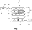
- Fig. 2 shows a schematic representation of a security model of an automation system according to a preferred embodiment of the present invention.
- the secure runtime environment 22 is based on a non-secure device 32 with a non-secure real-time operating system 34.
- the non-secure device 32 and the non-secure real-time operating system together form the platform 12.
- the secure runtime environment 22 is a software layer that, on the one hand, provides secure resources 30 for the user programs 24, 26 in a resource layer 36 that are independent of the platform 12 and, on the other hand, forms a local security instance 38 in order to monitor the user programs 24, 26 and the security function implemented by them.
- the user programs 24, 26 are connected to the process to be monitored via a secure peripheral module 20.
- the safe runtime environment 22 can in turn be monitored by a safe device.
- the safe device (hereinafter also referred to as Safety Pacemaker (SPM) 40) can be a simple hardware dongle, e.g. in the form of a commercially available USB stick, with one or more simple microcontrollers, such as a PIC and/or AVR. It goes without saying that a hardware dongle is not limited to a USB interface here, but the SPM 40 can also be connected via Ethernet, RS232 or another communication interface.
- the SPM 40 implements a second, preferably external security instance 41.
- the second security instance 41 tests the secure runtime environment 22, in particular the first local security instance 38, by means of targeted error injection.
- the error injection takes place via services and manipulators of the secure runtime environment 22, which are activated by the external security instance 41.
- data comparators, a system clock and timer tests of the secure runtime environment 22 can be checked and errors in the execution of the user programs 24, 26 can be revealed without corresponding tests having to be taken into account and/or implemented when developing the user programs 24, 26.
- the first user program 24 can thus be written in one channel without the application programmer having to take the security of the user program into account.
- a second user program 26, which is diverse to the first user program, can be generated automatically by a tool chain. The application developer can thus only worry about implementing the actual security function.
- the SPM 40 can additionally provide a safety clock 42, in particular to implement a second shutdown path on the safe peripheral module 20.
- Fig. 3 shows an architectural model in which an embodiment of the automation system 10 is embedded.
- the architectural model essentially comprises three components. These are the automation system 10, an external safety unit, such as the aforementioned SPM 40, and a communication interface 44 between these two components.
- All three components can have a hardware-neutral layer 46 and a hardware-specific layer 48.
- the secure runtime environment 22 decouples the hardware-specific layer 48 from the hardware-neutral layer 46 with a hardware-specific component, a so-called System Abstraction Layer (SAL).
- SAL 50 abstracts the secure runtime environment 22 from an operating system 52 and the associated hardware 54.
- Special hardware 56 which is addressed by operating system drivers 58, can be abstracted by independent SAL drivers 60.
- the automation system 10 implements a resource layer 36.
- the resource layer 36 provides the secure resources and, as shown here, is preferably present in duplicate and in a diverse manner.
- the resource layer 36 can provide timers and the process data for each channel.
- the resource layer 36 can provide safety-related functionalities, such as a secure CRC calculation.
- An application manager 62a, 62b is located on the resource layer 36, preferably separately for each user program 24, 26. When the two user programs 24, 26 start up, this checks their consistency and checks their CRC.
- the application manager 62a, 62b is also preferably responsible for the cyclical calling of the user programs, their execution monitoring and for the provision of an API.
- the API can contain functions for setting the outputs, for reading the inputs and for starting and reading the application timers.
- the application manager 62a, 62b is also preferably designed to be duplicated and diverse, as shown here.
- the secure runtime environment 22 of the automation system 10 further implements a local security instance 38.
- the local security instance 38 takes the necessary This includes RAM and ROM tests, cycle and sequence monitoring and timer tests.
- the local safety instance 38 also carries out the consistency check of the process data of the user programs 24, 26.
- the local safety instance 38 preferably runs only once on the system and can be checked externally via the SPM 40.
- the SPM 40 is a fail-safe device with safe hardware, which is formed, for example, from two redundant processors 64a, 64b, which enable safe execution of an application in a manner known per se. Since the SPM does not execute any user programs for control in the sense of the user programs of the automation system 10, the hardware can be designed to be particularly simple. In particular, special safe CPUs can be used for the processors 64a, 64b, for which proof of fail-safety can be provided in a practical manner, for example by FMEA.
- a second security instance 41 is executed on the SPM 40. This is preferably implemented in a hardware-neutral manner and is decoupled from the hardware by an abstraction layer 66. The second security instance 41 can communicate with the first security instance 38 of the automation system 10 via the communication interface 44.
- the communication interface 44 can be a single-channel communication interface without special safety precautions. The security of the communication can be ensured by the interaction of the local safety instance 38 of the automation system 10 and the second safety instance 41 of the external safety device.
- the secure runtime environment 22 and the SPM 40 communicate with each other in a fixed cycle with time-out monitoring.
- data e.g. timer values, sequence control, etc.
- the secure runtime environment 22 manipulators that can be activated by the SPM 40, for example by the SPM 40 sending a corresponding ID of the manipulators to the secure runtime environment 22.
- the SPM 40 then expects a suitable error message from the secure runtime environment 22.
- the SPM 40 has certain expectations of the secure runtime environment 22 after a manipulator ID has been transmitted.
- the safe runtime environment 22 must not have any error that is recognizable to the user due to the manipulators or switch off the outputs due to deliberate falsification. The error must therefore be intercepted by the safe runtime environment 22.
- the concept makes it possible to test the system behavior at the real point in the program.
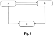
- Fig. 4 shows in a state diagram the possible states that SPM 40 and the automation system 10 can assume during a check.
- the secure runtime environment 22 waits for an error in order to be able to react to it accordingly. If the secure runtime environment 22 receives a manipulator ID in this state, preferably including a defined bit mask, the corresponding manipulator is activated by the SPM 40. The secure runtime environment 22 then goes into state B, in which it is desensitized to the corresponding error. This is followed by manipulation of the data to be processed in order to simulate an error. Preferably, the data is exclusively ORed with the received bit mask so that the faulty bit position can be rolled by the SPM 40.
- the secure runtime environment 22 must generate the appropriate error message in response to the manipulation, which the SPM 40 is waiting for. If the expectation does not occur, the secure runtime environment 22 and/or the SPM 40 can trigger a secure shutdown, for example by means of a second shutdown path.
- the second shutdown path can be in a preferred In this embodiment, the shutdown can be realized through the interaction of the SPM 40 and the safe peripheral module 20.
- other shutdown methods are also conceivable.
- the secure runtime environment 22 returns to the normal state A. If the error actually occurs during desensitization, it will be intercepted by the desensitization, but the test would not be successful, so that an unintercepted error message is transmitted to the SPM 40.
- all single-channel tests carried out in the local safety instance can be checked separately.
- the following single-channel tests can be checked by the external tests: input data comparisons, output data comparisons, RAM test, ROM test, timer test, cycle monitoring, sequence monitoring of the secure runtime environment 22 and sequence monitoring of the user programs 24, 26.
- Fig. 5 shows a schematic representation of an automation system according to a second embodiment of the present invention.
- the automation system according to the second embodiment is designated here in its entirety with the reference number 100. Parts with the same reference number designate the same parts as in the first embodiment and are not explained again below.
- the automation system 100 consists of three individual components.
- the first component is an automation system 10, which is based on a non-safe platform 12.
- the automation system is designed to implement a safety function 28 with the aid of two user programs 24, 26.
- the first component can thus comprise an automation system as described in Reference has been described to the first embodiment. However, it is to be understood that the first component is not limited to this embodiment, but any automation system is suitable as the first component.
- the second and third components are the monitoring device 70 and the fail-safe peripheral module 20.
- the monitoring device 70 can in particular be the previously described SPM, which was designated above with the reference number 40.
- the monitoring device 70 and the fail-safe peripheral module are coupled to the automation system 10 via a first communication interface 72 and a second communication interface 74.
- the first communication interface 72 and the second communication interface 74 also enable communication between the monitoring device 70 and the fail-safe peripheral module 20.
- the monitoring device 70 can communicate with the fail-safe peripheral module 20 via the platform 12.
- the first and second communication interfaces 72, 74 are here in particular single-channel communication interfaces, such as a commercially available USB interface. It goes without saying that other communication interfaces, such as Ethernet, RS232, etc., can equally be considered.
- the monitoring device 70 is preferably, as shown here, an independent hardware component that is designed to provide fail-safe services 76.
- the fail-safe services 76 can be implemented in software or in hardware, with the inherent fault safety being ensured by appropriate measures, for example by the services being designed with multi-channel redundancy or by executing them on multi-channel redundancy hardware in a manner known per se, so that fail-safe operation of the services 76 can be ensured and tested. It is understood that the fail-safe design is not limited to the form shown here, but other measures known to those skilled in the art for achieving inherent fault safety are also conceivable.
- the fail-safe services 76 are preferably simple services, such as a counter unit 78 and a coding unit 80 here.
- the fail-safe services 76 can thus be implemented on hardware that is simple and not very complex.
- the hardware of the monitoring device 70 can, for example, comprise one or more simple microcontrollers, ASICs or similar computing units, or can be composed of discrete electrical components. In particular, when using a microcontroller, its range of commands is as limited as possible so that certification with regard to inherent fault safety is possible at low cost.
- the hardware equipment of the monitoring device 70 is limited to being able to execute the counter unit 78 and coding unit 80.
- the fail-safe services 76 interact with the fail-safe peripheral module 20 so that, regardless of the implementation of the safety function 28, a safe shutdown can be ensured even in the event of a fault in the non-safe platform 12.
- the monitoring device 70 itself does not have any further safety-related devices, i.e. in particular no separate safe outputs that can directly cause an additional shutdown path for the safety-critical process.
- the coupling with the safety-critical process preferably takes place exclusively via the fail-safe peripheral module 20.
- the monitoring device 70 additionally has a test device 82 in the form of a safety instance, which interacts with a safe runtime environment 22 implemented on the platform 12 in order to provide additional test devices for the user programs 24, 26.
- the safe runtime environment 22 is implemented in a user program-unspecific manner and is identical for different automation systems 10.
- the safety of different safety functions 28 on different platforms 12 can be tested independently using a uniform test device 82, whereby the monitoring device 70 itself, as a last resort, can transfer the process to a safe state together with the fail-safe peripheral module.
- the monitoring device 70 can thus be used on various automation systems without additional adaptations. Likewise, the monitoring device 70 can be replaced by another one without great effort in the event of a defect.
- the essential aspect of the invention is the division of the safe control into different, in particular hardware-independent components.
- the focus of the first component is to provide as much computing capacity as possible for the implementation of the safety function 28 and to enable simple development of the associated user programs 24, 26.
- the focus of the second and third components is to make the hardware as simple as possible so that the fault tolerance of the services 76 provided can be reliably and cost-effectively guaranteed.
- Fig. 6 shows two embodiments of an automation system according to the second embodiment of the present invention.
- the three components of the automation system 100 are designed as independent hardware components. Both the monitoring device 70 and the fail-safe peripheral module 20 are each set up as a hardware component.
- a first communication interface 72 connects the monitoring device 70 to the automation system 10 and a second communication interface 74 connects the fail-safe peripheral module 20 to the automation system 10. Communication between the monitoring device 70 and the fail-safe peripheral module 20 therefore preferably takes place exclusively via the automation system 10.
- the design with separate components has the advantage that these can be manufactured and sold separately.
- a monitoring device 70 can be used for a large number of different peripheral modules 20.
- the automation system 100 can thus be adapted to the respective requirement, with only the peripheral module 20 having to be replaced.
- the monitoring device 70 and the fail-safe module 20 are implemented as a common hardware component.
- a first logical communication interface 72 and a second logical communication interface 74 are implemented here by a single physical connection to the automation system 10.
- communication between the monitoring device 70 and the fail-safe peripheral module 20 takes place via the first and second communication interfaces 72, 74, i.e. here too, communication between them takes place via the automation system 10.
- the monitoring device 70 and the fail-safe peripheral module 20 are two independent logical units despite the integration.
- a common secure hardware basis can advantageously be used for the monitoring device 70 and the fail-safe module 20.
- functions of the fail-safe peripheral module and of the monitoring device 70 can be implemented via common processors that operate redundantly on multiple channels.
- one physical communication interface is sufficient to implement the first and second communication interfaces. In this way, a secure automation system 100 in the sense of the present invention can be implemented particularly inexpensively.
- Fig. 7 shows a circuit diagram of a preferred embodiment of the automation system according to the invention according to the second embodiment.
- the automation system 100 here comprises a monitoring device 70, an automation system 10 and a fail-safe peripheral module 20, each as an independent hardware component.
- communication between the individual components takes place via a USB interface.
- the monitoring device 70 also has a counter unit 78 and a coding unit 80 to implement the fail-safe service 76.
- the counter unit 78 can continuously increment an internal counter and provide the coding unit 80 with a counter value C. Furthermore, the counter value C can be transmitted to the fail-safe peripheral module 20 via the communication interface 72, 74.
- the coding unit 80 receives a random value R from the automation system 10.
- the random value R is generated here by a random number generator 86 within the fail-safe peripheral module 20.
- the coding unit 80 generates a key value S from the random value R and the counter value C and transmits this to the fail-safe peripheral module 20 via the automation system 10.
- the monitoring device 70 checks whether the random value, which is preferably transmitted cyclically by the automation system 10, changes over time. Since the key value S is based on both the random value R and the continuous counter C, it can be ensured that all numbers are run through at least once. This means that the monitoring device 70 does not have to ensure whether a random generator that generates the random value actually runs through all values. Such an evaluation would be computationally intensive and thus difficult to carry out in a preferred embodiment of the monitoring device 70 with only low computing capacity.
- the fail-safe peripheral module 20 has complementary units to the units provided in the monitoring device 70. These can be designed as dedicated units or implemented in the form of software modules.
- the fail-safe peripheral module 20 comprises a decoding unit 88 and a comparator unit 90 as complementary units.
- the decoding unit 88 receives the continuous counter value C and a copy of the random value R and generates a comparison value S' from this. If the received key value S and the generated comparison value S' are identical, the fail-safe peripheral module 20 signals a safe state.
- the decoding is only known to the decoding unit 88 of the fail-safe peripheral module 20 and the coding is only known to the coding unit 78 of the monitoring device.
- the safe state is signaled using a first output circuit 91 with a first monostable flip-flop 92 and a second output circuit 93 with a second monostable flip-flop 94.
- the comparator 90 acts alternately via a switch 96 on the two output circuits 91, 93, i.e. here on the monoflops 92, 94.
- the fail-safe peripheral module 20 indicates a safe state when at least one of the two monoflops 92, 94 is triggered.
- both monoflops 92, 94 are usually triggered, i.e. the cycle time within which new keys are sent is correspondingly matched to the holding time of the monoflops 92, 94.
- the monitoring device 70 To test whether the fail-safe peripheral module 20 correctly signals the safe state, the monitoring device 70 generates an incorrect key value by inverting a bit of the correct key value S. This results in the comparator 90 detecting an inequality between the key value S and the generated intermediate value S' and interrupting the signal to the switch 96.
- one of the two monoflops drops out first and no longer supplies a signal at the output. This can be detected by the logic combination circuit 98 following the monoflops, whereupon a time-out signal 102 is generated. The time-out signal 102 can be read back by the monitoring device 70 so that it can determine whether an incorrect numerical value as the key value S leads to an expected drop in one of the two monoflops.
- the fail-safe peripheral module continues to signal a safe state, provided that the dropped monoflop is retriggered promptly by a correct key value S. If no timely Retriggering, the second monoflop also drops out and the fail-safe peripheral module 20 signals a non-safe state. In the present embodiment, signaling a non-safe state would result in the safe outputs 104 being switched off.
- the design with monoflops 92, 94 represents only one possible design of the output circuits 91, 93.
- the two branches can also be designed differently and only have to be able to be activated and deactivated.
- the output circuits are preferably set up to deactivate themselves after a defined period of time from activation. Alternatively, deactivation from the outside is also conceivable.
- the fail-safe peripheral module 20 can have additional test devices that can be combined with the watchdog protection.
- additional test devices that can be combined with the watchdog protection.
- two further input registers 108, 110 can be provided, which contain a previous and a subsequent value that can be used to detect address corruption.
- the fail-safe peripheral module 20 can have a safe clock generator 112 that provides a safe clock that can be used for various safety-related applications.
- Such an application can be, for example, a voltage monitoring device 114 that monitors a safe voltage supply and can possibly influence the safe outputs 104 of the fail-safe peripheral module 20.
- a restart lock 116 that prevents the safety-critical process from restarting on its own in the event of a fault.
Landscapes
- Engineering & Computer Science (AREA)
- Physics & Mathematics (AREA)
- General Physics & Mathematics (AREA)
- Automation & Control Theory (AREA)
- Computer Security & Cryptography (AREA)
- Computer Networks & Wireless Communication (AREA)
- Signal Processing (AREA)
- Safety Devices In Control Systems (AREA)
- Hardware Redundancy (AREA)
- Programmable Controllers (AREA)
- Debugging And Monitoring (AREA)
Claims (13)
- Système d'automatisation (100) pour la surveillance d'un processus critique pour la sécurité, comprenant- une plate-forme non sécurisée (12) pour l'exécution de programmes utilisateur (24, 26) qui réalisent une fonction de sécurité (28),- un module périphérique à sécurité intégrée (20), par l'intermédiaire duquel le processus critique pour la sécurité peut être couplé aux programmes utilisateur (24, 26), ainsi que- un dispositif de surveillance (70) qui est configuré pour sécuriser l'exécution de la fonction de sécurité (28) sur la plate-forme non sécurisée (12),dans lequel le dispositif de surveillance (70) peut être couplé à la plate-forme non sécurisée (12) par l'intermédiaire d'une première interface de communication (72) et le module périphérique à sécurité intégrée (20) peut être couplé à la plate-forme non sécurisée (12) par l'intermédiaire d'une seconde interface de communication (74),dans lequel le dispositif de surveillance (70) est configuré pour exécuter au moins un service de sécurité intégrée (76) indépendamment de la plate-forme non sécurisée (12) afin d'échanger de manière cyclique des données produites par le service de sécurité intégrée (76) avec le module périphérique à sécurité intégrée (20) selon un schéma défini, etdans lequel le module périphérique à sécurité intégrée (20) est configuré pour signaler un état sécurisé en fonction de la fonction de sécurité (28) réalisée et à l'aide de l'échange de données qui est effectué par l'intermédiaire de la plate-forme non sécurisée (12).
- Système d'automatisation selon la revendication 1, dans lequel le service de sécurité intégrée (76) comprend une unité formant compteur (78) qui est configurée pour générer une valeur de compteur continue (C), et une unité formant encodeur (80) qui est configurée pour générer une valeur clé (S), en particulier dans lequel l'unité formant encodeur (80) génère la valeur clé (S) à partir d'une valeur aléatoire (R) et de la valeur de compteur continue (C).
- Système d'automatisation selon la revendication 2, dans lequel la première interface de communication est en outre configurée pour transmettre la valeur de compteur continue (C) et la valeur clé (S) à la plate-forme non sécurisée (12), et dans lequel le module périphérique à sécurité intégrée (20) est configuré pour signaler l'état sécurisé en fonction de la fonction de sécurité réalisée, de la valeur clé (S) et de la valeur de compteur continue (C).
- Système d'automatisation selon l'une des revendications 1 à 3, dans lequel le dispositif de surveillance (70) est un composant matériel autonome pouvant être détaché de la plateforme non sécurisée (12) par un utilisateur, en particulier une clé électronique matérielle.
- Système d'automatisation selon l'une des revendications 1 à 3, dans lequel le dispositif de surveillance (70) est intégré dans le module périphérique à sécurité intégrée (20).
- Système d'automatisation selon l'une des revendications 1 à 5, dans lequel la première interface de communication (72) et/ou la seconde interface de communication (74) sont des interfaces de communication non sécurisées.
- Système d'automatisation selon la revendication 2, dans lequel le dispositif de surveillance (70) est configuré pour envoyer, à un moment défini, une valeur erronée ne correspondant pas à la valeur clé (S) en tant que valeur clé (S), en particulier dans lequel le dispositif de surveillance (70) est configuré pour inverser un bit de la valeur clé (S) pour produire la valeur erronée, de préférence par rotation.
- Système d'automatisation selon la revendication 2 ou 7, dans lequel le module périphérique à sécurité intégrée (20) comprend une unité formant décodeur (88) pour la production d'une valeur intermédiaire (S') à partir de la valeur de compteur continue (C) et d'une valeur aléatoire (R), ainsi qu'une unité formant comparateur (90) pour la comparaison de la valeur intermédiaire (S') avec la valeur clé (S).
- Système d'automatisation selon la revendication 8, dans lequel l'unité formant décodeur (88) et l'unité formant comparateur (90) sont mises en oeuvre avec une sécurité intégrée, en particulier dans lequel le module périphérique à sécurité intégrée (20) comprend un premier circuit de sortie (91) et un second circuit de sortie (93) qui peuvent être activés et désactivés et sur lesquels l'unité formant comparateur (90) agit alternativement, de sorte que le premier circuit de sortie (91) ou le second circuit de sortie (93) est alternativement activé, et dans lequel le module périphérique à sécurité intégrée (20) signale un état sécurisé lorsque le premier circuit de sortie (91) ou le second circuit de sortie (91, 93) est activé, et dans lequel, de préférence, le module périphérique à sécurité intégrée (20) est configuré pour, lorsqu'une valeur erronée est transmise en tant que valeur clé (S), produire un signal de temporisation par l'intermédiaire de l'un des deux circuits de sortie (91, 93) et pour signaler simultanément l'état sécurisé par l'intermédiaire de l'autre circuit de sortie.
- Système d'automatisation selon l'une des revendications 1 à 9, dans lequel le module périphérique à sécurité intégrée (20) comprend un générateur de nombres aléatoires sécurisé (86) pour produire une valeur aléatoire (R) ou est configuré pour recevoir une valeur aléatoire (R).
- Système d'automatisation selon l'une des revendications 1 à 10, dans lequel le module périphérique à sécurité intégrée (20) est un composant matériel autonome.
- Système d'automatisation selon l'une des revendications 1 à 11, dans lequel le dispositif de surveillance (70) et/ou le module périphérique à sécurité intégrée (20) sont conçus de manière redondante avec plusieurs canaux, et/ou dans lequel le module périphérique à sécurité intégrée (20) présente une horloge à sécurité intégrée (112).
- Procédé pour la surveillance d'un processus critique pour la sécurité avec un système d'automatisation, comportant les étapes consistant à :- fournir une plate-forme non sécurisée (12) pour l'exécution de programmes utilisateur (24, 26) qui réalisent une fonction de sécurité (28),- coupler le processus critique pour la sécurité avec les programmes utilisateur (24, 26) par l'intermédiaire d'un module périphérique à sécurité intégrée (20),- sécuriser l'exécution de la fonction de sécurité (28) sur la plate-forme non sécurisée (12) par un dispositif de surveillance (70),dans lequel le dispositif de surveillance (70) peut être couplé à la plate-forme non sécurisée (12) par l'intermédiaire d'une première interface de communication (72) et le module périphérique à sécurité intégrée (20) peut être couplé à la plate-forme non sécurisée (12) par l'intermédiaire d'une seconde interface de communication (74),dans lequel le dispositif de surveillance (70) exécute au moins un service de sécurité intégrée (76) indépendamment de la plate-forme non sécurisée (12) afin d'échanger de manière cyclique des données produites par le service de sécurité intégrée (76) avec le module périphérique à sécurité intégrée (20) selon un schéma défini, etdans lequel le module périphérique à sécurité intégrée (20) signale un état sécurisé en fonction de la fonction de sécurité (28) réalisée et à l'aide de l'échange de données qui est effectué par l'intermédiaire de la plate-forme non sécurisée (12).
Applications Claiming Priority (2)
| Application Number | Priority Date | Filing Date | Title |
|---|---|---|---|
| DE102018120344.6A DE102018120344B4 (de) | 2018-08-21 | 2018-08-21 | Automatisierungssystem zur Überwachung eines sicherheitskritischen Prozesses |
| PCT/EP2019/066172 WO2020038627A1 (fr) | 2018-08-21 | 2019-06-19 | Système d'automatisation de la surveillance d'un processus critique en matière de sécurité |
Publications (3)
| Publication Number | Publication Date |
|---|---|
| EP3841439A1 EP3841439A1 (fr) | 2021-06-30 |
| EP3841439C0 EP3841439C0 (fr) | 2024-11-06 |
| EP3841439B1 true EP3841439B1 (fr) | 2024-11-06 |
Family
ID=67001789
Family Applications (1)
| Application Number | Title | Priority Date | Filing Date |
|---|---|---|---|
| EP19732606.9A Active EP3841439B1 (fr) | 2018-08-21 | 2019-06-19 | Système d'automatisation de la surveillance d'un processus critique en matière de sécurité |
Country Status (6)
| Country | Link |
|---|---|
| US (1) | US11982984B2 (fr) |
| EP (1) | EP3841439B1 (fr) |
| JP (1) | JP7267400B2 (fr) |
| CN (1) | CN112740123B (fr) |
| DE (1) | DE102018120344B4 (fr) |
| WO (1) | WO2020038627A1 (fr) |
Families Citing this family (2)
| Publication number | Priority date | Publication date | Assignee | Title |
|---|---|---|---|---|
| US20220382239A1 (en) * | 2021-05-27 | 2022-12-01 | Fort Robotics, Inc. | Ensuring Functional Safety Requirement Satisfaction For Ouput Determination and Output of Safety Messages |
| DE102024129073A1 (de) * | 2024-10-09 | 2026-04-09 | Ifm Electronic Gmbh | Steuerungseinheit mit einer sicheren Software-Komponente |
Family Cites Families (63)
| Publication number | Priority date | Publication date | Assignee | Title |
|---|---|---|---|---|
| US6850252B1 (en) * | 1999-10-05 | 2005-02-01 | Steven M. Hoffberg | Intelligent electronic appliance system and method |
| DE4438714A1 (de) * | 1994-10-29 | 1996-05-02 | Bosch Gmbh Robert | Verfahren und Vorrichtung zur Steuerung der Antriebseinheit eines Fahrzeugs |
| US6918038B1 (en) * | 1996-08-13 | 2005-07-12 | Angel Secure Networks, Inc. | System and method for installing an auditable secure network |
| US6381506B1 (en) * | 1996-11-27 | 2002-04-30 | Victor Grappone | Fail-safe microprocessor-based control and monitoring of electrical devices |
| US6161202A (en) * | 1997-02-18 | 2000-12-12 | Ee-Signals Gmbh & Co. Kg | Method for the monitoring of integrated circuits |
| DE19754769A1 (de) | 1997-11-28 | 1999-06-02 | Siemens Ag | Feldbus-System für sicherheitsgerichtete Anwendungen |
| DE19834863A1 (de) * | 1998-08-01 | 2000-02-03 | Heidenhain Gmbh Dr Johannes | Verfahren zur sicheren Datenübertragung zwischen einer numerischen Steuerung und einem räumlich getrennten Gerät |
| US6343280B2 (en) * | 1998-12-15 | 2002-01-29 | Jonathan Clark | Distributed execution software license server |
| EP1043640A2 (fr) | 1999-04-09 | 2000-10-11 | Siemens Aktiengesellschaft | Système d'automatisation à sécurité intrinsèque avec un processeur standard et méthode pour un système d'automatisation à sécurité intrinsèque |
| US6523139B1 (en) * | 1999-12-17 | 2003-02-18 | Honeywell International Inc. | System and method for fail safe process execution monitoring and output control for critical systems |
| EP1305688A2 (fr) * | 2000-05-28 | 2003-05-02 | Yaron Mayer | Systeme et procede de protection generique generale complete d'ordinateurs contre des programmes pernicieux pouvant voler des informations et/ou provoquer des degats |
| DE10108962A1 (de) * | 2001-02-20 | 2002-09-12 | Pilz Gmbh & Co | Verfahren und Vorrichtung zum Programmieren einer Sicherheitssteuerung |
| US7734752B2 (en) * | 2002-02-08 | 2010-06-08 | Juniper Networks, Inc. | Intelligent integrated network security device for high-availability applications |
| WO2003107155A1 (fr) * | 2002-06-18 | 2003-12-24 | Honeywell International Inc. | Cle electronique pour reseau de communication de donnees securise |
| DE10240584A1 (de) * | 2002-08-28 | 2004-03-11 | Pilz Gmbh & Co. | Sicherheitssteuerung zum fehlersicheren Steuern von sicherheitskritischen Prozessen sowie Verfahren zum Aufspielen eines neuen Betriebsprogrammes auf eine solche |
| DE10320522A1 (de) * | 2003-05-02 | 2004-11-25 | Pilz Gmbh & Co. | Verfahren und Vorrichtug zum Steuern eines sicherheitskritischen Prozesses |
| DE102004039932A1 (de) * | 2004-08-17 | 2006-03-09 | Phoenix Contact Gmbh & Co. Kg | Verfahren und Vorrichtung zur Busankopplung sicherheitsrelevanter Prozesse |
| US7784080B2 (en) * | 2004-09-30 | 2010-08-24 | Smartvue Corporation | Wireless video surveillance system and method with single click-select actions |
| CN102013666A (zh) * | 2005-08-02 | 2011-04-13 | 菲尼克斯电气公司 | 三相功率放大器及用于其的换向开关装置 |
| DE102005037230A1 (de) * | 2005-08-08 | 2007-02-15 | Robert Bosch Gmbh | Verfahren und Vorrichtung zur Überwachung von Funktionen eines Rechnersystems |
| JP2006031727A (ja) * | 2005-08-17 | 2006-02-02 | Hitachi Ltd | フェールセーフコントローラ |
| DE102006046286A1 (de) * | 2005-12-16 | 2007-06-21 | Siemens Ag | Bewegungsüberwachung |
| EP1811421A1 (fr) * | 2005-12-29 | 2007-07-25 | AXSionics AG | Jeton de sécurité et procédé d'authentification d'un utilisateur au moyen du jeton de sécurité |
| ATE416403T1 (de) * | 2006-08-10 | 2008-12-15 | Sick Ag | Prozesssteuerung |
| FR2906380B1 (fr) * | 2006-09-27 | 2008-12-19 | Trusted Logic Sa | Systeme et procede de securisation de donnees. |
| US20090049307A1 (en) * | 2007-08-13 | 2009-02-19 | Authennex, Inc. | System and Method for Providing a Multifunction Computer Security USB Token Device |
| DE102007045398A1 (de) * | 2007-09-21 | 2009-04-02 | Continental Teves Ag & Co. Ohg | Integriertes Mikroprozessorsystem für sicherheitskritische Regelungen |
| DE102007062919A1 (de) * | 2007-12-21 | 2009-06-25 | Endress + Hauser Gmbh + Co. Kg | Vorrichtung zur Diagnose und/oder Ermittlung von Betriebs- bedingungen und/oder von Umgebungsbedingungen eines Feldgeräts der Prozessautomatisierungstechnik |
| DE102008004206A1 (de) * | 2008-01-14 | 2009-07-16 | Robert Bosch Gmbh | Anordnung und Verfahren zur Fehlererkennung und -behandlung in einem Steuergerät in einem Kraftfahrzeug |
| US8522354B2 (en) * | 2008-05-24 | 2013-08-27 | Via Technologies, Inc. | Microprocessor apparatus for secure on-die real-time clock |
| JP2010128511A (ja) * | 2008-11-25 | 2010-06-10 | Renesas Electronics Corp | マイクロコンピュータ及びフェイルセーフ対策方法 |
| DE102009011679A1 (de) * | 2009-02-23 | 2010-08-26 | Pilz Gmbh & Co. Kg | Verfahren und Vorrichtung zum Erstellen eines Anwenderprogrammes für eine Sicherheitssteuerung |
| DE102009019089A1 (de) * | 2009-04-20 | 2010-11-04 | Pilz Gmbh & Co. Kg | Verfahren und Vorrichtung zum Erstellen eines Anwenderprogramms für eine Sicherheitssteuerung |
| DE102010002346A1 (de) * | 2009-10-12 | 2011-04-14 | Endress + Hauser Gmbh + Co. Kg | Feldgerät zur Bestimmung oder Überwachung einer physikalischen oder chemischen Prozessgröße |
| JP5824457B2 (ja) * | 2009-11-23 | 2015-11-25 | ピルツ ゲーエムベーハー アンド コー.カーゲー | 運動変数のフェールセーフモニタリングのための安全回路およびモニタリング方法 |
| JP5494255B2 (ja) * | 2010-06-07 | 2014-05-14 | 富士電機株式会社 | 安全制御システム |
| US20130145401A1 (en) * | 2011-11-16 | 2013-06-06 | Flextronics Ap, Llc | Music streaming |
| EP2466505B1 (fr) * | 2010-12-01 | 2013-06-26 | Nagravision S.A. | Procédé d'authentification de terminal |
| US8464102B2 (en) * | 2010-12-23 | 2013-06-11 | GM Global Technology Operations LLC | Methods and systems for diagnosing hardware and software faults using time-stamped events |
| DE102012003242A1 (de) * | 2012-02-20 | 2013-08-22 | Phoenix Contact Gmbh & Co. Kg | Verfahren zum ausfallsicheren Betreiben eines Prozesssteuersystems mit redundanten Steuereinrichtungen |
| DE102012101516A1 (de) * | 2012-02-24 | 2013-08-29 | Pilz Gmbh & Co. Kg | Sicherheitsschaltvorrichtung mit Netzteil |
| DE102012101933B4 (de) | 2012-03-07 | 2013-12-05 | Pilz Gmbh & Co. Kg | Sensoranordnung zum Detektieren eines sicheren Anlagenzustandes einer automatisiert betriebenen Anlage |
| JP6163735B2 (ja) * | 2012-11-13 | 2017-07-19 | オムロン株式会社 | 安全スレーブユニット、その制御方法、その制御プログラム、および安全制御システム |
| US9560014B2 (en) * | 2013-01-23 | 2017-01-31 | Mcafee, Inc. | System and method for an endpoint hardware assisted network firewall in a security environment |
| US9251384B1 (en) * | 2013-03-07 | 2016-02-02 | Amazon Technologies, Inc. | Trusted peripheral device for a host in a shared electronic environment |
| US10375047B2 (en) * | 2013-09-30 | 2019-08-06 | Schneider Electric Industries Sas | Cloud-authenticated site resource management devices, apparatuses, methods and systems |
| US9589637B1 (en) * | 2013-12-18 | 2017-03-07 | Nxp Usa, Inc. | Storage element with storage and clock tree monitoring circuit and methods therefor |
| DE102014100970A1 (de) * | 2014-01-28 | 2015-07-30 | Pilz Gmbh & Co. Kg | Verfahren und Vorrichtung zum sicheren Abschalten einer elektrischen Last |
| US9998426B2 (en) * | 2014-01-30 | 2018-06-12 | Sierra Nevada Corporation | Bi-directional data security for control systems |
| DE102014106166B4 (de) * | 2014-05-02 | 2026-01-29 | Pilz Gmbh & Co. Kg | Vorrichtung und Verfahren zum fehlersicheren Überwachen eines beweglichen Maschinenteils |
| DE102014208848A1 (de) * | 2014-05-12 | 2015-11-12 | Robert Bosch Gmbh | Verfahren zum Überwachen eines elektronischen Sicherheitsmoduls |
| DE102015201298A1 (de) * | 2015-01-26 | 2016-07-28 | Robert Bosch Gmbh | Verfahren zum kryptographischen Bearbeiten von Daten |
| DE102015209897B3 (de) * | 2015-05-29 | 2016-08-18 | Siemens Aktiengesellschaft | Verfahren und Vorrichtung zur Plausibilisierung von sicherheitsrelevanten Größen |
| US9716710B2 (en) * | 2015-06-26 | 2017-07-25 | Intel Corporation | Technologies for virtualized access to security services provided by a converged manageability and security engine |
| US10397019B2 (en) * | 2015-11-16 | 2019-08-27 | Polysync Technologies, Inc. | Autonomous vehicle platform and safety architecture |
| DE102015122066A1 (de) * | 2015-12-17 | 2017-06-22 | Weidmüller Interface GmbH & Co. KG | Fehlersicheres Modul zum Anschluss an einen Feldbuskoppler, Feldbuskoppler, System und Verfahren zum Konfigurieren eines derartigen fehlersicheren Moduls |
| JP2017151496A (ja) * | 2016-02-22 | 2017-08-31 | ルネサスエレクトロニクス株式会社 | 安全監視装置、ネットワークシステム、安全監視方法 |
| EP3229437A1 (fr) * | 2016-04-07 | 2017-10-11 | Walter Steven Rosenbaum | Dispositif de communication et procédé de protection d'un système de communication contre l'application d'un code non autorisé |
| EP3270238B1 (fr) * | 2016-07-13 | 2020-05-20 | Siemens Aktiengesellschaft | Procédé de commande d'un entraînement |
| US20180121321A1 (en) * | 2016-11-02 | 2018-05-03 | N.Io Innovation, Llc | System And Method For Monitoring Services And Blocks Within A Configurable Platform Instance |
| GB2565875B (en) * | 2017-06-15 | 2023-02-08 | Fisher Rosemount Systems Inc | Systems and apparatus for distribution of batch and continuous process control data to remote devices |
| DE102017123295A1 (de) * | 2017-10-06 | 2019-04-11 | Pilz Gmbh & Co. Kg | Sicherheitssystem zur Absicherung eines kooperativen Betriebs von Menschen, Robotern und Maschinen |
| DE102018120347A1 (de) * | 2018-08-21 | 2020-02-27 | Pilz Gmbh & Co. Kg | Automatisierungssystem zur Überwachung eines sicherheitskritischen Prozesses |
-
2018
- 2018-08-21 DE DE102018120344.6A patent/DE102018120344B4/de active Active
-
2019
- 2019-06-19 CN CN201980061219.3A patent/CN112740123B/zh active Active
- 2019-06-19 EP EP19732606.9A patent/EP3841439B1/fr active Active
- 2019-06-19 JP JP2021509878A patent/JP7267400B2/ja active Active
- 2019-06-19 WO PCT/EP2019/066172 patent/WO2020038627A1/fr not_active Ceased
-
2021
- 2021-02-20 US US17/180,755 patent/US11982984B2/en active Active
Also Published As
| Publication number | Publication date |
|---|---|
| JP7267400B2 (ja) | 2023-05-01 |
| JP2021534507A (ja) | 2021-12-09 |
| DE102018120344A1 (de) | 2020-02-27 |
| EP3841439C0 (fr) | 2024-11-06 |
| EP3841439A1 (fr) | 2021-06-30 |
| CN112740123B (zh) | 2024-03-19 |
| WO2020038627A1 (fr) | 2020-02-27 |
| US11982984B2 (en) | 2024-05-14 |
| US20210278815A1 (en) | 2021-09-09 |
| CN112740123A (zh) | 2021-04-30 |
| DE102018120344B4 (de) | 2024-11-21 |
Similar Documents
| Publication | Publication Date | Title |
|---|---|---|
| EP3841438B1 (fr) | Système d'automatisation de la surveillance d'un processus critique en matière de sécurité | |
| EP2641176B1 (fr) | Système ä microprocesseurs a architecture tolérante aux fautes | |
| EP1680736A2 (fr) | Procede et dispositif de commutation entre au moins deux modes de fonctionnement d'une unite de processeur | |
| EP2513796B1 (fr) | Procédé permettant de faire fonctionner une unité de calcul | |
| DE19509150C2 (de) | Verfahren zum Steuern und Regeln von Fahrzeug-Bremsanlagen sowie Fahrzeug-Bremsanlage | |
| WO2010121796A1 (fr) | Commande de sécurité et procédé de commande d'une installation automatisée | |
| EP1043641A2 (fr) | Système d'automatisation à sécurité intrinsèque avec un processeur standard et méthode pour un système d'automatisation à sécurité intrinsèque | |
| DE10219501B4 (de) | System und Verfahren zur Verbesserung von Fehlerbeherrschungsmassnahmen, insbesondere in Automatisierungssystemen | |
| EP3657288A1 (fr) | Surveillance sécurisée de la tension | |
| EP3841439B1 (fr) | Système d'automatisation de la surveillance d'un processus critique en matière de sécurité | |
| WO2005045665A1 (fr) | Procede et dispositif de traitement d'operandes dans un processeur | |
| DE102004037713A1 (de) | Verfahren, Betriebssystem und Rechengerät zum Abarbeiten eines Computerprogramms | |
| EP2228723B1 (fr) | Procédé de gestion des erreurs d'un système de calcul | |
| EP3338189A2 (fr) | Procédé de fonctionnement d'un processeur multicoeur | |
| DE102004051991A1 (de) | Verfahren, Betriebssystem und Rechengerät zum Abarbeiten eines Computerprogramms | |
| DE102006012042A1 (de) | Steuervorrichtung zur fehlersicheren Steuerung einer Maschine | |
| DE102011007467A1 (de) | Mehrkernige integrierte Mikroprozessorschaltung mit Prüfeinrichtung, Prüfverfahren und Verwendung | |
| EP2133764B1 (fr) | Système d'automatisation à sécurité intrinsèque et procédé | |
| EP1316884A2 (fr) | Méthode de génération et/ou d' exécution diversifié du déroulement d'un programme | |
| EP1433061A2 (fr) | Procede d'essai du calculateur central d'un microprocesseur ou d'un microcontroleur | |
| EP1162540A1 (fr) | Dispositif et procédure de synchronisation d'un système des unités couplées de traitement des données | |
| DE10233879B4 (de) | Verfahren zum Steuern und Überwachen einer sicherheitskritischen Anlage, insbesondere Verkehrs-Signalanlage sowie Vorrichtung zur Durchführung des Verfahrens | |
| DE102016217762A1 (de) | Überwachung von sicherheitsrelevanten Funktionen durch eine nicht sichere Recheneinheit | |
| EP1915691A1 (fr) | Dispositif et procede pour commander un systeme informatique | |
| EP2583178A1 (fr) | Dispositif et procédé de commande d'une machine par un code de programme codé et non codé |
Legal Events
| Date | Code | Title | Description |
|---|---|---|---|
| STAA | Information on the status of an ep patent application or granted ep patent |
Free format text: STATUS: UNKNOWN |
|
| STAA | Information on the status of an ep patent application or granted ep patent |
Free format text: STATUS: THE INTERNATIONAL PUBLICATION HAS BEEN MADE |
|
| PUAI | Public reference made under article 153(3) epc to a published international application that has entered the european phase |
Free format text: ORIGINAL CODE: 0009012 |
|
| STAA | Information on the status of an ep patent application or granted ep patent |
Free format text: STATUS: REQUEST FOR EXAMINATION WAS MADE |
|
| 17P | Request for examination filed |
Effective date: 20210318 |
|
| AK | Designated contracting states |
Kind code of ref document: A1 Designated state(s): AL AT BE BG CH CY CZ DE DK EE ES FI FR GB GR HR HU IE IS IT LI LT LU LV MC MK MT NL NO PL PT RO RS SE SI SK SM TR |
|
| DAV | Request for validation of the european patent (deleted) | ||
| DAX | Request for extension of the european patent (deleted) | ||
| STAA | Information on the status of an ep patent application or granted ep patent |
Free format text: STATUS: EXAMINATION IS IN PROGRESS |
|
| 17Q | First examination report despatched |
Effective date: 20220809 |
|
| GRAP | Despatch of communication of intention to grant a patent |
Free format text: ORIGINAL CODE: EPIDOSNIGR1 |
|
| STAA | Information on the status of an ep patent application or granted ep patent |
Free format text: STATUS: GRANT OF PATENT IS INTENDED |
|
| INTG | Intention to grant announced |
Effective date: 20240607 |
|
| GRAS | Grant fee paid |
Free format text: ORIGINAL CODE: EPIDOSNIGR3 |
|
| GRAA | (expected) grant |
Free format text: ORIGINAL CODE: 0009210 |
|
| STAA | Information on the status of an ep patent application or granted ep patent |
Free format text: STATUS: THE PATENT HAS BEEN GRANTED |
|
| AK | Designated contracting states |
Kind code of ref document: B1 Designated state(s): AL AT BE BG CH CY CZ DE DK EE ES FI FR GB GR HR HU IE IS IT LI LT LU LV MC MK MT NL NO PL PT RO RS SE SI SK SM TR |
|
| REG | Reference to a national code |
Ref country code: GB Ref legal event code: FG4D Free format text: NOT ENGLISH |
|
| REG | Reference to a national code |
Ref country code: CH Ref legal event code: EP |
|
| REG | Reference to a national code |
Ref country code: DE Ref legal event code: R096 Ref document number: 502019012442 Country of ref document: DE |
|
| REG | Reference to a national code |
Ref country code: IE Ref legal event code: FG4D Free format text: LANGUAGE OF EP DOCUMENT: GERMAN |
|
| U01 | Request for unitary effect filed |
Effective date: 20241127 |
|
| U07 | Unitary effect registered |
Designated state(s): AT BE BG DE DK EE FI FR IT LT LU LV MT NL PT RO SE SI Effective date: 20241204 |
|
| PG25 | Lapsed in a contracting state [announced via postgrant information from national office to epo] |
Ref country code: HR Free format text: LAPSE BECAUSE OF FAILURE TO SUBMIT A TRANSLATION OF THE DESCRIPTION OR TO PAY THE FEE WITHIN THE PRESCRIBED TIME-LIMIT Effective date: 20241106 Ref country code: IS Free format text: LAPSE BECAUSE OF FAILURE TO SUBMIT A TRANSLATION OF THE DESCRIPTION OR TO PAY THE FEE WITHIN THE PRESCRIBED TIME-LIMIT Effective date: 20250306 |
|
| PG25 | Lapsed in a contracting state [announced via postgrant information from national office to epo] |
Ref country code: ES Free format text: LAPSE BECAUSE OF FAILURE TO SUBMIT A TRANSLATION OF THE DESCRIPTION OR TO PAY THE FEE WITHIN THE PRESCRIBED TIME-LIMIT Effective date: 20241106 |
|
| PG25 | Lapsed in a contracting state [announced via postgrant information from national office to epo] |
Ref country code: NO Free format text: LAPSE BECAUSE OF FAILURE TO SUBMIT A TRANSLATION OF THE DESCRIPTION OR TO PAY THE FEE WITHIN THE PRESCRIBED TIME-LIMIT Effective date: 20250206 |
|
| PG25 | Lapsed in a contracting state [announced via postgrant information from national office to epo] |
Ref country code: GR Free format text: LAPSE BECAUSE OF FAILURE TO SUBMIT A TRANSLATION OF THE DESCRIPTION OR TO PAY THE FEE WITHIN THE PRESCRIBED TIME-LIMIT Effective date: 20250207 |
|
| PG25 | Lapsed in a contracting state [announced via postgrant information from national office to epo] |
Ref country code: PL Free format text: LAPSE BECAUSE OF FAILURE TO SUBMIT A TRANSLATION OF THE DESCRIPTION OR TO PAY THE FEE WITHIN THE PRESCRIBED TIME-LIMIT Effective date: 20241106 |
|
| PG25 | Lapsed in a contracting state [announced via postgrant information from national office to epo] |
Ref country code: RS Free format text: LAPSE BECAUSE OF FAILURE TO SUBMIT A TRANSLATION OF THE DESCRIPTION OR TO PAY THE FEE WITHIN THE PRESCRIBED TIME-LIMIT Effective date: 20250206 |
|
| PG25 | Lapsed in a contracting state [announced via postgrant information from national office to epo] |
Ref country code: SM Free format text: LAPSE BECAUSE OF FAILURE TO SUBMIT A TRANSLATION OF THE DESCRIPTION OR TO PAY THE FEE WITHIN THE PRESCRIBED TIME-LIMIT Effective date: 20241106 |
|
| PG25 | Lapsed in a contracting state [announced via postgrant information from national office to epo] |
Ref country code: SK Free format text: LAPSE BECAUSE OF FAILURE TO SUBMIT A TRANSLATION OF THE DESCRIPTION OR TO PAY THE FEE WITHIN THE PRESCRIBED TIME-LIMIT Effective date: 20241106 |
|
| PG25 | Lapsed in a contracting state [announced via postgrant information from national office to epo] |
Ref country code: CZ Free format text: LAPSE BECAUSE OF FAILURE TO SUBMIT A TRANSLATION OF THE DESCRIPTION OR TO PAY THE FEE WITHIN THE PRESCRIBED TIME-LIMIT Effective date: 20241106 |
|
| U20 | Renewal fee for the european patent with unitary effect paid |
Year of fee payment: 7 Effective date: 20250627 |
|
| PLBE | No opposition filed within time limit |
Free format text: ORIGINAL CODE: 0009261 |
|
| STAA | Information on the status of an ep patent application or granted ep patent |
Free format text: STATUS: NO OPPOSITION FILED WITHIN TIME LIMIT |
|
| 26N | No opposition filed |
Effective date: 20250807 |
|
| PGFP | Annual fee paid to national office [announced via postgrant information from national office to epo] |
Ref country code: CH Payment date: 20250701 Year of fee payment: 7 |
|
| PG25 | Lapsed in a contracting state [announced via postgrant information from national office to epo] |
Ref country code: MC Free format text: LAPSE BECAUSE OF FAILURE TO SUBMIT A TRANSLATION OF THE DESCRIPTION OR TO PAY THE FEE WITHIN THE PRESCRIBED TIME-LIMIT Effective date: 20241106 |
|
| GBPC | Gb: european patent ceased through non-payment of renewal fee |
Effective date: 20250619 |
|
| PG25 | Lapsed in a contracting state [announced via postgrant information from national office to epo] |
Ref country code: GB Free format text: LAPSE BECAUSE OF NON-PAYMENT OF DUE FEES Effective date: 20250619 |
|
| PG25 | Lapsed in a contracting state [announced via postgrant information from national office to epo] |
Ref country code: IE Free format text: LAPSE BECAUSE OF NON-PAYMENT OF DUE FEES Effective date: 20250619 |