EP3841777B1 - Identification et atténuation de brouillage à distance - Google Patents
Identification et atténuation de brouillage à distance Download PDFInfo
- Publication number
- EP3841777B1 EP3841777B1 EP18930083.3A EP18930083A EP3841777B1 EP 3841777 B1 EP3841777 B1 EP 3841777B1 EP 18930083 A EP18930083 A EP 18930083A EP 3841777 B1 EP3841777 B1 EP 3841777B1
- Authority
- EP
- European Patent Office
- Prior art keywords
- interference
- symbols
- remote
- determining
- base station
- Prior art date
- Legal status (The legal status is an assumption and is not a legal conclusion. Google has not performed a legal analysis and makes no representation as to the accuracy of the status listed.)
- Active
Links
Images


Classifications
-
- H—ELECTRICITY
- H04—ELECTRIC COMMUNICATION TECHNIQUE
- H04L—TRANSMISSION OF DIGITAL INFORMATION, e.g. TELEGRAPHIC COMMUNICATION
- H04L25/00—Baseband systems
- H04L25/02—Details ; arrangements for supplying electrical power along data transmission lines
- H04L25/03—Shaping networks in transmitter or receiver, e.g. adaptive shaping networks
- H04L25/03006—Arrangements for removing intersymbol interference
-
- H—ELECTRICITY
- H04—ELECTRIC COMMUNICATION TECHNIQUE
- H04J—MULTIPLEX COMMUNICATION
- H04J11/00—Orthogonal multiplex systems, e.g. using WALSH codes
- H04J11/0023—Interference mitigation or co-ordination
- H04J11/005—Interference mitigation or co-ordination of intercell interference
- H04J11/0056—Inter-base station aspects
-
- H—ELECTRICITY
- H04—ELECTRIC COMMUNICATION TECHNIQUE
- H04B—TRANSMISSION
- H04B17/00—Monitoring; Testing
- H04B17/30—Monitoring; Testing of propagation channels
- H04B17/309—Measuring or estimating channel quality parameters
- H04B17/345—Interference values
-
- H—ELECTRICITY
- H04—ELECTRIC COMMUNICATION TECHNIQUE
- H04W—WIRELESS COMMUNICATION NETWORKS
- H04W24/00—Supervisory, monitoring or testing arrangements
- H04W24/02—Arrangements for optimising operational condition
-
- H—ELECTRICITY
- H04—ELECTRIC COMMUNICATION TECHNIQUE
- H04W—WIRELESS COMMUNICATION NETWORKS
- H04W24/00—Supervisory, monitoring or testing arrangements
- H04W24/08—Testing, supervising or monitoring using real traffic
-
- H—ELECTRICITY
- H04—ELECTRIC COMMUNICATION TECHNIQUE
- H04W—WIRELESS COMMUNICATION NETWORKS
- H04W36/00—Hand-off or reselection arrangements
- H04W36/06—Reselecting a communication resource in the serving access point
-
- H—ELECTRICITY
- H04—ELECTRIC COMMUNICATION TECHNIQUE
- H04W—WIRELESS COMMUNICATION NETWORKS
- H04W72/00—Local resource management
- H04W72/04—Wireless resource allocation
- H04W72/044—Wireless resource allocation based on the type of the allocated resource
- H04W72/0446—Resources in time domain, e.g. slots or frames
-
- H—ELECTRICITY
- H04—ELECTRIC COMMUNICATION TECHNIQUE
- H04W—WIRELESS COMMUNICATION NETWORKS
- H04W72/00—Local resource management
- H04W72/20—Control channels or signalling for resource management
- H04W72/27—Control channels or signalling for resource management between access points
-
- H—ELECTRICITY
- H04—ELECTRIC COMMUNICATION TECHNIQUE
- H04B—TRANSMISSION
- H04B7/00—Radio transmission systems, i.e. using radiation field
- H04B7/22—Scatter propagation systems, e.g. ionospheric, tropospheric or meteor scatter
-
- H—ELECTRICITY
- H04—ELECTRIC COMMUNICATION TECHNIQUE
- H04L—TRANSMISSION OF DIGITAL INFORMATION, e.g. TELEGRAPHIC COMMUNICATION
- H04L1/00—Arrangements for detecting or preventing errors in the information received
- H04L1/0001—Systems modifying transmission characteristics according to link quality, e.g. power backoff
- H04L1/0002—Systems modifying transmission characteristics according to link quality, e.g. power backoff by adapting the transmission rate
- H04L1/0003—Systems modifying transmission characteristics according to link quality, e.g. power backoff by adapting the transmission rate by switching between different modulation schemes
-
- H—ELECTRICITY
- H04—ELECTRIC COMMUNICATION TECHNIQUE
- H04L—TRANSMISSION OF DIGITAL INFORMATION, e.g. TELEGRAPHIC COMMUNICATION
- H04L1/00—Arrangements for detecting or preventing errors in the information received
- H04L1/0001—Systems modifying transmission characteristics according to link quality, e.g. power backoff
- H04L1/0009—Systems modifying transmission characteristics according to link quality, e.g. power backoff by adapting the channel coding
-
- H—ELECTRICITY
- H04—ELECTRIC COMMUNICATION TECHNIQUE
- H04W—WIRELESS COMMUNICATION NETWORKS
- H04W72/00—Local resource management
- H04W72/50—Allocation or scheduling criteria for wireless resources
- H04W72/54—Allocation or scheduling criteria for wireless resources based on quality criteria
- H04W72/541—Allocation or scheduling criteria for wireless resources based on quality criteria using the level of interference
-
- H—ELECTRICITY
- H04—ELECTRIC COMMUNICATION TECHNIQUE
- H04W—WIRELESS COMMUNICATION NETWORKS
- H04W92/00—Interfaces specially adapted for wireless communication networks
- H04W92/16—Interfaces between hierarchically similar devices
- H04W92/20—Interfaces between hierarchically similar devices between access points
Definitions
- This document is directed generally to wireless communications.
- Wireless communication technologies are moving the world toward an increasingly connected and networked society.
- the rapid growth of wireless communications and advances in technology has led to greater demand for capacity and connectivity.
- Other aspects, such as energy consumption, device cost, spectral efficiency, and latency are also important to meeting the needs of various communication scenarios.
- next generation systems and wireless communication techniques need to provide support for an increased number of users and devices, as well as support for higher data rates, therein requiring capabilities to mitigate different types of interference that occur.
- 3GPP R1-1808785 relates to mechanisms for improving network robustness.
- 3GPP R1-1808325 relates to remote interference management and mechanisms for improving network robustness.
- 3GPP R1-1808786 relates to mechanisms for identifying strong next generation NodeB interferers.
- This document relates to methods, systems, and devices for identifying and mitigating remote interference, which is when downlink transmissions from a remote network device (e.g., base station, evolved NodeB (eNB), next generation NodeB (gNB) and so on) interference with the local uplink transmissions of another network device, thereby improving system performance.
- a remote network device e.g., base station, evolved NodeB (eNB), next generation NodeB (gNB) and so on
- a wireless communication method includes determining that an interference type is a remote interference, and transmitting, in response to the determining, a reference signal indicative of a resource that was affected by the remote interference.
- a wireless communication method includes detecting a reference signal in a frame, and determining a resource that was affected by a remote interference based on a position of the reference signal in the frame.
- the above-described methods are embodied in the form of processor-executable code and stored in a computer-readable program medium.
- a device that is configured or operable to perform the above-described methods is disclosed.
- TD-LTE time-domain LTE
- RI remote interference
- eNBs and gNBs due to Interference over Thermal level (IoT) from remote interference, intermittently deteriorates thereby severely impacting network coverage and connection success rate.
- IoT degradation is typically caused by the downlink transmissions of a remote network eNB as long as the atmospheric conditions support the formation of atmospheric ducts.
- the present document discloses methods, systems and devices that overcome the deleterious effects of remote interference.
- this is achieved by the local gNB (referred to as the victim gNB, or the affected gNB, since it is the one being affected) identifying the interference present as remote interference (as compared to other sources of interference, e.g. uplink transmissions of neighboring cells), and the remote gNB (referred to as the aggressor gNB, or the interference-causing gNB, since it is the cause of the remote interference) deducing how many UL resources of the affected gNB were affected by its transmissions.
- the victim gNB referred to as the victim gNB, or the affected gNB, since it is the one being affected
- the remote gNB referred to as the aggressor gNB, or the interference-causing gNB, since it is the cause of the remote interference
- the present document uses section headings and sub-headings for facilitating easy understanding and not for limiting the scope of the disclosed techniques and embodiments to certain sections. Accordingly, embodiments disclosed in different sections can be used with each other. Furthermore, the present document uses examples from the 3GPP New Radio (NR) network architecture and 5G protocol only to facilitate understanding and the disclosed techniques and embodiments may be practiced in other wireless systems that use different communication protocols than the 3GPP protocols.
- NR 3GPP New Radio
- the local gNB (or eNB, network device, base station, and so on) may be affected by various types of interference, including uplink transmissions from neighboring gNBs, the local gNB must first identify that the interference present is remote interference.
- the local gNB determines that the uplink interference measurement results are higher than or equal to a first threshold, and at least one of the following conditions are satisfied. For example, the local gNB may determine that the measurements results of interference of thermal (IoT) or background noise are higher than or equal to the first threshold. In another example, the measurement results of RSSI (received signal strength indicator) are higher or equal to the first threshold. RSSI can include co-channel interference, adjacent-channel interference and thermal noise. The measurement method of RSSI in base station side is similar to RSSI of UE side defined in 3GPP TS38.215/T836.214.
- the neighboring cell Before the first base station performs an uplink interference measurement, the neighboring cell is notified by backhaul (e.g., Xn signaling) or air signaling to stop transmission (e.g. UL transmission) on the measurement resource of the first base station, e.g., the neighboring device temporarily ceases (mutes) its transmission.
- backhaul e.g., Xn signaling
- air signaling e.g. UL transmission
- 70% of RI comes from the interference source with distances ⁇ 200 km, with the furthest recorded interference source being 300 km away. Setting the GP to 9 symbols will solve the RI problem 70% of the time. In other words, 70% of RI interference sources are less than the distance range with 9 symbols delay from local base stations.
- the affected BS may send RIM-RS on the last one or more symbols of DwPTS, which may be detected on the interference-causing BS's UpPTS or subsequent UL slot.
- the interference-causing BS monitors RIM-RS on the UL symbols in UpPTS and subsequent UL slot. If the interference-causing BS detects the RIM-RS in the UL symbols, it confirms that the UL symbols and the previous UL symbols are interfered with remote interference. It should be noted that these UL symbols are after DL symbols or the flexible/GP symbols in a DL and UL transmission period.
- the interference-causing BS can determine how many UL resources of the affected BS are interfered with remote interference caused by the interference-causing BS.
- the SCS can be equal to greater than 15 kHz, such as 30kHz, 60kHz, 120kHz, 240kHz.
- 15 kHz such as 30kHz, 60kHz, 120kHz, 240kHz.
- one slot has a duration of 0.5 ms.
- GP + UpPTS + 1 UL slot is still equal to 19 OFDM symbols, but the duration of 19 symbols is reduced by half, which corresponds about a 200 km transmission distance. This implies that if the RIM-RS continues to be sent on the last one or more symbols of DwPTS by the affected BS, RIM-RS will most likely fall on the DL slot after the UpPTS and subsequent UL slot in the interference-causing BS side. If so, the interference-causing BS may not be able to detect RIM-RS on the UpPTS or subsequent UL slot.
- the following schemes may be employed in some embodiments of the disclosed technology.
- the first base station sends the signal (RIM-RS) on the last one or more symbols before the flexible symbols or before the guard period symbols.
- the second base station detects the signal on the UL symbols after the flexible symbols or guard period symbols and subsequent slots (e.g. m slots).
- the subsequent slots may be UL slots, or DL slots, or special slots, or any combination thereof.
- the number of slots m detected by the second base station depends on the subcarrier spacing. For example,
- the second base station if the second base station detects the signal in the DL, symbols, it confirms that UL symbols prior to the DL symbols, in a DL and UL transmission period, are interfered with remote interference. In other embodiments, if the second base station detects the signal in the UL symbols, it confirms that the UL symbols and the previous UL symbols, in a DL and UL transmission period, are interfered with remote interference.
- the first base station sends the signal on the last one or more symbols before the flexible symbols or before the guard period symbols.
- the second base station always detects the signal. If the second base station detects the signal in the UL symbols, it confirms that the UL symbols and the previous UL symbols are interfered with remote interference.
- the first base station sends multiple of the signal (RIM-RS) on the DL symbols before the flexible symbols or before the guard period symbols, e.g. in DwPTS and prior DL slots in a DL and UL transmission period.
- These signals (RIM-RS) located in different DL symbols may be the same, or carry different information.
- the former case results in these signals being transmitted repeatedly and has same generating sequence.
- the latter case results in these signals carrying different information, e.g., base station identity information, the timing information, etc., and be generated with different generating sequences or scrambling sequences.
- the second base station detects the signal on the UL symbols after the flexible symbols or guard period symbols. The last received signal is used to identified the UL interfered resources. If the second base station detects many signals in some UL symbols, it deduces that the UL symbols in which it detects the last signal and the previous UL symbols, in a DL and UL transmission period, are interfered with remote interference.
- the density of the signals transmitted in DwPTS and DL slot will lead to different detection accuracy and location accuracy of UL interfered resources. If the signals transmitted on each symbol of DwPTS and DL slot, the UL interfered resource can be located accurately.
- Embodiments of the presently disclosed technology provide methods, systems and devices for remote interference identification and mitigation.
- the examples of the disclosed technology provided below explain general concepts, and are not meant to be interpreted as limiting. In an example, unless explicitly indicated to the contrary, the various features described in these examples may be combined.
- Example 1 In one example, a first base station (e.g., the affected gNB) identifies the type of interference, and sends a signal indicative of resources being interfered with. Then, a second base station (e.g., the interference-causing gNB) detects the signal and deduces the interfered resources.
- a first base station e.g., the affected gNB
- a second base station e.g., the interference-causing gNB
- Example-1 In the context of Example 0, the first base station confirms that the type of interference is remote interference based on the uplink interference measurement results being higher than or equal to the first threshold, and at least meet one of the conditions:
- Example 2 In the context of Example 1, the uplink interference measurement results are higher than or equal to the first threshold. In some embodiments, the measurements results of interference of thermal (IoT) or background noise are higher or equal to the first threshold. In other embodiments, the measurement results of RSSI (received signal strength indicator) are higher or equal to the first threshold.
- IoT interference of thermal
- RSSI received signal strength indicator
- Example 4 In the context of Examples 1 and 3, when the interference measurement results of the sets satisfy at least one of the following conditions, it is considered that the interference has the time-domain power decline characteristics. set _ 0 ⁇ set _ 1 ⁇ set _ 2 ⁇ ... set _ n
- Example 5 In the context of Examples 1 and 3, the interference measurement results of at least set 0 are required to be larger than or equal to the first threshold.
- Example 6 In the context of Example 0, the first base station sends the signal, and the second base station detects the signal.
- the specific methods of sending and detecting the signal may be implemented as described in Examples 7, 10, 11 and 13.
- Example 7 the first base station sends the signal (RIM-RS) on the last one or multiple symbols before the flexible symbols or before the guard period symbols.
- the second base station detects the signal on the UL symbols after the flexible symbols or guard period symbols and subsequent slots.
- Example 8 In the context of Example 7, the subsequent slots can be UL slots, or DL slots, or special slots.
- Example 9 In the context of Example 7, the number of slots detected by the second base station depends on the subcarrier spacing. For example:
- Example 10 In the context of Example 6, the first base station sends the signal on the last one or multiple symbols before the flexible symbols or before the guard period symbols. In this example, the second base station always detects the signal.
- Example 11 In the context of Example 6, the first base station sends multiple of the signal (RIM-RS) on the DL symbols before the flexible symbols or before the guard period symbols, e.g. in the DwPTS and prior DL slots.
- the second base station detects the signal on the UL symbols after the flexible symbols or guard period symbols.
- Example 12 In the context of Example 11, the density of the signals transmitted in DwPTS and DL slot will lead to different detection accuracy and location accuracy of UL interfered resources. If the signals transmitted on each symbol of DwPTS and DL slot, the UL interfered resource can be located accurately.
- Example 13 the sequence used to generate the signal transmitted by the first base station may be scrambled with the information associated with the UL interfered resources. After detecting the signal, the second base station locates the number of UL interfered resources by sequence detection.
- Example 14 In the context of Examples 6, 7, 10 and 11, if the second base station detects the signal in the DL symbols, it confirms that UL symbols prior to the DL symbols are interfered with remote interference. Alternatively, if the second base station detects the signal in the UL symbols, it confirms that the UL symbols and the previous UL symbols are interfered with remote interference.
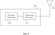
- methods 300 and 400 may be implemented on a network device (e.g., eNB, gNB, base station, and so on).
- a network device e.g., eNB, gNB, base station, and so on.
- FIG. 3 shows a flowchart of a method 300 for RI identification and mitigation according to the invention.
- the method 300 includes, at step 310, determining that an interference type is a remote interference.
- the method 300 may further include measuring an interference level, and determining that it is greater than or equal to a first threshold.
- the interference level may be an uplink interference level.
- determining the interference type includes measuring an interference level in a frequency band corresponding to a communication, and determining that the interference level in the frequency band is higher than that in one or more other frequency bands.
- the method 300 includes, at step 320, transmitting, in response to the determining, a reference signal indicative of a resource that was affected by the remote interference.
- the reference signal is a remote interference management-reference signal (RIM-RS).
- the resource is an uplink resource.
- the reference signal is transmitted on one or more last downlink symbols that are positioned before flexible symbols or guard period symbols.
- multiple reference signals are transmitted on downlink symbols that are positioned before flexible symbols or guard period symbols.
- the method 300 further includes performing a remote interference management (RIM) procedure.
- performing the RIM procedure includes pausing a communication on the resource for a period of time.
- performing the RIM procedure includes increasing a transmit power or adjusting a modulation and coding scheme (MCS) for a subsequent communication on the resource.
- performing the RIM procedure includes reconfiguring symbols of the resource that was affected by the remote interference to flexible symbols or guard period symbols.
- MCS modulation and coding scheme
- the method 400 includes, at step 420, determining a resource that was affected by a remote interference based on a position of the reference signal in the frame.
- the resource is an uplink resource and the frame is an uplink frame.
- the detecting includes detecting the reference signal on downlink symbols of the frame. Furthermore, the determining includes determining that the resource comprises uplink symbols of the frame that are positioned before the downlink symbols of the frame.
Landscapes
- Engineering & Computer Science (AREA)
- Computer Networks & Wireless Communication (AREA)
- Signal Processing (AREA)
- Power Engineering (AREA)
- Quality & Reliability (AREA)
- Physics & Mathematics (AREA)
- Electromagnetism (AREA)
- Mobile Radio Communication Systems (AREA)
Claims (9)
- Procédé de communication sans fil, mis en œuvre par une station de base, comprenant :la détermination (310) qu'un type d'interférence est une interférence à distance ; etla transmission (320), en réponse à la détermination, d'un signal de référence indicatif d'une ressource qui a été affectée par l'interférence à distance,caractérisé en ce que la détermination comprend :la détermination du fait de savoir si un commutateur indiquant que le type d'interférence est l'interférence à distance est activé ;la mesure d'un niveau d'interférence ; etla détermination du fait que le niveau d'interférence est supérieur ou égal à un premier seuil, et la détermination que le type d'interférence est l'interférence à distance étant effectuée sur la base de la détermination que le niveau d'interférence est supérieur ou égal au premier seuil dans le cas où le commutateur est déterminé comme étant activé et de la détermination que le type d'interférence est l'interférence à distance est effectuée lorsque des conditions supplémentaires sont satisfaites en plus de la détermination que le niveau d'interférence est supérieur ou égal au premier seuil dans le cas où le commutateur est déterminé comme étant désactivé,dans lequel les conditions supplémentaires comprennent une première condition basée sur le fait que le niveau d'interférence diminue ou non pendant une durée, une deuxième condition basée sur le fait que le niveau d'interférence dans une bande de fréquences est supérieur ou non à celui dans une ou plusieurs autres bandes de fréquences, et une troisième condition basée sur un signal reçu d'au moins un dispositif de réseau.
- Procédé selon la revendication 1, dans lequel la mesure est effectuée pendant la durée d'une trame, et dans lequel la première condition supplémentaire est satisfaite lorsque le niveau d'interférence diminue pendant la durée.
- Procédé selon la revendication 1, dans lequel la mesure est effectuée dans la bande de fréquences correspondant à une communication, et dans lequel la deuxième condition supplémentaire est satisfaite lorsque le niveau d'interférence dans la bande de fréquences est supérieur à celui dans la ou les autres bandes de fréquences.
- Procédé selon la revendication 1, dans lequel la troisième condition supplémentaire est satisfaite lorsque :
le signal indique que l'interférence subie par l'au moins un dispositif de réseau est l'interférence à distance. - Procédé selon la revendication 1, dans lequel la mesure du niveau d'interférence est effectuée sur des ressources de mesure, et le procédé comprenant en outre :
la transmission, avant la mesure du niveau d'interférence, d'informations associées aux ressources de mesure à des cellules voisines par le biais d'une signalisation de liaison ou d'une signalisation aérienne, les cellules voisines ne communiquant pas sur les ressources de mesure pendant la mesure du niveau d'interférence. - Procédé selon l'une quelconque des revendications 1 à 5, dans lequel le signal de référence est transmis sur un ou plusieurs derniers symboles de liaison descendante qui sont positionnés avant des symboles flexibles ou des symboles de période de garde.
- Procédé selon la revendication 1, comprenant en outre :
l'exécution d'une procédure de gestion d'interférence à distance, RIM, la procédure RIM comprenant :la reconfiguration de symboles de la ressource qui a été affectée par l'interférence à distance en symboles flexibles ou en symboles de période de garde, oula mise en pause d'une communication sur la ressource pendant une période de temps, ou l'augmentation d'une puissance d'émission ou l'ajustement d'un schéma de modulation et de codage, MCS, pour une communication ultérieure sur la ressource. - Procédé selon la revendication 1, dans lequel l'émission comprend :1) l'émission de multiples signaux de référence sur des symboles de liaison descendante qui sont positionnés avant des symboles flexibles ou des symboles de période de garde, ou2) la génération d'une séquence de référence en brouillant une séquence de données avec des informations correspondant à la ressource qui a été affectée par l'interférence à distance et la génération du signal de référence sur la base de la séquence de référence.
- Station de base comprenant un processeur et une mémoire, dans laquelle le processeur est configuré pour lire un code à partir de la mémoire et mettre en œuvre un procédé décrit dans l'une quelconque des revendications 1 à 8.
Applications Claiming Priority (1)
| Application Number | Priority Date | Filing Date | Title |
|---|---|---|---|
| PCT/CN2018/101531 WO2020034239A1 (fr) | 2018-08-21 | 2018-08-21 | Identification et atténuation de brouillage à distance |
Publications (3)
| Publication Number | Publication Date |
|---|---|
| EP3841777A1 EP3841777A1 (fr) | 2021-06-30 |
| EP3841777A4 EP3841777A4 (fr) | 2022-05-04 |
| EP3841777B1 true EP3841777B1 (fr) | 2025-07-02 |
Family
ID=69524616
Family Applications (1)
| Application Number | Title | Priority Date | Filing Date |
|---|---|---|---|
| EP18930083.3A Active EP3841777B1 (fr) | 2018-08-21 | 2018-08-21 | Identification et atténuation de brouillage à distance |
Country Status (4)
| Country | Link |
|---|---|
| US (1) | US11894953B2 (fr) |
| EP (1) | EP3841777B1 (fr) |
| CN (1) | CN112586025B (fr) |
| WO (1) | WO2020034239A1 (fr) |
Families Citing this family (5)
| Publication number | Priority date | Publication date | Assignee | Title |
|---|---|---|---|---|
| US12120048B2 (en) * | 2018-09-28 | 2024-10-15 | Apple Inc. | Remote interference management reference signal |
| EP4342206A4 (fr) | 2021-09-15 | 2024-10-09 | Samsung Electronics Co., Ltd. | Procédé et dispositif électronique pour identifier des noeuds agresseurs dans un réseau de communication |
| CN115835382B (zh) * | 2023-02-16 | 2023-07-04 | 中国移动通信有限公司研究院 | 干扰抑制方法、装置、设备及可读存储介质 |
| US12526122B2 (en) * | 2023-02-17 | 2026-01-13 | Verizon Patent And Licensing Inc. | Flexible configuration of indoor radios to facilitate coexistence with outdoor radios |
| WO2024250139A1 (fr) * | 2023-06-05 | 2024-12-12 | Telefonaktiebolaget Lm Ericsson (Publ) | Brouillage dans un système fonctionnant en tdd |
Family Cites Families (10)
| Publication number | Priority date | Publication date | Assignee | Title |
|---|---|---|---|---|
| MX2009010279A (es) * | 2007-03-30 | 2009-10-13 | Ntt Docomo Inc | Sistema movil de comunicaciones, aparato de estacion base, aparato de usuario y metodo. |
| US8666398B2 (en) * | 2010-04-13 | 2014-03-04 | Qualcomm Incorporated | Random access procedure enhancements for heterogeneous networks |
| EP2678947A4 (fr) * | 2011-02-24 | 2016-12-28 | ERICSSON TELEFON AB L M (publ) | Réduction d'interférence provoquée par un conduit atmosphérique dans un système de communications mobiles |
| JP5690019B2 (ja) * | 2011-04-08 | 2015-03-25 | テレフオンアクチーボラゲット エル エム エリクソン(パブル) | 無線通信システムにおいて大気ダクトによって生じる干渉の低減 |
| CN106464345B (zh) * | 2014-06-05 | 2019-03-12 | 英特尔Ip公司 | 用于全双工无线通信的干扰管理技术 |
| US10349307B2 (en) * | 2014-08-13 | 2019-07-09 | Lg Electronics Inc. | Method and terminal for removing interference |
| CN106488488A (zh) * | 2015-08-31 | 2017-03-08 | 中兴通讯股份有限公司 | 一种基站干扰检测方法和装置 |
| CN107801199B (zh) * | 2016-09-07 | 2022-04-29 | 中兴通讯股份有限公司 | 一种定位干扰源小区的方法、装置和系统 |
| CN107888318A (zh) * | 2016-09-30 | 2018-04-06 | 中国移动通信有限公司研究院 | 干扰分析方法及装置 |
| US11005586B2 (en) * | 2018-07-31 | 2021-05-11 | Qualcomm Incorporated | Reference signal monitoring mechanism for remote interference management |
-
2018
- 2018-08-21 EP EP18930083.3A patent/EP3841777B1/fr active Active
- 2018-08-21 CN CN201880096766.0A patent/CN112586025B/zh active Active
- 2018-08-21 WO PCT/CN2018/101531 patent/WO2020034239A1/fr not_active Ceased
-
2021
- 2021-02-19 US US17/180,133 patent/US11894953B2/en active Active
Also Published As
| Publication number | Publication date |
|---|---|
| EP3841777A1 (fr) | 2021-06-30 |
| EP3841777A4 (fr) | 2022-05-04 |
| CN112586025A (zh) | 2021-03-30 |
| WO2020034239A1 (fr) | 2020-02-20 |
| US11894953B2 (en) | 2024-02-06 |
| CN112586025B (zh) | 2023-05-16 |
| US20210234731A1 (en) | 2021-07-29 |
Similar Documents
| Publication | Publication Date | Title |
|---|---|---|
| US11894953B2 (en) | Remote interference identification and mitigation | |
| EP3399807B1 (fr) | Procédé et dispositif dans un réseau de communication | |
| US9820244B2 (en) | Time-advanced random access channel transmission | |
| US11930520B2 (en) | Interference management in wireless systems | |
| CN102812756B (zh) | 基站设备、终端设备、接收器端基站设备以及无线通信方法 | |
| US20120282889A1 (en) | Base station device | |
| US20140112254A1 (en) | Methods and nodes for random access | |
| KR101257150B1 (ko) | 통신 네트워크에서의 방법 및 그 장치 | |
| CN110300442B (zh) | 一种信号发送方法及网络设备 | |
| CN101785220A (zh) | 终端装置、基站装置、以及频率资源分配方法 | |
| US11109330B2 (en) | Method for determining correction time in wireless communication system and apparatus therefor | |
| CN110036659B (zh) | 用于无线通信系统中间歇干扰条件下的链路自适应的方法和设备 | |
| TWI435577B (zh) | 在通訊系統中傳送測距前置碼至基地台的使用者終端及方法 | |
| GB2559382A (en) | Systems and methods for cell range extension | |
| US9750032B2 (en) | Base station device, wireless communication system, and base station device control method | |
| US20140364065A1 (en) | Method for joint cell measurement and system information identification | |
| CN110958613A (zh) | 大气波导干扰处理方法、装置、基站以及通信系统 | |
| KR102301820B1 (ko) | 무선 통신 시스템의 보정 시간 결정 방법 및 이를 위한 장치 | |
| CN102790636B (zh) | 一种智能天线校准序列的发送方法 | |
| JP6194715B2 (ja) | 基地局装置および通信システム | |
| WO2014179351A1 (fr) | Procédé et système de coordination de brouillage dans un système lte-tdd sans fil | |
| EP2627051A1 (fr) | Evitement de collision de symbole de référence dans un réseau radio cellulaire | |
| CN111130730A (zh) | 信号发送方法、信息传输方法、干扰抑制方法及通信设备 | |
| KR20160094864A (ko) | 비면허 주파수 대역의 무선 통신 시스템에서의 시간 동기 방법 및 그 장치 |
Legal Events
| Date | Code | Title | Description |
|---|---|---|---|
| STAA | Information on the status of an ep patent application or granted ep patent |
Free format text: STATUS: THE INTERNATIONAL PUBLICATION HAS BEEN MADE |
|
| PUAI | Public reference made under article 153(3) epc to a published international application that has entered the european phase |
Free format text: ORIGINAL CODE: 0009012 |
|
| STAA | Information on the status of an ep patent application or granted ep patent |
Free format text: STATUS: REQUEST FOR EXAMINATION WAS MADE |
|
| 17P | Request for examination filed |
Effective date: 20210322 |
|
| AK | Designated contracting states |
Kind code of ref document: A1 Designated state(s): AL AT BE BG CH CY CZ DE DK EE ES FI FR GB GR HR HU IE IS IT LI LT LU LV MC MK MT NL NO PL PT RO RS SE SI SK SM TR |
|
| DAV | Request for validation of the european patent (deleted) | ||
| DAX | Request for extension of the european patent (deleted) | ||
| A4 | Supplementary search report drawn up and despatched |
Effective date: 20220404 |
|
| RIC1 | Information provided on ipc code assigned before grant |
Ipc: H04J 11/00 20060101ALN20220328BHEP Ipc: H04W 92/20 20090101ALN20220328BHEP Ipc: H04W 72/08 20090101ALN20220328BHEP Ipc: H04W 24/08 20090101ALI20220328BHEP Ipc: H04W 24/02 20090101AFI20220328BHEP |
|
| STAA | Information on the status of an ep patent application or granted ep patent |
Free format text: STATUS: EXAMINATION IS IN PROGRESS |
|
| 17Q | First examination report despatched |
Effective date: 20231019 |
|
| GRAP | Despatch of communication of intention to grant a patent |
Free format text: ORIGINAL CODE: EPIDOSNIGR1 |
|
| STAA | Information on the status of an ep patent application or granted ep patent |
Free format text: STATUS: GRANT OF PATENT IS INTENDED |
|
| RIC1 | Information provided on ipc code assigned before grant |
Ipc: H04J 11/00 20060101ALN20250319BHEP Ipc: H04W 92/20 20090101ALN20250319BHEP Ipc: H04W 72/541 20230101ALN20250319BHEP Ipc: H04W 24/08 20090101ALI20250319BHEP Ipc: H04W 24/02 20090101AFI20250319BHEP |
|
| INTG | Intention to grant announced |
Effective date: 20250403 |
|
| GRAS | Grant fee paid |
Free format text: ORIGINAL CODE: EPIDOSNIGR3 |
|
| GRAA | (expected) grant |
Free format text: ORIGINAL CODE: 0009210 |
|
| STAA | Information on the status of an ep patent application or granted ep patent |
Free format text: STATUS: THE PATENT HAS BEEN GRANTED |
|
| AK | Designated contracting states |
Kind code of ref document: B1 Designated state(s): AL AT BE BG CH CY CZ DE DK EE ES FI FR GB GR HR HU IE IS IT LI LT LU LV MC MK MT NL NO PL PT RO RS SE SI SK SM TR |
|
| REG | Reference to a national code |
Ref country code: GB Ref legal event code: FG4D |
|
| REG | Reference to a national code |
Ref country code: CH Ref legal event code: EP |
|
| REG | Reference to a national code |
Ref country code: DE Ref legal event code: R096 Ref document number: 602018083326 Country of ref document: DE |
|
| REG | Reference to a national code |
Ref country code: IE Ref legal event code: FG4D |
|
| PGFP | Annual fee paid to national office [announced via postgrant information from national office to epo] |
Ref country code: DE Payment date: 20250708 Year of fee payment: 8 |
|
| PGFP | Annual fee paid to national office [announced via postgrant information from national office to epo] |
Ref country code: GB Payment date: 20250710 Year of fee payment: 8 |
|
| PGFP | Annual fee paid to national office [announced via postgrant information from national office to epo] |
Ref country code: FR Payment date: 20250708 Year of fee payment: 8 |
|
| REG | Reference to a national code |
Ref country code: NL Ref legal event code: MP Effective date: 20250702 |
|
| PG25 | Lapsed in a contracting state [announced via postgrant information from national office to epo] |
Ref country code: PT Free format text: LAPSE BECAUSE OF FAILURE TO SUBMIT A TRANSLATION OF THE DESCRIPTION OR TO PAY THE FEE WITHIN THE PRESCRIBED TIME-LIMIT Effective date: 20251103 |
|
| PG25 | Lapsed in a contracting state [announced via postgrant information from national office to epo] |
Ref country code: NL Free format text: LAPSE BECAUSE OF FAILURE TO SUBMIT A TRANSLATION OF THE DESCRIPTION OR TO PAY THE FEE WITHIN THE PRESCRIBED TIME-LIMIT Effective date: 20250702 |
|
| REG | Reference to a national code |
Ref country code: AT Ref legal event code: MK05 Ref document number: 1810713 Country of ref document: AT Kind code of ref document: T Effective date: 20250702 |
|
| PG25 | Lapsed in a contracting state [announced via postgrant information from national office to epo] |
Ref country code: IS Free format text: LAPSE BECAUSE OF FAILURE TO SUBMIT A TRANSLATION OF THE DESCRIPTION OR TO PAY THE FEE WITHIN THE PRESCRIBED TIME-LIMIT Effective date: 20251102 |
|
| PG25 | Lapsed in a contracting state [announced via postgrant information from national office to epo] |
Ref country code: NO Free format text: LAPSE BECAUSE OF FAILURE TO SUBMIT A TRANSLATION OF THE DESCRIPTION OR TO PAY THE FEE WITHIN THE PRESCRIBED TIME-LIMIT Effective date: 20251002 |
|
| REG | Reference to a national code |
Ref country code: LT Ref legal event code: MG9D |
|
| PG25 | Lapsed in a contracting state [announced via postgrant information from national office to epo] |
Ref country code: AT Free format text: LAPSE BECAUSE OF FAILURE TO SUBMIT A TRANSLATION OF THE DESCRIPTION OR TO PAY THE FEE WITHIN THE PRESCRIBED TIME-LIMIT Effective date: 20250702 |
|
| PG25 | Lapsed in a contracting state [announced via postgrant information from national office to epo] |
Ref country code: FI Free format text: LAPSE BECAUSE OF FAILURE TO SUBMIT A TRANSLATION OF THE DESCRIPTION OR TO PAY THE FEE WITHIN THE PRESCRIBED TIME-LIMIT Effective date: 20250702 |
|
| PG25 | Lapsed in a contracting state [announced via postgrant information from national office to epo] |
Ref country code: HR Free format text: LAPSE BECAUSE OF FAILURE TO SUBMIT A TRANSLATION OF THE DESCRIPTION OR TO PAY THE FEE WITHIN THE PRESCRIBED TIME-LIMIT Effective date: 20250702 |
|
| PG25 | Lapsed in a contracting state [announced via postgrant information from national office to epo] |
Ref country code: GR Free format text: LAPSE BECAUSE OF FAILURE TO SUBMIT A TRANSLATION OF THE DESCRIPTION OR TO PAY THE FEE WITHIN THE PRESCRIBED TIME-LIMIT Effective date: 20251003 |
|
| PG25 | Lapsed in a contracting state [announced via postgrant information from national office to epo] |
Ref country code: SE Free format text: LAPSE BECAUSE OF FAILURE TO SUBMIT A TRANSLATION OF THE DESCRIPTION OR TO PAY THE FEE WITHIN THE PRESCRIBED TIME-LIMIT Effective date: 20250702 Ref country code: CZ Free format text: LAPSE BECAUSE OF FAILURE TO SUBMIT A TRANSLATION OF THE DESCRIPTION OR TO PAY THE FEE WITHIN THE PRESCRIBED TIME-LIMIT Effective date: 20250702 |
|
| PG25 | Lapsed in a contracting state [announced via postgrant information from national office to epo] |
Ref country code: LV Free format text: LAPSE BECAUSE OF FAILURE TO SUBMIT A TRANSLATION OF THE DESCRIPTION OR TO PAY THE FEE WITHIN THE PRESCRIBED TIME-LIMIT Effective date: 20250702 |
|
| PG25 | Lapsed in a contracting state [announced via postgrant information from national office to epo] |
Ref country code: PL Free format text: LAPSE BECAUSE OF FAILURE TO SUBMIT A TRANSLATION OF THE DESCRIPTION OR TO PAY THE FEE WITHIN THE PRESCRIBED TIME-LIMIT Effective date: 20250702 Ref country code: BG Free format text: LAPSE BECAUSE OF FAILURE TO SUBMIT A TRANSLATION OF THE DESCRIPTION OR TO PAY THE FEE WITHIN THE PRESCRIBED TIME-LIMIT Effective date: 20250702 |
|
| PG25 | Lapsed in a contracting state [announced via postgrant information from national office to epo] |
Ref country code: RS Free format text: LAPSE BECAUSE OF FAILURE TO SUBMIT A TRANSLATION OF THE DESCRIPTION OR TO PAY THE FEE WITHIN THE PRESCRIBED TIME-LIMIT Effective date: 20251002 |
|
| PG25 | Lapsed in a contracting state [announced via postgrant information from national office to epo] |
Ref country code: ES Free format text: LAPSE BECAUSE OF FAILURE TO SUBMIT A TRANSLATION OF THE DESCRIPTION OR TO PAY THE FEE WITHIN THE PRESCRIBED TIME-LIMIT Effective date: 20250702 |
|
| PG25 | Lapsed in a contracting state [announced via postgrant information from national office to epo] |
Ref country code: RO Free format text: LAPSE BECAUSE OF FAILURE TO SUBMIT A TRANSLATION OF THE DESCRIPTION OR TO PAY THE FEE WITHIN THE PRESCRIBED TIME-LIMIT Effective date: 20250702 |
|
| REG | Reference to a national code |
Ref country code: CH Ref legal event code: H13 Free format text: ST27 STATUS EVENT CODE: U-0-0-H10-H13 (AS PROVIDED BY THE NATIONAL OFFICE) Effective date: 20260324 |
|
| PG25 | Lapsed in a contracting state [announced via postgrant information from national office to epo] |
Ref country code: SM Free format text: LAPSE BECAUSE OF FAILURE TO SUBMIT A TRANSLATION OF THE DESCRIPTION OR TO PAY THE FEE WITHIN THE PRESCRIBED TIME-LIMIT Effective date: 20250702 |
|
| PG25 | Lapsed in a contracting state [announced via postgrant information from national office to epo] |
Ref country code: DK Free format text: LAPSE BECAUSE OF FAILURE TO SUBMIT A TRANSLATION OF THE DESCRIPTION OR TO PAY THE FEE WITHIN THE PRESCRIBED TIME-LIMIT Effective date: 20250702 |
|
| PG25 | Lapsed in a contracting state [announced via postgrant information from national office to epo] |
Ref country code: LU Free format text: LAPSE BECAUSE OF NON-PAYMENT OF DUE FEES Effective date: 20250821 Ref country code: IT Free format text: LAPSE BECAUSE OF FAILURE TO SUBMIT A TRANSLATION OF THE DESCRIPTION OR TO PAY THE FEE WITHIN THE PRESCRIBED TIME-LIMIT Effective date: 20250702 |
|
| PG25 | Lapsed in a contracting state [announced via postgrant information from national office to epo] |
Ref country code: CH Free format text: LAPSE BECAUSE OF NON-PAYMENT OF DUE FEES Effective date: 20250831 |
|
| PG25 | Lapsed in a contracting state [announced via postgrant information from national office to epo] |
Ref country code: SK Free format text: LAPSE BECAUSE OF FAILURE TO SUBMIT A TRANSLATION OF THE DESCRIPTION OR TO PAY THE FEE WITHIN THE PRESCRIBED TIME-LIMIT Effective date: 20250702 Ref country code: EE Free format text: LAPSE BECAUSE OF FAILURE TO SUBMIT A TRANSLATION OF THE DESCRIPTION OR TO PAY THE FEE WITHIN THE PRESCRIBED TIME-LIMIT Effective date: 20250702 |